Table of Contents
Advertisement
Show/Hide Bookmarks
EDS4900U-REG
00408862
Manual
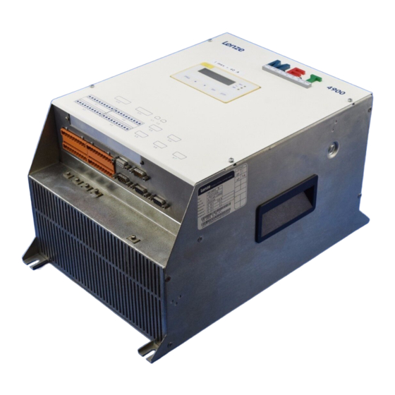
DC speed controller 4800/4900
Table of contents
Preface and general
information
Safety information
Technical data
Installation
Commissioning
During operation
Configuration
Code table
Troubleshooting and
fault elimination
Maintenance
DC bus connection
Application of brake units
Automation
Accessories and motors
Selection aid
Application examples
Signal-flow charts
Glossary
Table of keywords
Advertisement
Table of Contents

Subscribe to Our Youtube Channel
Related Manuals for Lenze 4800


Summary of Contents for Lenze 4800
- Page 1 EDS4900U-REG Installation 00408862 Commissioning Manual During operation Configuration Code table Troubleshooting and fault elimination Maintenance DC bus connection Application of brake units Automation Accessories and motors Selection aid Application examples Signal-flow charts Glossary Table of keywords DC speed controller 4800/4900...
- Page 2 Lenze endeavours to regularly update all documentation to the current technical state. If you should find any deviations, please refer to the Operating Instructions, which are part of the delivery package, or to your nearest Lenze representative.
-
Page 3: Table Of Contents
Show/Hide Bookmarks Contents Part A Preface and general information ......About these Operating Instructions .. - Page 4 Show/Hide Bookmarks Contents Connection ..........4.3.1 Power connection of standard controller .
- Page 5 Show/Hide Bookmarks Contents Part D Configuration ......... . . Speed-controlled operation .
- Page 6 Show/Hide Bookmarks Contents 7.5.5 Absolute value generator ......7-71 7.5.6 Limitation elements .
- Page 7 Show/Hide Bookmarks Contents Part E Troubleshooting and fault elimination ..... Troubleshooting ..........8.1.1 Display on the operating unit of the controller .
- Page 8 ..13-8 13.3 Pre-assembled Lenze system cable ......13-10 13.3.1...
- Page 9 ........... 18-1 This chapter is part of the Lenze documentation structure. It remains free for the 48XX/49XX DC speed controller.
- Page 10 Show/Hide Bookmarks Contents viii 48XX/49XXSHB00399...
-
Page 11: Preface And General Information
Show/Hide Bookmarks EDS4900U--A 00408849 Manual Part A Contents Preface and general information Safety information DC speed controller 4800/4900... - Page 12 The features, data and versions indicated in this Manual met the state of the art at the time of printing. (Printing date: inner cover pages of the parts). In the event of deviations, please see the Operating Instructions or contact Lenze. revised Edition of:...
-
Page 13: Preface And General Information
- 1 Accessory kit with plug-in terminals - After receipt of the delivery, check immediately whether the scope of delivery matches the accompanying papers. Lenze does not accept any liability for deficiencies claimed subsequently. Make a claim for - visible transport damage immediately to the forwarder. -
Page 14: 48Xx/49Xx Controller
Show/Hide Bookmarks Preface and general information 48XX/49XX controller 1.3.1 Labelling - Lenze 48XX/49XX controllers are unambiguously designated by the contents of the nameplate. - CE mark: - Conformity with the Low-Voltage Directive - Conformity with the EMC Directive - Manufacturer - Lenze GmbH &... -
Page 15: Legal Regulations
- improper working on and with the controller Warranty - Terms of warranty: see terms of sale and delivery of Lenze GmbH & Co KG. - Warranty claims must be made immediately after detecting defects or faults. - The warranty is void in all cases where liability claims cannot be made. -
Page 16: Ec Directives/Declaration Of Conformity
For the installation of CE-typical drive systems with the basic version of 48XX/49XX controllers and the variants V011, V013 and V014, Lenze has already proved the conformity with the EMC Directive (see chapter 4.4). - Page 17 CE Mark Directive (93/68/EEC) 48XX/49XX controllers were developed, designed, and manufactured in compliance with the EC Directive under the sole responsibility of Lenze GmbH & Co KG, Postfach 10 13 52, D-31763 Hameln Considered standards: Standard DIN EN 50178...
-
Page 18: Ec Directive Electromagnetic Compatibility
EC EMC Directive and the compliance with the ”Law about the Electromagnetic Compatibility of Devices”. - Lenze has verified the conformity of 48XX/49XX controllers integrated into certain defined drive systems . In the following, these systems are called ”CE-typical drive systems” (see chapter 4.4). - Page 19 Amendment of 08 August, 1995). The EMC can only be verified when the controller is integrated into a drive system. Lenze GmbH & Co KG, Postfach 10 13 52, D-31763 Hameln declares that the described ”CE-typical drive systems” with the basic version of 48XX/49XX controller and the variants V011, V013 and V014 comply with the above EC Directive.
- Page 20 Show/Hide Bookmarks Preface and general information Generic standards considered for the test of noise emission: Basic standard Test Limit value EN 61000-4-2 3/95 Electrostatic discharge on housing and heatsink Severity 3 6kV for contact, 8kV clearance IEC 1000-4-3 2/95 Electromagnetic fields Severity 3 Frequency range 26-1000MHz 10V/m...
-
Page 21: Ec Machinery Directive
48XX/49XX controllers were developed, designed, and manufactured under the sole responsibility of Lenze GmbH & Co KG, Postfach 10 13 52, D-31763 Hameln Commissioning of the controllers is prohibited until it is proven that the machine in which they are to be installed corresponds to the EC Machinery Directive. - Page 22 Show/Hide Bookmarks Preface and general information 1-10 48XX/49XXSHB0399...
-
Page 23: Safety Information
Show/Hide Bookmarks Safety information Safety information Safety and application notes for controllers (to: Low-Voltage Directive 73/23/EEC) 1. General 4. Erection During operation, drive controllers may have, according to their The devices must be erected and cooled according to the type of protection, live, bare, in some cases also movable or regulations of the corresponding documentation. -
Page 24: Persons Responsible For The Safety
Show/Hide Bookmarks Safety information Persons responsible for the safety Operator ( An operator is any natural or legal person who uses the drive system or on behalf of whom the drive system is used. ( The operator or his safety officer are obliged to ensure that - all relevant regulations, notes and laws are observed - only qualified personnel work on and with the drive system. -
Page 25: General Safety Information
- measures covering the complete system ( The drive system must only be operated in perfect condition. ( Retrofittings, modifications, or changes are generally prohibited. For some applications, Lenze authorizes the operation of retrofitted, modified or changed controllers. Please contact Lenze. Residual hazards Excessive speed Drive systems may reach dangerously high speeds (e.g. -
Page 26: Layout Of The Safety Information
Show/Hide Bookmarks Safety information Layout of the safety information ( All safety information given in these Operating Instructions has the same layout: Signal word Note - The icon characterizes the type of danger. - The signal word characterizes the severity of danger. - The note describes the danger and suggests how to avoid the danger. -
Page 27: Part B
Show/Hide Bookmarks EDS4900U--B 00408850 Manual Part B Technical Data Installation DC speed controller 4800/4900... -
Page 28: Manual
The features, data and versions indicated in this Manual met the state of the art at the time of printing. (Printing date: inner cover pages of the parts). In the event of deviations, please see the Operating Instructions or contact Lenze. revised Edition of:... -
Page 29: Technical Data
Show/Hide Bookmarks Technical Data Technical data Features Controller and system features ( Control electronics and system software are the same for 48XX/49XX ( Digital speed feedback with resolver or incremental encoder ( Torque control with superimposed speed monitoring for winding drives ( Phase control for drift-free positioning ( Digital frequency coupling as setpoint bar or setpoint cascade for - phase synchronisation... - Page 30 Show/Hide Bookmarks Technical Data Speed feedback systems ( Resolver feedback with encoder emulation for superimposed systems (synchronizing systems, positioning controls, etc.) ( Incremental encoder feedback ( DC tacho feedback ( Armature voltage feedback Inputs ( Digital - 8 isolated inputs (24 V level), 5 of them freely assignable - 1 serial interface RS 485 or RS 232 (1200 ...
-
Page 31: General Data / Application Conditions
Show/Hide Bookmarks Technical Data General data / application conditions Field Values Type of protection IP20 to DIN 40050, steel sheet housing Permissible humidity Relative humidity 90%, no condensation Temperature ranges -25 •C...+ 55 •C Storage -25 •C...+ 70 •C Transport h $ 1000m : 100% rated armature current Influence of the installation height h $ 2000m : 95% rated armature current... -
Page 32: Rated Data
Show/Hide Bookmarks Technical Data Rated data 3.3.1 Mains voltage 400V ( Controllers 4902 to 4907 (4Q controllers) Type 4902 4903 4904 4905 4906 4907 Order No. EVD 4902-E EVD 4903-E EVD 4904-E EVD 4905-E EVD 4906-E EVD 4907-E Output power [kW] 10.5 23.1... - Page 33 Show/Hide Bookmarks Technical Data ( Controllers 4808 to 4813 (2Q controllers) Type 4808 4809 4811 4812 4813 Order No. EVD 4808-E EVD 4809-E EVD 4811-E EVD 4812-E EVD 4813 Output power [kW] 3 ô 340...460 V~ á0%, 50...60Hz Mains voltage mains = 400 V (1.15 ¼...
-
Page 34: Mains Voltage 500V (Variant V014)
Show/Hide Bookmarks Technical Data 3.3.2 Mains voltage 500V (Variant V014) ( Controllers 4903 to 4907 (4Q controllers) Type 4903 4904 4905 4906 4907 Order No. 4903-E-V014 4904-E-V014 4905-E-V014 4906-E-V014 4907-E-V014 Output power [kW] 13.1 28.8 57.7 3ô410...550 V~ –0%, 50...60 Hz Mains voltage mains = 500V (1.05 ¼... - Page 35 Show/Hide Bookmarks Technical Data ( Controllers 4808 to 4813 (4Q controllers) Type 4808 4809 4811 4812 4813 Order No. 4808-E-V014 4809-E-V014 4811-E-V014 4812-E-V014 4813-E-V014 Output power [kW] 3ô 410...550 V~ á0%, 50...60Hz Mains voltage mains = 500 V (1.15 ¼ V Armature voltage 575 V if V mains...
-
Page 36: Dimensions
Show/Hide Bookmarks Technical Data Dimensions 3.4.1 Controller 4902 to 4X09 4900 ”A” ”A” V1 V2 4900Str001 FIG 4-1 Dimensions of the controllers 4902 to 4907, 4X08 and 4X09 all dimensions in mm Type 4902 / 4903 / 4904 4905 / 4906 / 4907 4808 / 4809 / 4908 / 4909 322 48XX/49XXSHB0399... -
Page 37: Controllers 4811 To 4813, 4911 To 4913
Show/Hide Bookmarks Technical Data 3.4.2 Controllers 4811 to 4813, 4911 to 4913 4900 4900Str002 FIG 4-2 Dimensions of the controllers 4X11 to 4X13 all dimensions in mm Type 4811 - 4813 / 4911 - 4913 322 48XX/49XXSHB0399... - Page 38 Show/Hide Bookmarks Technical Data 3-10 48XX/49XXSHB0399...
-
Page 39: Installation
Show/Hide Bookmarks Installation Installation Mechanical installation 4.1.1 Important notes ( Ensure free installation space above and below the controller: - 100 mm for 4902...4907 - 150 mm for 4X08...4X13 ( Ensure unimpeded ventilation of cooling air and outlet of exhaust air. ( If the cooling air contains pollutants (dust, fluff, grease, aggressive gases), which may impair the function of the controller: - Take suitable preventive measures , e.g. -
Page 40: Electrical Installation
Show/Hide Bookmarks Installation Electrical installation For information on the installation according to EMC, see chapter 4.4 4.2.1 Protection of persons ( Protection of persons and animals according to DIN VDE 0100 with current-operated protective devices: The inverters are equipped with a mains rectifier. After a short-circuit to frame, a DC fault current may prevent the tripping of the current-operated protective device. -
Page 41: Protection Of The Controller
Show/Hide Bookmarks Installation 4.2.2 Protection of the controller Stop! The controllers contain electrostatically sensitive components: Prior to assembly and service operations, the personnel must be free of electrostatic charge, e.g. by touching the PE fixing screw or other grounded metal surfaces in the control cabinet. -
Page 42: Earthing Of The Control Electronics
With grounded phase Operation is impossible. With isolated neutral (IT mains) Operation with the recommended RFI filter Contact Lenze. The RFI filter will be is only possible if an isolating transformer destroyed when directly connected is preconnected. The neutral of the to the IT mains and fault “earth... -
Page 43: Connection
Show/Hide Bookmarks Installation Connection Connection between controller and motor Lenze controller Motor (to DIN 42017/VDE 0530 part 8) Function Terminal Terminal Others Motor type Armature voltage DC motor B2, A2 uncompensated with commutating winding Excitation voltage F5, (for higher connection voltages) -
Page 44: Power Connection Of Standard Controller
Show/Hide Bookmarks Installation 4.3.1 Power connection of standard controller 4902/3/5LP 4902VP F1 F2 FF16A M0,5A 500V 500V L1 L2 L3 L1.1 L3.1 L1.2L2.2 L3.2 F’4 L1 L2 L3 S1 S2 L’1 L’2 L’3 F’1...F’3 F’’1...F’’3 = 340 ... 460 V~ 0% 50 ... 60 Hz mains L1 L2 L3 4900Str003... - Page 45 Show/Hide Bookmarks Installation 4900Str128 FIG 4-4 Power connection of controllers 4X08 to 4X09 Mains contactor F’1...F’4 Semiconductor fuses for the protection of controllers F’’1...F’’5 Line protection fuses Commutating choke (mains choke) RFI filter RFI filter for separate fan supply BR3 - BR5 0W wire bridge ¥...
- Page 46 Show/Hide Bookmarks Installation 4900Str129 FIG 4-5 Power connection of controllers 4X11 to 4X13 Mains contactor F1.1 ... F3.2 Semiconductor fuses for controller protection F’’1...F’’5 Line protection fuses Commutating choke (mains choke) RFI filter RFI filter for separate fan supply BR3 - BR5 0W wire bridge ¥...
-
Page 47: Separate Supply Of The Field-Current Bridge At A High Motor Field Voltage
Show/Hide Bookmarks Installation 4.3.2 Separate supply of the field-current bridge at a high motor field voltage Stop! Ensure correct phase connection of the separate field supply. Incorrect connection leads to blown fuses. The phase shift of the voltages from the power stage to the control electronics must be smaller than 2 °(electrically). - Page 48 Show/Hide Bookmarks Installation 4902/3/5LP 4902VP F1 F2 FF16A M0,5A 500V 500V L1 L2 L3 L1.1 L3.1 L1.2 L2.2 L3.2 L K2 L K2 F’4 F’’4 F’’5 S1 S2 L1 L2 L3 L’1 L’2 L’3 F’1...F’3 F’’1...F’’3 = 340 ... 460 V~ 0% 50 ... 60 Hz mains L1 L2 L3 4900Str006...
-
Page 49: Separate Supply For The Control Electronics
Show/Hide Bookmarks Installation 4.3.3 Separate supply for the control electronics Stop! Ensure correct phase connection of the separate mains supply. Incorrect connection leads to blown fuses. ( The phase shift of the voltages from the power stage to the control electronics must be smaller than 2°(electrically). - Page 50 Show/Hide Bookmarks Installation 4900Str130 FIG 4-7 Power connection for controllers 4902 to 4907 and 4X08 to 4X13 Mains contactor F’1...F’3 Semiconductor fuses for controller protection F’’1...F’’3 Line protection fuses F’’6...F’’8 Cable protection fuses 4A Commutating choke RFI filter Main switch ¥...
-
Page 51: Control Connections
Show/Hide Bookmarks Installation 4.3.4 Control connections 1 2 3 4 5 6 7 8 9 10 20 21 22 28 E1 E2 E3 E4 E5 39 40 41 44 45K11 K14A1 A2 A3 A4 A5 59 60 61 62 63 80VE990 FE 4900Str008 FIG 4-8 Control connections for the controller... -
Page 52: Connection Of Analog Signals
Show/Hide Bookmarks Installation 4.3.4.1 Connection of analog signals S4/5 S3/2 S3/1 8x 3,3nF 61 62 63 R > 1,5 k R > 3 k 4900Str010 FIG 4-10 Analog inputs and outputs External torque limitation Setpoint 2 Actual value signal with tacho feedback Analog Additional setpoint Setpoint 3... - Page 53 Show/Hide Bookmarks Installation Analog inputs Terminal Switch position Level Resolution 1, 2 Setpoint 2 -10V...+ 10V 12 bit + sign with ground reference (factory setting) Setpoint 2 -10V...+ 10V 12 bit + sign differential input 3, 4 Actual value -10V...+ 10V 12 bit + sign 1 2 3 4 Actual value...
- Page 54 Show/Hide Bookmarks Installation Analog outputs (monitor outputs) Terminal Switch position Level Resolution Internal ground, GND Actual current value -5 V...+ 5 V correspond to the rated current of the controller Monitor 1 -10V...10V 11 bit Output voltage(factory setting) Monitor 1 -20mA...+ 20mA 11 bit Output current...
-
Page 55: Connection Of Digital Signals
Show/Hide Bookmarks Installation 4.3.4.2 Connection of digital signals ( All digital inputs and outputs are PLC compatible and separated from the rest of the control module when operated with an external voltage supply (24 V). ( The diagrams show the function assignments according to the factory setting. - Page 56 Show/Hide Bookmarks Installation GND ext. 22 k 10 R 21 22 28 E3 E4 41 44 45 A3 A4 6 7 8 9 10 11 12 1 2 3 4 4900Str011 FIG 4-11 Digital inputs and outputs with external voltage supply (24 V) GND ext.
- Page 57 Show/Hide Bookmarks Installation Digital inputs Name Terminal Level for activation Programming (factory setting) see chapter Voltage supply 15V, 100mA Removal of quick stop, CW rotation HIGH Remove quick stop, CCW rotation HIGH Controller enable - Ctrl. enable HIGH Freely assignable input HIGH (TRIP set) Freely assignable input...
- Page 58 Show/Hide Bookmarks Installation Relay output Terminal (factory setting) K11, K14 Floating relay output, contact load capacitiy: 50V / 0.5A (TRIP) 4900Str063 Additional digital inputs and outputs with 4X08...4X13 The controllers 4X08...4X13 are equipped with additional control terminals to monitor the fuses. The following current flow charts show the factory setting of the internal wiring and give suggestions on how to include an external fuse monitoring.
-
Page 59: Feedback Systems
( 2-pole resolver (V = 10 V, f = 5 kHz) ( Connection to a 9-pole Sub D socket X7 - We recommend to use the pre-cut Lenze system cable (see chapter 13.3). ( Resolver cable and resolver are monitored for wire breakage (fault message ”Sd2”) - Page 60 - Connect both screen ends. - Use cable cross-sections indicated. ( The feedback system can be activated under C005. ( If resolvers are used which are not specified by Lenze are used, contact your Lenze representative. Incremental encoder feedback ( Incremental encoders with two 5 V complementary signals electrically shifted by 90•(TTL encoders) or HTL encoders can be connected.
-
Page 61: Change Of The Direction Of Rotation In 2Q Operation
Show/Hide Bookmarks Installation Pin assignment of socket X5/X9: Signal Pin 8, LC ( ¥) - For encoders without lamp control, assign +5 V...+30V. Otherwise, the controller will indicate fault ”Sd3” or ”Sd4”. Pin 4, VE9 - Is connected to the terminal of the external incremental encoder supply X4/VE9. -
Page 62: Digital Frequency Selection And Encoder Emulation
Show/Hide Bookmarks Installation 4.3.7 Digital frequency selection and encoder emulation Digital frequency input ( Possible digital frequency signals: - Incremental encoder with two 5 V complementary signals electrically shifted by 90•(TTL encoders) or HTL encoder - Encoder emulation of the host (master) ( Connection to a 9-pole Sub D socket X5 or X9, depending on the configuration of C005 - max. - Page 63 Show/Hide Bookmarks Installation Digital frequency output / encoder emulation The output signal of the Sub-D socket X8 can be used for superimposed control circuits to feed back actual values (synchronous running, digital frequency coupling or positioning control). Depending on the configuration under C005, it is assigned as a digital frequency output or as an output for the encoder emulation.
-
Page 64: Serial Interface Rs232/485
(double basic insulation) to VDE 0106, part 1, (protection against electric shock) and to VDE 0160 (reduction of interference) is required for host connection. LECOM-A: with 2 Lenze level converters 2101IB connected to the host or another RS 232C electrical isolation. LECOM-B:... -
Page 65: Fieldbus Connection
- The bridges BR3, BR4, BR5 are not installed! ( Variant V011 with InterBus interface module The interface module type 2110IB connects Lenze controllers with the fast serial communication system InterBus. The module enables the highly dynamic transfer of process data (e. g. setpoints and actual values) and access to all parameters of the controller according to the DRIVECOM profile. - Page 66 Show/Hide Bookmarks Installation ( Variant V013 with PROFIBUS interface module The interface module type 2130IB connects Lenze controllers to the fast serial communication system PROFIBUS. With PROFIBUS it is possible to parameterize and control a controller via a host. 4900Str116...
-
Page 67: Installation Of A Ce-Typical Drive System
Show/Hide Bookmarks Installation Installation of a CE-typical drive system 4.4.1 General notes ( The electromagnetic compatibility of a machine depends on the type of installation and care taken. Please observe: - Assembly - Filters - Screening - Grounding ( For diverging installations, the conformity to the CE EMC Directive requires a check of the machine or system regarding the EMC limit values. -
Page 68: Components Of The Ce-Typical Drive System
Control cables Screened signal cable type LIYCY Encoder cable for digital frequency Lenze system cable or screened signal cable, twisted in pairs, tin plated E-CU braid with 75% optical overlay Encoder cable for resolver Lenze system cable type EWLR or screened signal cable, twisted in pairs, tin plated... - Page 69 Show/Hide Bookmarks Installation Signal cables ( Always screen digital and analog signal cables. - Always connect the signal cables over the shortest possible distance with the screen connections provided at the controller: Connect both screen ends of digital signal cables. ( If potential differences are to be expected, lay an additional compensation cable.
- Page 70 Show/Hide Bookmarks Installation Grounding ( Ensure a good equipotential bonding of all system parts (controller, RFI filter, mains choke, etc.) by cables to a central earthing bus (PE busbar). The prescribed minimum cross-sections must be observed in all cases. ( To comply with the EMC Directive, not the cross-section but the contact surface is decisive.
- Page 71 RFI filter Uncoated, bare metal contact surfaces Commutating choke Armature fuse Metal plug-in casing connected to screen or Lenze system cable Uncoated surface for screen connection PE connection Screened signal cables Screened cables for act. value encoder or setpoint encoder...
- Page 72 Connection fan supply L1/N RFI filter Armature fuses Screened signal cables Metal plug-in casing connected to screen or Lenze system cable Uncoated surface for screen connection Mains choke field supply Line protection fuses for field supply Motor connection with screened cable for act. value encoder...
- Page 73 Connection mains fuse Connection fan supply L1/N RFI filter Uncoated surface for screen connection Metal plug-in casing connected to screen or Lenze system cable Screened signal cables Motor connection with screened cable for act. value encoder Commutating choke Line protection fuses for field supply...
- Page 74 Show/Hide Bookmarks Installation 4-36 48XX/49XXSHB0399...
-
Page 75: Part C
Show/Hide Bookmarks EDS4900U--C 00408852 Manual Part C Commissioning DC speed controller 4800/4900... - Page 76 The features, data and versions indicated in this Manual met the state of the art at the time of printing. (Printing date: inner cover pages of the parts). In the event of deviations, please see the Operating Instructions or contact Lenze. revised Edition of:...
-
Page 77: Commissioning
= 3000 rpm rated = 20V / 1000 rpm tacho ( Simple adaptation to other machine data or special requirements: Use the following for commissioning: - Operating unit of the controller or - LEMOC2 (PC program by LENZE) 48XX/49XXSHB0399... -
Page 78: Wiring Recommendation For Speed Control With Tacho
Show/Hide Bookmarks Commissioning Wiring recommendation for speed control with tacho F’’1...F’’3 F’1...F’3 K2.1 td > tbr. L1 L2 L3 L’1 L’2 L’3 K2.1 L1 L2 L3 4900 21 28 3940 90FE F’4 nset Ctrl. enable nact = 0 4900Str024 FIG 5-1 Flow chart section: Speed control with tacho F’’1...F’’3 Cable protection fuse... - Page 79 Show/Hide Bookmarks Commissioning The following table describes briefly how to commission a DC shunt motor with an attached tacho according to the example in FIG 5-1(see chapter 15). Section Activity see also Switch-on sequence 1.X2/28 (Ctrl. enable) must be opened (LOW) Mains on Controller enable...
-
Page 80: Input Of The Motor Data
Show/Hide Bookmarks Commissioning Input of the motor data Note For internal calculations with field-weakening control, the exact input of the following data is required. See indications on the nameplate of the connected motor. ( C022, C023 Adapt maximum motor current I ( C081 Rated motor power for the power display ( C087 Rated motor speed for the power display ( C083 Rated field current for the field controller... -
Page 81: Controller Enable
Show/Hide Bookmarks Commissioning Controller enable For controller enable, the following conditions must be fulfilled: ( Controller enable via terminal: - Independently of the operating mode, apply a voltage of V = +13...+30 V to X2/28. (Reference potential: X2/39). ( Controller enable via LECOM interface - For the operating modes C001 = -3-, -5-, -6- and -7- (LECOM control), the controller must be additionally enabled via the LECOM interface. -
Page 82: Selection Of Direction Of Rotation And Quick Stop
Show/Hide Bookmarks Commissioning Selection of direction of rotation and quick stop Direction of rotation The polarity of the output voltage V and thus the direction of rotation of the motor depends on the signs of the setpoint, the control of the digital inputs X2/21 and X2/22, and the polarity of the field voltage. - Page 83 (drift-free). The drive can thus generate its maximum torque (independently of the current limit C022, C023). Code Code Name Name Possible settings Lenze Selection Info C105 Decele- 0.00s 0 s {0.01 s} Time referred to the speed change ration time 0...n...
-
Page 84: Changing The Internal Control Structure
Show/Hide Bookmarks Commissioning Changing the internal control structure The internal control structure is adapted to the control task (e. g. speed control, torque control, angle control, ¡) via code C005 (see chapter 7.9). The controller must however be inhibited first. Stop! It is possible that the terminal assignments change when the internal control structure is changed. - Page 85 Show/Hide Bookmarks Commissioning Freely assignable digital outputs The controller provides 12 freely assignable digital outputs and a relay output. The free digital outputs 1 to 5 are assigned to terminals X3/A1 to X3/A4 and X4/A5. The relay output is assigned to terminals X3/K11 and X3/K14. The polarity can be determined (HIGH-active, LOW-active) and the output can be delayed.
- Page 86 Show/Hide Bookmarks Commissioning Freely assignable analog monitor outputs Via the monitor outputs X4/62, X4/63 und X8, internal signals can be output as voltage signals, current signals or frequency signals (See chapter 4.3.4.1). With C108 and C109 (C109 is not effective for the digital frequency output), the outputs can be adapted, for instance, to a measuring unit or a slave drive.
- Page 87 Show/Hide Bookmarks Commissioning 48XX/49XXSHB0399 5-11...
- Page 88 Show/Hide Bookmarks Commissioning 5-12 48XX/49XXSHB0399...
-
Page 89: During Operation
Show/Hide Bookmarks During operation During operation This chapter is part of the Lenze documentation structure. It remains free for the 48XX/49XX DC speed controller. 48XX/49XXSHB0399... - Page 90 Show/Hide Bookmarks EDS4900U--D 00408853 Manual Part D Configuration Code table DC speed controller 4800/4900...
- Page 91 The features, data and versions indicated in this Manual met the state of the art at the time of printing. (Printing date: inner cover pages of the parts). In the event of deviations, please see the Operating Instructions or contact Lenze. revised Edition of:...
- Page 92 Show/Hide Bookmarks Configuration Configuration Speed controlled operation For standard applications, the drive can be immediately commissioned with the default settings. To adapt the drive to special requirements, please observe the notes in the following chapters. 7.1.1 Set-valueselection C o n f i g u r a t i o n C 0 0 5 = - 1 x - ±...
- Page 93 X2/E3 (C280). With this function it is possible, for instance, to deactivate a correction signal during set-up (dancer position, etc.). Code Code Name Name Possible settings Lenze Selection Info C220* Acceleration 0.00 s 0.00 s {0.01 s} time T {0.1 s}...
- Page 94 Show/Hide Bookmarks Configuration Code Code Name Name Possible settings Lenze Selection Info C038¤ Input Selection JOG1 Select JOG setpoint to be set under C039. preselection: Selection JOG2 set-value -15- Selection JOG15 C039 JOG speed -100 % n {0.1 %} +100.0 % n...
- Page 95 Show/Hide Bookmarks Configuration JOG set-value enabling with control via keypad or LECOM interface Active the JOG set-values under C045. Possible settings Code Name Lenze Selection Info C045¤ JOG enable Main set-value (C046) active With terminal control only display Set-value JOG1 active...
- Page 96 For torque limit inputs (e. g. via master frequency), the function C047 = 100% - |terminal (1,2)| can be changed to function C047 = |terminal (X5)|. Code Name Possible settings Lenze Selection Info C282*¤ Function Function C047 = 100% - |input source| for C047...
- Page 97 Show/Hide Bookmarks Configuration 7.1.1.6 Acceleration and deceleration times T Each acceleration or deceleration time refers to a speed change from 0 to n (C011). The times T and T to be set can be calculated as follows: 4900Str030 FIG 7-3 Calculation of acceleration and deceleration time Here t and t...
- Page 98 Show/Hide Bookmarks Configuration Code Name Possible settings Lenze Selection Info C100*¤ Input: Acceleration time T /deceleration time T Extends T (C012) and T (C013) by max. Additional 15 value pairs. Can be changed under Acceleration time T /deceleration time T...
-
Page 99: Configuration
With control via keypad or LECOM interfaces, C130 is used for the activation of the T times in pairs. Code Name Possible settings Lenze Selection Info C130*¤ Enable of (C012) / T (C013) active If the T times are enabled via terminal, additional C130 is for display only. - Page 100 C220, C221 4900Str031 FIG 7-4 Signal-flow chart for speed set-value selection with limitation element Code Name Possible settings Lenze Selection Info C286*¤ Upper limit 180% -100.0 % {0.1 %} +100.0 % Upper limit of the speed setpoint for C050...
- Page 101 Show/Hide Bookmarks Configuration 7.1.2 Actual value feedback 7.1.2.1 Armature voltage feedback In speed control with armature voltage feedback, the actual speed signal is generated ba an internal armature voltage detection. Select C005 = -10- or -40-. The value under C232 (adjustable 0 ... 30% of C090) compensated for the speed error generated by the IôR component of the armature voltage.
- Page 102 Show/Hide Bookmarks Configuration 7.1.2.2 DC voltage tacho feedback The actual speed value is fed back via X1/3 and X1/4. The tacho signal is conditioned with a differential amplifier. Stop! Observe for tacho voltage adjustment, that also in field-weakening operation the max.
- Page 103 Show/Hide Bookmarks Configuration Note! If the field terminals (I, K) or the polarity of the actual value encoder is reversed (resolver, tacho), a TRIP message is sent (see chapter 8.1). After checking and correcting the wiring, the drive can be commissioned again. If the speed becomes stable and the drive is operating with tacho feedback, the speed required can be adjusted.
- Page 104 Show/Hide Bookmarks Configuration 7.1.2.3 Resolver feedback With the following configurations of C005, a resolver can be used as speed or phase feedback system. It is connected to X7. Resolver adjustment is not required since the resolution is determined by the evaluation system. Possible configuration of C005 are: -12- Speed control -42- Torque control with speed limitation...
- Page 105 Show/Hide Bookmarks Configuration 7.1.3 Adaptation and adjustment fo the control circuit parameters 7.1.3.1 Adaptation of the armature time constant If the armature time constant set under C084 (T ) is not the same as the effective time constant of the motor (T ) (see chapter 5.2), the following occurs: armature C084...
- Page 106 The adjustment of this system is however more complicated. The control method is selected under code C230. Code Name Possible settings Lenze Selection Info [C230*] Control Limitation of the armature voltage Field weakening must be permitted under mode for C231.
- Page 107 Show/Hide Bookmarks Configuration Rating to detect I Fmin With the parameter I (C231), the speed setting range is limited so that operation Fmin at impermissible speed is avoided. The following diagram is based on the standard excitation characteristic. The value really required for I (C231) is however dependent on the excitation Fmin...
- Page 108 PT1 element. 4900Str033 FIG 7-6 Signal flow chart (section) for the field control circuit with Vdown limitation Code Name Possible settings Lenze Selection Info C079* 30 ms {10 ms} 9000 ms The higher the time constant, the higher...
- Page 109 Show/Hide Bookmarks Configuration control The field weakening operation is derived from the control level of the V down controller. With this control, the maximum motor voltage is limited to static = 1.05 V (C090). The dynamic response is adjusted via the Amax Arated parameters for the V...
- Page 110 Show/Hide Bookmarks Configuration C072 K speed controller For an improved starting behaviour of high-level controls, it is possible to set a differential component in the speed controller. The factor indicated refers to the proportional gain set under C070. 7.1.4 Offset and gain adjustment ( With these functions, the connected analog encoders can be adapted.
-
Page 111: Resolver Feedback
Show/Hide Bookmarks Configuration Code Name Possible settings Lenze Selection Info C025¤ Input Terminals X1/1, X1/2 Select the input which is to be adjusted selection: with C026, C027, C028 or C029 under Terminals X1/3, X1/4 Input C025. Terminal X1/6 adjustment Terminal X1/8... - Page 112 Show/Hide Bookmarks Configuration Code Code Name Name Possible settings Lenze Selection Info C029¤ Automatic 100% This applies to all configurations: adjustment If an automatic adjustment is not possible, for C025 the previous value will be maintained. --ok-- will not be displayed.
- Page 113 ( Determine under code C115 whether the function is always to be switched via terminal or, depending on the operating mode, via the correspondingly selected interface. Code Name Possible settings Lenze Selection Info C112*¤ Input digital input X2/E1 The digital inputs E1..E5 are freely selection:...
- Page 114 Show/Hide Bookmarks Configuration Code Code Name Name Possible settings Lenze Selection Info [C115*] Priority for Deactivate terminal function, if terminal control C112 is switched-off under C001. (X2/E4, E5) Terminal function remains active, if terminal control is switched-off under C001. (X2/E1, E2,...
- Page 115 Show/Hide Bookmarks Configuration 7.1.5.2 Freely assignable digital outputs (FDO) 13 freely assignable digital outputs are available. 5 FDOs are in form of terminals and can be alternatively supplied via the internal voltage supply or externally with a 24V PLC signal source. 1 FDO is designed as digital relay output. The other 7FDOs can be evaluated via the LECOM interface.
- Page 116 Show/Hide Bookmarks Configuration LECOM code for FDO The states of the FDOs can be displayed in binary format in C151 or they can be read out in HEX format via the LECOM interface. Order of FDOs in C151 Bit 15 Bit 0 Relay FDO12 FDO11 FDO10 FDO9 FDO8 FDO7 FDO6 FDO5 FDO4 FDO3 FDO2 FDO1 4900Str037...
- Page 117 Show/Hide Bookmarks Configuration Code Name Possible settings Lenze Selection Info C116*¤ Input FDO 1 The digital outputs FDO1..FDO12 and the selection: relay output X3/K11, X3/K14 are freelay FDO 2 Freely assignable with the functions under C117. assignable Multiple assignment is possible.
- Page 118 Show/Hide Bookmarks Configuration Signal flow Function ˆ n Threshold adjustable under C017 from -5000rpm...+ 5000rpm. Hysteresis fixed 25rpm, default setting: C017 = -3000rpm Purpose For monitoring the act. speed with torque control C005 = -40-...-43- Output level = LOW 4900SStr118 n-controller output = M Window fixed 99.9% from n-controller output.
- Page 119 Show/Hide Bookmarks Configuration Signal flow Function ÜI ˜ I Ü Threshold adjustable from 0 to 100% under C244 Hysteresis fixed, default setting: C244 = 10% Purpose Adjustable armature current monitoring Output level = HIGH 4900SStr125 ÜI ˜ I Ü Threshold adjustable from 0 to 100% under C245 Hysteresis fixed Default setting: C245 = 10% Purpose...
- Page 120 Show/Hide Bookmarks Configuration 7.1.5.3 Freely assignable “analog” inputs (FAI) 4900Str038 FIG 7-11 FAI assignment with factory setting in configuration C005 = -11- With each configuration changeover the corresponding analog signals are assigned to the signal inputs - according to the configurations -. It is also possible to reassign the inputs according to your application.
- Page 121 Show/Hide Bookmarks Configuration Normalization of digital frequency inputs If the digital frequency inputs X5 and X9 are not assigned to the function setpoint or act. value encoder - depending on the configuration - they can be assigned to a function according to the selection under C146. The input frequency is normalized via C026, C027 and C028.
- Page 122 Show/Hide Bookmarks Configuration Code Name Possible settings Lenze Selection Info C145*¤ Input Input terminals X1/1, X1/2 The functions set under C146 can be selection: assigned to the input sources under Input terminals X1/3, X1/4 Analog C145. Double assignment is not possible.
-
Page 123: Main Setpoint
Show/Hide Bookmarks Configuration Code Code Name Name Possible settings Lenze Selection Info [C146*] Function No function If C146 = -4-, V of the n-controller for C145 corresponds to 0% at the input V under Main setpoint of C046 C320 and –100% at the input V... - Page 124 Stop! With freely assignable signals positive feedbacks may occur, which can lead to uncontrolled drive acceleration! Code Name Possible settings Lenze Selection Info C108* Gain for 1.00 -10.000 {0.001} + 10.000 Gain for X4/62, X4/63, X8...
- Page 125 Show/Hide Bookmarks Configuration Code Code Name Name Possible settings Lenze Selection Info [C111*] Signal for In the armature setting range: 100 % No signal C110 correspond to 100 % I (C022, Main set-value (C046), reference: n C023) Input ramp function generator, reference: n...
- Page 126 Show/Hide Bookmarks Configuration Example for the assignment of a monitor output terminal 62 to the terminal signal C046 ”main set-value”. ( C110 = -1- Monitor output term. 62 ( C111 = -1- Main set-value C046 4900Str039 FIG 7-12 Parameter assignment of the monitor outputs A D/A conversion is possible using the codes C272 and C273, if the code is assigned to an analog output.
- Page 127 Show/Hide Bookmarks Configuration Adaptation of the signal at the digital frequency output X8 If another signal than stated in the basic configuration (C005) is assigned, the output frequency is adjusted via code C108. Configurat Basic assignment Adaptation of the output Notes frequency with ...
- Page 128 Show/Hide Bookmarks Configuration Torque control with speed limitation Purpose The drive is changed to torque control by the setting the configuration to C005 = -4X- ”torque control with speed limitation”. The torque can be entered in both directions. In different operating modes, the speed is monitored with a speed limitation by means of the n-controller.
- Page 129 Show/Hide Bookmarks Configuration 4900Str040 FIG 7-13 Signal-flow chart (section) for torque control with speed limitation (C005= -4X-) 7-38 48XX/49XXSHB0399...
-
Page 130: Master
Show/Hide Bookmarks Configuration Digital frequency coupling General description of the system The digital frequency coupling described here enables a digital set-value transmission and evaluation between a set-value source and one or more controllers. The transmission path can be used as bar or cascade for: ( Phase-synchronous running ( Speed-synchronous running ( Speed-ratio synchronism or... -
Page 131: Incremental Encoder Feedback
Show/Hide Bookmarks Configuration 7.3.1 Master Purpose The master configuration C005 = -52- or -53- is: ( to activate the phase control which is preconnected to the speed controller ( to configure the drive as master drive for the digital frequency coupling to generate the master digital frequency for the following drives The phase control is used to improve the control features of the drive, so that a drift-free standstill is achieved, e.g. - Page 132 Show/Hide Bookmarks ± 1...
-
Page 133: Slave For Digital Frequency Bar
Show/Hide Bookmarks Configuration QSP at the master If QSP is switched at the master drive, the set-value (C050) is reduced along the QSP ramp for all drives. Thus, the complete network of drives can be decelerated to standstill by the QSP integrator. If QSP is reset before standstill is achieved, the network of drives starts to accelerate or decelerate at the set-value integrator with the value set under C050. - Page 134 Show/Hide Bookmarks Configuration 4900Str042 FIG 7-15 Connection diagram for the configuration of the digital frequency bar Master drive with master integrator Slave 1 Slave 2 Resolver Features ( Either resolver or incremental encoder feedback ( Hardware connection between DF output and DF input ( Another evaluation of the set-value with a factor (numerator/denominator) for the corresponding slave (gearbox adaptation).
- Page 135 Show/Hide Bookmarks S l a v e f o r d i g . f r e q u e n c y b a r , c o n f i g u r a t i o n C 0 0 5 = - 6 x - ±...
- Page 136 Show/Hide Bookmarks Configuration Set-value conditioning of the slave The value read from Dig_In_2 (X9) forms the set-value (speed and phase) for the internal control and is also the output value at the digital frequency output. The set-value is evaluated with the encoder constant (C026, C027 and C028 when C025 = -11-) and the gearbox factors C032 and C033.
-
Page 137: Slave For Digital Frequency Cascade
Show/Hide Bookmarks Configuration 7.3.3 Slave for digital frequency cascade Purpose With configuration C005 = -72- for the set-value cascade ( the phase control which is connected to the speed controller will be activated ( the set-value path is changed to digital frequency coupling for speed ratio synchronism. - Page 138 Show/Hide Bookmarks ± 1...
- Page 139 Show/Hide Bookmarks Configuration Cascading factor The cascading factor directly influences the set-value at the input Dig_In_1 (X5). Encoder adaptation (C025 = -1-) under C026, C027 and C028. The following constants can be adjusted under C026: 8192 incr./rev. 4096 incr./rev. 2048 incr./rev. 1024 incr./rev.
- Page 140 Show/Hide Bookmarks Configuration lead to phase errors occur.The direction changeover can, for instance, be used for electrical shafts, consisting of 2 opposite motors. Special features compared to speed control ( No set-value integrator in the set-value branch. ( A changeover to a JOG value is not possible. ( The additional set-value is not active.
-
Page 141: Digital Frequency Output
Show/Hide Bookmarks Configuration 7.3.4 Digital frequency output DF output at the master The following formula applied to the DF output: Incr. Output frequency Set speed C030 Rev. ˆ 420kHz The max. output frequency is: f (corresponds to 3080 rpm with encoder type 8192 incr./rev.) DF output at the digital frequency cascade The signal read in at X5 and evaluated with C026, C027 and C028 is output at the DF output. -
Page 142: Speed Synchronism
Show/Hide Bookmarks Configuration 7.3.5 Speed synchronism Selection For speed synchronising, select the following slave configurations together with the master configuration C005 = -5X-: ( Slave for set-value bar C005 = -6X- for only two drives or with fixed speed ratios which have to be set only once (commissioning). -
Page 143: Phase Synchronisation
Show/Hide Bookmarks Configuration 7.3.6 Phase synchronisation Purpose ( Drive concept for positive movements (e.g. packaging of bottles on conveyor belts). ( Electric shaft (e.g. line shaft, printing machines with size-dependent embossing rolls or printing rolls) Conditions Configuration C005 = -62-, -63- or -72- With C005 = -52- or -53- the specifications are only valid for slave 0 Phase-synchronous running With an active phase controller, every controller can perform a drift-free phase... -
Page 144: Phase Controller
Show/Hide Bookmarks Configuration 7.3.6.1 Phase controller P h a s e c o n t r o l l e r 4900Str046 FIG 7-19 Phase controller Conditions Configuration C005 = -52-, -53-, -62-, -63- or -72- Special features With the configurations C005 = -12-, -13-, -42- or -43-, the activation of the phase controller (C254 >... -
Page 145: Phase Trimming
Show/Hide Bookmarks Configuration 7.3.6.2 Phase trimming The phase trimming can be changed and displayed under C256. ( Code C256 can be accessed via analog terminal, motor potentiometer, one of the signal sources under C145, keypad or LECOM. ( Thus, the rotor position can be adjusted by a maximum of –4 revolutions. Negative values stand for an adjustment to the left and positive values for an adjustment to the right. -
Page 146: Actual Value Feedback
Show/Hide Bookmarks Configuration Additional control functions 7.4.1 Redundant actual value feedback Purpose In the event of a failure of the actual speed encoder like tacho, resolver or incremental encoder, this function enables to decelerate the DC drive standstill in a controlled way (emergency operation) without being inhibited by a TRIP. Function If the actual value encoder fails, it is changed to armature voltage feedback: ( Speed operation with configuration C005 = -1X-,... - Page 147 Show/Hide Bookmarks Configuration Activation of redundant encoder feedback The redundant encoder feedback is activated by a change of the monitoring, ”Sd1” to ”Sd4” depending on C005, from TRIP to warning (see chapter 7.7.1). Warning! In this case, the monitoring ”armature circuit interrupted” (ACI) cannot detect an interruption of the armature circuit reliably.
-
Page 148: Changeable Parameter Sets
(e. g. different material). ( Select code C003 and store this parameter set e. g. under -2- (parameter set 2) etc. Code Code Name Name Possible settings Lenze Selection Info C003¤ Store Parameter set 1 parameter Parameter set 2 Parameter set 3... - Page 149 Show/Hide Bookmarks Configuration The transfer of all parameter in rising sequence of code numbers is only possible - the parameter used to determie the input polarity is not be changed and - the signal at the digital input does not lead to immediate activation of the function.
- Page 150 For control and parameter setting via the keypad or LECOM interfaces, a parameter set can be loaded via C002. Here, also default setting is available. Code Code Name Name Possible settings Lenze Selection Info [C002] Load Factory setting Parameter set 1 is automatically loaded parameter after mains connection.
-
Page 151: Q / 2Q Changeover
Show/Hide Bookmarks Configuration 7.4.3 4Q / 2Q changeover Purpose can be set to 1.15 ¼ V With a change to 2Q, the armature voltage V instead of rated 1.05 ¼ V in 4Q operation.The direction of rotation cannot be changed through rated the controller (if necessary, consider the change of the direction of rotation through active loads). -
Page 152: Standstill Excitation (Field Heating)
With this function, a reduced field current can be set as field heating to avoid condensation in the event of motor standstill. 4900Str048 FIG 7-21 Standstill excitation Code Code Name Name Possible settings Lenze Selection Info C316* Reduced 20 % 0 % I {1 % I 100 % I Reference: I (C083) Frated Frated... -
Page 153: Control Of A Holding Brake
( hoists ( travelling drives ( active loads Code Code Name Name Possible settings Lenze Selection Info C019* Threshold 50 rpm 0 rpm {1 rpm} 5000 rpm If the acutal speed falls below the threshold, the corresponding output will be activated. - Page 154 Show/Hide Bookmarks Configuration Configuration C005 = -12-, -13- (digital actual value encoder) The phase controller is overlayed under the following conditions: - QSP function active of the phase controller (C254) higher 0 The I component of the speed controller must not be switched off via terminal or code because otherwise the drive cannot generate the required torque.
-
Page 155: Engage Brake
Show/Hide Bookmarks Configuration 7.4.5.1 Engage brake The setting of QSP activates the function for the control of a holding brake. The speed set-value of the drive follows the deceleration ramp of QSP (C105) until reaching speed 0. If the actual speed falls below the threshold C019, the control signal for the holding brake will be activated. -
Page 156: Open Brake (Release)
Show/Hide Bookmarks Configuration 7.4.5.2 Open brake (release) CW/CCW enable deactivates the internal controller inhibit immediately. At the same time, the field current reduction is reset. If the field current threshold (C245) is exceeded, the controller generates a torque or holding torque against the brake. The drive provides the load torque while the brake is releasing. - Page 157 Show/Hide Bookmarks Configuration 4900Str052 FIG 7-25 Time diagram ’Release brake’ 7-66 48XX/49XXSHB0399...
-
Page 158: Additional Function Blocks
Show/Hide Bookmarks Configuration Additional function blocks 7.5.1 Process controller Description The process controller is designed as independent function block and is a PID controller with a cycle time of 12 ms. It can for instance be used as superimposed controller (dancer position control, tension control, etc.). - Page 159 Show/Hide Bookmarks Configuration 4900Str054 FIG 7-27 General signal structure of the process controller Process controller inputs 1. Analog inputs With the function ”freely assignable analog inputs” (C145...C147) the process controller inputs ”set”, ”act.” and ”evaluation” can be assigned to other signal sources (see table C145).
- Page 160 Show/Hide Bookmarks Configuration 2. Digital inputs The digital inputs of the process controller ”Deactivate process controller”, ”Switch-off I component” and ”Evaluation = 0” can be assigned to the FDIs 1 to The process controller is reset via the input ”Deactivate process controller”, i.e. the output jumps to zero and the I component is reset.
-
Page 161: Arithmetic Blocks
Show/Hide Bookmarks Configuration 7.5.2 Arithmetic blocks Purpose With the arithmetic blocks two different signals can be arithmetically connected to meet different application requirements. Parameter setting 4900Str055 FIG 7-28 Arithmetic block 2 4900Str056 FIG 7-29 Arithmetic block 3 1. Inputs With the function ”freely assignable analog inputs” each input can be assigned to a ”terminal signal”... - Page 162 = 100% / (100% - 50%) Arithmetic block 1 (fixed) Code Code Name Name Possible settings Lenze Selection Info C190*¤ Arithmetic Output = C046 block 1 Output = C046 + C049 Output = C046 - C049 Output = C046 ¼ C049...
- Page 163 Show/Hide Bookmarks Configuration Arithmetic block 2 Code Code Name Name Possible settings Lenze Selection Info C191*¤ Arithmetic Output = C338 block 2 Output = C338 + C339 Output = C338 - C339 Output = C338 ¼ C339 Output = C338 / |C339|...
-
Page 164: Motor Potentiometer
Show/Hide Bookmarks Configuration 7.5.3 Motor potentiometer Purpose The motor potentiometer serves as alternative set-value source which can be controlled with 2 keys. M o t o r p o t e n t i o - m e t e r 4900Str057 FIG 7-30 Motor potentiometer... -
Page 165: Control Of The Motor Potentiometer
Show/Hide Bookmarks Configuration If the motor potentiometer acts on the main set-value C046, QSP, the ramp function generator of the main set-value, JOG enable and CW/CCW changeover have priority. 7.5.3.1 Control of the motor potentiometer - If the terminal signal ”acceleration” is active, the ramp function generator (RFG) accelerates to its upper limit value (C260). -
Page 166: Memory Function Of The Motor Potentiometer (S&H)
Show/Hide Bookmarks Configuration Initialisation When switching off the mains, the output value of the motor potentiometer is stored in the EEPROM. Select under code C265 whether the motor potentiometer accepts the stored value or the lower limit value when starting after mains connection. - Page 167 Show/Hide Bookmarks Configuration Code Code Name Name Possible settings Lenze Selection Info C260* Upper motor 100% -100.0 % {0.1 %} +100.0 % C260 must be higher than C261! potentiometer limit C261* Lower motor -100.0 % {0.1 %} +100.0 % C261 must be smaller than C260!
-
Page 168: Fixed Set-Value
Show/Hide Bookmarks Configuration 7.5.4 Fixed set-value Purpose The function block ”fixed set-values” is used to program a maximum of 15 fixed setpoints and to call them via digital terminals or control codes. These fixed setpoints can be used e.g. for: ( Different dancer set positions when a dancer position control is used or ( Different stretch conditions (gearbox factor) when a speed ratio control with digital frequency coupling is used. -
Page 169: Absolute Value Generator
With the function ”freely assignable analog inputs” the outputs can be assigned to the targets listed under C146. 3. Function The absolute value of the input signal is generated. Possible settings Code Code Name Name Lenze Selection Info C660* Input, -100.0 % {0.1 %} 100.0 % Display parameter only absolute... -
Page 170: Limitation Elements
(C630 or C635), the upper limit is effective. If the input signal falls below the lower limit (C631 or 636), the lower limit is effective. Code Code Name Name Possible settings Lenze Selection Info C630* LE 1 upper 100 % -100.0 % {0.1 %} 100.0 %... -
Page 171: Pt1 Element
K = 1. K = 1 4900Str065 FIG 7-38 Transfer characteristic of the PT1 element Code Code Name Name Possible settings Lenze Selection Info C640* 20.00s 0.01 s {0.01 s} element {0.1 s} 10 s Time 10 s {1 s}... -
Page 172: Addition
Show/Hide Bookmarks Configuration 7.5.8 Addition Purpose The controller provides two addition facilities with three inputs each. Here, analog signals can be added or subtracted. Parameter setting C 6 1 0 ± 2 0 0 % C 1 4 6 / C 1 4 7 C 1 4 5 / C 1 4 6 I n p u t 1 O u t p u t 1... - Page 173 Show/Hide Bookmarks Configuration Addition 1: Code Code Name Name Possible settings Lenze Selection Info C610* Input 1, -100.0 % {0.1 %} 100.0 % If an analog signal source (C145/C146) is addition assigned, the parameter will be displayed -200 % {1 %}...
-
Page 174: Square-Wave Generator
C 6 7 1 C 6 7 2 4900Str069 FIG 7-42 Signal flow at the square-wave generator Code Code Name Name Possible settings Lenze Selection Info C670* Square-wave -100.0 % {0.1 %} +100.0 % C670 must be higher than C671! generator upper limit... -
Page 175: Dead-Band Element
Characteristic for the dead-band element Code C621 determines the dead band. The gain is set under code C620. The function is symmetrical to the zero position. Code Code Name Name Possible settings Lenze Selection Info C620* Gain dead 1.00 -10.00 {0.01} +10.00... -
Page 176: Dt1 Element
DT1 element can be reduced under C653, i.e. according to the settings, only the high-value bits indicated are evaluated. 4900Str073 FIG 7-46 Transfer characteristic of the DT1 element Code Code Name Name Possible settings Lenze Selection Info C650* Gain 1.00 -10.00 {0.01} + 10.00 C651* Time 1.0 s 0.01 s... -
Page 177: Freely Assignable Comparator
Show/Hide Bookmarks Configuration 7.5.12 Freely assignable comparator The freely assignable comparators generate a digital output signal which depends on the analog input signals. C 5 8 4 R e s e t C 5 8 3 C 5 8 1 C 5 8 2 I n p u t 2 C 5 8 0... - Page 178 Show/Hide Bookmarks Configuration 2 0 0 % C o m p a r a t o r H y s t e r e s i s i n p u t 1 C o m p a r a t o r i n p u t 2 - 2 0 0 % R e s e t...
- Page 179 Show/Hide Bookmarks Configuration Code Code Name Name Possible settings Lenze Selection Info C580* Input 1, 0 % -100.0 % {0.1 %} +100.0 % If an analog signal source (C145/C146) is Comparator 1 assigned, the parameter will be displayed -200 %...
-
Page 180: Additional Control Functions
Show/Hide Bookmarks Configuration Additional control functions 7.6.1 Additional torque values Stop! The external torque limitation has an effect on the n controller input, not on the sum of torque set-value signals. o f f s e t a t n - c o n t r o l l e r C 0 2 5 / C 0 2 6 s e t C o n f i g u r a t i o n C 0 0 5 = - 1 x -... -
Page 181: Speed Dependent Armature Current Limitation
The additional torque set-values have a summing influence on the n controller output. The sum of these signals is limited to –100%. Code Code Name Name Possible settings Lenze Selection Info C148 Additional -100.0 % M {0.1 %} +100.0 % M Display only with terminal control. - Page 182 Show/Hide Bookmarks Configuration Therefore, the current limitation must be reduced depending on the compensation of the DC machine and the actual speed. 100% (C022, C023) Limit value 1 (C310) Limit value 2 (C311) (C312) (C313) (C314) 4900Str079 FIG 7-52 Parameter assignment to the speed-dependent armature current limitation The speed-dependent current limitation acts on the current set-value C063 (reference I : C022, C023).
- Page 183 Show/Hide Bookmarks Configuration Code Name Possible settings Lenze Selection Info C310* Speed-dependent 100% 0.0 % {0.1 %} +100.0 % Valid for speed under C313 C310 current limitation must be higher than C311! Limit value 1 C311* Speed-dependent 100% 0.0 % {0.1 %}...
-
Page 184: N Controller Adaptation
Show/Hide Bookmarks Configuration 7.6.3 n controller adaptation Purpose The adaptation of the speed controller is to improve the control behaviour. It is recommended for ( low speed set-values (start) ( set-value jumps from n -> 0 (stop) without return and drives with high inertias. -
Page 185: S-Shaped Ramp Function Generator Characteristic
( linear characteristic for all accelerations which require a constant acceleration ( S-shaped characteristic for all accelerations which require a shock-free acceleration. Code Code Name Name Possible settings Lenze Selection Info C012 Acceleration 0.00s 0.00 s {0.01 s} Time refers to 0...n time T {0.1 s}... -
Page 186: Excitation Characteristic
Show/Hide Bookmarks Configuration Possible settings Code Code Name Name Lenze Selection Info [C198*] Enable Filter not active actual Filter active speed filter C199* Time 10ms 8ms {1ms} 100ms constant act. speed filter Stop! Another time constant in the speed control circuit can lead to instability of the drive! 7.6.6... - Page 187 Show/Hide Bookmarks Configuration Monitoring Note! Fault messages can only be reset, when the fault has been eliminated. 7.7.1 Change of the monitoring functions Purpose The changeover offers the possibility to select whether the monitoring function is indicated as TRIP, warning, message with pulse inhibit or without pulse inhibit. Furthermore, monitoring functions can also be switched off.
-
Page 188: Monitoring
Show/Hide Bookmarks Configuration Message with pulse inhibit In the event of a failure the ignition pulses are only inhibited for the armature circuit, the digital output IMP is set, and one of the freely assignable digital output is set (if the function ”Message” is assigned to the output). The message is automatically indicated under C065 and it is entered in the history buffer. - Page 189 Show/Hide Bookmarks Configuration Changeover of the monitoring function with active TRIP Even if a monitoring function has activated a TRIP, which is still active, it can be changed to warning or message: ( The display changes to warning or message. ( The TRIP remains active! ( Acknowledge the TRIP after fault elimination: - under C067 with SH + PRG or...
- Page 190 Show/Hide Bookmarks Configuration Code Code Name Name Possible settings Lenze Selection Info I ¼t overload (controller protection) C119*¤ Selection of -15- monitoring ¼t overload (motor protection) -16- function -22- Mains overvoltage -31- Phase fault -32- Mains undervoltage -41- Mains underfrequency f <...
- Page 191 Show/Hide Bookmarks Configuration 7.7.2 Overload monitoring for the controller (I¼t monitoring) The I¼t monitoring is designed for 150 % rated current. P a r a m e t e r P a r a m e t e r T R I P R e c o v e r y t i m e O v e r l o a d t i m e 4900Str083...
- Page 192 For total motor protection, integrate a thermal contact or a PTC thermistor in the motor. Lenze DC motors are equipped with thermal contacts as standard. The motor monitoring is set as follows: 1. Enter the thermal time constant under C085.
- Page 193 Show/Hide Bookmarks Configuration Code Code Name Name Possible settings Lenze Selection Info C085*¤ Thermal 1.0 min {0.1 min} 100.0 min Required for ”I t monitoring” (motor ¼ motor time protection) constant C088 Rated {0.1A} 100 A Rated current depends on the controller:...
-
Page 194: Blocking Protection For The Motor
Show/Hide Bookmarks Configuration 7.7.4 Blocking protection for the motor Purpose The blocking protection avoids that the collector of the DC motor is overheated in standstill. Function C 1 2 3 C 1 2 4 B l o c k i n g c u r r e n t B l o c k i n g t i m e T r i p d E r a c t... - Page 195 Show/Hide Bookmarks Configuration Code Code Name Name Possible settings Lenze Selection Info I ¼t overload (controller protection) C119*¤ Selection of -15- monitoring ¼t overload (motor protection) -16- function -22- Mains overvoltage -31- Phase fault -32- Mains undervoltage -41- Mains underfrequency f <...
-
Page 196: Mains Monitoring
Show/Hide Bookmarks Configuration 7.7.5 Mains monitoring Purpose The monitoring ensure faultfree mains operation. In the event of mains failures it is not possible to refer to the actual mains status. Therefore, the controller sets pulse inhibit and activates the monitoring function priorisized accordingly. Message Fault Cause... - Page 197 1. Changeover only when the controller is inhibited. Possible settings Code Code Name Name Lenze Selection Info [C237*] Synchronisation dyn. IMP , 20 ms correction mode no dyn. IMP , 20 ms correction dyn. IMP , 400 ms correction no dyn.
-
Page 198: Monitoring Of The Serial Interface
( Reactions allowed are trip, warning, message and switched off. ( The time between cancelling the communication and activation of the monitoring function is to be set under C126. Code Code Name Name Possible settings Lenze Selection Info C126* Time 3000 s 0.2 s {0.1 s} 10 s delay(monitoring... -
Page 199: Parameter Setting
Show/Hide Bookmarks Configuration Parameter setting ( With the parameter setting of the controller you can adapt the drive to your application. ( The complete parameter set is organized in codes which are consecutively numbered and start with ”C” (chapter 7.9). ( It is possible to save the parameter set for an application. -
Page 200: Functions Of The Operation Unit
Show/Hide Bookmarks Configuration 7.8.2 Functions of the operation unit 4900Str087 FIG 7-60 Front view: Operating unit with status display Colour Function green Ready for operation not on in the event of TRIP Imax on, if the speed controller operates at current limit yellow Pulse inhibit on, if the controller is inhibited or message LU is displayed... - Page 201 Show/Hide Bookmarks Configuration 7.8.3 Structure of the operating programme The parameters are set in two operating levels - the code leven and the parameter level. The symbol ”@” in the display marks the active operating level: 1. In the code level select a code with t or s . 2.
- Page 202 Show/Hide Bookmarks Configuration 7.8.4 Basics for operation 7.8.4.1 Parameter change via a code Note! If changed parameter sets are required after mains switching, they must be stored (chapter 7.8.4.3). Each code with parameters, which can be changed, is factory set. Depending on the code there are three possibilities to change a parameter.
- Page 203 Show/Hide Bookmarks Configuration Acceptance with SH + PRG The controller accepts the changed parameter only after pressing SH+PRG. 1. Select a code using s or t. 2. Change to the parameter level using PRG. 3. Change a parameter (even while the drive is running) using s or t. 4.
- Page 204 Show/Hide Bookmarks Configuration 7.8.4.2 Parameter change via two codes Some setting are parameterised via two codes: 1. Select the parameter to be changed with the input selection 2. Change the parameter in the setting code. Selection code for parameter input under C025 Encoder C026...
- Page 205 Show/Hide Bookmarks Configuration 7.8.4.3 Store parameter set (see chapter 7.4.2) The parameter must be stored to ensure that the setting will not be lost after mains switching. Up to four different parameter sets can be created, if, for instance, a machine processes different materials or operates in different states (set-up, stand by, etc.).
- Page 206 Show/Hide Bookmarks Configuration Via terminal control With terminal control it is possible to change to other parameter sets via the digital inputs. - Assign ”select parameter set” to one or two digital input of each parameter set and ”load parameter set” to one dig. input. - The assignment of the digital inputs must be the same for all parameter sets used.
-
Page 207: Operating Modes
LECOM2 via fieldbus connection modules for standard bus systems (InterBus-S, PROFIBUS etc.). Code Code Name Name Possible settings Lenze Selection Info C001¤ Operating Control Parameter setting With C001 = mode -2-, -3-, -4-, -5-, -7-, TRIP must be reset Terminals Keypad (C043) via the interface or the terminal. -
Page 208: Display Functions
The extended code set is displayed when selecting C000 = -2-. Code Code Name Name Possible settings Lenze Selection Info C000¤ Code set (+PW) Standard code set read only Can only be changed via keypad! If a password is defined under C094, a... - Page 209 After switching on the controller, C083 is displayed first (field current). To change the switch-on display, enter the required code number under C004. Possible settings Code Code Name Name Lenze Selection Info C004¤ Switch-on Code No. for switch-on display: Can only display be changed if C001= -0-, -1-, -6- Identification The controller type is indicated under C093.
-
Page 210: Code Table
The parameter value of the code will be accepted after pressing SH+PRG. [C002] The parameter value of the code will be accepted after pressing SH+PRG, but only if the controller is inhibited. Name Name of the code Lenze Factory setting of the code Selection {1 %} Minimum value {smallest step/unit}... -
Page 211: Torque Control With Speed Limitation
Show/Hide Bookmarks Configuration Code Code Name Name Possible settings Lenze Selection Info [C005*] Configuration Speed control with additional setpoint -10- Armature voltage control If C005 = -10- or -40-, field control override is not possible. : analog at X1/8 : analog at X1/6 A change of the configuration changes the : analog at X1/1, 1/2. - Page 212 Show/Hide Bookmarks Configuration Code Code Name Name Possible settings Lenze Selection Info C011 3000 250 rpm {1rpm} 5000 rpm is the reference for the analog and speed relative setpoint selection as well as for the acceleration and deceleration times. Parameter setting via interface: Inhibit the controller before substantial parameters changes.
- Page 213 Show/Hide Bookmarks Configuration Code Code Name Name Possible settings Lenze Selection Info C026¤ Encoder C025 = -1-, -2-, -3-, -4-: The encoder constants are not overwritten constant for the factory setting is loaded. Offset correction of the analog inputs C025...
- Page 214 Show/Hide Bookmarks Configuration Code Code Name Name Possible settings Lenze Selection Info C029¤ Automatic C025 = -10-, -11-: Automatic adjustment only possible, if X5 adjustment for or X9 are not selected as acutal speed Adjustment of the digital frequency inputs X5, X9...
- Page 215 Show/Hide Bookmarks Configuration Code Code Name Name Possible settings Lenze Selection Info C043*¤ TRIP reset Read: no fault Only selectable via the interfaces. Write: reset fault Read: fault C045¤ JOG enable Main setpoint (C046) active Display only with terminal control.
- Page 216 Show/Hide Bookmarks Configuration Code Code Name Name Possible settings Lenze Selection Info C065 Fault indication: Display Meaning When a message occurs: message no message 1.The display changes to C065. external TRIP (from terminal) 2.The message blinks until the fault is reset.
- Page 217 (tolerance exceeded) angle overrun (angle difference cannot be compensated any longer) software error (please contact Lenze) all parameters reset (factory setting) all parameters reset (factory setting) parameter set 1 reset (factory setting) parameter set 2 reset (factory setting)
- Page 218 Show/Hide Bookmarks Configuration Code Code Name Name Possible settings Lenze Selection Info C069 Controller state Meaning 8 bit status information Only readable via LECOM. The signals are Operation error described in the LECOM-A/B protocol. Communication error Operating mode was changed...
- Page 219 Show/Hide Bookmarks Configuration Code Code Name Name Possible settings Lenze Selection Info C088 Rated motor {0.1A} 100 A Rated current depends on the controller: current 100 A {1A} 3600 A 0..87A (4902) 0..135A (4903) 0..270A (4904) 0..450A (4905) 0..720A (4906) 0..900A (4907)
- Page 220 Show/Hide Bookmarks Configuration Code Code Name Name Possible settings Lenze Selection Info [C111*] Signal for C110 Armature setting range: 100 % M No signal correspond to 100 % I (C022, C023) Main setpoint (C046), reference: n The actual armature current I...
- Page 221 Show/Hide Bookmarks Configuration Code Code Name Name Possible settings Lenze Selection Info C112*¤ Input selection: digital input X2/E1 The digital inputs E1..E5 are freely Freely assignable with the functions under C113. digital input X2/E2 assignable Each function can only be assigned to one digital input input.
- Page 222 Show/Hide Bookmarks Configuration Code Code Name Name Possible settings Lenze Selection Info [C117*] Function for No function ˆ n C116 C017 (FDO1) Controller enabled (FDO10) n-controller output = M (FDO2) Ready for operation (RDY) (FDO11) Pulse inhibit (IMP) (FDO12) TRIP (relay)
- Page 223 Blocking time 60 s {1 s} 100 s Motor standstill time until TRIP is set C125*¤ Change of baud 9600 baud rate for 4800 baud interface 2400 baud 1200 baud C126* Delay 3000 s 0.2 s {0.1 s} 10 s (Monitoring ser.
- Page 224 Show/Hide Bookmarks Configuration Code Code Name Name Possible settings Lenze Selection Info C145*¤ Input selection: Input terminals X1/1, X1/2 The functions set under C146 can be Analog signal assigned to the input sources under Input terminals X1/3, X1/4 C145. Double assignment is not possible.
- Page 225 Show/Hide Bookmarks Configuration Code Code Name Name Possible settings Lenze Selection Info [C146*] Function for No function C146 = -4- V of the n-controller C145 corresponds to 0% at the input V under Main setpoint of C046 C320 and –100% at the input V...
- Page 226 Show/Hide Bookmarks Configuration Code Code Name Name Possible settings Lenze Selection Info C148 Additional -100.0 % M {0.1%} +100.0 % M Display only with terminal control. If the torque value 1 terminal control is deactivated, the actual -200 % M...
- Page 227 Show/Hide Bookmarks Configuration Code Code Name Name Possible settings Lenze Selection Info C192*¤ Input selection: Selection fixed setpoint 1 It is possible to set up to 15 setpoints with Fixed setpoint freely selectable references: Selection fixed setpoint 2 1.Select fixed setpoint under C192.
- Page 228 Show/Hide Bookmarks Configuration Code Code Name Name Possible settings Lenze Selection Info C231* Min. field 100% 10 % I {1% I } 100% I Reference: I (C083), observe min. Frated Frated Frated Frated current value under C083! C232* I¼R 0.0% 0.0 % V...
- Page 229 Show/Hide Bookmarks Configuration Code Code Name Name Possible settings Lenze Selection Info C257* Speed trimming 0 rpm -5000 rpm +5000 rpm Fixed speed offset with digital frequency configurations (C005 = -5X-, -6X- and -72-). If an analog signal source (C145/C146) is assigned, the parameter will be displayed only.
- Page 230 Show/Hide Bookmarks Configuration Code Code Name Name Possible settings Lenze Selection Info C273* Digital/ -16384 16384 Input: Value for the conversion into an analog analog signal is to be entered via the conversion 2 monitor outputs X4/62, X4/63 or digital frequency output X8.
- Page 231 Show/Hide Bookmarks Configuration Code Code Name Name Possible settings Lenze Selection Info C320* of the n- 1000 Second gain factor for speed controller controller adaption adaption C321* of the n- 1000 Third gain factor for speed controller controller adaption adaption...
- Page 232 Show/Hide Bookmarks Configuration Code Code Name Name Possible settings Lenze Selection Info C336* Actual V of the {0.1} 500.0 Display: Actual gain factor of the process process controller (important for process controller controller adaption) C338* Input 1, -100.0 % {0.1 %} 100.0 %...
- Page 233 Show/Hide Bookmarks Configuration Code Code Name Name Possible settings Lenze Selection Info C590* Input 1, -100.0 % {0.1 %} +100.0 % If an analog signal source (C145/C146) is comparator 2 -200 % {1 %} + 200 % assigned, only the parameter will be displayed.
- Page 234 Show/Hide Bookmarks Configuration Code Code Name Name Possible settings Lenze Selection Info C610* Input 1, addition -100.0 % {0.1 %} 100.0 % If an analog signal source (C145/C146) is block 1 assigned, the parameter will be displayed -200 % {1 %} +200 % only.
- Page 235 Show/Hide Bookmarks Configuration Code Code Name Name Possible settings Lenze Selection Info C641* Input, -100.0 % {0.1 %} 100.0 % Display parameter only PT1 element -200 % {1 %} + 200 % C650* Gain 1.00 -10.00 {0.01} +10.00 DT1 element...
- Page 236 It contains all information about the communication to the controller via parameters: Column Meaning Entry Code Name of the Lenze codes Cxxxx Index Is only required for control via Index, under which the parameter 24575 Lenze code is defined.
- Page 237 Show/Hide Bookmarks Configuration Code Index Data Access Format DL LCM-R/ AIF-PZD C000 24575 5FFFh FIX32 C001 24574 5FFEh FIX32 Ra/Wa C002 24573 5FFDh FIX32 Ra/W C003 24572 5FFCh FIX32 Ra/W C004 24571 5FFBh FIX32 Ra/W C005 24570 5FFAh FIX32 Ra/W C009 24566 5FF6h...
- Page 238 Show/Hide Bookmarks Configuration Code Index Data Access Format LCM-R/ AIF-PZD C085 24490 5FAAh FIX32 Ra/W C087 24488 5FA8h FIX32 Ra/W C088 24487 5FA7h FIX32 Ra/W C090 24485 5FA5h FIX32 Ra/W C093 24482 5FA2h FIX32 C094 24481 5FA1h FIX32 Ra/W C096 24479 5F9Fh FIX32...
- Page 239 Show/Hide Bookmarks Configuration Code Index Data Access Format LCM-R/ AIF-PZD C189 24386 5F42h FIX32 C190 24385 5F41h FIX32 Ra/W C191 24384 5F40h FIX32 Ra/W C192 24383 5F3Fh FIX32 Ra/W C193 24382 5F3Eh FIX32 Ra/W C194 24381 5F3Dh FIX32 Ra/W C195 24380 5F3Ch FIX32...
- Page 240 Show/Hide Bookmarks Configuration Code Index Data Access Format LCM-R/ AIF-PZD C311 24264 5EC8h FIX32 Ra/W C312 24263 5EC7h FIX32 Ra/W C313 24262 5EC6h FIX32 Ra/W C314 24261 5EC5h FIX32 Ra/W C316 24259 5EC3h FIX32 Ra/W C317 24258 5EC2h FIX32 Ra/W C318 24257 5EC1h...
- Page 241 Show/Hide Bookmarks Configuration Code Index Data Access Format LCM-R/ AIF-PZD C630 23945 5D89h FIX32 Ra/W C631 23944 5D88h FIX32 Ra/W C632 23943 5D87h FIX32 C635 23940 5D84h FIX32 Ra/W C636 23939 5D83h FIX32 Ra/W C637 23938 5D82h FIX32 C640 23935 5D7Fh FIX32 Ra/W...
- Page 242 Show/Hide Bookmarks Configuration 48XX/49XXSHB0399 7-151...
- Page 243 Show/Hide Bookmarks Configuration 7-152 48XX/49XXSHB0399...
- Page 244 Show/Hide Bookmarks EDS4900U--E 00408854 Manual Part E Troubleshooting and fault elimination Maintenance DC speed controller 4800/4900...
- Page 245 The features, data and versions indicated in this Manual met the state of the art at the time of printing. (Printing date: inner cover pages of the parts). In the event of deviations, please see the Operating Instructions or contact Lenze. revised Edition of:...
- Page 246 Show/Hide Bookmarks Troubleshooting and fault elimination Troubleshooting and fault elimination Warning! During troubleshooting, the drive should always be disconnected from the mains supply for safety reasons. The controller is equipped with several functions to protect it from impermissible operating conditions. If one of the protection functions is activated, the controller sets Pulse Inhibit (IMP) or TRIP, warning or message and/or resets the signal ”Ready for operation (RDY) - depending on the monitoring selected.
- Page 247 Show/Hide Bookmarks Troubleshooting and fault elimination In general, the RDY message will be reset if the machine cannot generate a torque when running with the command ”Controller enable” or if the mains supply for the control electronics is switched-off (mains switch-off detection). RDY is off when ( TRIP is displayed ( the communication with the automation module could not be established...
- Page 248 Show/Hide Bookmarks Troubleshooting and fault elimination Fault analysis with the history buffer With the history buffer, faults can be traced. The fault messages are stored in the history buffer in the order of their occurrence. 8.2.1 Structure of the history buffer ( The history buffer has eight memory locations, which can be retrieved - under C065, C066 and C067 at the operating unit - via the LECOM interface under codes C161 to C168 for TRIP messages.
- Page 249 Show/Hide Bookmarks Troubleshooting and fault elimination Fault messages Note! If the fault message is interrogated by a fieldbus, the fault message is represented not by an abbreviation but a LECOM no. read from C167. Display Cause Remedy No fault Armature circuit Defective fuse in the armature circuit or cable Check armature fuse or remove cable interrupted...
- Page 250 Check drive dimensioning limit) Program interference A fault in the program sequence was detected Send controller with data (on diskette) to Lenze Parameter reset After switching on, a change in the software Set the required parameters and save settings version has been detected.
- Page 251 Show/Hide Bookmarks Troubleshooting and fault elimination Reset of fault indications TRIP After eliminating the fault, pulse inhibit will only be reset after the acknowledgement of TRIP. TRIP acknowledgement: ( Change to the parameter level of C067 and acknowledge with SH+PRG ( LECOM: C043 = 0 ( Terminal X2/E2 (reset trip) ( Control word AIF...
- Page 252 Show/Hide Bookmarks Troubleshooting and fault elimination Checking the drive system Note! The measurements should be made with a digital voltmeter. The stated measuring values are rated values. In the event of deviations, a defect has occured. 8.5.1 Checking the motor Warning! ( The measurements described must only be carried out by specialists.
- Page 253 Show/Hide Bookmarks Troubleshooting and fault elimination 8.5.2 Checking the controller Checking the power stage Warning! ( The measurements described must only be carried out by specialists. ( Disconnect the controller from the mains. ( Tests should only be carried out when no voltage is applied! Measurement Measuring point Measuring value...
- Page 254 Do not use sharp or pointed objects, such as knives or screw drivers to clean the air vents. Service addresses The addresses of the Lenze representatives all over the world are listed on the last page of every Lenze document. 48XX/49XXSHB0399...
- Page 255 Show/Hide Bookmarks Maintenance 48XX/49XXSHB0399...
- Page 256 Show/Hide Bookmarks Maintenance 48XX/49XXSHB0399...
- Page 257 Show/Hide Bookmarks Maintenance 48XX/49XXSHB0399...
-
Page 258: Application Of Brake Units
Show/Hide Bookmarks 10 DC-bus connection 11 Application of brake units This chapter is part of the Lenze documentation structure. For 48XX/49XX DC controllers it is not applicable. 48XX/49XXSHB0399 11-1... - Page 259 Show/Hide Bookmarks EDS4900U--H 00408856 Manual Part H Automation DC speed controller 4800/4900...
- Page 260 The features, data and versions indicated in this Manual met the state of the art at the time of printing. (Printing date: inner cover pages of the parts). In the event of deviations, please see the Operating Instructions or contact Lenze. revised Edition of:...
-
Page 261: Automation
Show/Hide Bookmarks Automation 12 Automation 48XX/49XX controller can communicate with, for instance superimposed hosts (PLC or PC) as well as operating units, which work according to the LECOM protocol, by means of the serial interfaces LECOM. 12.1 LECOM1 interface The serial interface X6, available as standard, complies with RS232C and RS485. The LECOM1 interface can be used for parameter setting, monitoring, diagnostics and simple control tasks (see chapter 4.3.8). - Page 262 2400 baud interface 1200 baud Note! For communication via modem please contact Lenze. ( History of the reset fault Codes C161 to C168 indicate the last 8 TRIPs stored. The fault reset last is indicated under C161. ( LECOM1 code bank With version 1.0 of the LECOM-A/B protocol only codes up to C255 can be...
-
Page 263: Enable Lecom Interface
The controller can be connected to a winding calculator or a positioning controller using the automation module 221X. Install the module and activate it under C370. Code Code Name Name Possible settings Lenze Selection Info C370*¤ Enable No communication via automation interface automation Communication via automation interface interface enabled If communication via C370 is enabled even if no automation module is connected, the ready (RDY) message will be output. - Page 264 Show/Hide Bookmarks Automation The following is available: Proass output data to be sent from the controller to the commmunication interface: ( Mains status word from the basic unit (index 6041hex) ( Status figure of the FDO of C151 (index 5F68hex) ( Speed set-value of C380 (index 6042hex) ( Actual speed value of C382 (index 5E81hex) ( Torque set-value of C388 (index 5E7Bhex)
-
Page 265: High Precision Set And Actual Values
Show/Hide Bookmarks Automation 12.4.2 High precision set and actual values Select high precision set and actual values with a resolution of 14 bit plus sign under codes C380 to C393. Here, the controller value can be directly read or written without any conversion errors. These codes can only be accessed via the LECOM interface. - Page 266 = 16384 corresponds to 100% of the maximum additional set-value. The information is the same as under C049. Code Code Name Name Possible settings Lenze Selection Info C380* speed -16384 16384 High precision set-value input: 16384 Ÿ 100% under C046...
- Page 267 Show/Hide Bookmarks Automation 48XX/49XXSHB0399 12-7...
- Page 268 Show/Hide Bookmarks Automation 12-8 48XX/49XXSHB0399...
- Page 269 Show/Hide Bookmarks EDS4900U--I 00408857 Manual Part I Accessories and motors DC speed controller 4800/4900...
- Page 270 The features, data and versions indicated in this Manual met the state of the art at the time of printing. (Printing date: inner cover pages of the parts). In the event of deviations, please see the Operating Instructions or contact Lenze. revised Edition of:...
-
Page 271: Accessories
Show/Hide Bookmarks Accessories 13 Accessories For the controllers, Lenze offers the following accessories (to be ordered separately): ( Mains chokes ( RFI filters ( Fuses ( Fuse holders ( System cable for resolver / incremental encoder ( System cable for digital frequency coupling. -
Page 272: Fuses
With fuses other than recommended, check the switch-off characteristic and whether the actual load cycle does not lead to early ageing of the fuse. For further information, please contact Lenze or the fuse supplier. 13-2 48XX/49XXSHB0399... -
Page 273: Mains Fuses
Show/Hide Bookmarks Accessories 13.1.1 Mains fuses Stop! An additional cable protection is required when using fuses of the operating class aR (partial characteristic) as phase fuses. If the fuses of the operating class gR also protect the cable, the cable cross- sections must be dimensioned according to the fuse. -
Page 274: Armature Fuses
Show/Hide Bookmarks Accessories 13.1.2 Armature fuses Armature fuses protect the thyristors of the controller from feedback of the motor in generator mode. When using AC fuses as armature fuses, the max. operating voltage of the semi-conductor fuse is restricted, because of the time constant L/R of the armature circuit. -
Page 275: Internal Fuses
Show/Hide Bookmarks Accessories 13.1.3 Internal fuses Except for the cell fuses, all fuses are on the board 4902/3/5 LP or 4X08/11 LP. Type Rated data Order designation V [V] Dimensions Fuse type [mm] Field fuses 4902 ... 4907 FF 16 A 6.3 x 32 EFSFF0160AWB F1, F2... - Page 276 Show/Hide Bookmarks Accessories 1 1 , 5 6 , 5 1 5 0 4900Str089 FIG 13-2 Fuse holder order No.: EFH30005 4900Str090 FIG 13-3 Insulating base order No: EFZ0003 1 1 0 M 1 0 2 1 5 2 4 5 4900Str091 FIG 13-4 Insulating base order No.: EFH10003...
-
Page 277: Mains Chokes
Show/Hide Bookmarks Automation 13.2 Mains chokes The following mains chokes are for operation with mains voltages up to #550V + 0%. 13.2.1 Mains chokes for power connection Type Rated data Order designation m [kg] ô ô loss 4902 1.2 mH 17 A ELN3-0120H017 ô... -
Page 278: Mains Choke For Separate Supply Of The Field Bridge
Show/Hide Bookmarks Automation 4900Str092 FIG 13-6 Mains chokes with connection lug Type 4902 FIG 13-5 4903 FIG 13-5 4904 FIG 13-5 4905 FIG 13-5 4906 FIG 13-5 4907 FIG 13-5 4X08 FIG 13-6 4X09 FIG 13-6 4X11 FIG 13-6 4X12 FIG 13-6 4X13 FIG 13-6... - Page 279 Show/Hide Bookmarks Automation 4900Str093 FIG 13-7 Mains choke for separate supply of the field bridge Type 4902 ... 4903 4904 ... 4X08 4X09 ... 4X13 All dimensions in mm 48XX/49XXSHB0399 13-9...
-
Page 280: Pre-Assembled Lenze System Cable
Show/Hide Bookmarks Automation 13.3 Pre-assembled Lenze system cable 13.3.1 Resolver connection cable Design Length [m] Order designation EWLR005GM EWLR010GM EWLR015GM EWLR020GM EWLR025GM Pl g at both ends Plug at both ends EWLR030GM EWLR035GM EWLR040GM EWLR045GM EWLR050GM only with motor plug... -
Page 281: Incremental Encoder Connection Cable
Show/Hide Bookmarks Automation 13.3.2 Incremental encoder connection cable Design Length [m] Order designation EWLE002GM-T EWLE005GM-T EWLE010GM-T EWLE015GM-T EWLE020GM-T EWLE025GM-T EWLE030GM-T Plug at both ends Plug at both ends EWLE035GM-T EWLE040GM-T EWLE045GM-T EWLE050GM-T EWLE075GM-T EWLE100GM-T 4900Str095 FIG 13-9 Incremental encoder connection cable 13.3.3 System cable for digital frequency coupling Design... -
Page 282: Rfi Filter
Show/Hide Bookmarks Automation 13.4 RFI filter 13.4.1 RFI filter for power connection Type m [kg] Order designation rated 4902 EZF3-016A004 4903 EZF3-025A002 4904 EZF3-050A005 4905 EZF3-120A001 4906 EZF3-180A002 á á 4907 EZF3-250A001 550V 550V 4X08 EZF3-320A001 4X09 EZF3-600A001 4X11 EZF3-600A001 4X12 1000 EZF3-1k0A001... - Page 283 Show/Hide Bookmarks Automation LOAD LINE 4900Str097 FIG 13-11 RFI filter, design B É Type Design 4902 22.5 4903 22.5 4904 22.5 4905 4906 4907 M10x30 4X08 M10x30 4X09 M10x30 4X11 M10x30 4X12 M12x30 4X13 M12x30 All dimensions in mm 48XX/49XXSHB0399 13-13...
-
Page 284: Rfi Filter For Fan Supply
Show/Hide Bookmarks Automation 13.4.2 RFI filter for fan supply The 4X08 to 4X13 controllers must be connected to a voltage between 200 ... 240V~ to supply the fan. Use the following RFI filter to ensure the CE conformity of the drive system: N PE 4900Str098 FIG 13-12... -
Page 285: Networking Accessories
The modules listed in the following are for controller networking. 13.5.1 Connection elements for optical fibres For networking with optical fibres, Lenze offer various connection elements (optical fibre system components 212X IB), which are especially adapted to the controllers. Connection elements are adapters with optical sender and receiver, distributor and power supply. - Page 286 Show/Hide Bookmarks Automation 13-16 48XX/49XXSHB0399...
-
Page 287: Selection Aid
Show/Hide Bookmarks EDS4900U--K 00408858 Manual Part K Selection aid Application examples DC speed controller 4800/4900... - Page 288 The features, data and versions indicated in this Manual met the state of the art at the time of printing. (Printing date: inner cover pages of the parts). In the event of deviations, please see the Operating Instructions or contact Lenze. revised Edition of:...
-
Page 289: Assignment Of Controller And Motor
14 Selection aid 14.1 Assignment of controller and motor Lenze does not only offer controllers but also a complete motor programme with surface ventilated and enclosed ventilated machines. These motors perfectly match the controllers 48XX/49XX. On request, these motors can be equipped with the following:... - Page 290 With this assignment, the armature circuit gain is increased. This may lead to overcurrents in the armature circuit, which may even cause fuse tripping. For these application, please contact Lenze. 4. Rated armature current of the motor < rated armature current of the controller for continuous operation.
-
Page 291: Armature Choke
Selection aid 14.1.2 Armature choke When using Lenze 48XX/49XX controller adapted to the DC motor, it is not necessary to use an armature choke. When using other controller, check whether an armature choke will be required. See Lenze Formula Reference. - Page 292 Show/Hide Bookmarks Selection aid The following table indicates planning recommendations for components completing your drive. Requirement/ Resolver Incremental Tacho Armature Field voltage encoder voltage application (4096 incr/rev.) 200V 340V 360V Field weakening up to 3000 rpm Field constant Torque control Dig.
-
Page 293: Application Examples
Show/Hide Bookmarks Selection aid 15 Application examples The following specifications, processes, and circuitry described are for guidance only and must be adapted to your own specific application. ( Speed control with tacho - (This application is described in chapter 5 as commissioning example) ( Speed control with armature-voltage feedback ( Speed control with resolver ( Torque control with speed limitation... - Page 294 Show/Hide Bookmarks Selection aid 15.1 Speed control with armature-voltage feedback 4900Str099 FIG 15-1 Connection diagram for speed control with armature-voltage feedback 15-2 48XX/49XXSHB0399...
- Page 295 Show/Hide Bookmarks Selection aid Parameter setting Code Input Description Input according to motor nameplate C083 xxx A Rated field current C084 xxx ms Armature-time constant C088 xxx A Rated motor current C090 xxx V Rated motor voltage Enter controller configuration C000 Extended code set C005...
- Page 296 Show/Hide Bookmarks Selection aid 15.2 Speed control with resolver 4900Str100 FIG 15-2 Connection diagram for speed control with resolver 15-4 48XX/49XXSHB0399...
- Page 297 Show/Hide Bookmarks Selection aid Parameter setting Code Input Description Input according to motor nameplate C083 xxx A Rated field current C084 xxx ms Armature-time constant C088 xxx A Rated motor current C090 xxx V Rated motor voltage Input of current limits C022, C023 xxx A Maximum motor current...
- Page 298 Show/Hide Bookmarks Selection aid 15.3 Torque control with speed limitation 4900Str101 FIG 15-3 Connection diagram for torque control with speed limitation 15-6 48XX/49XXSHB0399...
- Page 299 Show/Hide Bookmarks Selection aid Parameter setting Code Input Description Input according to motor nameplate C083 xxx A Rated field current C084 xxx ms Armature-time constant C088 xxx A Rated motor current C090 xxx V Rated motor voltage Input of current limits C022, C023 xxx A Maximum motor current...
- Page 300 Show/Hide Bookmarks Selection aid 15.4 Current-ratio control 4900Str102 FIG 15-4 Connection diagram for current-ratio control 15-8 48XX/49XXSHB0399...
- Page 301 Show/Hide Bookmarks Selection aid Parameter setting Code Input Description Input according to motor nameplate Master and slave C083 xxx A Rated field current C084 xxx ms Armature-time constant C088 xxx A Rated motor current C090 xxx V Rated motor voltage Input of current limits Master and slave C022, C023...
-
Page 302: Dancer-Position Control At An Unwinder
Show/Hide Bookmarks Selection aid 15.5 Dancer-position control at an unwinder 4900Str103 FIG 15-5 Signal-flow chart for dancer-position control at an unwinder 15-10 48XX/49XXSHB0399... - Page 303 Show/Hide Bookmarks Selection aid ± 1 4900Str104 FIG 15-6 Example for a dancer-position control at an unwinder 48XX/49XXSHB0399 15-11...
- Page 304 Show/Hide Bookmarks Selection aid Parameter setting Code Input Description Input according to motor nameplate C083 xxx A Rated field current C084 xxx ms Armature-time constant C088 xxx A Rated motor current C090 xxx V Rated motor voltage Freely assignable analog inputs C145 Input selection term.
-
Page 305: Hoists
Show/Hide Bookmarks Selection aid 15.6 Hoists 4900Str105 FIG 15-7 Connection diagram for hoiset Bridge between terminals 8 and 9 sets a value of 100% n , if no JOG value is activated. 48XX/49XXSHB0399 15-13... - Page 306 Show/Hide Bookmarks Selection aid Parameter setting Code Input Description Input according to motor nameplate C083 xxx A Rated field current C084 xxx ms Armature-time constant C088 xxx A Rated motor current C090 xxx V Rated motor voltage Input of current limits C022, C023 xxx A Maximum motor current...
- Page 307 Show/Hide Bookmarks P u l l - o f f u n i t ( m a s t e r d r i v e ) S t r e t c h i n g u n i t 1 S t r e t c h i n g u n i t 2 v = 8 0 m / m i n v = 1 1 0 m / m i n...
- Page 308 Show/Hide Bookmarks Selection aid Parameter setting Code Input Description Input according to motor nameplate Master and slave C083 xxx A Rated field current C084 xxx ms Armature-time constant C088 xxx A Rated motor current C090 xxx V Rated motor voltage Input of current limits Master and slave C022, C023...
- Page 309 Show/Hide Bookmarks Selection aid Code Input Description Adjustment of speed controller Master and slave C011 xxxx rpm Max. max. speed Application parameters Master and slave C022, C023 xxx A Maximum motor current C019 xxxx rpm Set threshold n C070 At high inertias, adapt n - controller gain C244 xxx % >...
-
Page 310: Winding Drive
Show/Hide Bookmarks Selection aid 15.8 Modular box 2215 15.8.1 Winding drive Purpose For winding applications, e.g. winding of a paper reel, the drive can be economically expanded as operator-friendly winding drive. For this, use the 2215 modular box. With this box, the winding drive can be individually adapted to many different applications. - Page 311 Show/Hide Bookmarks Selection aid Compensation of friction, acceleration and breakaway torque The friction can be compensated as function or from a table with 16 values as function of the torque. The required acceleration torque can be adjusted by entering the material data (width and density) or via terminals. The breakaway torque can be added to the torque as offset percentage through an adjustable time (0 to 5 s).
-
Page 312: Positioning Drive
Show/Hide Bookmarks Selection aid Digital, freely programmable inputs ( Ctrl. inhibit of the automation module ( Diameter calculation enable ( Initial diameter ( Winding or unwinding ( Winding from top or bottom ( Enable speed offset ( Changeover torque from calculated value to maximum value ( Enable tension controller ( Enable I component of the tension controller ( Activate web-break monitoring... - Page 313 Show/Hide Bookmarks Selection aid v p o s A c c e l e r a t i o n D e c e l e r a t i o n S t a r t T a r g e t L i m i t s w i t c h R e f e r e n c e s w i t c h L i m i t s w i t c h...
- Page 314 Show/Hide Bookmarks Selection aid - Adjustable waiting time - Adjustable number for repetition function - Limited program branching depending on the inputs - Jump to the following program set ( 32 adjustable position targets ( 32 adjustable speeds ( 32 adjustable acceleration/deceleration values ( 32 adjustable number of pieces ( 32 adjustable waiting times ( Manual or program operation...
-
Page 315: Mains Isolation
Show/Hide Bookmarks Selection aid 15.9 Mains isolation 15.9.1 Tipping with mains isolation In this application proposal, the power stage is connected to or separated from the mains through a tipp command (momentary-contact pushbutton S4). Since the control electronics and the field supply are ready for operation when the mains switch is on, the tipp command only delays the signal of the mains contactor. - Page 316 Show/Hide Bookmarks Selection aid 4900Str109 FIG 15-11 Power connection for tipping operation with mains isolation Explanations F’1...F’3 Semi-conductor fuses F’’6...F’’8 Cable-protection fuses 4A F’’1...F’’4 Cable-protection fuses Main switch Mains contactor Power stage Field controller 15-24 48XX/49XXSHB0399...
-
Page 317: Mains Switch-Off Logic
Show/Hide Bookmarks Selection aid Contactor or relay circuit 4900Str110 FIG 15-12 Connection of the signal electronics for tipping operation via momentary-contact pushbutton S4 Controller mains contactor K2.1 Safety relay for mains isolation if no standstill message is indicated K4, K5 Relay with gold-plated contacts Drive off Drive on... - Page 318 Show/Hide Bookmarks Selection aid D i r e c t c o n n e c t i o n t o c o n t r o l c a b l e " O N " " E m e r g e n c y o f f " c a b l e 4900Str111 FIG 15-13 Example for fastest possible switch-off in inverter operation...
- Page 319 Show/Hide Bookmarks Selection aid 48XX/49XXSHB0399 15-27...
- Page 320 Show/Hide Bookmarks Selection aid 15-28 48XX/49XXSHB0399...
-
Page 321: Signal-Flow Charts
Show/Hide Bookmarks EDS4900U--L 00408859 Manual Part L Signal-flow charts DC speed controller 4800/4900... - Page 322 The features, data and versions indicated in this Manual met the state of the art at the time of printing. (Printing date: inner cover pages of the parts). In the event of deviations, please see the Operating Instructions or contact Lenze. revised Edition of:...
- Page 323 Show/Hide Bookmarks ± 1...
- Page 324 Show/Hide Bookmarks ± 1...
- Page 325 Show/Hide Bookmarks ± 1...
- Page 326 Show/Hide Bookmarks Signal-flow charts F i x e d s e t - v a l u e s P r o c e s s c o n t r o l l e r A r i t h m e t i c b l o c k 2 A d d i t i o n b l o c k 1 A r i t h m e t i c b l o c k 3 P T 1 - e l e m e n t...
- Page 327 Show/Hide Bookmarks Signal-flow charts ± 1 B u s s y s t e m f o r ( a n a l o g ) s i g n a l s 4900Str115b FIG 10-4 Signal-flow chart Configuration C005 = -1X- (speed control) 48XX/49XXSHB0399 16-5...
- Page 328 Show/Hide Bookmarks Signal-flow charts 16-6 48XX/49XXSHB0399...
-
Page 329: Glossary
Show/Hide Bookmarks EDS4900U--M 00408860 Manual Part M Glossary Table of keywords DC speed controller 4800/4900... - Page 330 The features, data and versions indicated in this Manual met the state of the art at the time of printing. (Printing date: inner cover pages of the parts). In the event of deviations, please see the Operating Instructions or contact Lenze. revised Edition of:...
- Page 331 If the following error reaches a certain following error tolerance, a trip is set. InterBus Industrial communication standard to DIN E19258 Fixed speed or input for fixed speed LECOM Lenze Communication LEMOC2 PC-program (DOS) for Lenze controllers Master frequency Undervoltage Master Masters are host systems, e.g. PLC or PC. Numeric clock oscillator Overvoltage...
- Page 332 Show/Hide Bookmarks Glossary 17-2 48XX/49XXSHB0399...
-
Page 333: Index
Show/Hide Bookmarks Index 18 Table of keywords 0 ... 9 Adjustment Field controller, 7-17, 7-18 2Q operation, Change of the direction of Gain, 7-19 rotation, 4-23 I*R compensation, 7-56 Offset, 7-19 4Q/2Q operation, 7-60 Redundant actual value feedback, 7-56 Speed controller, 7-18 Ambient temperature, Operation, 3-1 A/D conversion, 7-29 Analog inputs and outputs, 4-14... - Page 334 Show/Hide Bookmarks Index Grounding, 4-32 Process controller, 7-68 Installation, 4-29 Quick stop, 5-6 IT mains, 4-4 Declaration of conformity, Low-Voltage, Screening, 4-31 Signal cables, 4-31 Decleration of conformity, Electromagne- Cleaning, 9-1 tic compatibility, 1-7 Code Digital frequency Change, 7-113 Bar, 7-42 Code table, 7-119 Cascade, 7-46 Input selection, 7-113...
- Page 335 Show/Hide Bookmarks Index FAI, 7-29 Gases, 3-3 Fault Gearbox, Limitation of rate of rise, 7-139 Cause, 8-4 Gearbox factor, 7-39 History buffer, 8-3 Digital frequency cascade, 7-48 Remedy, 8-4 Fixed set-values, 7-77 Reset, 12-1 Speed-synchronous running, 7-51 Fault indication Ground, Earth loops, 8-4 Display priority, 7-98 Grounding, 4-32 Reset, 8-6...
- Page 336 Show/Hide Bookmarks Index Field controller circuit, 7-15, 7-16, 7-17 LECOM2, Interface, 12-1 Speed, 7-94 Level converter, 4-26, 13-15 Installation Liability, 1-3 CE-typical drive system, 4-29 Limitation Connection, 4-5 Armature voltage, 7-16 Electrical, 4-2 Limitation elements, 7-79 Installation height, 3-3 N dependent armature current limitation, Mechanical, 3-1 7-90 Integral action time...
- Page 337 Show/Hide Bookmarks Index Parameter setting, 7-33 With host connection , 4-26 Monitoring functions, 7-96 Operator’s safety, 4-2 Change, 7-96 Optical fibres, 13-15 Display priority, 7-98 Outputs I(2)xt monitoring, 7-101 Analog, 4-16 Ixt monitoring, 7-100 Delay time, 7-24 Message, 7-97 Digital, 4-19 Possible assignments, 7-97 FDO, 7-24 Trip, 7-96...
- Page 338 Show/Hide Bookmarks Index Power connection, Standard controller, Resolver, 4-21, 7-13 Encoder emulation, 4-25 Power derating, 3-1 Rotor position, 7-54, 7-124 Process controller, 7-67 RS232/485, 4-26, 12-1 Inputs, 7-68 Outputs, 7-69 Process data channel, 12-3 S&H (Sample and Hold), 7-75 PROFIBUS, 12-3 S-shaped ramp function generator, 7-94 Enable, 12-3 Safety information...
- Page 339 Show/Hide Bookmarks Index Signals EN 50081-2, 3-3 EN 50082-2, 1-7 Analog connection, 4-14 EN 55011, 1-7, 3-3 Connection of digital, 4-17 EN 60097, 1-5 Single drives, 4-4 EN 60146, 2-1 Slave, 7-42 EN 60439-1, 2-1 Digital frequency bar, 7-42 EN 60529, 1-5 Digital frequency cascade, 7-46 EN 61000-4-2, 1-8, 3-3 Software version, 7-128...
- Page 340 Show/Hide Bookmarks Index Terminals Vab limitation, 7-16 Changing the signal assignment, 5-8 Variant design Control connections, 4-13 V011 InterBus, 4-27 Type of operation, 7-116 V013 PROFIBUS, 4-28 Torque Variants, V014 500V mains voltage, 3-6 Controlled operation, 7-37 Reduction, 7-4 Trip Warning Controller inhibit, 5-5 Display priority, 7-98...
- Page 341 Show/Hide Bookmarks Index 48XX/49XXSHB0399 18-11...
- Page 342 Show/Hide Bookmarks Index 18-12 48XX/49XXSHB0399...
Need help?
Do you have a question about the 4800 and is the answer not in the manual?
Questions and answers