
Subscribe to Our Youtube Channel
Related Manuals for Lenze 482


Summary of Contents for Lenze 482
- Page 1 EDB480_E/GB 00459155 Antriebstechnik Operating Instructions Speed controllers 480 series...
- Page 2 These operating instructions are valid for controllers with the nameplate designation E 3A E 3A E 3A E 3A E 3A Controller type Chassis type Hardware version + index Edition of: 05/1996 revised: 10/2002...
- Page 3 How to use this manual ... To locate information on specific topics, simply refer to the table of contents at the beginning and to the index at the end of this manual. The manual uses a series of different symbols to provide quick reference and to highlight important items.
- Page 4 Safety and application notes for drive controllers (according to: Low Voltage Directive 73/23/EWG) 1. General 4. Erection During operation, drive controllers may have, according to The devices must erected and cooled according to the their type of protection, live, bare, in some cases also regulations of the corresponding documentation.
-
Page 5: Table Of Contents
Contents Features of the 480 series of controllers Technical data Controller-specific data Dimensions Scope of supply Application as directed Accessories Installation Installation Connection 4.2.1 Installation corresponding to EMC 4.2.2 CE-typical drive system Connection diagram Special field voltages 4.4.1 Field voltage V F = 0.9 x V L1 , L2 4.4.2 Field connection via autotransformer 4.4.3... -
Page 7: Features Of The 480 Series Of Controllers
Features of the 480 series of controllers The 480 series of controllers comprises five fully-controlled two- quadant controllers with output powers from 10 kW to 115 kW. The most important features include: • Compact controllers with isolated heatsink • High response thanks to six-pulse three-phase bridge and leakage current adaptation •... -
Page 8: Technical Data
Technical data Controller-specific data Type Output power [kW] 10.5 Mains frequency f [Hz] 50...60 Mains voltage 340...460 Armature voltage 460 V for V = 400 V (1.15 x V Armature current Field voltage 0.9 x V L1, L2 (N) Max. field current Rated master voltage 10...180 Rated tacho voltage... -
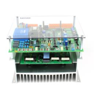
Page 9: Dimensions
Dimensions Controllers of the 480 series without protective cover: R812 ∅ 7mm Explanations ➀ Connecting terminals for field and electronics ➁ Trimmers , I x R, I Leit grob Leit fein ➂ Measuring point "M1" ➃ Spacer "M3" for the attachment of the option boards ➄... -
Page 10: Scope Of Supply
Scope of supply The scope of supply includes: • the controller 48x_E • set-value potentiometer 10 kΩ • the operating instructions Application as directed • The controllers of the types 48x are electrical equipment for the installation into control cabinets of electrical systems or machinery. -
Page 11: Accessories
Accessories The following components can be ordered separately: • RFI filter • Mains choke • Mains fuses and fuse holders • Knob and scale for set-value potentiometer • Option board 2003 and 1071 Type RFI filter Type EZF3_025A001 EZF3_050A001 EZF3_110A001 EZF3_180A001 EZF3_280A001 RFI filter... - Page 12 Mains choke Type Mains choke Type ELN3_0088H035 ELN3_0075H045 ELN3_0038H085 ELN3_0017H170 ELN3_0011H270 L [mH] 3 x 0.88 3 x 0.75 3 x 0.38 3 x 0.165 3 x 0.115 I [A] a [mm] b [mm] c [mm] d [mm] e [mm] f [mm] k [mm] m [mm]...
- Page 13 RFI filter (V = 440 V ±0 %) Design A Design B Type Filter Type EZF3_025A001 EZF3_050A001 EZF3_110A001 EZF3_180A001 EZF3_280A001 Rated current [A] Design a [mm] b [mm] c [mm] d [mm] e [mm] f [mm] g [mm] Fixing 4 x M6 4 x M6 4 x M10 4 x M10...
- Page 14 RFI filter for the separate neutral conductor of the field supply (V = 250 V ±0 %) Design C Type 481 ... 484 Filter Type EZF1_009A001 EZF1_018A001 Rated current [A] Design a [mm] b [mm] c [mm] d [mm] e [mm] 50.8 f [mm] Fixing...
-
Page 15: Installation
Installation Installation When installing into an enclosure ensure sufficient ventilation. The ambient temperature must not exceed +45 °C. Install the controller with the terminals at the top. External operating elements (e.g. switch, fuses) must not be arranged close (≤ 250 mm) to the controller 480. If this distance is not observed, a suitable cover must be provided in order to avoid accidental contact with the controller board. - Page 16 An electrical latching also prevents an automatic reconnection after the controller has cooled. The latching can only be eliminated by disconnection and reconnection of the mains! Notes for the connection of controller and motor Lenze controller Motor (acc. to DIN 42017 / VDE 0530 part 8) Function Termina...
-
Page 17: Installation Corresponding To Emc
• Lenze has done conformity tests with the controllers of the types 48x in certain, defined drive systems. These tested drive systems are called "CE-typical drive system" in the following. -
Page 18: Ce-Typical Drive System
Control cables Screened signal cable type LIYCY Motor DC motor with separate excitation Lenze series GFQ, GFR or similar Note: Controller, RFI filter, and mains choke are located on one mounting plate. Installation of the CE typical drive system The electromagnetic compatibility of a drive system depends on the type and accuracy of the installation. - Page 19 Assembly • Make the contact from controller, RFI filter, and mains chokes to the grounded mounting plate with as large a surface as possible. Zinc-coated mounting plates allow long-lasting contacts. For painted plates the paint of the mounting plates must be removed in all cases. •...
- Page 20 Part of the CE-typical drive system which is located on the mounting plate Connection mains fusing L1 L2 L3 Paint-free bare metal contact sufaces LINE LINE RFI filter Second filter (2-phase) LOAD LOAD Mains choke Paint-free Paint-free surfaces surfaces for for screen contact screen contact Screened...
-
Page 21: Connection Diagram
Connection diagram Feedback Set-value Connections made at the factory input L1.1 L2(N) L1.1 L2.2 L3.2 9 12 14 16 17 31 38 40 Mains filter Tacho F1 F2 F3 =10...180 V Mains filter Master voltage = 10...180 V PE L1 L2 L3 U = 340...460V 50...60Hz = 190...265V 50...60Hz L1, N... -
Page 22: Special Field Voltages
Special field voltages 4.4.1 Field voltage V = 0.9 x V = 340...460 V L1, L2, L3 = 0.9 x U L1 , L2 I, K Example: = 0.9 x 400 V I, K = 360 V I, K 4.4.2 Field connection via autotransformer = 340...460 V L1, L2, L3 = 0.9 x U... -
Page 23: Mains Voltage V 3L < 340 V
Mains voltage V < 340 V L2 L3 L1.1 L2(N) L1.2 L2.2 L3.2 1,1 x U 400V P ≥ 150 VA Mains filter F2 F3 L2 L3 If the mains voltage is lower than 340 V the control electronics must be supplied separately via the step-up transformer as shown in the illustration. -
Page 24: Additional Terminals
Additional terminals Terminal Meaning designation = +15 V= stabilized. +V can be loaded externally with 15 mA. » 10 kΩ, U = 0... –10 V= (–10 V = ^ I Input current controller; R iset Amax = -15 V= stabilized. -V can be loaded externally with 15 mA. -
Page 25: Commissioning
Commissioning Turn trimmers "n ", "n ", "V ", "I · R" fully counterclockwise. Trimmers "U " and "U " are factory-set for the set- Leit grob Leit fein value potentiometer connection as a standard. Only if a master voltage is used: "U "... -
Page 26: Armature Voltage Control With "I X R Compensation
Armature voltage control with "I x R compensation" Caution! In this operating mode all control terminals carry mains potential. It is therefore necessary that all input and output signals required for the control of the controller are safely separated electrically by measures outside the controller and have another protection against direct contact (double basic insulation). -
Page 27: Speed Control With Tacho Feedback
Speed control with tacho feedback Caution! In this operating mode, the control electronics has a simple basic insulation. Take measures outside the controller to ensure that the input and output signals of the control have a double basic insulation. • Set set-value potentiometer or master voltage to zero. Connect mains. -
Page 28: Switching Operation
Switching operation Controller enable If switch "RFR" is closed, the controller is enabled. If the switch "controller enable" (RFR) is open the speed controller is inhibited, i.e. the firing pulses are set to the inverter limit position. 16 17 Only use low-current contacts for the switching of signal cables (15V / 1.5mA) Controller inhibit The function "RSP", i.e. -
Page 29: Index
Index Operating modes Accessories 9 Controller enable 26 Additional terminals 22 Controller inhibit 26 Application as directed 8 Replacing the fuses 22 Commissioning 23 Armature voltage control with "I · R compensation" 24 Scope of supply 8 Setting the current limit 23 Special field voltages 20 Controller features 5 Speed control with tacho feedback 25...
Need help?
Do you have a question about the 482 and is the answer not in the manual?
Questions and answers