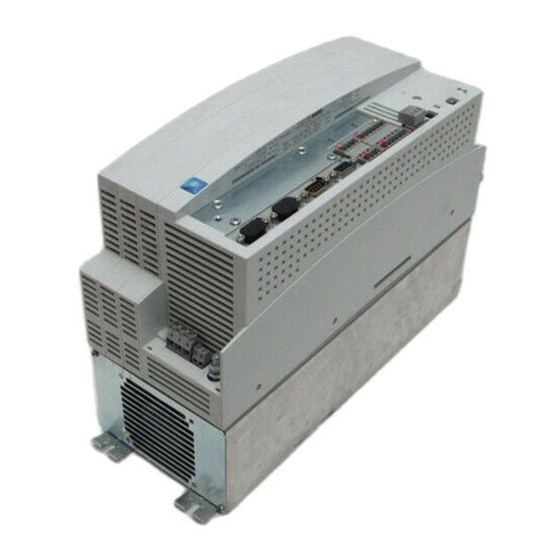
Lenze 9300 System Manual
Servo position controller
Hide thumbs
Also See for 9300:
- Manual (524 pages) ,
- System manual (458 pages) ,
- Operating instructions manual (186 pages)

Related Manuals for Lenze 9300


Summary of Contents for Lenze 9300
- Page 1 Show/Hide Bookmarks EDSVS9332P !.ðv7 System Manual Global Drive 9300 servo position controller...
- Page 2 Show/Hide Bookmarks...
- Page 3 Lenze strives to keep all information to the state of the latest controller version. If you should still find deviations from your System Manual, we kindly ask you to refer to the Operating Instructions included in the scope of supply or to contact your Lenze representative directly.
- Page 4 Show/Hide Bookmarks R D Y I M P I m a x M m a x F a i l 1 2 5 0 r p m M C T R L - N - A C T K35.0002...
- Page 5 Show/Hide Bookmarks EDSVS9332P-A System Manual Part A Contents Preface and general information Global Drive 9300 servo position controller...
- Page 6 © 2004 Lenze Drive Systems GmbH, Hameln No part of these Instructions must be copied or given to third parties without written approval of Lenze Drive Systems GmbH. All indications given in this documentation have been selected carefully and comply with the hardware and software described.
-
Page 7: Table Of Contents
............General safety and application notes for Lenze controllers . - Page 8 Show/Hide Bookmarks Contents Part B 3 Technical data ............Features .
- Page 9 Show/Hide Bookmarks Contents Part C 5 Commissioning ............Before switching on .
- Page 10 Show/Hide Bookmarks Contents Part D2.1 7 Configuration ............Configuration with Global Drive Control .
- Page 11 Show/Hide Bookmarks Contents 7.5.9 Travel profile generator and setpoints ......... . . 7-59 7.5.9.1 Linear ramps (L profile)
- Page 12 Show/Hide Bookmarks Contents 7.5.29 Holding brake (BRK) ............7-126 7.5.29.1 Applying the brake...
- Page 13 Show/Hide Bookmarks Contents 7.5.46 Digital frequency processing (DFSET) ......... . . 7-185 7.5.46.1 Setpoint conditioning with stretching and gearbox factor...
- Page 14 Show/Hide Bookmarks Contents 7.5.71 First order delay element (PT1) ..........7-253 7.5.72 CW/CCW-QSP link (R/L/Q)
- Page 15 Show/Hide Bookmarks Contents Monitoring ..............7-291 7.6.1 Reactions...
- Page 16 Show/Hide Bookmarks Contents Part E 8 Troubleshooting and fault elimination ........Troubleshooting .
-
Page 17: Part A
In the following text used for 93XX Any type of servo position controller (types 9321 ... 9332) Controller 93XX servo position controller Drive system Drive systems with servo position controllers 93XX and other Lenze drive components 1.1.2 What is new? Version Id. No. Modifications 05/97... -
Page 18: Legal Regulations
• The specifications, processes, and circuitry described in these Instructions are for guidance only and must be adapted to your own specific application. Lenze does not take responsibility for the suitability of the process and circuit proposals. • The specifications in these Instructions describe the product features without guaranteeing them. -
Page 19: Ec Directives / Declaration Of Conformity
EMC regulation. In this case, the user himself has to prove the compliance with the CE directives for the installation of a machine. Lenze has already provided evidence of installing CE-typical drive systems and confirmed this by the declaration of conformity to the EMC EC directive. -
Page 20: Ec Low-Voltage Directive
Show/Hide Bookmarks Preface and general information 1.3.3 EC Low-Voltage Directive (73/23/EEC) amended by: CE-mark Directive (93/68/EWG) 1.3.3.1 General • The Low-Voltage Directive applies to all electrical equipment for use with a rated voltage between 50 V and 1000 V AC and between 75 and 1500 V DC under normal ambient conditions, except for e.g. -
Page 21: Ec Directive Electromagnetic Compatibility
EC Directive ”EMC” and the observance of the ”Law on electromagnetic compatibility of devices” can be checked. • Lenze has evaluated the conformity of the controllers in defined drive systems. In the following, these evaluated drive systems are called ”CE-typical drive system”. Therefore the user of the controllers can –... - Page 22 Show/Hide Bookmarks Preface and general information 9300std002 EDSVS9332P-A EN 3.0...
-
Page 23: Ec Machinery Directive
Show/Hide Bookmarks Preface and general information 1.3.5 EC Machinery Directive (98/37/EC) 1.3.5.1 General For the purpose of the Machinery Directive, ”machinery” means an assembly of linked parts or components, at least one of which moves, with the appropriate actuators, control and power circuits, etc., joined together for a specific application, in particular for processing, treatment, moving or packaging of a material. - Page 24 Show/Hide Bookmarks Preface and general information EDSVS9332P-A EN 3.0...
-
Page 25: Safety Instructions
(to: Low-Voltage Directive 73/23/EEC) General Lenze controllers (frequency inverters, servo inverters, DC controllers) can include live and rotating parts - depending on their type of protection - during operation. Surfaces can be hot. Non-authorized removal of the required cover, inappropriate use, incorrect installation or operation, creates the risk of severe injury to persons or damage to material assets. - Page 26 UL systems. The documentation contains special information about UL. Safe standstill Variant V004 of the controller series 9300 and 9300 vector, variant x4x of the controller series 8200 vector and axis module ECSxAxxx support the function ”Safe standstill”, protection against unintentional restart, according to the requirements of Appendix I, No.
-
Page 27: Residual Hazards
The controllers do not offer any protection against these operating conditions. Use additional components for this. Parameter set During parameter set transfer, the control terminals of the 9300 controller can have undefined states! transfer Therefore the plugs X5 and X6 must be removed before transfer. Thus it is ensured that the controller is inhibited and all control terminals have the defined state ”LOW”. - Page 28 Show/Hide Bookmarks Safety instructions EDSVS9332P-A EN 3.0...
-
Page 29: Technical Data
Show/Hide Bookmarks EDSVS9332P-B System Manual Part B Technical data Installation Global Drive 9300 servo position controller... - Page 30 © 2004 Lenze Drive Systems GmbH, Hameln No part of these Instructions must be copied or given to third parties without written approval of Lenze Drive Systems GmbH. All indications given in this documentation have been selected carefully and comply with the hardware and software described.
-
Page 31: Features
Show/Hide Bookmarks Contents Part B 3 Technical data ............Features . -
Page 32: Installation
Show/Hide Bookmarks Technical data Part B Technical data Features • Single axis in narrow design – thus space-saving installation • Power range: 370 W to 75 kW – uniform control module and thus uniform connection for the control cables over the complete power range •... - Page 33 Show/Hide Bookmarks Technical data General data/ operating conditions Field Values Vibration resistance Germanischer Lloyd, general conditions Climatic conditions Class 3K3 to EN50179 (without condensation, average relative humidity 85 %) Permissible temperature ranges during transport: -25 °C ... +70 °C during storage of the controller: -25 °C ... +55 °C during operation of the controller: 0 °C ...
- Page 34 Show/Hide Bookmarks Technical data Rated data 3.3.1 Types 9321 to 9325 Type EVS9321-EP EVS9322-EP EVS9323-EP EVS9324-EP EVS9325-EP Order No. EVS9321-EP EVS9322-EP EVS9323-EP EVS9324-EP EVS9325-EP Type EVS9321-CP EVS9322-CP EVS9323-CP EVS9324-CP EVS9325-CP Order No. EVS9321-CP EVS9322-CP EVS9323-CP EVS9324-CP EVS9325-CP 320 V - 0 % ≤ V ≤...
- Page 35 Show/Hide Bookmarks Technical data 3.3.2 Types 9321 to 9324 with 200 % overcurrent Type EVS9321-EP EVS9322-EP EVS9323-EP EVS9324-EP Rated data for operation at a mains: 3 AC / 400V / 50Hz/60Hz Motor power (4-pole ASM) [kW] 0.37 0.75 [hp] Output power U, V, W (8 kHz) [kVA] Output current (8 kHz) Output current (16 kHz)
- Page 36 Show/Hide Bookmarks Technical data 3.3.3 Types 9326 to 9332 Type EVS9326-EP EVS9327-EP EVS9328-EP EVS9329-EP EVS9330-EP EVS9331-EP EVS9332-EP Order No. EVS9326-EP EVS9327-EP EVS9328-EP EVS9329-EP EVS9330-EP EVS9331-EP EVS9332-EP Type EVS9326-CP EVS9327-CP EVS9328-CP Order No. EVS9326-CP EVS9327-CP EVS9328-CP 320 V - 0 % ≤ V ≤...
- Page 37 Show/Hide Bookmarks Technical data 3.3.4 Fuses and cable cross-sections Type Mains input L1, L2, L3, PE/Motor connection U, V, W Input +UG, -UG Operation without mains filter Operation with mains filter Fuse E.l.c.b. Cable cross-section Fuse E.l.c.b. Cable Fuse Cable cross-section cross-section 9321...
-
Page 38: Mechanical Installation
Show/Hide Bookmarks Technical data 3.3.5 Mains filter Rated data (uk ≈ 6%) Type Lenze order number Rated current Inductance for RFI degree A for RFI degree B 9321 1.5 A 24 mH EZN3A2400H002 EZN3B2400H002 9322 2.5 A 15 mH EZN3A1500H003... - Page 39 Show/Hide Bookmarks Technical data EDSVS9332P-B EN 3.0...
-
Page 40: Important Notes
Show/Hide Bookmarks Installation Installation Mechanical installation 4.1.1 Important notes • Use the controllers only as built-in devices! • If the cooling air contains pollutants (dust, fluff, grease, aggressive gases): – Take suitable preventive measures , e.g. separate air duct, installation of filters, regular cleaning, etc. -
Page 41: Standard Assembly With Fixing Rails Or Fixing Brackets
Show/Hide Bookmarks Installation 4.1.2 Standard assembly with fixing rails or fixing brackets K35.0001c Fig. 4-1 Dimensions for assembly with fixing rails/fixing brackets Type Fig. 9321, 9322 9323, 9324 48.5 9325, 9326 21.5 9327, 9328, 9329 9330 28.5 9331, 9332 748.5 28.5 When using an attachable fieldbus module: Observe the free space required for the connection cables... -
Page 42: Assembly With Thermally Separated Power Stage ("Push-Through Technique
The heatsink of the controllers 9321 ... 9329 can be mounted outside the control cabinet to reduce the heat generated in the control cabinet. For this, you need an assembly frame with seal (can be ordered from Lenze). • Distribution of the power loss: –... - Page 43 Show/Hide Bookmarks Installation Dimensions of the types 9321 to 9326 Fig. 4-2 Dimensions for assembly with thermally separated power stage Type 9321, 9322 112.5 385.5 95.5 365.5 105.5 9323, 9324 131.5 385.5 114.5 365.5 105.5 9325, 9226 169.5 385.5 152.5 365.5 105.5 Assembly cutout...
- Page 44 Show/Hide Bookmarks Installation Dimensions of the types 9327 to 9329 K35.0017 Fig. 4-3 Dimensions for assembly with thermally separated power stage Type 9327, 9328, 9329 280 Cutout Z Type Height Width 338 ±1 238 ±1 20 ±2 259 ±2 20 ±2 359 ±2 9327, 9328, 9329 When using an attachable fieldbus module:...
-
Page 45: Assembly Of Variants
Show/Hide Bookmarks Installation 4.1.4 Assembly of variants Variant EVS932X-Cx (”Cold plate”) For installation in a control cabinet with other heatsinks in ”cold plate technique” (x = order designation; more information on the inner cover page). Dimensions for types 9321-Cx to 9326-Cx K35.0059 Fig. - Page 46 Show/Hide Bookmarks Installation Dimensions for types 9327-Cx and 9328-Cx K35.0056 Fig. 4-5 Dimensions for ” Cold plate” assembly Type 9327-Cx 9328-Cx When using an attachable fieldbus module: Observe the free space required for the connection cables All dimensions in mm EDSVS9332P-B EN 3.0...
- Page 47 Show/Hide Bookmarks Installation • Observe the following points to comply with the technical data: – Ensure sufficient ventilation of the heatsink. – The free space behind the control cabinet back panel must be at least 500 mm. • If you install several controllers in the control cabinet: –...
-
Page 48: Electrical Installation
Show/Hide Bookmarks Installation Electrical installation Information on installation acc. to EMC requirements are included in chapter 4.3. 4.2.1 Protection of persons Danger! All power terminals carry voltage up to 3 minutes after mains disconnection. 4.2.1.1 Residual-current circuit breakers Labelling of RCCBs Meaning AC-sensitive residual-current circuit breaker (RCCB, type AC) Pulse-current sensitive residual-current circuit breaker (RCCB, type A) - Page 49 Show/Hide Bookmarks Installation 4.2.1.2 Isolation The controllers have an electrical isolation (isolating distance) between the power terminals and the control terminals as well as to the housing: • Terminals X1 and X5 have a double basic insulation (double isolating distance, safe electrical isolation to VDE0160, EN50178).
-
Page 50: Protection Of The Controller
– By means of overcurrent relay or temperature monitoring. – We recommend to use a PTC thermistor or thermal contact (NC contact) for motor temperature monitoring. (Lenze three-phase AC motors are provided with thermal contacts as standard). – PTC thermistors or thermal contacts (NC contact) can be connected to the controller. -
Page 51: Interaction With Compensation Equipment
Show/Hide Bookmarks Installation 4.2.5 Interaction with compensation equipment • The controllers take up a very low fundamental reactive power from the supplying AC mains. Therefore compensation is not necessary. • If the controllers are operated on mains with compensation, this equipment must be used with chokes. - Page 52 Show/Hide Bookmarks Installation 4.2.7.1 Mains connection Types 9321 ... 9326 Stop! • Always mount the PE connection and the shield sheet in the described order. The corresponding parts can be found in the assembly kit. • Do not use the clips for strain relief. L3 +UG -UG 9300STD033 Fig.
- Page 53 Show/Hide Bookmarks Installation Types 9327 ... 9332 9300STD034 Fig. 4-8 Recommendation for a mains connection PE threaded bolt Metallically conductive surface Connect mains cable shield with a large surface to mounting plate of control cabinet and fasten with shield clamp (shield clamp is not included in the scope of supply).
- Page 54 By means of recommended DC fuses. • (+UG, -UG) The fuses/fuse holders recommended by Lenze are UL approved. For DC group drives or supply using a DC source: Please observe the notes in part F of the systems manual. Connection of a brake unit When connecting the brake unit to terminals +UG / -UG, please note that the fuses and cross sections indicated in chapter 3.3.4 do not apply to the brake unit.
- Page 55 Show/Hide Bookmarks Installation 4.2.7.2 Motor connection Types 9321 ... 9326 Stop! • Always mount the PE connection and the shield sheet in the described order. The corresponding parts can be found in the assembly kit. • Do not use the clips for strain relief. T1T2 U V W U V W...
- Page 56 Show/Hide Bookmarks Installation Types 9327 ... 9329 Stop! Do not use clips for strain relief. 9300STD030 Fig. 4-10 Proposal for motor connection PE threaded bolt Fasten shield sheet with two M4 screws. Clamp motor cable shield and cable shield for motor temperature monitoring with clip. The shielding of the motor cable is only required to comply with existing standards (e.
- Page 57 Show/Hide Bookmarks Installation Types 9330, 9331 9300STD031 Fig. 4-11 Proposal for motor connection PE threaded bolt Connect motor cable to threaded bolts U, V, W. Observe correct pole connection and maximum motor cable length. Connect motor cable shield with a large surface to shield sheet and fasten with shield clamps and M5 x 12 mm screws. The shielding of the motor cable is only required to comply with existing standards (e.
- Page 58 Show/Hide Bookmarks Installation Type 9332 9300STD032 Fig. 4-12 Proposal for motor connection PE threaded bolt Connect motor cable to threaded bolts U, V, W. Observe correct pole connection and maximum motor cable length. Use cable clamps for strain relief of the motor cables. Fasten cable clamps with M4 12 mm screws. Connect motor cable shield with a large surface to shield sheet and tighten with shield clamps and M5 x 12 mm screws.
- Page 59 Show/Hide Bookmarks Installation Max. permissible cable cross-sections and screw tightening torques: Max. permissible cable Screw-tightening torques cross-sections Shield/ U, V, W, PE T1, T2 U, V, W PE connection T1, T2 Strain relief Type 0.5 ... 0.6 Nm 3.4 Nm 9321 ...
- Page 60 Show/Hide Bookmarks Installation 4.2.7.3 Connection of a brake unit • When connecting a brake unit (brake module with internal brake resistor or brake chopper with external brake resistor) observe the corresponding Operating Instructions in all cases. Stop! • Design the circuit so that, if the temperature monitoring of the brake unit is activated, –...
- Page 61 Show/Hide Bookmarks Installation 4.2.7.4 DC bus connection of several drives Decentralized supply with brake module O F F F 1 0 R F R R F R K35.0113 Fig. 4-13 Decentralized supply for DC-bus connection of several drives Z1, Z2 Mains filter Brake chopper Brake resistor...
- Page 62 Show/Hide Bookmarks Installation Central supply with supply module • When connecting the supply module, the corresponding Operating Instructions must be observed. K35.0114 Fig. 4-14 Central supply for DC-bus connection of several drives Mains supply filter Supply module 3-6) / “ Mains connection” ( 4-13) F1...F6 Protection, see “...
-
Page 63: Control Connections
Show/Hide Bookmarks Installation 4.2.8 Control connections 4.2.8.1 Control cables • Connect control cables to the screw terminals: Max. permissible cable cross-section Screw-tightening torques 1.5 mm 0.5 ... 0.6 Nm (4.4 ... 5.3 lbin) • We recommend a single-ended shielding of all cables for analog signals to avoid signal distortion. - Page 64 Show/Hide Bookmarks Installation 4.2.8.3 Connection of digital signals (X5) Stop! • The maximum permitted voltage difference between X5/39 and the PE of the controller is 50 V. • Limit the voltage difference by means of overvoltage-limiting components or by connecting X5/39 directly to PE.
- Page 65 The external voltage must be able to supply a current 1 A . • The starting current of the external voltage source is not limited by the controller. Thus, Lenze recommends using voltage sources with current limitation or with an internal impedance of Ω...
- Page 66 Show/Hide Bookmarks Installation Terminal assignment Signal type Function Level Technical data Bold print = Lenze setting (C0005 = 20000) Digital inputs LOW: 0 … +3 V X5/28 Controller inhibit (CINH) HIGH = start HIGH: +12 … +30 V X5/E1 Freely assignable Limit switch –...
- Page 67 Show/Hide Bookmarks Installation 4.2.8.4 Connection of analog signals (X6) Stop! • The maximum permitted voltage difference between X5/39 and the PE of the controller is 50 V. • Limit the voltage difference by means of overvoltage-limiting components or by connecting X5/39 directly to PE.
- Page 68 Connection of the analog input signals for external voltage supply Terminal assignment Signal type Function Level Technical data Bold print = Lenze setting (C0005 = 20000) X6/1 Analog input 1 Differential input of master voltage -10 V to +10 V Resolution:...
- Page 69 For the connection to the digital frequency input (X9) or digital frequency output (X10), use prefabricated Lenze cables. Otherwise, only use cables with twisted pairs and shielded cores (A, A / B, B / Z, Z ) (see connection diagram).
- Page 70 Show/Hide Bookmarks Installation STATE-BUS (X5/ST) The STATE-BUS is a controller-specific bus system for simple monitoring in a network of drives: • Controls all drives connected to the network according to the preselected state. • Up to 20 controllers can be connected (total cable length STATE-BUS < 5m). •...
- Page 71 Show/Hide Bookmarks Installation System bus connection (X4) F2 F3 F2 F3 F2 F3 +UG -UG +UG -UG 932X - 933X 932X - 933X 932X - 933X HI LO K35.0123 Fig. 4-22 Wiring system bus Bus terminating resistors 120 Ω (included in the accessory kit) RA1, RA2 •...
- Page 72 Signal level according to ISO 11898 • Up to 63 bus stations are possible • Access to all Lenze parameters • Master functions are integrated into the controller – Data exchange possible between controllers without participation of a master system (current ratio control, speed synchronization, etc.)
- Page 73 Show/Hide Bookmarks Installation 4.2.9 Automation interface (X1) Various modules can be plugged onto the automation interface (X1): • Keypad 9371BB • Fieldbus modules – 210X: Serial interfaces (LECOM) – 211X: INTERBUS modules – 213X: PROFIBUS-DP modules – 217X: System bus (CAN) modules, DeviceNet/CANopen modules Tip! A documentation is enclosed with each module, describing how to apply and handle the module.
-
Page 74: Motor Temperature Monitoring
– Thermostat/normally-closed contact Other monitoring KTY, PTC and TKO do not offer complete protection. To improve the monitoring, Lenze recommends the use of a bimetal relay. Alternative monitoring Comparators (CMP1 ... CMP3) monitor and a time element (TRANS1 ... TRANS4) limits the motor current for small speeds or motor standstill. - Page 75 Connection of a thermistor or PTC thermistor to terminals T1 and T2 and internal connection Tip! • In the prefabricated Lenze system cables for Lenze servo motors the cable for the temperature feedback is already included. The cables are designed for wiring according to EMC.
- Page 76 Show/Hide Bookmarks Installation 4.2.11 Feedback systems Different feedback systems can be connected to the controller: • Resolver feedback (factory setting) • Encoder feedback – Incremental encoder TTL – Sin/cos encoder – Sin/cos encoder with serial communication (single-turn) – Sin/cos encoder with serial communication (multi-turn) Note! •...
- Page 77 • In all configurations predefined under C0005, a resolver can be used as feedback system. An adjustment is not necessary. Note! Use prefabricated Lenze system cables for the resolver connection. Please contact Lenze before you use other resolvers. Features: •...
- Page 78 Encoder connection (X8) An incremental encoder or a sin/cos encoder can be connected to this input. Note! Use the prefabricated Lenze system cable for the encoder connection. • The encoder supply voltage V can be adjusted in the range from 5 V to 8 V under C0421 CC5_E –...
- Page 79 Show/Hide Bookmarks Installation Incremental encoder Features: • Incremental encoders with two 5 V complementary signals shifted by 90 ° can be connected (TTL encoder). – The zero track can be connected (as option). • 9-pole Sub-D female connector • Input frequency: 0 - 500 kHz •...
-
Page 80: Installation Of A Ce-Typical Drive System
Show/Hide Bookmarks Installation Installation of a CE-typical drive system • General notes The electromagnetic compatibility of a machine depends on the type of installation and care taken. Please observe: – Assembly – Filters – Shielding – Earthing • For diverging installations, the conformity to the CE EMC Directive requires a check of the machine or system regarding the EMC limit values. - Page 81 Show/Hide Bookmarks Installation F1 ... F3 F4 F5 932X - 933X 9351 E1 E2 E3 E4 E5 A1 A2 K35.0124 Fig. 4-26 Example for wiring in accordance with EMC regulations 3-6) / “ Mains connection” ( 4-13) F1...F5 Protection, see “ Cable protection” ( Mains contactor For mains filter “...
- Page 82 Show/Hide Bookmarks EDSVS9332P-C System Manual Part C Commissioning During operation Global Drive 9300 servo position controller...
- Page 83 © 2004 Lenze Drive Systems GmbH, Hameln No part of these Instructions must be copied or given to third parties without written approval of Lenze Drive Systems GmbH. All indications given in this documentation have been selected carefully and comply with the hardware and software described.
- Page 84 Show/Hide Bookmarks Contents Part C 5 Commissioning ............Before switching on .
-
Page 85: Part C
Initial switch-on Tip! • Use a PC with the Lenze program ”Global Drive Control” (GDC) under Windows for commissioning. The convenient menu includes the codes for the most important settings. • A fieldbus module type 2102 ”RS232, RS485, fibre optics” (Lecom A/B) is required to run the GDC. - Page 86 Show/Hide Bookmarks Commissioning Commissioning using an example F1...F3 +UG -UG 93XX Lenze Global Drive Lenze LECOM A/B Control RS485 59 39 71 72 88 89 RS232 28 E1 E2 E3 E4 E5 A1 A2 A3 A4 59 Fig. 5-1 Example of a drive control with default setting...
- Page 87 Show/Hide Bookmarks Commissioning The following table briefly shows how to commission a position control according to the example depicted in Fig. 5-1. A more detailed description of how to commission position controls can be obtained from the following chapters. Section Action Detailed description...
-
Page 88: Commissioning Sequence
Show/Hide Bookmarks Commissioning Commissioning sequence Switch on controller Chapter 5.4 Switch on PC, start GDC Chapter5.5 Parameter set already generated? Load A positioning already used Generate A new positioning parameter set parameter set is to be set up again is to be entered Chapter 5.9 Chapter 5.6 Adapt controller to the... -
Page 89: Switch On Controller
The controller inhibit is evaluated, among other things, by the ”holding brake (BRK)” (see chapter in the corresponding 9300 System Manual). *) C0172 = ”OV reduce - Threshold for activating the brake torque reduction before OU message”... -
Page 90: Switch On Pc, Start Gdc
Show/Hide Bookmarks Commissioning Switch on PC, start GDC • Switch on PC. • Start the GDC program under Windows. When GDC is in ”online operation” • The ”Find LECOM A/B drives” dialog box is opened. • Click ”Find”. GDC will now search for a controller. •... -
Page 91: Generate Parameter Set
Show/Hide Bookmarks Commissioning Generate parameter set Warning! Do not change any settings of the controller that are not mentioned in this chapter. For more complex positioning tasks use the System Manual. The instructions for the generation of a parameter set in this chapter are based on the default setting. Proceed systematically when generating a parameter set: 1. -
Page 92: Adapt Controller To The Motor
Resolver error. Enter the value of the motor nameplate. Select C0003 Save data (C0003 = 1). If you use a motor other than the Lenze motor: Change to the menu ”Motor setting” (see Fig. 5-4). In the menu ”Motor setting”:... -
Page 93: Enter Machine Parameters
Show/Hide Bookmarks Commissioning 5.6.3 Enter machine parameters Fig. 5-5 ” Basic settings” dialog box Field Command Function Click on field ”Gearbox numerator” Enter denominator for the gearbox ratio. Motor Motor Click on field ”Gearbox denominator” Enter numerator for the gearbox ratio. Gearbox output Click on field ”Feed constant”... -
Page 94: Parameters For Manual Control
Show/Hide Bookmarks Commissioning 5.6.4 Parameters for manual control Stop! Check the parameters for manual control. In order to check a configuration select small values for acceleration and deceleration (e. g. default setting). The default setting of the parameters is sufficient for most of the application cases. Enter the setting as follows: Fig. -
Page 95: Controller Enable
Show/Hide Bookmarks Commissioning 5.6.5 Controller enable • The controller is only enabled if all sources of controller inhibit are reset. – When the controller is enabled, the green LED on the controller is illuminated. • For displaying active sources of a controller inhibit see chapter ”Troubleshooting” 8-1) The following table shows the conditions for controller enable: Source controller inhibit... -
Page 96: Function Test With Manual Control
Show/Hide Bookmarks Commissioning Function test with manual control Test the function with manual control after every new or modified configuration. Warning! Provide suitable emergency stops for manual operation so that you will be able to stop the drive in the event of unpredictable movements. 9300pos041 Fig. - Page 97 Show/Hide Bookmarks Commissioning 9300pos041 Fig. 5-8 Dialog box ” Control” Field Command Function Select ”Negative manual” The drive positions in the negative direction towards the limit switch. • Test positioning limits • Override travel range limit switch to test its function. Reset ”Negative manual”...
-
Page 98: Enter Travel Profile Parameters
Show/Hide Bookmarks Commissioning Enter travel profile parameters 5.8.1 Structure of a positioning program • The positioning program consists of max. 32 program sets (PS). • The sequence of processing the PS within the positioning program can be freely selected. • The positioning sequence is determined by the PS. -
Page 99: Tools For Editing
Show/Hide Bookmarks Commissioning 5.8.1.1 Tools for editing For a quick and easy entry of the parameter data the GDC makes tools for editing available to the user. These are explained with the help of the PS templates that are displayed in the operating program. Fig. -
Page 100: Structure Of A Travel Profile
Show/Hide Bookmarks Commissioning 5.8.1.2 Structure of a travel profile • Make a travel profile of your drive task (e. g. B. Fig. 5-11, Fig. 5-12) • For more complex positioning profiles, generate the positioning program with several PS (e.g. for different positioning speeds). PS 01 PS 02 PS 03... - Page 101 Show/Hide Bookmarks Commissioning V T A C C V T V E L V T A C C V T V E L V T A C C V T V E L V T A C C V T A C C S t a r t i n g E n d p o s i t i o n p o s i t i o n...
- Page 102 Show/Hide Bookmarks Commissioning Description of the input template <End Sub>Click on the ”Programming” button in the ”Basic settings” dialog box. Fig. 5-13 Dialog box for entering the positioning data Field Function Description Dialog box for a program set All necessary positioning profile parameters for a PS are entered as well as possible branches to (PS) further PS.
- Page 103 Show/Hide Bookmarks Commissioning Processing a program set The following chart shows the processing of a program set (PS). 1 1 1 1 Waiting Input signal (PFI) active? released? ”Switching before pos.” Switching Will output PFO xx be set? active? ”if PS-CANCEL or no TP” select PS PS mode Select Positioning completed?
-
Page 104: Enter Parameter
Show/Hide Bookmarks Commissioning 5.8.1.3 Enter parameter Fig. 5-15 Dialog box for entering the positioning data Field Function Description Inactive or no. of a PFI Program function input (PFI). A digital input signal via an FB or terminal starts the PS processing. -
Page 105: Saving A Parameter Set
Show/Hide Bookmarks Commissioning 5.8.2 Saving a parameter set The operating menu GDC (see Fig. 5-16) allows you to save a new or modified parameter set: • Saving on the hard disk of the PC or a diskette by ”Write all parameter sets to file” •... -
Page 106: Load Parameter Set
Show/Hide Bookmarks Commissioning Load parameter set 5.9.1 Load parameter set from the PC The operating menu (Fig. 5-17) enables the parameter set to be loaded • from the hard disk of the PC or a diskette in GDC by ”Read all parameter sets from file”, •... -
Page 107: Load Parameter Set From The Controller
Show/Hide Bookmarks Commissioning 5.9.2 Load parameter set from the controller The operating menu (Fig. 5-17) enables the parameter set to be loaded • from the controller to the PC by ”Read current parameter set from the controller (F7)” – C0002 offers the following options in the menu ”Parameter set management”: 1. -
Page 108: Control Drive
Show/Hide Bookmarks Commissioning 5.10 Control drive 5.10.1 Description of the dialog box • Click on the ”Control” button in the ”Basic settings” dialog box. 9300pos043 Fig. 5-18 Dialog box ” Control” Field Function Description Manual control 5-12 Manual homing 5-26 Menu ”Diagnostics”... -
Page 109: Parameters For Homing
Show/Hide Bookmarks Commissioning 5.10.2 Parameters for homing Fig. 5-19 Menu ” Homing” in the parameter menu The default setting of the parameters is sufficient for most of the application cases. Enter the setting as follows: Step Command Function Select ”Basic settings” dialog box. Click on ”Parameter menu”... -
Page 110: Manual Homing
Show/Hide Bookmarks Commissioning 5.10.3 Manual homing The controller can perform all positioning tasks only with a defined reference point (zero point). • Click on the ”Control” button in the ”Basic settings” dialog box. 9300pos044 Fig. 5-20 Dialog box ” Control” Field Command Function... -
Page 111: Program Control
Show/Hide Bookmarks Commissioning 5.10.4 Program control 9300pos045 Fig. 5-21 Dialog box ” Control” Field Command Function Activate program operation For default setting • Switch terminal X5/E5 = HIGH. Reset ”Manual operation”. Manual operation switched off. With drive status ”OK”, ”Start” is possible. Controller ”Start”... -
Page 112: Automatic Control Parameter Identification
Show/Hide Bookmarks Commissioning 5.11 Automatic control parameter identification The function “Automatic control parameter identification” serves to • identify mechanical distance parameters by a short motion run and • automatically set the speed and position encoder based on the parameters identified or selected. -
Page 113: Procedure
Show/Hide Bookmarks Commissioning 5.11.1 Procedure A c t i v a t i n g m o d e = 1 , 2 , 3 M o d e = 1 ? P r e p a r e m o v e m e n t R S P = 0 ? y e s A c c e p t m e a s u r e d... -
Page 114: Troubleshooting
Show/Hide Bookmarks Commissioning Calculation of control parameters (Mode = 1) This function only calculates control parameters. Identification/Identification and calculation of control parameters (mode = 2 / 3) By activating the function “Identification” or ”Identification and Calculation of control parameters” a motion of the drive is released. Reset the controller inhibit (CINH) to release the motion after the function has been activated. -
Page 115: Password Protection
Show/Hide Bookmarks Commissioning 5.11.2.1 Password protection Possible settings Code IMPORTANT Lenze Selection C0094 Password 9999 Password • Parameter access protection for the operating module. When the password is activated, only the codes of the user menus can be accessed. For further possible selections see C0096... - Page 116 Show/Hide Bookmarks Commissioning 5-32 EDSVS9332P-C EN 3.0...
-
Page 117: During Operation
Show/Hide Bookmarks During operation During operation Status indications 6.1.1 Display on the controller Two LEDs at the front of the controller indicate the controller status. LED green LED red Cause Check Controller enabled; no fault Controller inhibit, switch-on inhibit C0183; or C0168/1 Fail C0168/1 Warning, fail-QSP... -
Page 118: Display In Global Drive Control
Display in Global Drive Control 1. Click on the ”Control” button in the ”Basic settings” dialog box. 2. Click on the ”Diagnostics” button in the ”Control” dialog box. Fig. 6-1 ” Diagnostic 9300” dialog box Type of fault Actual speed Actual motor voltage... -
Page 119: Actual Value Display Via Codes
Show/Hide Bookmarks During operation 6.1.4 Actual value display via codes You can read different actual values using the following codes: Code Meaning C0051 Absolute actual speed [rpm] C0052 Absolute motor voltage [V] C0053 Absolute DC bus voltage [V] C0054 Absolute motor current [A] C0060 Rotor position [Inc/rev] C0061... -
Page 120: Controller Protection By Current Derating
Show/Hide Bookmarks During operation 6.2.2 Controller protection by current derating Valid for the types 9326 to 9332. For rotating-field frequencies < 5 Hz the controller automatically derates the maximum permissible output current. • For operation with switching frequency = 8 kHz (C0018=1, power-optimised): –... - Page 121 Show/Hide Bookmarks EDSVS9332P-D21 System Manual Part D2.1 Configuration Global Drive 9300 servo position controller...
- Page 122 © 2004 Lenze Drive Systems GmbH, Hameln No part of these Instructions must be copied or given to third parties without written approval of Lenze Drive Systems GmbH. All indications given in this documentation have been selected carefully and comply with the hardware and software described.
- Page 123 Show/Hide Bookmarks Contents Part D2.1 7 Configuration ............Configuration with Global Drive Control .
- Page 124 Show/Hide Bookmarks Contents 7.5.9 Travel profile generator and setpoints ......... . . 7-59 7.5.9.1 Linear ramps (L profile)
- Page 125 Show/Hide Bookmarks Contents 7.5.29 Holding brake (BRK) ............7-126 7.5.29.1 Applying the brake...
- Page 126 Show/Hide Bookmarks Contents 7.5.46 Digital frequency processing (DFSET) ......... . . 7-185 7.5.46.1 Setpoint conditioning with stretching and gearbox factor...
- Page 127 Show/Hide Bookmarks Contents 7.5.70 Phase integrator (PHINT) ........... . 7-250 7.5.70.1 Constant input value...
- Page 128 Show/Hide Bookmarks Contents 7.6.3 Monitoring functions ............7-293 7.6.3.1 System fault CCr...
-
Page 129: Part D2.1
7-7) Configuration with Global Drive Control With Global Drive Control (GDC), LENZE offers an easy-to-understand, clearly-laid-out and convenient tool for the configuration of your specific drive task. Function block library GDC provides an easy-to-read library of available function blocks (FB). -
Page 130: Changing The Basic Configuration
Show/Hide Bookmarks Configuration 7.1.1 Changing the basic configuration If the basic configuration must be changed for a special application, proceed as follows: 1. Select a basic configuration via C0005 which largely meets the requirements. 2. Add functions by: – Reconfigure inputs and/or outputs. –... -
Page 131: Operating Modes
Show/Hide Bookmarks Configuration Operating modes Determine the operating mode, the interface you want to use for parameter setting or control of the controller, by choosing an operating module. 7.2.1 Parameter setting Parameters can be set with one of the following modules: •... -
Page 132: Signal Types
Show/Hide Bookmarks Configuration 7.2.3 Signal types Each function block is provided with a certain number of inputs and outputs which can be interlinked. Corresponding to its respective function only particular signal types occur at the inputs and outputs: • Quasi analog signals –... -
Page 133: Elements Of A Function Block
Show/Hide Bookmarks Configuration 7.2.4 Elements of a function block Parameterisation code Input name FB name FCNT1 C1100 FCNT1-CLKUP FCNT1-OUT C1102/1 C1104/1 FCNT1-CLKDWN Output symbol C1102/2 C1104/2 CTRL Input symbol FCNT1-EQUAL FCNT1-LD-VAL C1101/1 C1103/1 FCNT1-LOAD C1102/3 C1104/3 FCNT1-CMP-VAL C1101/2 C1103/2 Configuration code Function Display code Output name... - Page 134 Show/Hide Bookmarks Configuration Configuration code Configures the input with a signal source (e. g. terminal signal, control code, output of an FB, ...). Inputs with identical codes are distinguished by the attached subcode (Cxxxx/1). These codes are configured via the subcode. It is not possible to connect an input with several signal sources.
-
Page 135: Connection Of Function Blocks
Show/Hide Bookmarks Configuration 7.2.5 Connection of function blocks General rules • Assign a signal source to an input. • One input can have only one signal source. • Inputs of different function blocks can have the same signal source. • Only the same types of signals can be connected. - Page 136 Show/Hide Bookmarks Configuration Basic procedure 1. Select the configuration code of the function block input which is to be changed. 2. Determine the source of the input signal for the selected input (e.g. from the output of another function block). 3.
- Page 137 Show/Hide Bookmarks Configuration Establish connections 1. Determine the signal source for ARIT2-IN1: – Change to the code level using the arrow keys – Select C0601/1 using or . – Change to the parameter level using PRG. – Select output AIN2-OUT (selection number 55) using or .
- Page 138 Show/Hide Bookmarks Configuration Remove connections • Since a source can have several targets, there may be further signal connections, which may not be wanted. • Example: – In the default setting of the basic configuration C0005 = 1000 (speed control), ASW1-IN1 and AIN2-OUT are connected.
-
Page 139: Entries Into The Processing Table
Show/Hide Bookmarks Configuration 7.2.6 Entries into the processing table The 93XX controller provides a certain time for calculating the processing time of FBs. Since the type and number of FBs to be used depends on the application and can vary strongly, not all available FBs are permanently calculated. - Page 140 Show/Hide Bookmarks Configuration 5. The entries in C0465 are: – Position 10: AND1 10500 – Position 11: OR1 10550 – Position 12: AND2 10505 This example was started with position 10, because these positions are not assigned in the default setting.
-
Page 141: Signal Configuration With Global Drive Control
Show/Hide Bookmarks Configuration 7.2.6.1 Signal configuration with Global Drive Control Fig. 7-6 Dialog field “ Signal configuration of servo positioning controller 9300” Field Command Function Initiate parameter menu Open menu “Dialog signal configuration”. Click “Configuration”. All signal configurations available are displayed in a window. -
Page 142: Terminal Assignment
Show/Hide Bookmarks Configuration Terminal assignment If you change the signal configuration via C0005, the assignment of all inputs and outputs will be overwritten with the corresponding basic assignment. If necessary, adapt the function assignment to your wiring. • The digital inputs are linked via the FB DIGIN. 7-192) •... -
Page 143: Freely Assignable Digital Inputs
Show/Hide Bookmarks Configuration 7.3.1 Freely assignable digital inputs Five freely assignable inputs are available (X5/E1 ... X5/E5). The signals are conditioned and linked with other FBs via FB DIGIN. 7-192) Display links: Fig. 7-7 Dialog box “ Terminal I/O (digital)” Field Command Function... -
Page 144: Freely Assignable Digital Outputs
Show/Hide Bookmarks Configuration 7.3.2 Freely assignable digital outputs Four freely assignable outputs are available (X5/A1 ... X5/A5). The signals are conditioned and linked with other FBs via FB DIGOUT. 7-193) Change assignment: Fig. 7-8 Dialog box “ Terminal I/O (digital)” Field Command Function... -
Page 145: Input And Outputof The State-Bus
Show/Hide Bookmarks Configuration 7.3.3 Input and outputof the STATE-BUS Configure input and output of the FB STATE-BUS. 7-267) Change assignment: Fig. 7-9 Dialog box “ Terminal I/O (digital)” Field Command Function Initiate parameter menu Click on “Dialog terminal I/O (digital)” menu. -
Page 146: Freely Assignable Analog Inputs
Show/Hide Bookmarks Configuration 7.3.4 Freely assignable analog inputs Two freely assignable analog inputs are available (X6/1,2 and X6/3,4). The signals are conditioned and linked with other FBs via FB AIN. 7-101) Display links: Fig. 7-10 Dialog box “ Terminal I/O 93xx (analog)” Field Command Function... -
Page 147: Freely Assignable Analog Outputs
Show/Hide Bookmarks Configuration 7.3.5 Freely assignable analog outputs Two freely assignable analog outputs are available (X6/62 and X6/63). The signals are conditioned and linked with other FBs via FB AOUT. 7-107) Change assignment: 4 5 6 Fig. 7-11 Dialog box “ Terminal I/O 93xx (analog)” Field Command Function... -
Page 148: System Bus (Can-In)
Show/Hide Bookmarks Function library Description of the function blocks Function blocks Function block Description CPU time used in base configuration C0005 [µ µ µ µ s] 1000 20000 22000 26000 ABS1 Absolute value generator 7-94 ADD1 Adding block 7-95 AIF-IN Fieldbus 7-96 •... - Page 149 Show/Hide Bookmarks Function library Function block Function block Description Description CPU time CPU time used in base configuration C0005 [µ µ µ µ s] [µ µ µ µ s] 1000 20000 22000 26000 CONVAPH1 Analog phase converter 1 7-157 CONVAPH2 Analog phase converter 2 CONVAPH3 Analog phase converter 3...
- Page 150 Show/Hide Bookmarks Function library Function block Function block Description Description CPU time CPU time used in base configuration C0005 [µ µ µ µ s] [µ µ µ µ s] 1000 20000 22000 26000 PHDIV1 Conversion 7-249 PHINT1 Phase integrator 7-250 •...
- Page 151 Show/Hide Bookmarks Function library Code Code Description Description CPU time CPU time [µ µ µ µ s] [µ µ µ µ s] FCODE 472/8 FCODE 472/9 FCODE 472/10 FCODE 472/11 FCODE 472/12 FCODE 472/13 FCODE 472/14 FCODE 472/15 FCODE 472/16 FCODE 472/17 FCODE 472/18 FCODE 472/19...
-
Page 152: Positioning Control (Pos)
Function library Positioning control (POS) Purpose The function block ”positioning control (POS)” is the core of the 9300 servo position controller. It controls positioning in the controller. P O S - S T A R T - P S C 1 3 6 2 / 1... - Page 153 Show/Hide Bookmarks Function library Signal Source Note Designation Type DIS format List POS-A-OVERRID C1363/3 dec [%] C1362/3 Reduces the acceleration and deceleration as well as the manual traversing acceleration and homing acceleration. Note: Only positive override values are effective, negative values will be evaluated as zero.
- Page 154 Show/Hide Bookmarks Function library Signal Source Note Designation Type DIS format List POS-MOUT Current torque precontrol value after influence of POS-MOUT-GAIN. Scaling: 100% acc. to a-max (C1250). POS-MOUT-GAIN C1363/7 dec [%] C1362/7 Reduces torque precontrol. The polarity of the input signal is considered. POS-N-IN C1363/4 dec [%]...
- Page 155 Show/Hide Bookmarks Function library Signal Source Note Designation Type DIS format List POS-RESETED Position status display HIGH = Position program in status “Prg-Reset” (see “program control” 7-71) POS-RUNNING Position status display POS-RUNNING = HIGH: Program run is started and is not interrupted by controller inhibit, faults or manual control.
- Page 156 Show/Hide Bookmarks Function library Formulae for scaling the signals (see preceding table, column ”Note”): Formula 1: Position 65536 [inc∕Umdr] ⋅ gear nominator = Position ⋅ 65536 ⋅ C1202 Position [inc] = Position [units] ⋅ C1204 ⋅ C1203 Feed const. [units∕Umdr] ⋅ gear denominator Formula 2: Speed (VEL) 65536 [inc∕Umdr] ⋅...
- Page 157 Show/Hide Bookmarks Function library Function • Dimensions 7-30) • Machine parameters 7-31) • Positioning mode “Relative Positioning” 7-35) • Positioning mode “Absolute Positioning” 7-37) • Measuring systems 7-39) • Absolute positioning with saving 7-38) • Absolute positioning through encoder connection X8 7-42) •...
-
Page 158: Dimensions
Show/Hide Bookmarks Function library 7.5.1 Dimensions Absolute dimensions An absolute target position is a defined position on the traversing path with reference to a zero point. The target position is approached irrespective of the current position. P 2 ( X 2 ) P 1 ( X 1 ) P 3 ( X 3 ) A b s o l u t e d i m e n s i o n s... -
Page 159: Machine Parameters
Show/Hide Bookmarks Function library 7.5.2 Machine parameters Example Purpose • The physical unit (e.g.: mm, m, degree) is defined by entering the machine parameters (see Part C, chapter 5.6.1). Function • Input of the gear ratio under C1202 and C1203, according to the nameplate data of the gearbox. - Page 160 Show/Hide Bookmarks Function library Application example For positioning a spindle feeding unit is driven via a gearbox. An incremental encoder is used instead of the standard resolver as feedback system. The incremental encoder is mounted to the motor and has a number of increments of 4096 pulses / rev. The gearbox has a ratio of i = 32 (n motor spindle The spindle has a lead of h = 10 mm.
-
Page 161: Position Encoder At Material Path
Show/Hide Bookmarks Function library 7.5.2.1 Position encoder at material path Purpose The gearbox backlash and the slip between drive, machine, and material should be eliminated to increase the accuracy of the calculation of an act. position value. Function • The feedback is ensured by a separate position encoder (C0490) at the material web. •... - Page 162 Show/Hide Bookmarks Function library Example (refers to the preceding safety information): With a quadruple evaluation of a position encoder with 1024 increments 4096 increments are available. The angle of rotation of the motor shaft per encoder increment: 360° = 0.0879 ° = 0° 5.3′ (5.3 angular minutes ) 4096 incr Ratio of the position encoder e.g.
-
Page 163: Positioning Modes (C1210)
Show/Hide Bookmarks Function library 7.5.3 Positioning modes (C1210) You can select the following positioning modes under C1210: • Relative positioning 7-35) • Absolute positioning 7-37) • Absolute positioning with saving 7-38) 7.5.3.1 Relative positioning Purpose • Use with infinite applications, e.g. a cutter. Function •... - Page 164 Show/Hide Bookmarks Function library Position resolution • Display via code C1205. Display of the number of increments with which the units defined by the user are resolved (incr/unit). • The position resolution can be used to check for rounding errors. Calculation example: C1301/1 = 100.2550 units (position value in VTPOS) C1205 = 80.0000 inc/unit (position resolution)
-
Page 165: Absolute Positioning
Show/Hide Bookmarks Function library 7.5.3.2 Absolute positioning P O S - L I M - N E G P O S - R E F - M A R K P O S - L I M - P O S C 1 2 2 4 C 1 2 2 3 L i m i t p o s i t i o n... -
Page 166: Absolute Positioning With Saving
Show/Hide Bookmarks Function library 7.5.3.3 Absolute positioning with saving Purpose Homing is not necessary after mains switching. Function • Resolver or absolute value encoder (single-turn) to X8 is required as position feedback system. • Set positioning mode (C1210) = 2 (absolute positioning with saving). •... -
Page 167: Measuring Systems
Show/Hide Bookmarks Function library 7.5.4 Measuring systems Purpose • Limitation of the traversing and determination of reference points for positioning. T r a v e r s i n g r a n g e E n d o f t r a v e l s w i t c h E n d o f t r a v e l s w i t c h "... -
Page 168: Measuring Systems And Zero Shifts
Show/Hide Bookmarks Function library 7.5.4.1 Measuring systems and zero shifts 9300POS007 Fig. 7-18 Measuring systems for absolute positioning and zero point shifting Shifting of machine zero Purpose • The reference run is to be carried out on one side of the traversing range when it is too time consuming to approach the machine zero. -
Page 169: Measuring Systems For Absolute Value Encoders
Show/Hide Bookmarks Function library 7.5.4.2 Measuring systems for absolute value encoders ( I n p u t : n e g . v a l u e ) D i s p l a y r a n g e a b s o l u t e v a l u e e n c o d e r ( C 1 2 2 0 / 5 ) ( O v e r f l o w ) 9300POS008 Fig. -
Page 170: Absolute Value Encoder Via Encoder Connection X8
Show/Hide Bookmarks Function library 7.5.5 Absolute value encoder Purpose The absolute actual position value should be known immediately after mains switching so that homing is not necessary (for instance if homing is not possible because of machining or processing circumstances). •... - Page 171 Show/Hide Bookmarks Function library Installation The absolute value encoder must be mechanically mounted so that the encoder zero point is outside the travel range. Otherwise a value overflow would occur in the encoder within the travel range. This would result in a wrong actual position value after mains switching. Commissioning Observe the commissioning sequence to avoid a reset of C0420 to default setting.
-
Page 172: Absolute Value Encoder Via System Bus (Can)
Show/Hide Bookmarks Function library 7.5.5.2 Absolute value encoder via system bus (CAN) Purpose • Using absolute value encoders with CAN interface (e. g. laser measuring system). t r a n s m i t t e d a b s o l u t e F C O D E - C 4 7 3 / 4 C O N V P H P H 2 - N U M e n c o d e r v a l u e... - Page 173 Show/Hide Bookmarks Function library Example for the adaptation of the encoder resolution: Gearbox between encoder and drive i = 30 Effective wheel diameter d = 50 mm Position resolution of the measuring system = 8 inc/mm meas Internal position resolution (fix) = 65536 inc/rev internal Position resolution of the measuring system (with regard to motor side):...
-
Page 174: Control Structure
Show/Hide Bookmarks Function library 7.5.6 Control structure The following graph provides an overview of the control structure realised in the 9300 servo position controller. It shows the parameters and codes that are decisive for the adjustment of the control loops. 9300POS039 Adjustment points of the control loops •... -
Page 175: Travel Range Limits
Show/Hide Bookmarks Function library 7.5.7 Travel range limits You can prevent the mechanical stops of the limited travel range from being touched by • the travel range limit switches (hardware), • the position limiting values (software). P O S - L I M - N E G P O S - R E F - M A R K P O S - L I M - P O S C 1 2 2 4... -
Page 176: Position Limit Values (C1223, C1224)
Show/Hide Bookmarks Function library 7.5.7.2 Position limit values (C1223, C1224) • Position limit values (C1223, C1224) define the permissible traversing range of the drive. • The reference point for the position limiting values always is the machine zero point. Shifting the real zero point does not result in a shift of the position limiting value with the regard to the mechanical travel range limits. -
Page 177: Homing
Show/Hide Bookmarks Function library 7.5.8 Homing Determination of the mechanical reference point for measuring systems. After homing, the drive is in a defined position. Functions • Homing 7-49) • Homing end 7-50) • Homing status 7-51) • Homing modes 7-52) •... -
Page 178: Homing End
Show/Hide Bookmarks Function library 7.5.8.2 Homing end Purpose • Determination of the point where the drive is going to stop after homing. • Avoid reversing while homing Selection of the homing limit (C1209) • C1209 = 0 (default setting): Drive stops at reference point (index pulse / zero position / touch probe) or returns to that point. -
Page 179: Referencing Status (Pos-Ref-Ok)
Show/Hide Bookmarks Function library 7.5.8.3 Referencing status (POS-REF-OK) The referencing status is indicated via the function block output “POS-REF-OK” and displayed under C1284. The referencing status is displayed as ”Reference known” when the measuring systems have a defined reference to the machine. Absolute positioning is only possible after a 7-37) 7-38) -
Page 180: Homing Mode 0 And 1
Show/Hide Bookmarks Function library 7.5.8.4 Homing mode 0 and 1 Purpose • Simple homing in all positioning modes (C1210 = 0, 1, 2). • The homing switch (POS-REF-MARK) must be in direction of the movement. Move to reference point via homing switch Mode 0: Traversing direction to positive end of travel range limit switch Set C1213 = 0. -
Page 181: Homing Mode 2 And 3
Show/Hide Bookmarks Function library 7.5.8.5 Homing mode 2 and 3 Purpose • Homing in absolute positioning mode (C1210 = 0, 2), with finite traversing range and existing travel range limit switches (POS-LIM-xxx). • The homing switch (POS-REF-MARK) is always found. In worst case the entire traversing range will be searched. -
Page 182: Homing Mode 4 And 5
Show/Hide Bookmarks Function library 7.5.8.6 Homing mode 4 and 5 Purpose • Simple homing in all positioning modes (C1210 = 0, 1, 2). • The homing switch (POS-REF-MARK) will not be overridden. Positions to the right of the homing switch cannot occur due to the mechanical design. •... -
Page 183: Homing Mode 6 And 7
– C1214 = 1 ≙ Terminal X5/E1. – C1214 = 2 ≙ Terminal X5/E2. – C1214 = 3 ≙ Terminal X5/E3. – C1214 = 4 ≙ Terminal X5/E4 (this setting is recommended by LENZE). • Select edge of the TP input via C1215. -
Page 184: Homing Mode 8 And 9
– C1214 = 1 ≙ Terminal X5/E1. – C1214 = 2 ≙ Terminal X5/E2. – C1214 = 3 ≙ Terminal X5/E3. – C1214 = 4 ≙ Terminal X5/E4 (this setting is recommended by LENZE). • Select signal of the TP input via C1215/x. -
Page 185: Homing Mode 10 And 11
Show/Hide Bookmarks Function library 7.5.8.9 Homing mode 10 and 11 Purpose • Homing in absolute positioning mode (C1210 = 0, 2). • Use of touch probe if the index pulse does not appear at the same place in a reproducible form due to the mechanical constellation. -
Page 186: Second Homing Speed
Show/Hide Bookmarks Function library 7.5.8.10 Second homing speed Second homing speed A second homing speed (C1241) can be activated by C1216. Homing procedure with activated second homing speed: Mode 0, 1: To POS-REF-MARK at first speed, then at second speed. Mode 2, 3: At first speed to limit switch POS-LIM-POS (mode 2) or POS-LIM-NEG (mode 3), second speed after reversing. -
Page 187: Travel Profile Generator And Setpoints
Show/Hide Bookmarks Function library 7.5.9 Travel profile generator and setpoints P O S - R E F - O K S E T P O S P O S - I N - T A R G E T & T A R G E T P O S - V T R A V - R E A P O S - W A I T S T A T E... -
Page 188: Linear Ramps (L Profile)
Show/Hide Bookmarks Function library Function • Linear ramps (L profile) 7-60) • S ramps (S profile) 7-61) • Override (POS-V-OVERRID, POS-A-OVERRID) 7-63) • New traversing profile parameters during positioning (POS-PARAM-RD) 7-59) • Influence of precontrol values (POS-NOUT-GAIN, POS-MOUT-GAIN) 7-63) • Target window (POS-WAITSTATE) 7-65) •... -
Page 189: S Ramps (S Profile)
Show/Hide Bookmarks Function library 7.5.9.2 S ramps (S profile) Purpose Protection from damage of the drive components by reducing the jerk during acceleration and deceleration. VTVEL = Traversing speed + VTACC = Acceleration - VTACC = Select deceleration 9300pos002 Fig. 7-29 S ramps (S profile) 1. - Page 190 Show/Hide Bookmarks Function library qÜÉ p éêçÑáäÉ ãìëí ÄÉ ~Åíáî~íÉÇ ÄÉÑçêÉ ëí~êíáåÖ éçëáíáçåáåÖK • p éêçÑáäÉ áë ~Åíáî~íÉÇ ~ë ÑçääçïëW • `çååÉÅí áåéìí “mlpJpJo^jmpÒ ïáíÜ NJpáÖå~äI ÉK ÖK ~ëëáÖå cfubaN ÇáêÉÅíäó çê ëÉí c`labJQTNK_N Z N EÇÉÑ~ìäí ëÉííáåÖFK táíÜ “mlpJm^o^jJoaÒ óçì Å~å ëïáíÅÜ ÄÉíïÉÉå ÄçíÜ éêçÑáäÉë ÉîÉå ÇìêáåÖ íÜÉ éçëáíáçåáåÖ •...
-
Page 191: Override
Show/Hide Bookmarks Function library 7.5.9.3 Override Purpose • Dynamic change of the profile parameters (speed and acceleration). Example: Setting the traversing speed depending on the master speed. Function • Dynamic adaptation of traversing and final speed (POS-V-OVERRID). • Dynamic adaptation of acceleration and deceleration (POS-A-OVERRID). •... -
Page 192: Target-Reached" Message (Pos-In-Target)
Show/Hide Bookmarks Function library 7.5.9.6 ”Target-reached” message (POS-IN-TARGET) Purpose Messaging the termination of positioning. Function • A positioning process is terminated when the position setpoint POS-SETPOS of the profile generator has reached the target position POS-TARGET (”setpoint-based”). • POS-IN-TARGET = HIGH messages that the position setpoint POS-SETPOS has reached the target position POS-TARGET. -
Page 193: Target Window (Pos-Waitstate)
Show/Hide Bookmarks Function library 7.5.9.7 Target window (POS-WAITSTATE) Purpose Particularly high demands on the accuracy of TARGET-REACHED MESSAGE. Function With the input POS-WAITSTATE the target-reached message can be decelerated until the 7-64) drive has exactly reached the target. The program will not be processed until •... -
Page 194: Virtual Master (Output Pos-Phi-Set)
Show/Hide Bookmarks Function library 7.5.9.8 Virtual master (output POS-PHI-SET) POS-PHI-SET 9300POS038 Purpose • Phase and speed synchronous traversing of two or several drives. Function • Definition of “virtual master”: Via the required phase difference output (POS-PHI-SET) of the master drive the master drive itself and the ”slave”... -
Page 195: Setting The Actual Position Value (Pos-Abs-Set)
Show/Hide Bookmarks Function library 7.5.9.9 Setting the actual position value (POS-ABS-SET) C 1 3 6 2 / 7 C 1 3 6 3 / 7 ( I n f l u e n c e o f f e e d f o r w a r d v a l u e s ) P O S - N O U T - G A I N C 1 3 6 2 / 5 C 1 3 6 3 / 5... -
Page 196: Manual Operation
Show/Hide Bookmarks Function library 7.5.10 Manual operation P O S - M A N U A L C 1 3 6 0 / 6 ³ 1 C 1 3 6 1 / 6 C 1 2 8 0 . B 4 P O S - M A N U - N E G C 1 3 6 0 / 7 ³... -
Page 197: Manual Positioning
Show/Hide Bookmarks Function library 7.5.10.1 Manual positioning • Set manual positioning mode to “Manual positioning without intermediate stop” (C1260 = 0) • Activating manual operation: Activating manual operation: POS-MANUAL = HIGH and/or C1280/B4 = 1 (“manual control” in the GDC dialog ”Control”) •... -
Page 198: Manual Positioning With Intermediate Stop
Show/Hide Bookmarks Function library 7.5.10.2 Manual positioning with intermediate stop Purpose • During manual positioning, the drive is to stop at defined target positions (intermediate stops). Activating this function • Set manual positioning mode to “Manual positioning with intermediate stop” (C1260 = 1) •... -
Page 199: Program Operation
Show/Hide Bookmarks Function library 7.5.11 Program operation Purpose Positioning programs for automatic operation of the application can run during program operation. Function • Program control 7-71) • Variable tables (VT) 7-75) • Program sets (PS) 7-76) 7.5.11.1 Program control Purpose Program control offers the possibility to influence program processing by a higher-level control (e.g. - Page 200 Show/Hide Bookmarks Function library The start signal will only be accepted in program operation and when the controller is enabled. The controller is enabled when 1. the power stage is supplied (DCTRL-RDY=1), 2. no fault applies (DCTRL-TRIP=0, DCTRL-FAIL-QSP=0), 3. the control enable signal is applied (DCTRL-CINH=0) 4.
-
Page 201: Status Of The Program Control
Show/Hide Bookmarks Function library 7.5.11.2 Status of the program control The actual state of the program control is displayed via the status outputs of the function block POS and the positioning status (C1283). Status outputs Update conditions of the status outputs ”RUNNING”, “POS-STARTED”, “POS-STOPPED”, “POS-ENDED”, “POS-RESETED”... - Page 202 Show/Hide Bookmarks Function library Status “Started-break” • Program processing is started but is interrupted by controller inhibit, QSP, TRIP, mains failure, Fail-QSP or manual control (interruption). In order to continue the program processing a new start edge is required. • Status output POS-STARTED = HIGH and •...
-
Page 203: Variable Tables (Vt)
Show/Hide Bookmarks Function library 7.5.12 Variable tables (VT) Five variable tables comprise the profile parameters determining the positioning. • Function block: VTPOS 7-285) – 104 variables for position values • Function block: VTVEL 7-289) – 34 variables for speeds • Function block: VTACC 7-281) –... -
Page 204: Program Sets (Ps)
Show/Hide Bookmarks Function library 7.5.13 Program sets (PS) Function • PS mode • Point-to-point positioning • Point-to-point positioning with changeover of velocity • Touch probe positioning • Stand-by mode • Position value setting • Prg. fct. “Wait for input” • Prg. -
Page 205: Ps Mode
Show/Hide Bookmarks Function library 7.5.13.1 PS mode Purpose • Selection which positioning or special function is to be carried out in the PS. Function • GDC input: Dialog “Programming” • Factory setting: No positioning or special function • Input under PS mode (C1311): Value Program functions No positioning or special function... - Page 206 Show/Hide Bookmarks Function library 7.5.13.2 Point-to-point positioning Purpose Point-to-point positioning of a defined target position . VTVEL = Traversing speed + VTACC = Acceleration - VTACC = Select deceleration V T V E L + V T A C C - V T A C C 9300POS026 Fig.
-
Page 207: Point-To-Point Positioning With Changeover Of Velocity
Show/Hide Bookmarks Function library 7.5.13.3 Point-to-point positioning with changeover of velocity Purpose • Changeover of velocity between two positionings without stopping. S p e e d 0 1 A c c e l e - D e c e l e r a t i o n 0 1 r a t i o n 0 1 T a r g e t p o s i t i o n 0 1 F i n a l... -
Page 208: Touch Probe Positioning
Show/Hide Bookmarks Function library 7.5.13.4 Touch probe positioning Purpose • Positioning depending on an external digital terminal signal (TP positioning). • E. g.: The front edge of workpieces of different lengths is always to be positioned at the same place. VTVEL: Traversing speed T o u c h P r o b e + VTACC: Acceleration... -
Page 209: Stand-By Mode
Show/Hide Bookmarks Function library 7.5.13.5 Stand-by mode Purpose • Implementation of a “Flying saw”, with additional function block interconnection (on request). • Enables the changeover between positioning and another setpoint source, e.g. master frequency of a main drive. MCTRL MCTRL-QSP C0900 MCTRL-HI-M-LIM C0893... - Page 210 Show/Hide Bookmarks Function library Cancel stand-by operation The stand-by operation can be aborted via two ways: 1. Abortion via FB input “POS-STDBY-STP” 2. Abortion via touch-probe signal at terminal X5/E1 ... X5/E4 Abortion via FB input “POS-STDBY-STP” E.g.: Linkage with a digital control signal via a fieldbus or a function block interconnection. Prg-Start N-IN STDBY-ACT...
- Page 211 Show/Hide Bookmarks Function library Monitoring in stand-by operation • Monitoring of the travel range limit switch is active (fault P01, P02). • Monitoring of the position limit value is active (fault P04, P05). • Endless operation is possible with relative positioning (1210 = 1). The position values (POS-SETPOS and POS-ACTPOS) are reset to 0 when reaching half the position limiting value;...
- Page 212 Show/Hide Bookmarks Function library 7.5.13.6 Set position value Purpose • Shifting of the real measuring system during program processing R e a l m e a s u r i n g s y s t e m M a c h i n e m e a s u r i n g s y s t e m 9300POS012...
-
Page 213: Prg. Fct. "Wait For Input
Show/Hide Bookmarks Function library 7.5.13.7 Prg. fct. “Wait for input” Purpose PS processing will not be continued before the selected digital input (POS-PFI) shows the level required. P O S - P F I 1 C 1 3 7 0 / 1 P O S - P F I 2 C 1 3 7 0 / 2 P O S - P F I 3... -
Page 214: Prg. Fct. "Switch Output After Positioning
Show/Hide Bookmarks Function library 7.5.13.9 Prg. fct. “Switch output after positioning” Purpose Like “Switch output before positioning”. Function • Selection of any PFO under C1322/x. It is also possible to switch all PFO at the same time or in groups of 8. •... -
Page 215: Prg. Fct. "Branch 1
Show/Hide Bookmarks Function library 7.5.13.11 Prg. fct. “Branch 1” Purpose Branching during program processing depending on the digital input signals (PFI). Branching because of conditional query of two variables (<, >, = <=, >=): 1. Comparison of two variables with function block “CMPPH” (7-109) 2. -
Page 216: 7.5.13.13 Prg. Fct. "Repetition Function - No. Of Pieces
Show/Hide Bookmarks Function library 7.5.13.13 Prg. fct. “Repetition function - No. of pieces” Purpose • Repeated repetition of the same PS or PS sequence. I n c r e m e n t a c t . p i e c e c o u n t e r V T P C S - O U T 1 o f t h e P S b y o n e C 1 3 0 4 / 1... -
Page 217: 7.5.13.14 Prg. Fct. "Jump To Next Ps
Show/Hide Bookmarks Function library 7.5.13.14 Prg. fct. “Jump to next PS” Purpose • Link several PS in one program. 9300POS016 Fig. 7-45 Scheme - Jump to next PS Function • Selection of the next PS under C1349/x. • GDC input: Dialog “Programming” •... -
Page 218: Pos-Tp (Touch-Probe Saving Of The Actual Position Value)
Show/Hide Bookmarks Function library 7.5.14 POS-TP (Touch-probe saving of the actual position value) Purpose • Saving of the actual position value (POS-ACTPOS) is interrupt-controlled, the reaction times are very short. • The values saved are available as position-targets for positioning or, for instance, for length calculation with arithmetic function blocks. - Page 219 Show/Hide Bookmarks Function library Procedure: 1. A LOW-HIGH edge at POS-ENABLE-TPx – switches POS-TPx-RECOGN = LOW. – switches POS-TPx-ENABLED = HIGH. 2. A signal edge at TP input terminal X5/Ex – switches POS-TPx-RECOGN = HIGH, – switches POS-TPx-ENABLED = LOW. 3.
-
Page 220: Pos-Pfi (Program Function Inputs)
Show/Hide Bookmarks Function library 7.5.15 POS-PFI (Program Function Inputs) Purpose • Input for digital signals for controlling user programs, e. g. initiators at the machine or switches in the keyboard. POS-PFI1 POS-PFI C1370/1 POS-PFI2 C1370/2 POS-PFI3 C1370/3 POS-PFI4 C1370/4 POS-PFI5 C1370/5 POS-PFI6 C1370/6... -
Page 221: Pos-Pfo (Program Function Outputs)
Show/Hide Bookmarks Function library 7.5.16 POS-PFO (Program Function Outputs) Purpose • Output of digital signals for controlling machine functions and operating status displays, e. g. start slave drive or activate spray jet. POS-PFO1 POS-PFO POS-PFO2 POS-PFO3 POS-PFO4 POS-PFO5 POS-PFO6 LOW- POS-PFO7 WORD POS-PFO8... -
Page 222: Absolute Value Generator (Abs)
This FB is used to convert bipolar signals into unipolar signals. ABS1 Fig. 7-49 Absolute value generator (ABS1) Signal Source Note Name Type DIS format List Lenze ABS1-IN1 C0662 dec [%] C0661 1000 ABS1-OUT Function The absolute value of the input signal is generated. 7-94 EDSVS9332P-D21 EN 3.0... -
Page 223: Addition Block (Add)
C 0 6 1 0 / 3 C 0 6 1 1 / 3 9300POSADD1 Fig. 7-50 Addition block (ADD1) Signal Source Note Name Type DIS format List Lenze ADD1-IN1 C0611/1 dec [%] C0610/1 1000 Addition input ADD1-IN2 C0611/2 dec [%] C0610/2 1000... -
Page 224: Automation Interface (Aif-In)
Show/Hide Bookmarks Function library 7.5.19 Automation interface (AIF-IN) Purpose Interface for input signals of the plug-on fieldbus module (e.g. INTERBUS, PROFIBUS) for setpoints and actual values as binary, analog, or phase information. Please observe the corresponding Operating Instructions for the plug-on fieldbus module. A I F - C T R L . - Page 225 Show/Hide Bookmarks Function library Signal Source Note Name Type DIS format List Lenze AIF-CTRL.B0 C0136/3 AIF-CTRL.B1 C0136/3 AIF-CTRL.B2 C0136/3 AIF-CTRL.B4 C0136/3 AIF-CTRL.B5 C0136/3 AIF-CTRL.B6 C0136/3 AIF-CTRL.B7 C0136/3 AIF-CTRL.B12 C0136/3 AIF-CTRL.B13 C0136/3 AIF-CTRL.B14 C0136/3 AIF-CTRL.B15 C0136/3 AIF-IN.W1 C0856/1 dec [%] +16384 = +100 % AIF-IN.W2...
- Page 226 Show/Hide Bookmarks Function library Function The input signals of the 8-byte user data of the AIF object are converted into corresponding signal types. The signals can be used via further function blocks. Byte 1 and 2 Byte 1 and 2 form the control word for the controller. The bits 3, 8, 9, 10, and 11 of these bytes are directly transferred into the function block DCTRL where they are linked with further signals.
-
Page 227: Automation Interface (Aif-Out)
H i g h W o r d B i t 3 1 AIF-OUT Fig. 7-52 Automation interface (AIF-OUT) Signal Source Note Name Type DIS format List Lenze AIF-OUT.W1 C0858/1 dec [%] C0850/1 1000 +100 % = +16384 AIF-OUT.W2 C0858/2 dec [%] C0850/2 1000 +100 % = +16384 AIF-OUT.W3... - Page 228 Show/Hide Bookmarks Function library Function The input signals of this function block are copied into the 8-byte user data of the AIF object and assigned to the fieldbus module. The meaning of the user data can be determined very easily with C0852 and C0853 and the corresponding configuration code (CFG).
-
Page 229: Analog Input Via Terminal 1,2/3,4 (Ain)
AIN1-GAIN C0403 C0404/2 Fig. 7-53 Analog input via terminal 1,2 (AIN1) Signal Source Note Name Type DIS format List Lenze AIN1-OFFSET C0404/1 dec [%] C0402 19502 AIN1-GAIN C0404/2 dec [%] C0403 19504 AIN1-OUT Special feature of the input terminals 1,2 •... - Page 230 Show/Hide Bookmarks Function library Function • The analog input value is added to the value at input AINx-OFFSET. • The result of the subtraction is limited to ±200 % . • The limited value is multiplied by the value which is applied to input AINx-GAIN. •...
-
Page 231: And Operation (And)
C0821/1 & AND1-IN2 AND1-OUT C0820/2 C0821/2 AND1-IN3 C0820/3 C0821/3 Fig. 7-56 AND function (AND1) Signal Source Note Name Type DIS format List Lenze AND1-IN1 C0821/1 C0820/1 1000 AND1-IN2 C0821/2 C0820/2 1000 AND1-IN3 C0821/3 C0820/3 1000 AND1-OUT AND2 AND2-IN1 C0822/1 C0823/1 &... - Page 232 C0825/1 & AND3-IN2 AND3-OUT C0824/2 C0825/2 AND3-IN3 C0824/3 C0825/3 Fig. 7-58 AND function (AND3) Signal Source Note Name Type DIS format List Lenze AND3-IN1 C0825/1 C0824/1 1000 AND3-IN2 C0825/2 C0824/2 1000 AND3-IN3 C0825/3 C0824/3 1000 AND3-OUT AND4 AND4-IN1 C0826/1 C0827/1 &...
- Page 233 Show/Hide Bookmarks Function library Function ANDx-IN1 ANDx-IN2 ANDx-IN3 ANDx-OUT The function corresponds to a series connection of normally-open contacts in a contactor control. ANDx-IN1 ANDx-IN2 ANDx-IN3 ANDx-OUT Fig. 7-61 AND function as a series connection of normally-open contacts Tip! If only two inputs are required, use the inputs ANDx-IN1 and ANDx-IN2. Assign the input ANDx-IN3 to the signal source FIXED1 via the configuration code.
-
Page 234: Inverter (Aneg)
Two inverters are available: ANEG1 ( 1) ANEG1-IN ANEG1-OUT C0700 C0701 Fig. 7-62 Inverter (ANEG1) Signal Source Note Name Type DIS format List Lenze ANEG1-IN C0701 dec [%] C0700 19523 ANEG1-OUT ANEG2 ( 1) ANEG2-IN ANEG2-OUT C0703 C0704 Fig. 7-63 Inverter (ANEG2) Signal... -
Page 235: Analog Output Via Terminal 62/63 (Aout)
AOUT1-GAIN C0433 C0434/3 AOUT1-OFFSET C0432 C0434/2 Fig. 7-64 Analog output via terminal X6/62 (AOUT1) Signal Source Note Name Type DIS format List Lenze AOUT1-IN C0434/1 dec [%] C0431 5001 AOUT1-GAIN C0434/3 dec [%] C0433 19510 AOUT1-OFFSET C0434/2 dec [%] C0432... - Page 236 Show/Hide Bookmarks Function library Example for an output value AOUT1-IN = 50% , AOUT1-GAIN = 100% , AOUT1-OFFSET = 10% Output terminal 62 = ((50% * 100% = 50% ) + 10% = 60% ) = 6 V AOUT-GAIN AOUT-OFFSET AOUT-IN Fig.
-
Page 237: Arithmetic Block (Arit)
C 0 3 3 9 / 2 C 0 3 4 0 / 2 9300posARIT1 Fig. 7-67 Arithmetic block (ARIT1) Signal Source Note Name Type DIS format List Lenze ARIT1-IN1 C0340/1 dec [%] C0339/1 1000 ARIT1-IN2 C0340/2 dec [%] C0339/2 1000 ARIT1-OUT Limited to ±199.99 %... -
Page 238: Arithmetic Block (Aritph)
Show/Hide Bookmarks Function library 7.5.26 Arithmetic block (ARITPH) Purpose The FB ARITPH calculates a phase output signal from two phase input signals. ARITPH1 ARITPH1 Fig. 7-69 Function block ARITPH1 Signal Source Note Name Type DIS format List ARITPH1-IN1 C1012/1 dec [inc] C1011/1 ARITPH1-IN2 C1012/2... - Page 239 Show/Hide Bookmarks Function library ARITPH4 ARITPH4 Fig. 7-72 Function block ARITPH4 Signal Source Note Name Type DIS format List ARITPH4-IN1 C1552/1 dec [inc] C1551/1 ARITPH4-IN2 C1552/2 dec [inc] C1551/2 ARITPH4-OUT ARITPH5 ARITPH5 Fig. 7-73 Function block ARITPH5 Signal Source Note Name Type DIS format...
- Page 240 Show/Hide Bookmarks Function library Function • Selection of the arithmetic function with the code ARITPH mode. • The function block limits the results (see table) Code Selection number Arithmetic function Limitation OUT = IN1 Without limit OUT = IN1 + IN2 OUT = IN1 - IN2 ARITPH1 C1010 ARITPH1: C1010...
-
Page 241: Changeover Switch For Analog Signals (Asw)
Therefore, it is possible to change e.g. during winding between an initial diameter and a calculated diameter. ASW1 Fig. 7-75 Changeover switch for analog signals (ASW1) Signal Source Note Name Type DIS format List Lenze ASW1-IN1 C0812/1 dec [%] C0810/1 ASW1-IN2 C0812/2 dec [%] C0810/2 1000 ASW1-SET C0813... - Page 242 C 1 1 6 6 C 1 1 6 8 Fig. 7-78 Changeover switch for analog signals (ASW4) Signal Source Note Name Type DIS format List Lenze ASW4-IN2 C1167/1 dec [%] C1165/1 1000 ASW4-IN1 C1167/2 dec [%] C1165/2 1000 ASW4-SET...
-
Page 243: Bcd Decade Switch (Bcd)
Show/Hide Bookmarks Function library 7.5.28 BCD decade switch (BCD) Three FBs are available FB (BCD1 ... BCD3). Purpose Reads eight absolute value digits and a sign in binary coding and transmits it to a code. 7-115 EDSVS9332P-D21 EN 3.0... - Page 244 Show/Hide Bookmarks Function library BCD1 BCD1 C1706 C1707 BCD1-SIGN BCD1-DATA1 C1708/2 BCD1-SEL1 C1709/2 BCD1-SEL2 BCD1-DATA2 C1708/3 BCD1-SEL3 C1709/3 BCD1-SEL4 BCD- BCD1-DATA3 BCD1-SEL5 C1708/4 LOGIC C1709/4 BCD1-SEL6 BCD1-DATA4 BCD1-SEL7 C1708/5 BCD1-SEL8 C1709/5 BCD1-READ BCD1-NEW-DATA C1708/1 BCD1-EOT C1709/1 BCD1-DATA-FLT C1701 C1705 C1702 C1703 S&H C1704...
- Page 245 Show/Hide Bookmarks Function library BCD2 BCD2 C1716 C1717 BCD2-SIGN BCD2-DATA1 C1718/2 BCD2-SEL1 C1719/2 BCD2-SEL2 BCD2-DATA2 C1718/3 BCD2-SEL3 C1719/3 BCD2-SEL4 BCD- BCD2-DATA3 BCD2-SEL5 C1718/4 LOGIC C1719/4 BCD2-SEL6 BCD2-DATA4 BCD2-SEL7 C1718/5 BCD2-SEL8 C1719/5 BCD2-READ BCD2-NEW-DATA C1718/1 BCD2-EOT C1719/1 BCD2-DATA-FLT C1711 C1715 C1712 C1713 S&H C1714...
- Page 246 Show/Hide Bookmarks Function library BCD3 C1726 BCD3 C1727 BCD3-SIGN BCD3-DATA1 C1728/2 BCD3-SEL1 C1729/2 BCD3-SEL2 BCD3-DATA2 C1728/3 BCD3-SEL3 C1729/3 BCD3-SEL4 BCD- BCD3-DATA3 BCD3-SEL5 C1728/4 LOGIC C1729/4 BCD3-SEL6 BCD3-DATA4 BCD3-SEL7 C1728/5 BCD3-SEL8 C1729/5 BCD3-READ BCD3-NEW-DATA C1728/1 BCD3-EOT C1729/1 BCD3-DATA-FLT C1721 C1725 C1722 C1723 S&H C1724...
-
Page 247: Data Inputs
Show/Hide Bookmarks Function library Overview of the codes for the evaluation of the read data and for the selection of the target code. Function BCD1 BCD2 BCD3 Output signal (DIS) C1700/1 C1710/1 C1720/1 BCD result of the read data (DIS) C1700/2 C1710/2 C1720/2... -
Page 248: Signal Processing
Show/Hide Bookmarks Function library 7.5.28.2 Signal processing Reading the BCDs: Output Signal Function BCDx-EOT Beginning of the BCD reading. HIGH • all 8 absolute value digits and the sign are transmitted or • ”CANCEL” has been identified. BCDx-NEW-DATA After a LOW-HIGH edge at BCD-READ. HIGH After the transmission of a BCD is completed. -
Page 249: Cancel" Function
Show/Hide Bookmarks Function library 7.5.28.3 ”CANCEL” function The identification for ”CANCEL” at the inputs BCDx-DATAx results in the following state: Input/output Signal Function BCDx-EOT HIGH Switches BCDx-NEW-DATA HIGH Switches Sets BCDs which are not yet read to zero and stops reading. The inputs BCDx-DATAx expect the sign as the next BCD. -
Page 250: Bcd Decade Switch
The data outputs of the BCD decade switch must be decoupled via diodes. If necessary, use a terminal extension (via system bus CAN). – LENZE offers this terminal extension. Function A BCD is transmitted to the target code as follows:... -
Page 251: Complete Bcd Reading
Show/Hide Bookmarks Function library 7.5.28.6 Complete BCD reading BCDx-SIGN BCDx-SEL4 BCDx-SEL1 BCDx-SEL2 BCDx-SEL3 9300 BCDx-DATA1 BCDx-DATA2 BCDx-DATA3 BCDx-DATA4 Fig. 7-84 Cancel after the 3rd absolute value digit (diode circuit) Function Reading can be shortened if BCDs are not required. •... -
Page 252: Bcd Mode
Show/Hide Bookmarks Function library 7.5.28.7 BCD mode The BCD mode defines the type of BCD transmission (not the transmission to the target code). Overview of the settings in the BCD mode: Function BCD1 BCD2 BCD3 BCD mode C1706 C1716 C1726 •... - Page 253 Show/Hide Bookmarks Function library With handshaking, minimum wiring Set BCD mode = 1. B C D x - D A T A x ( 4 i n p u t s ) B C D x - R E A D ( I n p u t ) B C D x - N E W - D A T A ( O u t p u t )
-
Page 254: Holding Brake (Brk)
Show/Hide Bookmarks Function library 7.5.29 Holding brake (BRK) Danger! Condition for applying the BRK function block Exclusively triggering the holding brake via the function block BRK is not permissible! The safe triggering of the holding brake additionally requires a second switch-off mode. Without the second switch-off mode there is a risk of severe personal injury and danger to material assets! Applications with active loads With an increase of the DC-bus voltage (e.g. -
Page 255: Applying The Brake
Show/Hide Bookmarks Function library Fig. 7-86 Holding brake (BRK) Signal Source Note Name Type DIS format List Lenze BRK-SET C0459 C0451 1000 BRK-NX C0458/1 dec [%] C0450 1000 Speed threshold from which the drive may output the signal ”Close brake”. The signal... -
Page 256: Opening The Brake (Release)
Show/Hide Bookmarks Function library 7.5.29.2 Opening the brake (release) Purpose A LOW signal at the BRK-SET input immediately sets the BRK-CINH output BRK-SET to LOW. At the same time the BRK-M-STORE output is set to HIGH. This signal can be used to generate a defined torque against the brake. -
Page 257: Setting Controller Inhibit
Show/Hide Bookmarks Function library 7.5.29.3 Setting controller inhibit Purpose Controller inhibit can be set e.g. in case of a fault (LU, OU, …). Function When the controller is inhibited (CINH) the BRK-OUT signal is immediately set to HIGH. The drive is then braked via the mechanical brake. - Page 258 Show/Hide Bookmarks Function library BRK-SET C0196 BRK-QSP BRK-M-STORE MCTRL-MACT MACT = C0244 BRK-OUT C0195 BRK-CINH MCTRL-NSET2 |BRK-Nx| Fig. 7-88 Switching cycle when braking 7-130 EDSVS9332P-D21 EN 3.0...
-
Page 259: System Bus (Can-In)
Show/Hide Bookmarks Function library 7.5.30 System bus (CAN-IN) Purpose Interface for input signals from the system bus for setpoints and actual values as binary, analog, or phase information. CAN-IN1 The process data object CAN-IN1 is intended for the transfer of process data and provides the communication with a higher-level host system. - Page 260 Show/Hide Bookmarks Function library Signal Source Note Name Type DIS format List Lenze CAN-CTRL.B0 C0136/2 CAN-CTRL.B1 C0136/2 CAN-CTRL.B2 C0136/2 CAN-CTRL.B4 C0136/2 CAN-CTRL.B5 C0136/2 CAN-CTRL.B6 C0136/2 CAN-CTRL.B7 C0136/2 CAN-CTRL.B12 C0136/2 CAN-CTRL.B13 C0136/2 CAN-CTRL.B14 C0136/2 CAN-CTRL.B15 C0136/2 CAN-IN1.W1 C0866/1 dec [%] +16384 = +100 % CAN-IN1.W2...
- Page 261 Show/Hide Bookmarks Function library Function The input signals of the 8-byte user data of this AIF object are converted into corresponding signal types. The signals can be used via further function blocks. Byte 1 and 2 Byte 1 and 2 form the control word for the controller. The bits 3, 8, 9, 10, and 11 of these bytes are directly transferred into the function block DCTRL where they are linked with further signals.
- Page 262 Show/Hide Bookmarks Function library Signal Source Note Name Type DIS format List Lenze CAN-IN2.W1 C0866/4 dec [%] +16384 = +100 % CAN-IN2.W2 C0866/5 dec [%] +16384 = +100 % CAN-IN2.W3 C0866/6 dec [%] +16384 = +100 % CAN-IN2.W4 C0866/7 dec [%] +16384 = +100 % CAN-IN2.D1...
- Page 263 Show/Hide Bookmarks Function library Function The input signals of the 8-byte user data of this AIF object are converted into corresponding signal types. The signals can be used via further function blocks. Byte 1, 2, 3, and 4 The meaning of these user data can be selected among different signal types. According to the requirement these data can be evaluated as up to two analog signals, 32 digital signals or one phase signal.
- Page 264 Show/Hide Bookmarks Function library Signal Source Note Name Type DIS format List Lenze CAN-IN3.W1 C0866/8 dec [%] +16384 = +100 % CAN-IN3.W2 C0866/9 dec [%] +16384 = +100 % CAN-IN3.W3 C0866/10 dec [%] +16384 = +100 % CAN-IN3.W4 C0866/11 dec [%] +16384 = +100 % CAN-IN3.D1...
- Page 265 Show/Hide Bookmarks Function library Function The input signals of the 8-byte user data of this AIF object are converted into corresponding signal types. The signals can be used via further function blocks. Byte 1, 2, 3, and 4 The meaning of these user data can be selected among different signal types. According to the requirement these data can be evaluated as up to two analog signals, 32 digital signals or one phase signal.
-
Page 266: System Bus (Can-Out)
H i g h W o r d B i t 3 1 CAN-OUT1 Fig. 7-92 System bus (CAN-OUT1) Signal Source Note Name Type DIS format List Lenze CAN-OUT1.W1 C0868/1 dec [%] C0860/1 1000 +100 % = +16384 CAN-OUT1.W2 C0868/2 dec [%] C0860/2 1000 +100 % = +16384 CAN-OUT1.W3... - Page 267 Show/Hide Bookmarks Function library Function The input signals of this function block are copied to the 8-byte user data of the CAN object 1 and assigned to the system bus. The meaning of the user data can be determined very easily with C0864/1 and C0865/1 and the corresponding configuration code (CFG).
- Page 268 C 0 8 6 8 / 7 B i t 1 5 CAN-OUT2 Fig. 7-93 System bus (CAN-OUT2) Signal Source Note Name Type DIS format List Lenze CAN-OUT2.W1 C0868/4 dec [%] C0860/4 1000 +100 % = +16384 CAN-OUT2.W2 C0868/5 dec [%] C0860/5 1000 +100 % = +16384 CAN-OUT2.W3...
- Page 269 Show/Hide Bookmarks Function library Function The input signals of this function block are copied to the 8-byte user data of the CAN object 2 and assigned to the system bus. The meaning of the user data can be determined very easily with C0864/2 and C0865/2 and the corresponding configuration code (CFG).
- Page 270 C 0 8 6 8 / 1 1 B i t 1 5 CAN-OUT3 Fig. 7-94 System bus (CAN-OUT3) Signal Source Note Name Type DIS format List Lenze CAN-OUT3.W1 C0868/8 dec [%] C0860/8 1000 +100 % = +16384 CAN-OUT3.W2 C0868/9 dec [%] C0860/9 1000 +100 % = +16384 CAN-OUT3.W3...
-
Page 271: Comparator (Cmp)
C0682 CMP1-IN1 CMP1-OUT C0683/1 C0684/1 CMP1-IN2 C0683/2 C0684/2 Fig. 7-95 Comparator (CMP1) Signal Source Note Name Type DIS format List Lenze CMP1-IN1 C0684/1 dec [%] C0683/1 5001 CMP1-IN2 C0684/2 dec [%] C0683/2 19500 CMP1-OUT C0685 CMP2 C0686 C0687 CMP2-IN1 CMP2-OUT... -
Page 272: Function 1: Cmp1-In1 = Cmp1-In2
Show/Hide Bookmarks Function library Function The description is an example for CMP1 and also applies to CMP2 and CMP3. The function of these FBs can be set via code C0680 (CMP1). The following comparison operations are available: • CMP1-IN1 = CMP1-IN2 •... -
Page 273: Function 2: Cmp1-In1 > Cmp1-In2
Show/Hide Bookmarks Function library 7.5.32.2 Function 2: CMP1-IN1 > CMP1-IN2 • If the value at input CMP1-IN1 exceeds the value at input CMP1-IN2, the output CMP1-OUT changes from LOW to HIGH. • Only if the signal at input CMP1-IN1 falls below the value of CMP1-IN2 - C0681 again, the output changes from HIGH to LOW. -
Page 274: Function 4: |Cmp1-In1| = |Cmp1-In2
Show/Hide Bookmarks Function library 7.5.32.4 Function 4: |CMP1-IN1| = |CMP1-IN2| This function is the same as function 1. Before signal processing the amount of the input signals (without sign) is generated. Example: This function is used to obtain the comparison ”n = 0”. -
Page 275: Long Comparator (Cmpph)
Show/Hide Bookmarks Function library 7.5.33 Long comparator (CMPPH) Three FBs are available (CMPPH1 ... CMPPH3). Purpose Comparison of two phase signals or their absolute values to achieve triggers. CMPPH1 C1671 CMPPH1 C1672 C1670 CMPPH1-IN1 CMPPH1-OUT C1673/1 C1674/1 CMPPH1-IN2 C1673/2 C1674/2 Fig. -
Page 276: Function 1: Cmpph1-In1 = Cmpph1-In2
Show/Hide Bookmarks Function library CMPPH3 C1681 CMPPH3 C1682 C1680 CMPPH3-IN1 CMPPH3-OUT C1683/1 C1684/1 CMPPH3-IN2 C1683/2 C1684/2 Fig. 7-103 Function block CMPPH3 Signal Source Note Name Type DIS format List CMPPH3-IN1 C1684/1 dec [inc] C1683/1 CMPPH3-IN2 C1684/2 dec [inc] C1683/2 CMPPH3-OUT Function FB CMPPH1 serves as example for the functions. -
Page 277: Function 1: Cmpph1-In1 = Cmpph1-In2
Show/Hide Bookmarks Function library 7.5.33.1 Function 1: CMPPH1-IN1 = CMPPH1-IN2 Comparison of two phase signals. • Set the window under C1672, where the equality is to be effective. • Set a hysteresis under C1671 if the input signals are not stable and the output oscillates. The exact function can be obtained from the line diagram. -
Page 278: Function 2: Cmpph1-In1 > Cmpph1-In2
Show/Hide Bookmarks Function library 7.5.33.2 Function 2: CMPPH1-IN1 > CMPPH1-IN2 • CMPPH1-IN1 > CMPPH1-IN2 – CMPPH1-OUT = HIGH • CMPPH1-IN1 < CMPPH1-IN2 – CMPPH1-OUT = LOW CMPPH1-IN1 CMPPH1-IN2 C1671 CMPPH1-OUT C1671 HIGH CMPPH1-OUT HIGH CMPPH1-IN1 CMPPH1-IN2 Fig. 7-105 Exceeding signal values (CMPPH1-IN1 > CMPPH1-IN2) Example: This function is for the comparison ”Actual phase equal to limit value (ph >... -
Page 279: Function 4: |Cmpph1-In1| = |Cmpph1-In2
Show/Hide Bookmarks Function library 7.5.33.4 Function 4: |CMPPH1-IN1| = |CMPPH1-IN2| This function is the same as function 1. • The absolute value of the input signals (without sign) is generated prior to the signal processing. Example: This function is for the comparison ”ph = 0”. - Page 280 Show/Hide Bookmarks...
-
Page 281: Signal Conversion (Conv)
Fig. 7-107 Function block CONV1 Signal Source Note Name Type DIS format List Lenze CONV1-IN C0943 dec [%] C0942 1000 CONV1-OUT Limited to ±199.99 % This function block is used to multiply or divide analog signals. The conversion is done according to the formula: CONV1–OUT = CONV1–IN ⋅... - Page 282 Fig. 7-109 Function block CONV3 Signal Source Note Name Type DIS format List Lenze CONV3-IN C0953 dec [rpm] C0952 1000 CONV3-OUT Limited to ±199.99 % This function block is used to convert speed signals into analog signals. The conversion is done according to the formula: 100 % ⋅...
- Page 283 Fig. 7-111 Function block CONV5 Signal Source Note Name Type DIS format List Lenze CONV5-IN C0658 dec [%] C0657 1000 CONV5-OUT Limited to ±29999 rpm This function block is used to convert analog signals into speed signals. The conversion is done according to the formula: 15000 rpm ⋅...
-
Page 284: Analog-Digital Converter (Convad)
Show/Hide Bookmarks Function library 7.5.35 Analog-digital converter (CONVAD) Conversion of an analog value into individual digital signals. CONVAD1 CONVAD1.B0 CONVAD1.B1 CONVAD1.B2 CONVAD1.B3 CONVAD1.B4 CONVAD1.B5 CONVAD1.B6 CONVAD1-IN C1580 CONVAD1.B7 C1581 CONVAD1.B8 CONVAD1.B9 CONVAD1.B10 CONVAD1.B11 CONVAD1.B12 CONVAD1.B13 CONVAD1.B14 CONVAD1-SIGN Fig. 7-112 Analog digital converter (CONVAD1) Signal Source Note... - Page 285 Show/Hide Bookmarks Function library CONVAD2 CONVAD2.B0 CONVAD2.B1 CONVAD2.B2 CONVAD2.B3 CONVAD2.B4 CONVAD2.B5 CONVAD2.B6 CONVAD2-IN C1582 CONVAD2.B7 C1583 CONVAD2.B8 CONVAD2.B9 CONVAD2.B10 CONVAD2.B11 CONVAD2.B12 CONVAD2.B13 CONVAD2.B14 CONVAD2-SIGN Fig. 7-113 Analog digital converter (CONVAD2) Signal Source Note Name Type DIS format List CONVAD2IN C1583 C1582 CONVAD2.B0 ...
-
Page 286: Analog-Phase Converter (Convaph)
Show/Hide Bookmarks Function library 7.5.36 Analog-phase converter (CONVAPH) Conversion of an analog value into a phase signal. CONVAPH1 CONVAPH1 ± 2 CONVAPH1-IN C1590 CONVAPH1-OUT C1593 C1591 C1594 Signal Source Note Name Type DIS format List CONVAPH1-IN C1594 C1593 CONVAPH1-OUT Limited to ±2 Function •... - Page 287 Show/Hide Bookmarks Function library CONVAPH3 CONVAPH3 ± 2 C1600 CONVAPH3-IN CONVAPH3-OUT C1603 C1601 C1604 Signal Source Note Name Type DIS format List CONVAPH3-IN C1604 C1603 CONVAPH3-OUT Limits to ±2 Function • Conversion with adaptation using multiplier and divisor. • The conversion is performed according to the formula: CONVAPH1 −...
-
Page 288: Digital-Analog Converter (Convda)
Show/Hide Bookmarks Function library 7.5.37 Digital-analog converter (CONVDA) Three function blocks (CONVDA1 ... CONVDA3) are available. Purpose Conversion of individual digital signals to an analog value. CONVDA1 CONVDA1 CONVDA1.B0 C1570/1 CONVDA1.B1 C1570/2 CONVDA1.B2 C1570/3 CONVDA1.B3 C1570/4 CONVDA1.B4 C1570/5 CONVDA1.B5 C1570/6 CONVDA1.B6 C1570/7 CONVDA1.B7... - Page 289 Show/Hide Bookmarks Function library CONVDA2 CONVDA2.B0 CONVDA2 C1573/1 CONVDA2.B1 C1573/2 CONVDA2.B2 C1573/3 CONVDA2.B3 C1573/4 CONVDA2.B4 C1573/5 CONVDA2.B5 C1573/6 CONVDA2.B6 C1573/7 CONVDA2.B7 CONVDA2-OUT C1573/8 CONVDA2.B8 C1574 C1573/9 CONVDA2.B9 C1573/10 CONVDA2.B10 C1573/11 CONVDA2.B11 C1573/12 CONVDA2.B12 C1573/13 CONVDA2.B13 C1573/14 CONVDA2.B14 C1573/15 CONVDA2-SIGN C1573/16 Fig.
- Page 290 Show/Hide Bookmarks Function library CONVDA3 CONVDA3.B0 CONVDA3 C1576/1 CONVDA3.B1 C1576/2 CONVDA3.B2 C1576/3 CONVDA3.B3 C1576/4 CONVDA3.B4 C1576/5 CONVDA3.B5 C1576/6 CONVDA3.B6 C1576/7 CONVDA3.B7 CONVDA3-OUT C1576/8 CONVDA3.B8 C1577 C1576/9 CONVDA3.B9 C1576/10 CONVDA3.B10 C1576/11 CONVDA3.B11 C1576/12 CONVDA3.B12 C1576/13 CONVDA3.B13 C1576/14 CONVDA3.B14 C1576/15 CONVDA3-SIGN C1576/16 Fig.
-
Page 291: Phase-Analog Converter (Convpha)
Show/Hide Bookmarks Function library 7.5.38 Phase-analog converter (CONVPHA) Three function blocks (CONVPHA1 ... CONVPHA3) are available. Purpose Conversion of a phase signal into an analog value. CONVPHA1 CONVPHA1 ± 199,99% CONVPHA1-IN CONVPHA1-OUT C1001 C1000 C1002 Fig. 7-117 Function block CONVPHA1 Signal Source Note... - Page 292 Show/Hide Bookmarks Function library CONVPHA3 CONVPHA3 ± 199,99% CONVPHA3-IN CONVPHA3-OUT C1616 C1615 C1617 Fig. 7-119 Function block CONVPHA3 Signal Source Note Name Type DIS format List CONVPHA3-IN C1617 dec [inc] C1616 CONVPHA3-OUT Limited to ±199.99 % Function • Conversion with adaptation using divisor and exact residual value treatment. •...
-
Page 293: Phase Conversion (Convphph2)
Show/Hide Bookmarks Function library 7.5.39 Phase conversion (CONVPHPH2) Purpose Conversion of a phase signal with dynamic fracture. C O N V P H P H 2 - N U M C 1 1 3 0 / 1 C 1 1 3 5 / 1 C O N V P H P H 2 - I N C O N P H P H 2 - O U T C 1 1 3 2... -
Page 294: Characteristic Function (Curve)
= C 0 9 6 6 CURVE1 Fig. 7-121 Characteristic function (CURVE1) Signal Source Note Name Type DIS format List Lenze CURVE1-IN C0968 dec [%] C0967 5001 CURVE1-OUT Range of functions Under C0960, you can select the function: • Characteristic with two co-ordinates •... -
Page 295: Characteristic With Two Co-Ordinates
Show/Hide Bookmarks Function library 7.5.40.1 Characteristic with two co-ordinates Set C0960 = 1. Fig. 7-122 Line diagram with 2 co-ordinates 7.5.40.2 Characteristic with three co-ordinates Set C0960 = 2. Fig. 7-123 Characteristic with 3 co-ordinates 7-166 EDSVS9332P-D21 EN 3.0... -
Page 296: Characteristic With Four Co-Ordinates
Show/Hide Bookmarks Function library 7.5.40.3 Characteristic with four co-ordinates Set C0960 = 3. Fig. 7-124 Line diagram characteristic with four co-ordinates 7-167 EDSVS9332P-D21 EN 3.0... -
Page 297: Dead Band (Db)
C 0 6 2 3 Fig. 7-125 Dead band element (DB1) Signal Source Note Name Type DIS format List Lenze DB1-IN C0623 dec [%] C0622 1000 DB1-OUT limited to ±199,99 % Function • The dead band is parameterized under C0621. -
Page 298: Controller Control (Dctrl)
D C T R L - I N I T Fig. 7-127 Control of the controller (DCTRL) Signal Source Note Name Type DIS format List Lenze DCTRL-CINH1 C0878/1 C0870/1 1000 HIGH = Inhibit controller DCTRL-CINH2 C0878/2 C0870/2 1000 HIGH = Inhibit controller... -
Page 299: Quick Stop (Qsp)
Show/Hide Bookmarks Function library Function • Quick stop (QSP) • Operation inhibited (DISABLE) • Controller inhibit (CINH) • TRIP SET • TRIP RESET • Parameter-set changeover (PAR) • Controller status 7.5.42.1 Quick stop (QSP) The controller is braked to standstill following the deceleration ramp C0105. It generates a holding torque. -
Page 300: Controller Status
Show/Hide Bookmarks Function library 7.5.42.4 TRIP-SET The drive is controlled to the status set under code C0581 and indicates EEr (external error). • This function can be controlled via 4 inputs. – Control word CAN-CTRL bit 10 from CAN-IN1 – Control word AIF-CTRL bit 10 from AIF-IN –... -
Page 301: Digital Frequency Input (Dfin)
Show/Hide Bookmarks Function library 7.5.43 Digital frequency input (DFIN) Purpose Converting and scaling a power pulse current at the digital frequency input X9 into a speed and phase setpoint. The digital frequency is transferred in a high-precision mode (with offset and gain errors). C0427 DFIN DFIN-OUT... - Page 302 Show/Hide Bookmarks Function library C0427 = 1 C0427 = 1 Fig. 7-130 Control of direction of rotation via track B • CW rotation – Track A transmits the speed. – Track B = LOW (positive value at DFIN-OUT). • CCW rotation –...
- Page 303 Show/Hide Bookmarks Function library Transfer function DFIN-OUT [rpm] = f [Hz] ⋅ Increments from C0425 Example: Input frequency = 200 kHz C0425 = 3 (≙ a number of increments of 2048 Inc/rev.) DFIN-OUT [rpm] = 200000 Hz ⋅ 60 = 5859 rpm 2048 Signal adaptation Finer resolutions than the power-of-two format can be realised by connecting an FB (e.g.
-
Page 304: Digital Frequency Output (Dfout)
Show/Hide Bookmarks Function library 7.5.44 Digital frequency output (DFOUT) Purpose Converts internal speed signals into frequency signals and outputs them to subsequent drives. The transmission is highly precise (without offset and gain errors). C0030 DFOUT C0540 DFOUT-OUT DFOUT-DF-IN C0542 C0549 DFOUT-AN-IN C0541 C0547... -
Page 305: Output Signals To X10
Show/Hide Bookmarks Function library 7.5.44.1 Output signals to X10 Rechtslauf Fig. 7-134 Signal sequence for CW rotation (definition) • The output signal corresponds to the simulation of an incremental encoder: – Track A, B and, if necessary, zero track as well as the corresponding inverted tracks are output with tracks shifted by 90 degrees. -
Page 306: Output Of An Analog Signal
Show/Hide Bookmarks Function library 7.5.44.2 Output of an analog signal For this purpose, set code C0540 = 0. The value applied at input DFOUT-AN-IN is converted into a frequency. Transfer function Increments from C0030 ⋅ C0011 f [Hz] = DFOUT − AN − IN [% ] ⋅ Example: DFOUT-AN-IN = 50 % C0030 = 3, this corresponds to a number of increments of 2048 inc/rev. -
Page 307: Encoder Simulation Of The Resolver
Show/Hide Bookmarks Function library 7.5.44.4 Encoder simulation of the resolver Set C0540 = 2 or C0540 = 3 (depending on the desired generation of the zero track) • The function is used when a resolver is connected to X7. • The encoder constant for output X10 is set in C0030. -
Page 308: Digital Frequency Ramp Function Generator (Dfrfg)
Show/Hide Bookmarks Function library 7.5.45 Digital frequency ramp function generator (DFRFG) Purpose The drive (motor shaft) is synchronised to a digital frequency (phase selection). The drive then performs a phase-synchronous operation with the digital frequency. C 0 7 5 3 C 0 7 6 6 C 0 7 5 7 C 0 7 5 1... -
Page 309: Profile Generator
Show/Hide Bookmarks Function library 7.5.45.1 Profile generator DFRFG-OUT C0751 C0751 C0755 DFRFG-IN C0752 DFRFG-SYNC Fig. 7-136 Synchronisation on DFRFG The profile generator generates ramps which lead the setpoint phase to its target position. • Set acceleration and deceleration via C0751. •... -
Page 310: Quick Stop
Show/Hide Bookmarks Function library 7.5.45.2 Quick stop Removes the drive from the network and brakes it to standstill. • Activate with DFRFG-QSP = HIGH. • Set deceleration time via C0753. • Store the setpoint phase detected at DFRFG-IN. • Approach the setpoint phase via the profile generator after resetting the quick stop request. DFRFG-OUT C0751 C0751... -
Page 311: Reset
Show/Hide Bookmarks Function library 7.5.45.4 RESET DFRFG-RESET = HIGH: • Resets setpoint phases which are internally added. • Activates the profile generator. • HIGH-LOW edge at DFRFG-RESET: Detecting the setpoint phase. 7.5.45.5 Detect phase difference Monitoring the phase difference between input DFRFG-IN and output DFRFG-OUT. •... -
Page 312: Start Via Touch Probe Initiator (Terminal X5/E5)
Show/Hide Bookmarks Function library 7.5.45.6 Start via touch probe initiator (terminal X5/E5) Stop! In the default setting the terminal X5/E5 is assigned to another function. Function • Set C0757 = 1. • The function is activated by simultaneously setting the inputs: –... -
Page 313: Correction Of The Touch Probe Initiator (Terminal X5/E5)
Show/Hide Bookmarks Function library 7.5.45.7 Correction of the touch probe initiator (terminal X5/E5) Delay times during the activation of the initiator cause a speed-dependent phase offset (e.g. during positioning, synchronising). • Set correction value for the phase offset under C0429. •... -
Page 314: Digital Frequency Processing (Dfset)
Show/Hide Bookmarks Function library 7.5.46 Digital frequency processing (DFSET) Purpose Conditions the digital frequency for the controller. Input of the stretching factor, gearbox factor, and speed or phase trimming. C 0 4 2 9 C 0 5 2 5 C 0 5 3 2 C 0 5 3 4 C 0 5 3 8 / 1 C 0 5 3 1... -
Page 315: Setpoint Conditioning With Stretching And Gearbox Factor
Show/Hide Bookmarks Function library Function • Setpoint conditioning with stretch and gearbox factor • Processing of correction values • Synchronising to zero track or touch probe (for resolver feedback touch probe only) 7.5.46.1 Setpoint conditioning with stretching and gearbox factor Stretching factor Defines the ratio between the drive and the setpoint. -
Page 316: Processing Of Correction Values
Show/Hide Bookmarks Function library 7.5.46.2 Processing of correction values Speed trimming This is used to add correction values, e.g. by a superimposed control loop. This enables the drive to accelerate or decelerate. • Adds an analog value at DFSET-N-TRIM to the setpoint speed. •... -
Page 317: Synchronising To Zero Track Or Touch Probe
Show/Hide Bookmarks Function library 7.5.46.3 Synchronising to zero track or touch probe The synchronisation is selected under C0532. • C0532 = 1, index pulse – zero track of digital frequency input X9 and zero track by the feedback system set under C0490 (not for resolver evaluation). -
Page 318: Delay Elements (Digdel)
DIGDEL1 C0720 C0721 DIGDEL1-IN DIGDEL1-OUT C0723 C0724 Fig. 7-142 Delay element (DIGDEL1) Signal Source Note Name Type DIS format List Lenze DIGDEL1-IN C0724 C0723 1000 DIGDEL1-OUT DIGDEL2 C0725 C0726 DIGDEL2-IN DIGDEL2-OUT C0728 C0729 Fig. 7-143 Delay element (DIGDEL2) Signal Source... -
Page 319: On-Delay
Show/Hide Bookmarks Function library 7.5.47.1 On-delay If the on-delay is set, a signal change at the input DIGDELx-IN from LOW to HIGH is passed on to the DIGDELx-OUT output after the delay time set under C0721 or C0726 has elapsed. DIGDEL1-IN C0721 C0721... -
Page 320: General Delay
Show/Hide Bookmarks Function library 7.5.47.3 General delay A general delay causes any signal change at the input DIGDELx-IN to be passed to the output DIGDELx-OUT only after the time set under C0721 or C0726 has elapsed. DIGDEL1-IN C0721 DIGDEL1-TIMER DIGDEL1-OUT Fig. -
Page 321: Freely Assignable Digital Inputs (Digin)
DIGIN2 DIGIN3 DIGIN4 DIGIN5 C0443 Fig. 7-147 Freely assignable digital inputs (DIGIN) Signal Source Note Name Type DIS format List Lenze DIGIN-CINH Controller inhibit acts directly on the DCTRL control DIGIN1 C0443 DIGIN2 C0443 DIGIN3 C0443 DIGIN4 C0443 DIGIN5 C0443 Function The terminals X5/E1 to X5/E5 are scanned every millisecond. -
Page 322: Freely Assignable Digital Outputs (Digout)
DIGOUT3 C0117/3 DIGOUT4 C0117/4 C0444/1 C0444/2 C0444/3 C0444/4 Fig. 7-148 Freely assignable digital outputs (DIGOUT) Signal Source Note Name Type DIS format List Lenze DIGOUT1 C0444/1 C0117/1 15000 DIGOUT2 C0444/2 C0117/2 10650 DIGOUT3 C0444/3 C0117/3 DIGOUT4 C0444/4 C0117/4 5003 Function The terminals X5/A1 to X5/A4 are updated every millisecond. -
Page 323: Free Analog Display Code (Disa)
Show/Hide Bookmarks Function library 7.5.50 Free analog display code (DISA) One function block (DISA) is available. Purpose Display analog values in the following formats: • Analog (% ) • Decimal (dec) • Hexadecimal (hex) DISA DISA-IN1 C1690/1 C1691/1 C1692/1 C1693/1 DISA-IN2 C1690/2 C1691/2 C1692/2 C1693/2... - Page 324 Show/Hide Bookmarks Function library Signal Source Note Name Type DIS format List C1691/6 dec [%] C1692/6 DISA-IN6 DISA IN6 C1690/6 C1690/6 C1693/6 C1691/7 dec [%] C1692/7 DISA-IN7 DISA IN7 C1690/7 C1690/7 C1693/7 C1691/8 dec [%] C1692/8 DISA-IN8 DISA IN8 C1690/8 C1690/8 C1693/8 C1691/9...
-
Page 325: Free Phase Display Code (Disph)
Show/Hide Bookmarks Function library 7.5.51 Free phase display code (DISPH) One function block (DISPH) is available. Purpose Display phase values. DISPH DISPH-IN1 C1695/1 C1696/1 DISPH-IN2 C1695/2 C1696/2 DISPH-IN3 C1695/3 C1696/3 DISPH-IN4 C1695/4 C1696/4 DISPH-IN5 C1695/5 C1696/5 DISPH-IN6 C1695/6 C1696/6 DISPH-IN7 C1695/7 C1696/7 DISPH-IN8... -
Page 326: First Order Derivative-Action Element (Dt1)
C 0 6 5 4 Fig. 7-151 First order derivative-action element (DT1-1) Signal Source Note Name Type DIS format List Lenze DT1-1-IN C0654 dec [%] C0652 1000 DT1-1-OUT limited to ±199.99 % Function • The gain is set under C0650. -
Page 327: Free Piece Counter (Fcnt)
Show/Hide Bookmarks Function library 7.5.53 Free piece counter (FCNT) Purpose Digital up/down counter C 1 1 0 0 F C N T 1 - O U T F C N T 1 - C L K U P C 1 1 0 2 / 1 C 1 1 0 4 / 1 F C N T 1 - C L K D W N C 1 1 0 2 / 2... - Page 328 Show/Hide Bookmarks Function library FCNT2 C1105 FCNT-Modus FCNT2-CLKUP FCNT2-OUT C1107/1 C1109/1 FCNT2-CLKDWN C1107/2 C1109/2 CTRL FCNT2-EQUAL FCNT2-LD-VAL C1106/1 C1108/1 FCNT2-LOAD C1107/3 C1109/3 FCNT2-CMP-VAL C1106/2 C1108/2 Fig. 7-154 Free piece counter (FCNT2) Signal Source Note Name Type DIS format List FCNT2-CLKUP C1109/1 C1107/1 LOW-HIGH edge = Increment counter by 1...
- Page 329 Show/Hide Bookmarks Function library FCNT3 FCNT-Modus C1110 FCNT3-CLKUP FCNT3-OUT C1112/1 C1114/1 FCNT3-CLKDWN C1112/2 C1114/2 CTRL FCNT3-EQUAL FCNT3-LD-VAL C1111/1 C1113/1 FCNT3-LOAD C1112/3 C1114/3 FCNT3-CMP-VAL C1111/2 C1113/2 Fig. 7-155 Free piece counter (FCNT3) Signal Source Note Name Type DIS format List FCNT3-CLKUP C1114/1 C1112/1 LOW-HIGH edge = Increment counter by 1...
-
Page 330: Free Codes (Fcode)
Show/Hide Bookmarks Function library 7.5.54 Free codes (FCODE) 2 x 16 free codes are available: FCODE1476/1-16 and FCODE1477/1-16 Purpose Input of length-related setpoints in physical units Function FCODE1476/1 -16 Input in [m_units]. (Measuring system of the master value) FCODE1477/1 -16 Input in [s_units]. -
Page 331: Free Digital Outputs (Fdo)
Show/Hide Bookmarks Function library 7.5.55 Free digital outputs (FDO) Purpose This function block can be used to conncet signals via C0151, the function block AIF-OUT and function block CAN-OUT to the connected fieldbus systems. FDO-0 C0116/1 FDO-1 C0116/2 FDO-2 C0116/3 FDO-3 C0116/4 FDO-4... - Page 332 Show/Hide Bookmarks Function library Signal Source Note Name Type DIS format List Lenze FDO-0 C0151 C0116/1 1000 FDO-1 C0151 C0116/2 1000 FDO-2 C0151 C0116/3 1000 FDO-3 C0151 C0116/4 1000 FDO-4 C0151 C0116/5 1000 FDO-5 C0151 C0116/6 1000 FDO-6 C0151 C0116/7...
-
Page 333: Freely Assignable Input Variables (Fevan)
Show/Hide Bookmarks Function library 7.5.56 Freely assignable input variables (FEVAN) Purpose Transfer of analog signals to any code. At the same time, the FB converts the signal into the data format of the target code. C1091 FEVAN1 C1095 C1092 C1093 FEVAN1-IN S&H C1096... - Page 334 Show/Hide Bookmarks Function library C1511 FEVAN3 C1515 C1512 C1513 FEVAN3-IN C1516 S&H C1514 Code/Subcode C1518 CTRL C1510 (Cxxxx/yy) FEVAN3-LOAD C1517/1 C1519/1 FEVAN3-BUSY FEVAN3-BUSY-IN C1517/2 C1519/2 FEVAN3-FAIL FEVAN3-FAIL-IN C1517/3 C1519/3 Fig. 7-159 Freely assignable input variables (FEVAN3) Signal Source Note Name Type DIS format List...
- Page 335 Show/Hide Bookmarks Function library C1531 FEVAN5 C1535 C1532 C1533 FEVAN5-IN C1536 S&H C1534 Code/Subcode C1538 CTRL C1530 (Cxxxx/yy) FEVAN5-LOAD C1537/1 C1539/1 FEVAN5-BUSY FEVAN5-BUSY-IN ³ 1 C1537/2 C1539/2 FEVAN5-FAIL ³ 1 FEVAN5-FAIL-IN C1537/3 C1539/3 Fig. 7-161 Freely assignable input variables (FEVAN5) Signal Source Note...
- Page 336 Show/Hide Bookmarks Function library Function • Conversion of the read data via: – Numerator, denominator. – Offset. • Selection of a target code for the read data. Codes for the conversion of the data read and for the selection of the target code Selection of the target code Function block Numerator...
- Page 337 Show/Hide Bookmarks Function library Conversion In the example, the conversion is made at FB FEVAN1. • The data format of the target code is important for the conversion (see attribute table, chapter 7.9.2). • Adapt the input signal to the data format of the target code: –...
- Page 338 Show/Hide Bookmarks Function library Example 1 (only for FIX32 format with % scaling): C 1 0 9 1 C 1 0 9 5 C 1 0 9 2 C o d e / S u b c o d e C 1 0 9 3 F E V A N 1 - I N C 0 4 7 2 / 1...
- Page 339 Show/Hide Bookmarks Function library Example 2 (only for FIX32 format without % scaling): Task: • C0473/1 = 1000. Write this value to C0011. Configuration: • Connect FEVAN1-IN (C1096) with FCODE-473/1 (19551). • Connect FEVAN1-LOAD (C1097/1) with FCODE-471.B0 (19521). Parameter setting: •...
-
Page 340: Fixed Setpoints (Fixset)
C0564/4 Fig. 7-166 Fixed setpoint (FIXSET1) Signal Source Note Name Type DIS format List Lenze FIXSET1-AIN C0563 dec [%] C0561 1000 The input is switched to the output, if a LOW level is applied at all selection inputs FIXSET-INx. FIXSET1-IN1*1... -
Page 341: Enabling Of The Fixset1 Setpoints
Show/Hide Bookmarks Function library 7.5.57.1 Enabling of the FIXSET1 setpoints Number of required fixed setpoints Number of the inputs to be assigned at least 1 1 ... 3 at least 2 4 ... 7 at least 3 8 ... 15 Decoding table of the binary input signals: Output signal 1st input... -
Page 342: Flipflop Element (Flip)
C0771 C0773/2 FLIP1-CLR C0772 C0773/3 Fig. 7-167 Flipflop element (FLIP1) Signal Source Note Name Type DIS format List Lenze FLIP1-D C0773/1 C0770 1000 FLIP1-CLK C0773/2 C0771 1000 evaluates LOW-HIGH edges only FLIP1-CLR C0773/3 C0772 1000 evaluates the input level only: input has... - Page 343 C1061/2 FLIP3--CLR C1060/3 C1061/3 FB_flip3 Fig. 7-169 Flipflop element (FLIP3) Signal Source Note Name Type DIS format List Lenze FLIP3-D C1061/1 C1060/1 1000 FLIP3-CLK C1061/2 C1060/2 1000 evaluates LOW-HIGH edges only FLIP3-CLR C1061/3 C1060/3 1000 evaluates the input level only: input has...
- Page 344 Show/Hide Bookmarks Function library Function FLIPx-D FLIPx-CLK FLIPx-OUT Fig. 7-171 Sequence of a flipflop • The input FLIPx-CLR always has priority. • If a HIGH level is applied at the input FLIPx-CLR, the output FLIPx-OUT is set to a LOW level and maintained until this input is applied to a HIGH level.
-
Page 345: Limiter (Lim)
C0633 C0631 Fig. 7-172 Limiter (LIM1) Signal Source Note Name Type DIS format List Lenze LIM1-IN1 C0633 dec [%] C0632 1000 LIM1-OUT Function • If the input signal exceeds the upper limit (C0630), the upper limit is effective. • If the input signal falls below the lower limit (C0631), the lower limit is effective. -
Page 346: Internal Motor Control (Mctrl)
Show/Hide Bookmarks Function library 7.5.60 Internal motor control (MCTRL) Purpose This function block controls the drive machine consisting of phase controller, speed controller, and motor control. D C T R L - Q S P ³ 1 M C T R L - Q S P - O U T M C T R L - Q S P C 0 9 0 0 C 0 0 4 2... -
Page 347: Additional Torque Setpoint
Show/Hide Bookmarks Function library Signal Source Note Name Type DIS format List Lenze MCTRL-PHI-SET C0908 dec [inc] C0894 1000 Phase controller input for difference of set phase to actual phase MCTRL-N-SET C0906/1 dec [%] C0890 5050 Speed setpoint input MCTRL-M-ADD... -
Page 348: Current Controller
Show/Hide Bookmarks Function library Function • Current controller • Torque limitation • Additional torque setpoint • Speed controller • Torque control with speed limitation • Speed setpoint limitation • Phase controller • Quick stop QSP • Field weakening • Switching frequency changeover 7.5.60.1 Current controller Adapt current controller via C0075 (proportional gain) and C0076 (reset time) to the machine... -
Page 349: Torque Limitation
Show/Hide Bookmarks Function library 7.5.60.3 Torque limitation Via the inputs MCTRL-LO-M-LIM and MCTRL-HI-M-LIM an external torque limitation can be set. This serves to set different torques for the quadrants ”driving” and ”braking”. • MCTRL-HI-M-LIM is the upper torque limit in [% ] of the max. possible torque (C0057). •... -
Page 350: Speed Controller
Show/Hide Bookmarks Function library 7.5.60.4 Speed controller The speed controller is designed as an ideal PID controller. Parameter setting If you select a motor from the table in chapter 5.2 in C0086, the parameters are preset so that only few adaptations to the application are necessary, if any. •... -
Page 351: Torque Control With Speed Limitation
Show/Hide Bookmarks Function library 7.5.60.5 Torque control with speed limitation This function is activated with MCTRL-N/M-SWT = HIGH. A second speed controller (auxiliary speed controller) is connected for the speed limitation. • MCTRL-M-ADD acts as bipolar torque setpoint. • The n-controller 1 is used to create the upper speed limit. –... -
Page 352: Phase Controller
Show/Hide Bookmarks Function library 7.5.60.7 Phase controller The phase controller is required to achieve phase synchronisation and driftfree standstill. Tip! Select a configuration with digital frequency coupling in C0005 since this serves to link all important signals automatically. On this basis the system can be optimised. Activating the phase controller 1. -
Page 353: Quick Stop Qsp
Show/Hide Bookmarks Function library 7.5.60.8 Quick stop QSP The QSP function is used to stop the drive within an adjustable time independently of the setpoint selection. The QSP function is active • if the input MCTRL-QSP is triggered with HIGH. •... -
Page 354: Field Weakening
Show/Hide Bookmarks Function library 7.5.60.9 Field weakening The field weakening range does not have to be set if the motor type was set in C0086. All required settings are done automatically. The motor is operated in the field weakening mode if: •... -
Page 355: Motor Phase Failure Detection (Mlp)
Motor phase failure detection (MLP) Purpose Motor phase monitoring. MLP1 Fig. 7-174 Motor phase failure detection (MLP1) Possible settings Code Important Lenze Selection Conf. LP1 C0597 MONIT LP1 Trip Warning Configuration monitoring motor phase failure C0599 LIMIT LP 1 {0.1} 10.0 Current limit LP1... -
Page 356: Monitor Outputs Of Monitoring System (Monit)
Show/Hide Bookmarks Function library 7.5.62 Monitor outputs of monitoring system (MONIT) Purpose The monitoring functions output digital monitor signals. MONIT nErr FB_monit Fig. 7-175 Monitor outputs of the monitoring system (MONIT) Function The MONIT-outputs switch to HIGH level if one of the monitoring functions responds. The digital monitor signals respond dynamically, i.e. -
Page 357: Motor Potentiometer (Mpot)
CRTL C0269/3 C0263 MPOT1-DOWN C0261 C0267/2 C0269/2 Fig. 7-176 Motor potentiometer (MPOT1) Signal Source Note Name Type DIS format List Lenze MPOT1-UP C0269/1 C0267/1 1000 MPOT1-INACT C0269/3 C0268 1000 MPOT1-DOWN C0269/2 C0267/2 1000 MPOT1-OUT Function Control of the motor potentiometer: •... - Page 358 Show/Hide Bookmarks Function library C0260 MPOT1-OUT C0261 MPOT1-UP MPOT1-DOWN Fig. 7-177 Control signals of the motor potentiometer In addition to the digital signals MPOT1-UP and MPOT1-DOWN another digital input exists (MPOT1-INACT). The input MPOT1-INACT is used to activate or deactivate the motor potentiometer function.
- Page 359 Show/Hide Bookmarks Function library C0260 MPOT1-OUT C0261 MPOT1-UP MPOT1-DOWN MPOT1-INACT Fig. 7-178 Deactivation of the motor potentiometer via the input MPOT1-INACT Initialisation This function is used to save the output value of the MPOT non-volatile in the internal memory of the device, when the mains is switched off.
-
Page 360: Logic Not
Logic inversion of digital signals. The inversion can be used to control functions or generate status information. NOT1 NOT1-IN NOT1-OUT C0840 C0841 Fig. 7-179 Logic NOT (NOT1) Signal Source Note Name Type DIS format List Lenze NOT1-IN C0841 C0840 1000 NOT1-OUT NOT2 NOT2-IN NOT2-OUT C0842 C0843 Fig. 7-180 Logic NOT (NOT2) Signal Source Note... - Page 361 Show/Hide Bookmarks Function library NOT4 NOT4-IN NOT4-OUT C0846 C0847 Fig. 7-182 Logic NOT (NOT4) Signal Source Note Name Type DIS format List Lenze NOT4-IN C0847 C0846 1000 NOT4-OUT NOT5 NOT5-IN NOT5-OUT C0848 C0849 Fig. 7-183 Logic NOT (NOT5) Signal Source Note...
-
Page 362: Speed Setpoint Conditioning (Nset)
Show/Hide Bookmarks Function library 7.5.65 Speed setpoint conditioning (NSET) Purpose This FB conditions • the main speed setpoint and • an additional setpoint (or other signals as well) for the following control structure via ramp function generator or fixed speeds. N S E T - C I N H - V A L C 0 7 8 4 C 0 7 9 8 / 1... -
Page 363: Main Setpoint Path
Show/Hide Bookmarks Function library Signal Source Note Name Type DIS format List Lenze NSET-N C0046 dec [%] C0780 Intended for main setpoint, other signals are permissible NSET-NADD C0047 dec [%] C0782 5650 Intended for additional setpoint, other signals are permissible... -
Page 364: Jog Setpoints
Show/Hide Bookmarks Function library 7.5.65.2 JOG setpoints • Are fixed values which are saved in the memory. • JOG values can be called from the memory via the inputs NSET-JOG*x. • The inputs NSET-JOG*x are binary coded so that 15 JOG values can be called. •... -
Page 365: Setpoint Inversion
Show/Hide Bookmarks Function library 7.5.65.3 Setpoint inversion The output signal of the JOG function is led via an inverter. The sign of the setpoint is inverted, if the input NSET-N-INV is triggered with HIGH signal. Ramp function generator for the main setpoint The setpoint is then led via a ramp function generator with linear characteristic. -
Page 366: S Ramp
Show/Hide Bookmarks Function library Priorities: CINH NSET-LOAD NSET-RFG-0 NSET-RFG-STOP Function RFG follows the input value via the set ramps The value at the output of RFG is frozen RFG decelerates to zero along the set deceleration time RFG accepts the value applied to input NSET-SET and taps it at its output output RFG accepts the value applied to input CINH-VAL and taps it at its output... -
Page 367: Additional Setpoint
Show/Hide Bookmarks Function library 7.5.65.6 Additional setpoint • An additional setpoint (e. g. a correction signal) can be linked with the main setpoint via the input NSET-NADD. • The input signal can be inverted via the input NSET-NADD-INV before affecting the ramp function generator. -
Page 368: Or Operation (Or)
Logic OR operation of digital signals. The operations are used for controlling functions or creating status information. Fig. 7-187 OR operation (OR1) Signal Source Note Name Type DIS format List Lenze OR1-IN1 C0831/1 C0830/1 1000 OR1-IN2 C0831/2 C0830/2 1000 OR1-IN3 C0831/3... - Page 369 Show/Hide Bookmarks Function library Fig. 7-189 OR operation (OR3) Signal Source Note Name Type DIS format List Lenze OR3-IN1 C0835/1 C0834/1 1000 OR3-IN2 C0835/2 C0834/2 1000 OR3-IN3 C0835/3 C0834/3 1000 OR3-OUT Fig. 7-190 OR operation (OR4) Signal Source Note Name...
- Page 370 Show/Hide Bookmarks Function library Function ORx-IN1 ORx-IN2 ORx-IN3 ORx-OUT The function corresponds to a connection in parallel of NO contacts in a contactor control. ORx-IN1 ORx-IN2 ORx-IN3 ORx-OUT Fig. 7-192 Function of the OR operation as a parallel connection of NO contacts. Tip! If only two inputs are needed, use the inputs ORx-IN1 and ORx-IN2.
-
Page 371: Oscilloscope Function (Osz)
C 7 4 4 C 7 3 7 C 7 4 9 Fig. 7-193 Oscilloscope function (OSZ) Signal Source Note Name Type DIS format List Lenze OSC CHANNEL1 C0732/1 OSC CHANNEL2 C0732/2 OSC CHANNEL3 C0732/3 OSC CHANNEL4 C0732/4 OSC-DIG-TRIGGER C0733/1 Function The FB has three function units: •... - Page 372 Show/Hide Bookmarks Function library Functional description Function Code Selection Description OSC mode Controls the measurement in the controller • C0730 Starts the recording of the measured values • Cancels a running measurement OSC status Displays five different operating states • C0731 Measurement completed –...
- Page 373 Show/Hide Bookmarks Function library Function Code Selection Description Trigger delay The trigger delay defines when to begin with the saving of the measured values with regard to the trigger time. -100.0 % ... 0 % • C0737 Negative trigger delay (pre-triggering) –...
- Page 374 Show/Hide Bookmarks Function library Memory content Instant of triggering Trigger level measured signal Signal characteristic Signal characteristic after triggering before triggering Fig. 7-194 Example: Trigger level and trigger delay with approx. -30 % of pre-triggering Memory content Instant of triggering Trigger level measured signal Trigger delay...
-
Page 375: Process Controller (Pctrl1)
Fig. 7-196 Process controller (PCTRL1) Signal Source Note Name Type DIS format List Lenze PCTRL1-SET C0808/1 dec [%] C0800 1000 Input of the process setpoint. Possible value range: ±200%. The time of step-change signals can be decelerated via the ramp generator (C0332 for the acceleration time;... -
Page 376: Control Characteristic
Show/Hide Bookmarks Function library 7.5.68.1 Control characteristic • In the default setting, the PID algorithm is active. • The D-component can be deactivated by setting code C0224 to zero. Thus, the controller becomes a PI-controller (or P-controller if the I-component is also switched off). •... -
Page 377: Ramp Function Generator
Show/Hide Bookmarks Function library 7.5.68.2 Ramp function generator The setpoint PCTRL-SET is led by a ramp generator with linear characteristic.Thus, setpoint step-changes at the input can be transformed into a ramp. RFG-OUT 100% t ir t if T ir T if 100% 100% w2 −... -
Page 378: Signal Adaptation For Phase Signals (Phdiv)
C0996 C0995 C0997 Fig. 7-200 Signal adaptation for phasae signals (PHDIV1) Signal Source Note Name Type DIS format List Lenze PHDIV1-IN C0997 dec [inc] C0996 1000 PHDIV1-OUT 65536 inc = one encoder revlution Function • Arithmetic function: PHDIV1-OUT = PHDIV1-IN C0995 –... -
Page 379: Phase Integrator (Phint)
Show/Hide Bookmarks Function library 7.5.70 Phase integrator (PHINT) Purpose Integrates a speed or a velocity to a phase (distance). The integrator can maximally accept ±32000 encoder revolutions. PHINT3 can recognise a relative distance. P H I N T 1 - I N P H I N T 1 - O U T C 0 9 9 0 ±... -
Page 380: Constant Input Value
Show/Hide Bookmarks Function library 7.5.70.1 Constant input value PHINTx-OUT +32767 Umdr. +32000 -C32000 -32767 Umdr. PHINTx-FAIL Fig. 7-202 Function of PHINTx with constant input value • The FB integrates speed or velocity values at PHINTx-IN to a phase (distance). • PHINTx-OUT outputs the count of the bipolar integrator. -
Page 381: Scaling Of Phintx-Out
Show/Hide Bookmarks Function library 7.5.70.2 Scaling of PHINTx-OUT Mathematic description of PHINTx-OUT: PHINTx–OUT[inc] = PHINTx–IN[rpm] ⋅ t[s] ⋅ 65536[inc∕Umdr.] t = integration time Example: You want to determine the count of the integrator with a certain speed at the input and a certain integration time. -
Page 382: First Order Delay Element (Pt1)
C0641 C0642 Fig. 7-203 First order delay element (PT1-1) Signal Source Note Name Type DIS format List Lenze PT1-1-IN C0642 dec [%] C0641 1000 PT1-1-OUT Function • The delay T is set under C0640. • The proportional value is fixed at K = 1. -
Page 383: Cw/Ccw-Qsp Link (R/L/Q)
C0886 C0889/2 Fig. 7-205 CW-CCW-QSP link (R/L/Q) Signal Source Note Name Type DIS format List Lenze R/L/Q-R C0889/1 C0885 R/L/Q-L C0889/2 C0886 R/L/Q-QSP R/L/Q-R/L Function • After mains connection and simultaneous HIGH level at both inputs, the outputs are used as... -
Page 384: Ramp Function Generator (Rfg)
C0676/1 RFG1-SET C0674 C0676/2 RFG1-LOAD C0675 C0677 Fig. 7-206 Ramp function generator (RFG1) Signal Source Note Name Type DIS format List Lenze RFG1-IN C0676/1 dec [%] C0673 1000 RFG1-SET C0676/2 dec [%] C0674 1000 RFG1-LOAD C0677 C0675 1000 RFG1-OUT Function •... -
Page 385: Loading Of The Ramp Function Generator
Show/Hide Bookmarks Function library 7.5.73.1 Calculation and setting of the times T and T The acceleration time and deceleration time refer to a change of the output value from 0 to 100 % . The times T and T can be calculated as follows: RFG1-OUT 100% t ir... -
Page 386: Sample And Hold Function (S&H)
C0570 C0572 S&H1-LOAD C0571 C0573 Fig. 7-208 Sample and hold function (S&H1) Signal Source Note Name Type DIS format List Lenze S&H1-IN C0572 dec [%] C0570 1000 S&H1-LOAD C0573 C0571 1000 LOW = save S&H1-OUT Function • With S&H1-LOAD = HIGH the signal at the input S&H1-IN is switched to the output S&H1-OUT. -
Page 387: Phase Value Selection (Selph)
Show/Hide Bookmarks Function library 7.5.75 Phase value selection (SELPH) Two FBs (SELPH1, SELPH2) are available. Purpose Select one phase value from nine phase values and switch to the output. SELPH1 SELPH1 FIXED0INC SELPH1-IN1 C1662/1 C1664/1 SELPH1-IN2 C1662/2 C1664/2 SELPH1-IN3 C1662/3 C1664/3 SELPH1-IN4 C1662/4... - Page 388 Show/Hide Bookmarks Function library SELPH2 SELPH2 FIXED0INC SELPH2-IN1 C1667/1 C1669/1 SELPH2-IN2 C1667/2 C1669/2 SELPH2-IN3 C1667/3 C1669/3 SELPH2-IN4 C1667/4 C1669/4 SELPH2-IN5 SELPH2-OUT C1667/5 C1669/5 SELPH2-IN6 C1667/6 C1669/6 SELPH2-IN7 C1667/7 C1669/7 SELPH2-IN8 C1667/8 C1669/8 SELPH2-SELECT C1666 C1665 C1668 Fig. 7-210 Function block SELPH2 Signal Source Note...
-
Page 389: Switching Points (Sp)
Show/Hide Bookmarks Function library 7.5.76 Switching points (SP) Two FBs (SP1, SP2) are available. Purpose Switches an output signal if the drive moves within a certain range (achieving a camgroup, triggering spray jets). VTPOS C1641/1 IN1-1 SP1-STAT1 C1641/2 IN1-2 C1645 C1641/3 IN2-1 SP1-STAT2... - Page 390 Show/Hide Bookmarks Function library VTPOS C1651/1 IN1-1 SP2-STAT1 C1655 C1657 C1651/2 IN1-2 C1658 C1659 C1651/3 IN2-1 SP2-STAT2 C1651/4 IN2-2 C1651/5 IN3-1 SP2-STAT3 C1651/6 IN3-2 C1651/7 IN4-1 SP2-STAT4 C1651/8 IN4-2 C1651/9 IN5-1 SP2-STAT5 C1651/10 IN5-2 SP2-STAT6 C1651/11 IN6-1 C1651/12 IN6-2 C1651/13 IN7-1 SP2-STAT7 C1651/14...
-
Page 391: Switching Points (Sp)
Show/Hide Bookmarks Function library 7.5.76.1 Switching points • The switching points can be set in two ways: – Mode 1: Start and end point – Mode 2: Centre point with switching range • The switching points are entered via the variable table VTPOS. –... -
Page 392: Hysteresis
Show/Hide Bookmarks Function library Switch-on and switch-off positions depend on the travel direction: S P x - S T A T x H I G H L O W S P x - L - I N I N x - 1 I N x - 2 ( O N ) ( O F F ) -
Page 393: Dead Time
Show/Hide Bookmarks Function library 7.5.76.3 Dead time This function is available only for the FB SP2. Purpose Delayed triggering of subsequent machine parts (e.g. spray jets). Function • The dead time is entered via C1657. – The setting is possible for SP2-STAT1 ... SP2-STAT4 only. Assignment of the code to the outputs: Code Subcode... -
Page 394: Filter Time Constant
Show/Hide Bookmarks Function library Negative dead time S P 2 - S T A T x H I G H ( n e g a t i v e d e a d t i m e ) d e a d d e a d L O W S P 2 - L - I N... -
Page 395: Output Of Digital Status Signals (Stat)
Statusword DCTRL-WARN DCTRL-MESS STAT.B14 C0156/6 STAT.B15 C0156/7 Fig. 7-219 Output of digital status signals (STAT) Signal Source Note Name Type DIS format List Lenze STAT.B0 C0156/1 2000 STAT.B2 C0156/2 5002 STAT.B3 C0156/3 5003 STAT.B4 C0156/4 5050 STAT.B5 C0156/5 10650 STAT.B14 C0156/6 STAT.B15... -
Page 396: Control Of A Drive Network (State-Bus)
1000 STATE-BUS-O TERMINA X5/ST Function The STATE-BUS is a device-specific bus system which is designed for Lenze controllers only. The function block STATE-BUS acts on the terminals X5/ST or reacts on a LOW signal at these terminals (multimaster ability). •... -
Page 397: Multi-Axis Synchronisation (Sync1)
S Y N C 1 - O U T 3 C 1 1 2 6 C 1 1 2 9 C 0 3 6 3 Signal Source Note Name Type DIS format List Lenze SYNC1-IN1 C1127 dec [inc] C1124 1000 SYNC1-IN2 C1128 dec [inc] C1125 1000... -
Page 398: Possible Axis Synchronisations
Show/Hide Bookmarks Function library Function • Possible axis synchronisations (chapter 7.5.79.1) • Cycle times (chapter 7.5.79.2) • Phase displacement (chapter 7.5.79.3) • Synchronisation window for synchronisation via terminal (SYNC WINDOW) (chapter 7.5.79.4) • Correction value of phase controller (SYNC CORRECT) (chapter 7.5.79.5) •... - Page 399 Show/Hide Bookmarks Function library Axis synchronisation via system bus (CAN) The system bus (CAN) transmits the sync telegram and the process signals. Application examples: • Selection of cyclic, synchronised position setpoint information for multi-axis positioning via the system bus (CAN). C A N - I N 3 .
-
Page 400: Cycle Times
Show/Hide Bookmarks Function library 7.5.79.2 Cycle times Sync cycle time (SYNC CYCLE) The master (e. g. PLC) sends the periodic sync telegram (Sync signal The controllers (slaves) receive the sync telegram and compare the time between two LOW-HIGH edges of the signal with the selected cycle time (1121/1). The cycle time is entered in integers (1 ms, 2 ms, 3 ms, ...). - Page 401 Show/Hide Bookmarks Function library Interpolation cycle time (INTPOL. CYCLE) The FB interpolates the input signals (C1124, C1125, C1126) between the sync telegrams or sync signals and transmits them to the corresponding output. This ensures an optimum signal course with regard to the internal processing cycle (e. g. minimising signal jumps in the output variable when operating with high sync cycles).
-
Page 402: Phase Displacement
Show/Hide Bookmarks Function library 7.5.79.3 Phase displacement Phase displacement for synchronisation via system bus (SYNC TIME) Code Value Function • 0 ...10.000 µs C1122 C1120 = 1 – Phase displacement between the sync telegram and the start of the internal control program. –... -
Page 403: Correction Value Of The Phase Controller
Show/Hide Bookmarks Function library 7.5.79.5 Correction value of the phase controller Code Value Function • C0363 1 ... 5 Correction values for C0363 = 1 → 0.8 µs 2 → 1.6 µs 3 → 2.4 µs 4 → 3.2 µs 5 →... -
Page 404: Configuration Examples
Show/Hide Bookmarks Function library 7.5.79.7 Configuration examples Configuration example CAN-SYNC Observe the following order for commissioning: Step Where Operation Commission controller and system bus without FB SYNC1 Inhibit controller CAN master Define the sequence of the telegrams 1. Send new setpoints to all slaves 2. -
Page 405: Teach-In In Programming (Teach)
Show/Hide Bookmarks Function library 7.5.80 Teach-in in programming (TEACH) A function block (TEACH1) is available. Purpose Accepting actual position values and saving them in the VTPOS table. These values are then available as position setpoints. TEACH1 VTPOS VTPOS-No 71 S&H VTPOS-No 72 S&H TEACH1-L-IN... - Page 406 Show/Hide Bookmarks Function library Function • The FB accepts a value (e.g. actual position) at TEACH1-L-IN. • A LOW HIGH edge at TEACH1-SET transmits the value TEACH1-L-IN to the selected table position in VTPOS. • A LOW-HIGH edge at TEACH-NEXT selects the next table position. –...
-
Page 407: Edge Evaluation (Trans)
C0710 C0711 TRANS1 TRANS1-IN TRANS1-OUT C0713 C0714 Fig. 7-225 Edge evaluation (TRANS1) Signal Source Note Name Type DIS format List Lenze TRANS1-IN C0714 C0713 1000 TRANS1-OUT TRANS2 C0715 C0716 TRANS2-IN TRANS2-OUT C0718 C0719 Fig. 7-226 Edge evaluation (TRANS2) Signal Source... -
Page 408: Evaluate Positive Edge
Show/Hide Bookmarks Function library 7.5.81.1 Evaluate positive edge TRANS1-IN C0711 C0711 TRANS1-OUT Fig. 7-227 Evaluation of positive edges (TRANS1) • The output TRANSx-OUT is set to HIGH as soon as a LOW-HIGH edge is sent to the input. • After the time set under C0711 or C0716 has elapsed, the output changes again to LOW unless there is another LOW-HIGH edge at the input. -
Page 409: Evaluate Positive Or Negative Edge
Show/Hide Bookmarks Function library 7.5.81.3 Evaluate positive or negative edge TRANS1-IN C0711 C0711 TRANS1-OUT Fig. 7-229 Evaluation of positive and negative edges (TRANS1) • The output TRANSx-OUT is set to HIGH as soon as a HIGH-LOW edge or a LOW-HIGH edge is sent to the input. -
Page 410: Variable Table - Acceleration (Vtacc)
Show/Hide Bookmarks Function library 7.5.82 Variable table - acceleration (VTACC) One function block (VTACC) is available. Purpose Stores the values for acceleration and deceleration. They serve as acceleration and deceleration ramps in the positioning program. VTACC VTACC-OUT1 VTACC-No 1 C1303/1 VTACC-OUT2 C1303/2 VTACC-No 2... - Page 411 Show/Hide Bookmarks Function library Function A total of 34 table positions is available. • Enter fixed values under C1303. – 30 table positions (VTACC-No1 ... VTACC-No30) are available. – Subcodes (C1303/1 ... C1303/30) define the table position number. • Enter variable values in VTACC-INx. –...
-
Page 412: Variable Table Piece Number (Vtpcs)
Show/Hide Bookmarks Function library 7.5.83 Variable table Piece number (VTPCS) One function block FB (VTPCS) is available. Purpose Stores setpoint piece numbers. They are used as comparison values for the piece number function in the program processing. VTPCS VTPCS-OUT1 C1304/1 VTPCS-No 1 VTPCS-OUT2 VTPCS-No 2... - Page 413 Show/Hide Bookmarks Function library Function A total of 34 table positions are available. • Enter fixed values under C1304. – 30 table positions (VTPCS-No1 ... VTPCS-No30) are available. – Subcodes (C1304/1 ... C1304/30) define the table position number. • Enter variable values in VTPCS-INx. –...
-
Page 414: Variable Table - Target Position/Position Values (Vtpos)
Show/Hide Bookmarks Function library 7.5.84 Variable table - target position/position values (VTPOS) One function block (VTPOS) is available. Purpose Stores values for target positions (position values): They serve as target positions in the positioning program or comparison values for SP1 and SP2. VTPOS VTPOS-OUT1 C1301/1... - Page 415 Show/Hide Bookmarks Function library Signal Source Note Name Type DIS format List VTPOS-IN1 C1351/1 dec [inc] C1350/1 VTPOS-IN2 C1351/2 dec [inc] C1350/2 VTPOS-IN3 C1351/3 dec [inc] C1350/3 VTPOS-IN4 C1351/4 dec [inc] C1350/4 VTPOS-IN5 C1351/5 dec [inc] C1350/5 VTPOS-IN6 C1351/6 dec [inc] C1350/6 VTPOS-IN7 C1351/7...
-
Page 416: Variable Table Waiting Time (Vttime)
Show/Hide Bookmarks Function library 7.5.85 Variable table Waiting time (VTTIME) One function block (VTTIME) is available. Purpose Store values for waiting times. They are used as delays for the function ”Waiting time” in the positioning program. VTTIME VTTIME-OUT1 VTTIME-No 1 C1305/1 VTTIME-OUT2 C1305/2... - Page 417 Show/Hide Bookmarks Function library Function A total of 34 table positions are available. • Enter fixed time value under C1305. – 30 table positions (VTTIME-No1 ... VTTIME-No30) are available. – Subcodes (C1305/1 ... C1305/30) define the table position number. • Enter variable time values under VTTIME-INx.
-
Page 418: Variable Table - Speed (Vtvel)
Show/Hide Bookmarks Function library 7.5.86 Variable table - speed (VTVEL) One function block (VTVEL) is available. Purpose Stores values for traversing and final speeds. They serve as setpoint speeds in the positioning program. VTVEL VTVEL-OUT1 C1302/1 VTVEL-No 1 VTVEL-OUT2 VTVEL-No 2 C1302/2 VTVEL-OUT3 VTVEL-No 3... - Page 419 Show/Hide Bookmarks Function library Function A total of 34 table positions is available. • Enter fixed setpoints under C1302. – 30 table positions (VTVEL-No1 ... VTVEL-No30) are available. – Subcodes (C1302/1 ... C1302/30) define the table position number. • Enter variable setpoints under VTVEL-INx. –...
-
Page 420: Monitoring
Show/Hide Bookmarks Configuration Monitoring Various monitoring functions protect the drive from impermissible operating conditions 7-293) If a monitoring function is activated, • a reaction to protect the drive will be activated (configuration 7-292) • a digital output is set, if it is assigned to the corresponding reaction. •... -
Page 421: Set Reactions
1. Click on the ”Parameter menu” button in the ”Basic settings” dialog box. 2. Open the ”Dialog Diagnostics” menu by a double-click. Fig. 7-235 Dialog box ” Diagnostics 9300” 3. Click the button ”Monitorings...”. Fig. 7-236 ” Monitoring configuration 93xx” dialog box 4. -
Page 422: Monitoring Functions
Show/Hide Bookmarks Configuration 7.6.3 Monitoring functions Overview of the fault sources detected by the controller, and the corresponding reactions. Display Meaning TRIP Message Warning FAIL-QSP Code Notes • System fault • Communication error (AIF) C0126 • Communication error at the process data input object C0591 CAN-IN1 (time monitoring can be set under C0357/1) •... - Page 423 Show/Hide Bookmarks Configuration Display Meaning TRIP Message Warning FAIL-QSP Code Notes • Encoder fault at X6/1 X6/2 (C0034 = 1) C0598 • Sensor fault: motor temperature (X7 or X8) C0594 Part E, Part E, • Error of the absolute value encoder at X8 C0025 •...
-
Page 424: System Fault Ccr
Show/Hide Bookmarks Configuration 7.6.3.1 System fault CCr Purpose Controller protection Function The processor was disturbed in its program sequence. For safety reasons the operation is interrupted. Remedy: • Check PE connections • Shield control cables and motor cables, if necessary Features: •... -
Page 425: Communication Error Ce0
Show/Hide Bookmarks Configuration 7.6.3.2 Communication error CE0 Purpose Process monitoring Function The communication between an automation interface X1 and a fieldbus module is interfered. Remedy: Plug in fieldbus module correctly and bolt. Features: • LECOM no.: 61 • Reaction: TRIP (cannot be modified) 7-296 EDSVS9332P-D21 EN 3.0... -
Page 426: External Error Eer
Signal Source Note Name Type DIS format List Lenze DCTRL-TRIP C0884/3 C0871 MONIT-EEr Function The signal EEr is obtained from the signal at the input DCTRL-TRIP-SET (level evaluation). With default setting, this signal is obtained from terminal X5/E4 . Here, external encoders can be connected which control the controller in the desired direction. -
Page 427: Power Stage Identification H07
This monitoring is only effective if a control type with history buffer is used. It does not provide an additional binary output. If this monitoring reacts, the controller has detected an incorrect power stage. This indication can only be reset by mains switching. If this indication should occur again, please contact Lenze. Features: • LECOM no.: 107 •... -
Page 428: Monitoring For Failure Of A Motor Phase Lp1
Signal Source Note Name Type DIS format List Lenze MOTOR MONIT-LP1 Function This monitoring reacts if a power interrupt is recognised in a phase of the motor connection. Tip! This can also be an interrupt in the motor winding. Features: •... -
Page 429: Low Voltage Lu
-VOLTAGE MONIT-LU C0053 Fig. 7-239 Low voltage LU Signal Source Note Name Type DIS format List Lenze -VOLTAGE C0053 cannot be reassigned MONIT-LU Mains voltage range Selection number Switch-off threshold LU Switch-on threshold LU (C0173) < 400 V 285 V... - Page 430 System speed monitoring N Signal Source Note Name Type DIS format List Lenze MCTRL-N cannot be reassigned MONIT-N Function A maximum system speed can be entered under code C0596, independent of the direction of rotation. The monitoring is released, if: •...
-
Page 431: Monitoring For Short-Circuit Oc1
Signal Source Note Name Type DIS format List Lenze MOTOR MONIT-OC1 Function This monitoring reacts when the motor phases are short-circuited. It can also be a short-circuit of the windings in the machine. earth fault. This monitoring, however, also reacts during mains connection, if there is an When the monitoring reacts, the controller must be disconnected from the mains and the short-circuit must be eliminated. -
Page 432: Monitoring For Earth Fault Oc2
Note Name Type DIS format List Lenze MOTOR MONIT-OC2 Function The controllers of the 93XX series are equipped with an earth fault detection as a standard. When the monitoring reacts, the controller must be disconnected from the mains and the earth fault must be eliminated. -
Page 433: Fault Message (Oc5)
Show/Hide Bookmarks Configuration 7.6.3.10 Fault message (OC5) Ixt diagram (100% load) Controller output current * 200% 150% 100% thermal continuous current 100% for C0022 ≤ 150 I 70% thermal continuous current for C0022 > 150% I time 180s 120s * rated controller current 100% x depending on the chopping frequency of the inverter K35.0151 Fig. -
Page 434: Heatsink Monitoring Oh (Fixed)
Signal Source Note Name Type DIS format List Lenze TEMP-COOLER C0061 cannot be reassigned MONIT-OH Function The signal OH is derived from a comparator with hysteresis. The switch-off threshold is 85°C and is fixed. The hysteresis is also fixed and amounts to 5K, i.e. the reclosing point is 80°C. -
Page 435: Motor Temperature Monitoring Oh3 (Fixed)
The hysteresis is also fixed and amounts to 15 K (i.e. the reclosing temperature is 135 °C. This monitoring is only effective for the thermal sensor specified by Lenze as it is included in the standard Lenze servo motor. The Sub-D connectors X7 or X8 serve as inputs. -
Page 436: Heatsink Monitoring Oh4 (Adjustable)
Signal Source Note Name Type DIS format List Lenze TEMP-COOLER C0061 cannot be reassigned MONIT-OH4 Function The signal OH4 is derived from a comparator with hysteresis.The threshold can be set under code C0122. The hysteresis is fixed and amounts to 5 K. The signal is thus reset below a threshold of 5 K. -
Page 437: Motor Temperature Monitoring Oh7 (Adjustable)
Signal Source Note Name Type DIS format List Lenze TEMP-MOTOR C0063 MONIT-OH7 Function The signal OH7 is derived from a comparator with hysteresis. Here, the same conditions apply as for the OH3 monitoring, since here the same inputs are used. -
Page 438: Motor Temperature Monitoring Oh8
Note Name Type DIS format List Lenze T1/T2 MONIT-OH8 Function The signal OH8 is derived from the digital signal via the terminals T1, T2 next to the power terminals UVW. The threshold and the hysteresis depend on the encoder system (DIN 44081) (see Chapter 4.2.10). -
Page 439: Overvoltage Ou
--VOLTAGE MONIT--OU C0053 Fig. 7-249 Overvoltage OU Signal Source Note Name Type DIS format List Lenze -VOLTAGE C0053 MONIT-OU Mains voltage range Selection number Switch-off threshold OU Switch-on threshold OU (C0173) < 400 V 770 V 755 V 400 V... - Page 440 Show/Hide Bookmarks Configuration Information on drive dimensioning A frequent overvoltage message indicates an incorrect drive dimensioning. This means that the braking energy is too high. Remedy: • Use supply module 934X or • use (additional) brake choppers type 935X When several controllers are operated simultaneously, an operation as DC bus connection may be useful.
-
Page 441: Following Error P03
Source Note Name Type DIS format List Lenze DFSET-PSET MONIT-P03 Function The monitoring reacts if the drive is not able to follow its set phase, because e.g. • the centrifugal mass is too large for the set acceleration or deceleration time •... -
Page 442: Phase Controller Overflow P13
Source Note Name Type DIS format List Lenze DFSET-PSET MONIT-P13 Function If this monitoring reacts, the phase deviation which can be represented internally, is exceeded. Homing points get lost. When the monitoring is switched off, the homing points get also lost. -
Page 443: Parameter Error Pro
Data of a powerful controller were transmitted to a less powerful controller, e.g. the settings of the motors do not match with the controller. In this case, please contact Lenze. The values of the codes C0300 and C0301 should be communicated to Lenze. -
Page 444: Parameter Set Error Pr1, Pr2, Pr3, Pr4
Show/Hide Bookmarks Configuration 7.6.3.20 Parameter set error PR1, PR2, PR3, PR4 Purpose Controller protection Function During load, each of the parameter sets is checked if it is complete and correct. If a difference should be recognized, the controller changes to the TRIP state. The incorrect parameter set is displayed (C0168;... -
Page 445: Resolver Monitoring For Wire Breakage Sd2
Source Note Name Type DIS format List Lenze RESOLVER MONIT-SD2 Function Warning! During commissioning this monitoring should not be switched off, since the machine may reach very high speeds (potential destruction of the motor and the driven machine) in case of fault (e.g. system cables disconnected or incorrectly bolted). -
Page 446: Dig-Set Monitoring Sd3
Signal Source Note Name Type DIS format List Lenze MONIT-SD3 Function The monitoringSd3 reacts if pin 8 at the digital frequency input X9 is not supplied. Therefore, an interrupt of the digital frequency coupling can be displayed. Features: • LECOM no.: 83, 2083 •... -
Page 447: Fault Indication Via Digital Output
Show/Hide Bookmarks Configuration 7.6.4 Fault indication via digital output In the function block DIGOUT the fault messages TRIP, message and warning can be assigned to the digital outputs (e. g. terminals X5/A1… X5/A4). Display TRIP or Message or Warning individually (individual indication): 1. -
Page 448: Parameter Setting
Detailed information about parameter setting can be found in the GDC Manuals. Tip! Lenze recommends you to use Global Drive Control for the parameter setting of your controller. Parameter setting with 9371BB keypad The keypad can be used for minor changes in the parameter set. -
Page 449: Structure Of A Parameter Set
Show/Hide Bookmarks Configuration 7.7.2 Structure of a parameter set For easy operation, menu levels for the 9371BB keypad and the PC programs Global Drive Control and LEMOC2 lead you quickly to the codes required: • Main menu – contains submenus –... -
Page 450: Part D2.2
Show/Hide Bookmarks EDSVS9332P-D22 System Manual Part D2.2 Code table Global Drive 9300 servo position controller... - Page 451 © 2004 Lenze Drive Systems GmbH, Hameln No part of these Instructions must be copied or given to third parties without written approval of Lenze Drive Systems GmbH. All indications given in this documentation have been selected carefully and comply with the hardware and software described.
- Page 452 Show/Hide Bookmarks Contents Part D2.2 Code table ..............7-323 Selection lists .
- Page 453 Show/Hide Bookmarks Contents EDSVS9332P-D22 EN 3.0...
-
Page 454: Code Table
Subcode 15 of code C0039 [C0005] Parameter value of the code can only be modified when the controller is inhibited Keypad LCD Lenze Factory setting of the code The column ”Important” contains further information Codes only display values. They cannot be configured. - Page 455 Show/Hide Bookmarks Configuration Code Possible settings Important Lenze Selection [C0005] SIGNAL CFG 1000 Signal configuration (Predefined basic configurations) The first digit indicates the predefined basic function 1xxx: Speed control 2xxx: Absolute positioning via home position The second digit indicates additional functions...
- Page 456 Change of C0086 resets value to the assigned default setting (1.5 × Imotor) [C0025] FEEDBACK TYPE Feedback Input of the encoder specified on the nameplate of the Lenze motor: C0025 automatically changes C0420, C0490, C0495 COMMON C0420, C0490 or C0495 was changed...
- Page 457 Show/Hide Bookmarks Configuration Code Possible settings Important Lenze Selection C0032 FCODE GEARBOX -32767 32767 FCODE (gearbox factor numerator) Freely assignable code 32767 Gearbox factor denominator C0033 GEARBOX DENOM Master voltage/master current C0034 MST CURRENT -10 V ... + 10 V +4 mA ...
- Page 458 Change of C0086 resets C0006, C0022, C0070, C0071, C0081, C0084, C0085, C0087, C0088, C0089, C0090, C0091 to the assigned default setting Controller Lenze setting Assigned motor type Lenze motor type 9321 MDSKS56-23-150 MDSKSXX056-23, f : 150Hz 9322 MDSKS56-33-150 MDSKSXX056-33, f...
- Page 459 Change of C0086 resets value to the assigned default setting C0093 DRIVE IDENT invalid Controller identification none 93xx: Lenze position controller 93xx 93xx C0094 PASSWORD 9999 Password Parameter access protection for the keypad. When the password is activated only the codes of the user menu can be accessed.
- Page 460 Show/Hide Bookmarks Configuration Code Possible settings Important Lenze Selection → → Selection list 2 DIGOUT [C0117] Signal configuration depending on C0005 1 DIGOUT1 30012 pos-ref-ok X5/A1 2 DIGOUT2 30013 POS-IN-TARGET X5/A2 3 DIGOUT3 DCTRL-RDY X5/A3 4 DIGOUT4 30101 pos-pfo1 X5/A4...
- Page 461 Show/Hide Bookmarks Configuration Code Possible settings Important Lenze Selection C0155 STATUS WORD 2 Status word 2 Bit00 Fail Bit08 CW/CCW Extended decimal status word Bit01 Mmax Bit09 – • binary interpretation indicates the bit states t ti i di t...
- Page 462 Show/Hide Bookmarks Configuration Code Possible settings Important Lenze Selection C0178 OP TIMER {1 s} 4294967295 Elapsed operating time meter Time when the controller was enabled 4294967295 Mains switch-on time meter C0179 MAINS TIMER {1 s} Time when the mains was switched on C0182 TI S-SHAPED 20.00...
- Page 463 Show/Hide Bookmarks Configuration Code Possible settings Important Lenze Selection C0200 S/W ID Software identification Software identification Date of software release C0201 S/W DATE Creation date C0202 INTERNAL IO 0.000 {0.001} 100.000 Internal identification C0203 COMM. NO. x / xxxx / xxxxx Commission number C0204 SERIAL-NO.
- Page 464 Show/Hide Bookmarks Configuration Code Possible settings Important Lenze Selection C0262 MPOT1 TIR 10.0 {0.1 s} 6000.0 MPOT1 Acceleration time (referring to change 0 ... 100 %) C0263 MPOT1 TIF 10.0 {0.1 s} 6000.0 MPOT1 Deceleration time (referring to change 0 ... 100 %)
- Page 465 Show/Hide Bookmarks Configuration Code Possible settings Important Lenze Selection → Selection list 1 ARIT1 [C0339] Input signal configuration 1 ARIT1-IN1 1000 FIXED0% 2 ARIT1-IN2 1000 FIXED0% C0340 1 (C0339/1) 2 (C0339/2) [C0350] CAN ADDRESS 63 CAN Node address [C0351] CAN BAUDRATE...
- Page 466 Show/Hide Bookmarks Configuration Code Possible settings Important Lenze Selection C0360 65535 CAN Telegram counter (number of telegrams) Count values > 65535: Restart with 0 1 MESSAGE OUT All telegrams sent 2 MESSAGE IN All telegrams received 3 MESSAGE OUT1 sent to CAN-OUT1...
- Page 467 {0.01 %} Input signal display 1 (C0407) 2 (C0408) 99999999 Correction of resolver fault [C0416] RESOLVER ADJ For Lenze motors: Read resolver error from the nameplate 8192 Encoder input X8 [C0420] ENCODER CONST {1 inc/rev} Encoder constant in increments per revolution [C0421] ENC VOLTAGE 5.00...
- Page 468 Show/Hide Bookmarks Configuration Code Possible settings Important Lenze Selection C0439 -199.99 {0.01 %} 199.99 1 (C0436) 2 (C0437) 3 (C0438) → Selection list 2 Configuration state bus X5/ST [C0440] STATE-BUS 1000 FIXED0 C0441 (C0440) C0443 DIGIN-OUT 255 Signals at X5/E1 ... X5/E5, decimal value.
- Page 469 Show/Hide Bookmarks Configuration Code Possible settings Important Lenze Selection → → Selection list 5 FB processing list [C0465] FB LIST Contains the program for signal processing (sequence in which the function blocks are (sequence in which the function blocks are...
- Page 470 Show/Hide Bookmarks Configuration Code Possible settings Important Lenze Selection 199.99 Freely assignable code for relative analog C0472 -199.99 {0.01 %} signals 1 FCODE ANALOG 0.00 2 FCODE ANALOG 0.00 3 FCODE ANALOG 100.00 6 FCODE ANALOG 100.00 ..19 FCODE ANALOG 0.00...
- Page 471 Show/Hide Bookmarks Configuration Code Possible settings Important Lenze Selection 1999.00 User menu C0517 0.00 {0.01} Up to 32 entries 1 USER MENU 51.00 C0051/0 MCTRL-NACT • U d th Under the subcodes the numbers of the f th 2 USER MENU 54.00...
- Page 472 Show/Hide Bookmarks Configuration Code Possible settings Important Lenze Selection C0534 0 PULSE FCT Inactive DFSET Continuous Zero pulse function Cont. switchable Once, fast way Once, cw Once, ccw Once, 2*index pulse 16384 DFSET C0535 SET 0 DIV Set zero pulse divider...
- Page 473 Show/Hide Bookmarks Configuration Code Possible settings Important Lenze Selection → Selection list 1 S&H1 [C0570] IN 1000 FIXED0% Configuration - analog input signal → Selection list 2 S&H1 [C0571] LOAD 1000 FIXED0 Configuration of digital input signal C0572 (C0570) -199.99 {0.01 %}...
- Page 474 Show/Hide Bookmarks Configuration Code Possible settings Important Lenze Selection C0595 MONIT CE4 Trip Monitoring CE4 Warning Configuration - monitoring of ”CAN-Bus Off” C0596 NMAX LIMIT 5500 {1 rpm} 16000 Speed monitoring Configuration - monitoring of ”machine speed” C0597 MONIT LP1...
- Page 475 Show/Hide Bookmarks Configuration Code Possible settings Important Lenze Selection C0653 SENSIBILITY 15-bit DT1-1 14-bit Input sensitivity 13-bit 12-bit 11-bit 10-bit 9-bit C0654 (C0652) -199.99 {0.01 %} 199.99 32767 CONV5 C0655 NUMERATOR -32767 Numerator C0656 DENOMINATOR 32767 CONV5 Denominator → Selection list 1 CONV5...
- Page 476 Show/Hide Bookmarks Configuration Code Possible settings Important Lenze Selection → Selection list 1 CMP2 [C0688] Configuration - analog input signals 1 CMP2-IN1 1000 FIXED0% 2 CMP2-IN2 1000 FIXED0% C0689 -199.99 {0.01 %} 199.99 1 (C0688/1) 2 (C0688/2) C0690 FUNCTION IN1 = IN 2 CMP3 IN 1 >...
- Page 477 Show/Hide Bookmarks Configuration Code Possible settings Important Lenze Selection → Selection list 2 DIGDEL2 [C0728] IN 1000 FIXED0 Configuration of digital input signal C0729 (C0728) C0730 MODE Start measurement Stop measurement Start / Stop of the measured-value recording C0731 STATUS...
- Page 478 Show/Hide Bookmarks Configuration Code Possible settings Important Lenze Selection C0741 1 VERSION OSZ Version 2 MEMORY SIZE Memory size 3 DATA WIDTH Data width 4 NUMBER OF Number of channels CHANNELS C0742 LENGTH OF DB Display of data block length...
- Page 479 Show/Hide Bookmarks Configuration Code Possible settings Important Lenze Selection → Selection list 2 DFRFG1 [C0761] RESET 1000 FIXED0 Reset integrators C0764 1 (C0759) 2 (C0760) 3 (C0761) C0765 (C0758) -32767 {1 rpm} 32767 C0766 SPEED DIR Direction of rotation cw/ccw (R/L)
- Page 480 Show/Hide Bookmarks Configuration Code Possible settings Important Lenze Selection → Selection list 2 NSET [C0789] RFG-0 1000 FIXED0 Configuration - digital input (ramp function generator 0) → Selection list 2 NSET [C0790] RFG-STOP 1000 FIXED0 Configuration - digital input (ramp function generator stop) 199.99 NSET...
- Page 481 Show/Hide Bookmarks Configuration Code Possible settings Important Lenze Selection → Selection list 2 ASW2 [C0816] SET 1000 FIXED0 Configuration of digital input signal C0817 -199.99 {0.01%} 199.99 1 (C0815/1) 2 (C0815/2) C0818 (C0816) → Selection list 2 AND1 [C0820] Configuration - digital input signals...
- Page 482 Show/Hide Bookmarks Configuration Code Possible settings Important Lenze Selection → Selection list 2 OR2 [C0832] Configuration - digital input signals 1 IN 1000 FIXED0 2 IN 1000 FIXED0 3 IN 1000 FIXED0 C0833 1 (C0832/1) 2 (C0832/2) 3 (C0832/3) → Selection list 2 OR3...
- Page 483 Show/Hide Bookmarks Configuration Code Possible settings Important Lenze Selection C0852 TYPE OUT.W2 Analog signal AIF-OUT Digital 0-15 Configuration - process output word 2 for automation interface AIF (X1) LOW phase HIGH phase AIF-OUT C0853 TYPE OUT.W3 Analog signal Digital 16-31...
- Page 484 Show/Hide Bookmarks Configuration Code Possible settings Important Lenze Selection Analog signal CANx-OUT C0865 Digital 16-31 Configuration - process output words 1 TYPEOUT1.W3 HIGH h HIGH phase 2 TYPEOUT2.W2 3 TYPEOUT3.W2 32767.00 CANx-IN C0866 -32768.00 {0.01%} Process input words 1 IN1.W1...
- Page 485 Show/Hide Bookmarks Configuration Code Possible settings Important Lenze Selection → Selection list 2 R/L/Q [C0885] R 1000 FIXED0 CW rotation Configuration of digital input signal → Selection list 2 R/L/Q [C0886] L 1000 FIXED0 CCW rotation Configuration of digital input signal...
- Page 486 Show/Hide Bookmarks Configuration Code Possible settings Important Lenze Selection C0909 SPEED LIMIT +/- 175 % Limitation of direction of rotation 0 ... +175 % for speed setpoint -175 ... 0 % C0940 NUMERATOR -32767 32767 CONV1 Numerator C0941 DENOMITATOR 32767 CONV1 Denominator →...
- Page 487 Show/Hide Bookmarks Configuration Code Possible settings Important Lenze Selection → Selection list 2 PHINT1 [C0991] RESET 1000 FIXED0 Configuration - reset signal C0992 (C0990) -32767 32767 C0993 (C0991) 31 PHDIV C0995 DIVISION C0995 Divisor in the power-of-two-format (2 → Selection list 3 PHDIV...
- Page 488 Show/Hide Bookmarks Configuration Code Possible settings Important Lenze Selection C1091 CODE 2000 FEVAN1 Selection of the target code 255 FEVAN1 C1092 SUBCODE Selection of the target subcode C1093 NUMERATOR 1.0000 0.0001 {0.0001} 100000.0000 FEVAN1 Numerator C1094 DENOMINATOR 0.0001 0.0001 {0.0001} 100000.0000 FEVAN1...
- Page 489 Show/Hide Bookmarks Configuration Code Possible settings Important Lenze Selection → Selection list 1 FCNT3 [C1111] Configuration - analog input signals 1 LD-VAL 1000 FIXED0% 2 CMP-VAL 1000 FIXED0% → Selection list 2 FCNT3 [C1112] Configuration - digital input signals 1 CLKUP...
- Page 490 Show/Hide Bookmarks Configuration Code Possible settings Important Lenze Selection C1135 1 (C1130/1) 2 (C1130/2) C1136 (C1131 C1137 (C1132) -2147483647 2147483647 → Selection list 1 ASW3 [C1160] Configuration - analog input signals 1 IN1 1000 FIXED0% 2 IN2 1000 FIXED0% → Selection list 2 ASW3...
- Page 491 Show/Hide Bookmarks Configuration Code Possible settings Important Lenze Selection C1190 MOT. PTC-SEL. standard Motor PTC selection Characterist. 255 Characteristic: Temp. 1 C1191 {1 °C} Selection of PTC temperature characteristic 1 CHAR.: TEMP 1 2 CHAR.: TEMP 2 {1 Ω} 30000 Characteristic: Resistor 1...
- Page 492 Show/Hide Bookmarks Configuration Code Possible settings Important Lenze Selection C1213 REF. MODE +home Homing mode • -home Mode for homing (valid for manual mode and program homing). +LIM,-home -LIM,+home +MARK,-home -MARK,+home +MARK,+TP -MARK,-TP +LIM,-TP -LIM,+TP C1214 REF TP-INPUT TP-IN = X5/E1 Homing touch probe •...
- Page 493 Show/Hide Bookmarks Configuration Code Possible settings Important Lenze Selection C1221 -2147483647 {1 inc} 2147483647 1 POS-TARGET Actual target position 2 POS-SETPOS Actual position setpoint 3 POS-ACTPOS Actual position 4 ACT.FOLLOWERR Actual following error 5 ACTPOS ABS. Read in absolute value...
- Page 494 Show/Hide Bookmarks Configuration Code Possible settings Important Lenze Selection C1280 POS. CONTROL 65535 Control word positioning Bit 0 Program start Bit 1 Program stop Bit 2 Program reset Bit 3 Program abort Bit 4 Manual operation Bit 5 Negative manual positioning...
- Page 495 Show/Hide Bookmarks Configuration Code Possible settings Important Lenze Selection Trip Configuration - P16 (Sync error) C1290 Warn 1 MONIT P16 Fail-QSP Configuration - P07 (PS mode error) Trip C1291 Fail-QSP 1 MONIT P07 2 MONIT P08 3 MONIT P09 C1298 P18 DIAGNOSTIC...
- Page 496 Show/Hide Bookmarks Configuration Code Possible settings Important Lenze Selection No pos funct. Program set mode C1311 Absolute PS Relative PS Homing Homing Set home pos. Set target Abs.TP-PS E01 Abs.TP-PS E02 Abs.TP PS E02 Abs.TP-PS E03 Abs.TP-PS E04 Rel.TP-PS E01 Rel.TP-PS E02...
- Page 497 Show/Hide Bookmarks Configuration Code Possible settings Important Lenze Selection inactive First switching PFO (no. of the PFO) C1320 • PFO 01 Program function output 1: Set an output before positioning before positioning PFO 02 PFO 02 1 PFO1-NO PFO 03...
- Page 498 Show/Hide Bookmarks Configuration Code Possible settings Important Lenze Selection → Selection list 17 JMP-PCS no.: Set piece number (no. in C1328 VTPCS) VTPCS) 1 JMP-PCS-NO inactive • • Selection of a set piece number from VTPCS Selection of a set piece number from VTPCS...
- Page 499 Show/Hide Bookmarks Configuration Code Possible settings Important Lenze Selection → Selection list 3 VTVEL [C1352] Input signal configuration 1 VTVEL-IN 1000 FIXED0INC ..4 VTVEL-IN 1000 FIXED0INC 2147483647 VTVEL C1353 -2147483647 → Selection list 3 VTACC [C1354] Input signal configuration...
- Page 500 Show/Hide Bookmarks Configuration Code Possible settings Important Lenze Selection C1361 1 DIS:PRG-START 2 DIS:PRG-STOP 3 DIS:PRG-RESET 4 DIS:LIM-NEG 5 DIS:LIM-POS 6 DIS:MANUAL 7 DIS:MANU-NEG 8 DIS:MANU-POS 9 DIS:MANU-REF 10 DIS:REF-MARK 11 DIS:TP1-ENABL-TP1 12 DIS:TP2-ENABL-TP2 13 DIS:TP3-ENABL-TP3 14 DIS:TP4-ENABL-TP4 15 DIS:PS-CANCEL...
- Page 501 Show/Hide Bookmarks Configuration Code Possible settings Important Lenze Selection → Selection list 2 POS [C1370] Configuration - digital input signals 1 CFG:PFI 20201 CAN-in2.b0 2 CFG:PFI 20202 CAN-in2.b1 ..30 CFG:PFI 20230 CAN-in2.b29 31 CFG:PFI DIGIN3 32 CFG:PFI DIGIN4...
- Page 502 Show/Hide Bookmarks Configuration Code Possible settings Important Lenze Selection 2147483647 TEACH1 C1402 -2147483647 1 SET 2 NEXT 3 CLR 4 LOAD C1403 CNT 65535 TEACH1 C1404 -2147483647 {1 inc} 2147483647 TEACH1 1 L-IN → Selection list 1 TEACH1 [C1405] 1 LDVAL...
- Page 503 Show/Hide Bookmarks Configuration Code Possible settings Important Lenze Selection C1519 1 (C1517/1) 2 (C1517/2) 3 (C1517/3) 2147483647 FEVAN4 C1520 OUTPUT SIGNAL -2147483648 Signal output C1521 CODE 2000 FEVAN4 Target code of FEVAN4 C1522 SUBCODE 255 FEVAN4 Target subcode FEVAN4 C1523 NUMERATOR 1.0000 0.0001...
- Page 504 Show/Hide Bookmarks Configuration Code Possible settings Important Lenze Selection C1543 NUMERATOR 1.0000 0.0001 {0.0001} 100000.0000 FEVAN6 Numerator 100000.0000 FEVAN6 C1544 DENOMINATOR 0.0001 0.0001 {0.0001} Denominator C1545 OFFSET 1000000000 FEVAN6 Offset → Selection list 1 FEVAN6 [C1546] IN 1000 FIXED0% Configuration - analog input signal →...
- Page 505 Show/Hide Bookmarks Configuration Code Possible settings Important Lenze Selection → Selection list 3 ARITPH6 [C1561] Input signal configuration 1 IN 1000 FIXED0INC 2 IN 1000 FIXED0INC C1562 -2147483647 2147483647 1 (C1551/1) 2 (C1551/2) → Selection list 2 CONVDA1 [C1570] Configuration - digital input signals...
- Page 506 Show/Hide Bookmarks Configuration Code Possible settings Important Lenze Selection → Selection list 2 CONVDA3 [C1576] Configuration - digital input signals 1 B0 1000 FIXED0 2 B1 1000 FIXED0 3 B2 1000 FIXED0 4 B3 1000 FIXED0 5 B4 1000 FIXED0...
- Page 507 Show/Hide Bookmarks Configuration Code Possible settings Important Lenze Selection FCODE1476/x C1641 FCODE1477/x 1 SP1-VALUE 1-1 Switching point output STATUS-01 FCODE0474/ FCODE0474/x 2 SP1-VALUE 1-2 Switching point output STATUS-01 VTPOSC No x VTPOSC-No.x 3 SP1-VALUE 2-1 Switching point output STATUS-02 4 SP1-VALUE 2-2...
- Page 508 Show/Hide Bookmarks Configuration Code Possible settings Important Lenze Selection C1659 FILTER Filter off Filter 1 ms Filters Filter 2 ms Filter 4 ms Filter 8 ms Filter 16 ms C1660 ACT.SEL. 8 SELPH1 Display of the actual selection → Selection list 1 SELPH1...
- Page 509 Show/Hide Bookmarks Configuration Code Possible settings Important Lenze Selection C1680 FUNCTION IN1 = IN2 CMPPH3 IN1 > IN2 Function selection IN1 < IN2 |IN1| = |IN2| |IN1| > |IN2| |IN1| < |IN2| C1681 HYSTERESIS {1 inc} 1073741824 CMPPH3 Hysteresis 1073741824 CMPPH3...
- Page 510 Show/Hide Bookmarks Configuration Code Possible settings Important Lenze Selection C1707 BCD DELAY {1 ms} 255 BCD1 Select deceleration → Selection list 2 BCD1 [C1708] Configuration - digital input signals 1 READ 1000 FIXED0 2 DATA1 1000 FIXED0 3 DATA2 1000...
- Page 511 Show/Hide Bookmarks Configuration Code Possible settings Important Lenze Selection 2147483647 BCD3 C1720 -2147483647 1 OUTPUT SIGNAL 2 BCD RESULT C1721 CODE 2000 BCD3 Code 255 BCD3 C1722 SUBCODE Subcode C1723 NUMERATOR 100000 BCD3 Numerator 100000.0000 BCD3 C1724 DENOMINATOR 0.0001 0.0001 {0.0001}...
-
Page 512: Selection Lists
Show/Hide Bookmarks Configuration Selection lists 7.9.1 Selection list - signal links List 1: Analog signal sources 000050 AIN1-OUT 006300:S&H1-OUT 019517:FCODE-1211 019559:FCODE-473/9 000055:AIN2-OUT 006350:CURVE1-OUT 019521:FCODE-472/1 019560:FCODE-473/10 000100:DFSET-NOUT 006400:FCNT1-OUT 019522:FCODE-472/2 020101:CAN-IN1.W1 001000:FIXED0% 006405:FCNT2-OUT 019523:FCODE-472/3 020102:CAN-IN1.W2 001006:FIXED100% 006410:FCNT3-OUT 019524:FCODE-472/4 020103:CAN-IN1.W3 001007:FIXED-100% 006550:TEACH1-CNT 019525:FCODE-472/5 020201:CAN-IN2.W1 005000:MCTRL-NSET2 006600:SYNC1-OUT3... - Page 513 Show/Hide Bookmarks Configuration List 2: Digital signal sources 000051:DIGIN1 007175:CONVAD2-5 013056:BCD1-SEL7 015032:MONIT-H07 000052:DIGIN2 007176:CONVAD2-6 013057:BCD1-SEL8 015033:MONIT-H10 000053:DIGIN3 007177:CONVAD2-7 013058:BCD1-SIGN 015034:MONIT-H11 000054:DIGIN4 007178:CONVAD2-8 013059:BCD1-NEW-DATA 015040:MONIT-CE1 000055:DIGIN5 007179:CONVAD2-9 013060:BCD1-EOT 015041:MONIT-CE2 000060:STATE-BUS-O 007180:CONVAD2-10 013061:BCD1-DATA-FLT 015042:MONIT-CE3 000065:DIGIN-CINH 007181:CONVAD2-11 013062:BCD1-BUSY 015043:MONIT-CE4 000100:DFSET-ACK 007182:CONVAD2-12 013063:BCD1-FAIL 015301:MONIT-P01 000500:DCTRL-RDY 007183:CONVAD2-13 013065:BCD2-SEL1...
- Page 514 Show/Hide Bookmarks Configuration List 2 (continuation): 019764:FCODE-135.B13 020207:CAN-IN2.B6 020326:CAN-IN3.B25 030001:POS-STOPED 019765:FCODE-135.B14 020208:CAN-IN2.B7 020327:CAN-IN3.B26 030002:POS-ENDED 019766:FCODE-135.B15 020209:CAN-IN2.B8 020328:CAN-IN3.B27 030003:POS-RESETED 020001:CAN-CTRL.B0 020210:CAN-IN2.B9 020329:CAN-IN3.B28 030010:POS-STDBY-ACT 020002:CAN-CTRL.B1 020211:CAN-IN2.B10 020330:CAN-IN3.B29 030011:POS-MANU-ACT 020003:CAN-CTRL.B2 020212:CAN-IN2.B11 020331:CAN-IN3.B30 030012:POS-REF-OK 020005:CAN-CTRL.B4 020213:CAN-IN2.B12 020332:CAN-IN3.B31 030013:POS-IN-TARGET 020006:CAN-CTRL.B5 020214:CAN-IN2.B13 025001:AIF-CTRL.B0 030014:POS-VTRAV-REA 020007:CAN-CTRL.B6 020215:CAN-IN2.B14 025002:AIF-CTRL.B1 030015:POS-VFIN-REAC 020008:CAN-CTRL.B7...
- Page 515 Show/Hide Bookmarks Configuration List 3: Phase signal sources 031080:VTPOS-OUT80 031089:VTPOS-OUT89 031098:VTPOS-OUT98 031202:VTVEL-OUT2 031081:VTPOS-OUT81 031090:VTPOS-OUT90 031099:VTPOS-OUT99 031203:VTVEL-OUT3 031082:VTPOS-OUT82 031091:VTPOS-OUT91 031100:VTPOS-OUT100 031204:VTVEL-OUT4 031083:VTPOS-OUT83 031092:VTPOS-OUT92 031101:VTPOS-OUT101 031251:VTACC-OUT1 031084:VTPOS-OUT84 031093:VTPOS-OUT93 031102:VTPOS-OUT102 031252:VTACC-OUT2 031085:VTPOS-OUT85 031094:VTPOS-OUT94 031103:VTPOS-OUT103 031253:VTACC-OUT3 031086:VTPOS-OUT86 031095:VTPOS-OUT95 031104:VTPOS-OUT104 031254:VTACC-OUT4 031087:VTPOS-OUT87 031096:VTPOS-OUT96 031088:VTPOS-OUT88 031097:VTPOS-OUT97 031201:VTVEL-OUT1 List 4: Phase difference signal sources...
- Page 516 Show/Hide Bookmarks Configuration List 10: Faults 000000:No fail 000079:PI trip 000165:P15 trip 002163:P13 warning 000011:OC1 trip 000082:Sd2 trip 000166:P16 trip 002164:P14 warning 000012:OC2 trip 000083:Sd3 trip 000167:P17 trip 002165:P15 warning 000015:OC5 trip 000085:Sd5 trip 000168:P18 trip 002166:P16 warning 000022:LUQ trip 000086:Sd6 trip 000200:NMAX trip 002167:P17 warning...
- Page 517 Show/Hide Bookmarks Configuration List 12: 000000:Trav. Range 000027:VTPOS-No 027 000053:VTPOS-No 053 000079:VTPOS-No 079 000001:VTPOS-No 001 000028:VTPOS-No 028 000054:VTPOS-No 054 000080:VTPOS-No 080 000002:VTPOS-No 002 000029:VTPOS-No 029 000055:VTPOS-No 055 000081:VTPOS-No 081 000003:VTPOS-No 003 000030:VTPOS-No 030 000056:VTPOS-No 056 000082:VTPOS-No 082 000004:VTPOS-No 004 000031:VTPOS-No 031 000057:VTPOS-No 057 000083:VTPOS-No 083 000005:VTPOS-No 005...
- Page 518 Show/Hide Bookmarks Configuration List 14: 000000:v-max 000009:VTVEL-No 09 000018:VTVEL-No 18 000027:VTVEL-No 27 000001:VTVEL-No 01 000010:VTVEL-No 10 000019:VTVEL-No 19 000028:VTVEL-No 28 000002:VTVEL-No 02 000011:VTVEL-No 11 000020:VTVEL-No 20 000029:VTVEL-No 29 000003:VTVEL-No 03 000012:VTVEL-No 12 000021:VTVEL-No 21 000030:VTVEL-No 30 000004:VTVEL-No 04 000013:VTVEL-No 13 000022:VTVEL-No 22 000031:VTVEL-No 31 000005:VTVEL-No 05...
- Page 519 Show/Hide Bookmarks Configuration List 19: 000000:Prg. end 000009:PS 09 000017:PS 17 000025:PS 25 000001:PS 01 000010:PS 10 000018:PS 18 000026:PS 26 000002:PS 02 000011:PS 11 000019:PS 19 000027:PS 27 000003:PS 03 000012:PS 12 000020:PS 20 000028:PS 28 000004:PS 04 000013:PS 13 000021:PS 21 000029:PS 29 000005:PS 05...
-
Page 520: Table Of Attributes
How to read the table of attributes: Column Meaning Entry Code Name of the Lenze code Cxxxx Index Index, under which the parameter is Is only required for control via INTERBUS-S, PROFIBUS-DP or 24575 - Lenze code number addressed. - Page 521 Show/Hide Bookmarks Configuration Code Code Index Data Access Format LCM-R/W Condition C0033 24542 5FDEh FIX32 Ra/Wa C0034 24541 5FDDh FIX32 Ra/Wa C0037 24538 5FDAh FIX32 Ra/Wa C0039 24536 5FD8h FIX32 Ra/Wa C0040 24535 5FD7h FIX32 Ra/Wa C0042 24533 5FD5h FIX32 C0043 24532 5FD4h...
- Page 522 Show/Hide Bookmarks Configuration Code Code Index Data Access Format LCM-R/W Condition C0117 24458 5F8Ah FIX32 Ra/W CINH C0118 24457 5F89h FIX32 Ra/Wa C0121 24454 5F86h FIX32 Ra/Wa C0122 24453 5F85h FIX32 Ra/Wa C0125 24450 5F82h FIX32 Ra/Wa C0126 24449 5F81h FIX32 Ra/Wa C0130...
- Page 523 Show/Hide Bookmarks Configuration Code Code Index Data Access Format LCM-R/W Condition C0261 24314 5EFAh FIX32 Ra/Wa C0262 24313 5EF9h FIX32 Ra/Wa C0263 24312 5EF8h FIX32 Ra/Wa C0264 24311 5EF7h FIX32 Ra/Wa C0265 24310 5EF6h FIX32 Ra/Wa C0267 24308 5EF4h FIX32 Ra/W CINH C0268...
- Page 524 Show/Hide Bookmarks Configuration Code Code Index Data Access Format LCM-R/W Condition C0426 24149 5E55h FIX32 C0427 24148 5E54h FIX32 Ra/Wa C0429 24146 5E52h FIX32 Ra/Wa C0430 24145 5E51h FIX32 Ra/Wa C0431 24144 5E50h FIX32 Ra/W CINH C0432 24143 5E4Fh FIX32 Ra/W CINH C0433...
- Page 525 Show/Hide Bookmarks Configuration Code Code Index Data Access Format LCM-R/W Condition C0537 24038 5DE6h FIX32 C0538 24037 5DE5h FIX32 C0539 24036 5DE4h FIX32 C0540 24035 5DE3h FIX32 Ra/Wa C0541 24034 5DE2h FIX32 Ra/W CINH C0542 24033 5DE1h FIX32 Ra/W CINH C0544 24031 5DDFh...
- Page 526 Show/Hide Bookmarks Configuration Code Code Index Data Access Format LCM-R/W Condition C0631 23944 5D88h FIX32 Ra/Wa C0632 23943 5D87h FIX32 Ra/W CINH C0633 23942 5D86h FIX32 C0640 23935 5D7Fh FIX32 Ra/Wa C0641 23934 5D7Eh FIX32 Ra/W CINH C0642 23933 5D7Dh FIX32 C0650 23925...
- Page 527 Show/Hide Bookmarks Configuration Code Code Index Data Access Format LCM-R/W Condition C0721 23854 5D2Eh FIX32 Ra/Wa C0723 23852 5D2Ch FIX32 Ra/W CINH C0724 23851 5D2Bh FIX32 C0725 23850 5D2Ah FIX32 Ra/Wa C0726 23849 5D29h FIX32 Ra/Wa C0728 23847 5D27h FIX32 Ra/W CINH C0729...
- Page 528 Show/Hide Bookmarks Configuration Code Code Index Data Access Format LCM-R/W Condition C0810 23765 5CD5h FIX32 Ra/W CINH C0811 23764 5CD4h FIX32 Ra/W CINH C0812 23763 5CD3h FIX32 C0813 23762 5CD2h FIX32 C0815 23760 5CD0h FIX32 Ra/W CINH C0816 23759 5CCFh FIX32 Ra/W CINH...
- Page 529 Show/Hide Bookmarks Configuration Code Code Index Data Access Format LCM-R/W Condition C0865 23710 5C9Eh FIX32 Ra/Wa C0866 23709 5C9Dh FIX32 C0867 23708 5C9Ch C0868 23707 5C9Bh FIX32 C0869 23706 5C9Ah C0870 23705 5C99h FIX32 Ra/W CINH C0871 23704 5C98h FIX32 Ra/W CINH C0876...
- Page 530 Show/Hide Bookmarks Configuration Code Code Index Data Access Format LCM-R/W Condition C0965 23610 5C3Ah FIX32 Ra/Wa C0966 23609 5C39h FIX32 Ra/Wa C0967 23608 5C38h FIX32 Ra/W CINH C0968 23607 5C37h FIX32 C0990 23585 5C21h FIX32 Ra/W CINH C0991 23584 5C20h FIX32 Ra/W CINH...
- Page 531 Show/Hide Bookmarks Configuration Code Code Index Data Access Format LCM-R/W Condition C1124 23451 5B9Bh FIX32 Ra/W CINH C1125 23450 5B9Ah FIX32 Ra/W CINH C1126 23449 5B99h FIX32 Ra/W CINH C1127 23448 5B98h C1128 23447 5B97h C1129 23446 5B96h C1130 23445 5B95h FIX32 Ra/W...
- Page 532 Show/Hide Bookmarks Configuration Code Code Index Data Access Format LCM-R/W Condition C1221 23354 5B3Ah C1223 23352 5B38h FIX32 Ra/W CINH C1224 23351 5B37h FIX32 Ra/W CINH C1225 23350 5B36h FIX32 Ra/Wa C1227 23348 5B34h FIX32 Ra/Wa C1240 23335 5B27h FIX32 Ra/Wa C1241 23334...
- Page 533 Show/Hide Bookmarks Configuration Code Code Index Data Access Format LCM-R/W Condition C1328 23247 5ACFh FIX32 Ra/Wa C1329 23246 5ACEh FIX32 Ra/Wa C1330 23245 5ACDh FIX32 Ra/Wa C1331 23244 5ACCh FIX32 Ra/Wa C1333 23242 5ACAh FIX32 Ra/Wa C1334 23241 5AC9h FIX32 Ra/Wa C1335 23240...
- Page 534 Show/Hide Bookmarks Configuration Code Code Index Data Access Format LCM-R/W Condition C1509 23066 5A1Ah FIX32 C1510 23065 5A19h C1511 23064 5A18h FIX32 Ra/Wa C1512 23063 5A17h FIX32 Ra/Wa C1513 23062 5A16h FIX32 Ra/Wa C1514 23061 5A15h FIX32 Ra/Wa C1515 23060 5A14h Ra/Wa C1516...
- Page 535 Show/Hide Bookmarks Configuration Code Code Index Data Access Format LCM-R/W Condition C1573 23002 59DAh FIX32 Ra/W CINH C1574 23001 59D9h C1576 22999 59D7h FIX32 Ra/W CINH C1577 22998 59D6h C1580 22995 59D3h FIX32 Ra/W CINH C1581 22994 59D2h FIX32 C1582 22993 59D1h FIX32...
- Page 536 Show/Hide Bookmarks Configuration Code Code Index Data Access Format LCM-R/W Condition C1671 22904 5978h Ra/Wa C1672 22903 5977h Ra/Wa C1673 22902 5976h FIX32 Ra/W CINH C1674 22901 5975h C1675 22900 5974h FIX32 Ra/Wa C1676 22899 5973h Ra/Wa C1677 22898 5972h Ra/Wa C1678 22897...
-
Page 537: Motor Selection List
This value can be taken from the nameplate. Example: “161” indicates the motor designation ”DSKS56-33-200” in the display. If code value > 269: See reference list: Servo motors 9300std201 C0086 Lenze motor type C0081 C0087 C0088 C0089 C0090 Motor type... - Page 538 Show/Hide Bookmarks Configuration C0086 Lenze motor type C0081 C0087 C0088 C0089 C0090 Motor type Thermal sensor Value Name [kW] [rpm] [Hz] DSVA56-140 DSVAXX056-22 0.80 3950 DFVA71-120 DFVAXX071-22 2.20 3410 DSVA71-140 DSVAXX071-22 1.70 4050 DFVA80-60 DFVAXX080-22 2.10 1635 DSVA80-70 DSVAXX080-22 1.40...
- Page 539 Show/Hide Bookmarks Configuration Reference list: Servo motors Tip! The motors listed under “Nameplate data” are neither included in GDC nor in the software. • Please enter the value listed under C0086 for your motor into GDC or the 9371BB operating module/9371BC keypad.
-
Page 540: Three-Phase Ac Asynchronous Motor
Show/Hide Bookmarks Configuration 7.9.3.2 Three-phase AC asynchronous motor Tip! If the code value > 269: See reference list of motor types MDXMA Types DXRAXX C0086 Nameplate C0081 C0087 C0088 C0089 C0090 Motor type Thermal sensor Value Name [kW] [rpm] [Hz] DXRAXX071-12-50 DXRAXX071-12 0.25... - Page 541 Show/Hide Bookmarks Configuration C0086 Nameplate C0081 C0087 C0088 C0089 C0090 Motor type Thermal sensor Value Name [kW] [rpm] [Hz] 30kW-ASM-50 30.00 1470 52.0 37kW-ASM-50 37.00 1470 66.0 Asynchronous inverter Asynchronous inverter 45kW-ASM-50 45.00 1480 82.0 motor motor (in star connection) 55kW-ASM-50 55.00 1480...
- Page 542 Show/Hide Bookmarks Configuration Reference list for motor type MDXMA Tip! The motors listed under “Nameplate data” are neither included in GDC nor in the software. • Please enter the value listed under C0086 for your motor into GDC or the 9371BB operating module/9371BC keypad.
- Page 543 Show/Hide Bookmarks Configuration Nameplate data Nameplate data Data input C0086 C0022 C0081 C0084 C0085 C0087 C0088 C0089 C0090 C0091 C0070 C0071 C0075 C0076 L σ Field: Field: Imax cos ϕ [kW] [Hz] Type [ Ω] [rpm] [mH] 1022 MDXMAxx-112-22 12.45 4.00 1.50 11.00...
- Page 544 Show/Hide Bookmarks Configuration Nameplate data Nameplate data Data input C0086 C0022 C0081 C0084 C0085 C0087 C0088 C0089 C0090 C0091 C0070 C0071 C0075 C0076 L σ Field: Field: Imax cos ϕ [kW] [Hz] Type [ Ω] [rpm] [mH] 1078 MDFMAxx-250-22 147.75 55.00 0.04 1.92 1475...
- Page 545 Show/Hide Bookmarks Configuration 7-414 EDSVS9332P-D22 EN 3.0...
-
Page 546: Troubleshooting And Fault Elimination
Show/Hide Bookmarks EDSVS9332P-E System Manual Part E Troubleshooting and fault elimination Global Drive 9300 serve position controller... - Page 547 © 2004 Lenze Drive Systems GmbH, Hameln No part of these Instructions must be copied or given to third parties without written approval of Lenze Drive Systems GmbH. All indications given in this documentation have been selected carefully and comply with the hardware and software described.
-
Page 548: Error Analysis With The History Buffer
Show/Hide Bookmarks Contents Part E 8 Troubleshooting and fault elimination ........Troubleshooting . - Page 549 Show/Hide Bookmarks Troubleshooting and fault elimination Troubleshooting Part E Troubleshooting and fault elimination • You can recognise immediately whether a fault has occurred, through display elements or status information. • Analyse the fault – using the history buffer 8-3) – and the list “Fault messages” 8-5) •...
- Page 550 Show/Hide Bookmarks Troubleshooting and fault elimination Troubleshooting Display via the LECOM status word C0150 Meaning FREE 0 freely linkable IMP (pulse inhibit) 0 = enables pulses for power stage 1 = inhibits pulses for power stage FREE 2 freely linkable FREE 3 freely linkable FREE 4...
- Page 551 Show/Hide Bookmarks Troubleshooting and fault elimination Troubleshooting Error analysis with the history buffer • The history buffer is used to trace faults. • Error messages are stored in the order of their occurence. Double-click the entry ”Diagnostics dialog” in the parameter menu of GDC to open the dialog box Diagnosis 93xx : History buffer 8.2.1...
-
Page 552: Working With The History Buffer
Show/Hide Bookmarks Troubleshooting and fault elimination Troubleshooting 8.2.2 Working with the history buffer Fault detection and reaction • Contains the fault detection for every memory location and the reaction to the fault. – e.g. ”OH3 TRIP” – With a fieldbus, the faults are indicated by a fault number. 8-5, column 2) Please note: •... -
Page 553: Fault Messages
System error Strong interference on control cables Shield control cables For 9300 cam profiler: For 9300 cam profiler: Selection of too many points Reduce number of points to max. 2 points per ms) Ground or earth loops in the wiring... - Page 554 Show/Hide Bookmarks Troubleshooting and fault elimination Fault messages Error number x = 0: TRIP Display Error Cause Remedy x = 1: Message x = 2: Warning x = 3: FAIL-QSP nErr x190 Difference between 1. Motor torque not high enough 1.
- Page 555 Show/Hide Bookmarks Troubleshooting and fault elimination Fault messages Error number x = 0: TRIP Display Error Cause Remedy x = 1: Message x = 2: Warning x = 3: FAIL-QSP x155 Positive position limit Positive position limit (C1223) was exceeded. Find out why the value was exceeded (e.g.
- Page 556 Valid range: 1 ≤(C0011 ∗C1207/1 /C1207/2 ∗65536/60000) ≤32767 x074 Program fault A fault in the program was detected. Send controller with data (on diskette) to Lenze. • x079 Initializing error A fault was detected during transfer of parameter Correct parameter set.
- Page 557 (code C0580 = 0) especially for monitoring 3. Defective encoder electronics encoder of a synchronous machine. 1) Error message only important for 9300 position controllers 2) Error message only important for 9300 cam profilers 3) Temperature detection via resolver or incremental encoder...
-
Page 558: Reset Of Fault Messages
After fault elimination, an acknowledgement is required to restart the drive. • Acknowledge TRIP / FAIL-QSP as follows: – Global Drive Control: Click the ”TRIP reset” button in the ”Diagnostics 9300” dialog box. If a TRIP source is still active, TRIP cannot be reset. - Page 559 Show/Hide Bookmarks EDSVS9332P-K System Manual Part K Selection help Application examples Global Drive 9300 servo position controller...
- Page 560 © 2004 Lenze Drive Systems GmbH, Hameln No part of these Instructions must be copied or given to third parties without written approval of Lenze Drive Systems GmbH. All indications given in this documentation have been selected carefully and comply with the hardware and software described.
- Page 561 Show/Hide Bookmarks Contents Part K 13 Select ion h elp S e e f o l de r “ P l a nni ng” 14 Application examples ..........14-1 14.1 Example 1: Dosing .
- Page 562 Show/Hide Bookmarks...
-
Page 563: Application Examples
It is also important that the exact amount is supplied via the feed screw. Two 9300 servo position controllers with optimised servo motors are used here as drive components. - Page 564 Show/Hide Bookmarks Application examples 9300pos040 Fig. 14-2 Positioning profiles and input via the dialog boxes in GDC 14-2 EDSVS9332P-K EN 3.0...
- Page 565 Show/Hide Bookmarks Application examples Positioning profiles Time Description 1, 6 Container has almost reached target position • Brake feed 2, 7 Container in target position • Start filling (observe dead time) 5, 10 Filling completed • Start feed, filled container leaves position sensor, empty container is positioned Dosing drive B Time Description...
- Page 566 Show/Hide Bookmarks Application examples Basis: Base configuration 20200 Terminal assignment Inputs Outputs Function 1 Function 2 Function 3 Function X5/E1 Manual homing in negative X5/A1 Reference known direction X5/E2 Manual positioning in positive X5/A2 Setpoint position reached direction X5/E3 Program start PS function (PFI 31) X5/A3 Ready for operation...
-
Page 567: Example 2: Spray Jet Control
Previously, a cam controller was used. However, mechanical inaccuracies and wear often led to bad results. The absolute positioning in the 9300 servo position controllers and open control structure enables the jet control to be provided with the corresponding messages. - Page 568 Show/Hide Bookmarks Application examples Basis: Basic configuration 22000 Terminal assignment Inputs Outputs Function 1 Function 2 Function 3 Function X5/E1 Limit switch negative External setpoint off X5/A1 Reference known direction X5/E2 Limit switch positive External setpoint off X5/A2 Setpoint position reached direction X5/E3 Program start...
- Page 569 Show/Hide Bookmarks Application examples Adaptation to the example by extending the base configuration Please establish the following connections: ↔ DIGOUT 1 (terminal X5/A1 SP1-STAT1 ↔ DIGOUT 2 (terminal X5/A2 SP1-STAT2 Please observe: • Description of the function block SP1 • GDC mask (if the program is used) •...
-
Page 570: Example 3: Contouring Control
Show/Hide Bookmarks Application examples 14.3 Example 3: Contouring control Contouring control is an interesting solution for warehousing and complex transport tasks. These motion sequences often require complicated and expensive controls.Thanks to the different function blocks, such as AND, OR, NOR elements, the servo position controller is able to perform a variety of functions and features. - Page 571 Show/Hide Bookmarks Application examples Basis: Basic configuration 26000 Terminal assignment Inputs Outputs Function 1 Function 2 Function 3 Function X5/E1 Negative manual External setpoint off X5/A1 Synchronisation status positioning X5/E2 Positive manual External setpoint off X5/A2 Following error 1 positioning X5/E3 Program start Actual position =...
- Page 572 Show/Hide Bookmarks Application examples Adaptation to the example by extending the base configuration Please establish the following connections: ↔ POS-MANU-NEG CAN-IN2.B9 ↔ POS-MANU-POS CAN-IN2.B10B1 ↔ OR1-IN1 FIXED0 ↔ OR1-IN2 FIXED0 ↔ POS-LIM-NEG DIGIN1 ↔ POS-LIM-POS DIGIN2 ↔ POS-MANUAL CAN-IN2.B11 ↔ POS-LOOP-INH CAN-IN2.B4 ↔...
-
Page 573: Commissioning Of The Contouring Control
Show/Hide Bookmarks Application examples 14.3.1 Commissioning of the contouring control Fig. 14-5 Example of a positioning profile How to commission the system bus (CAN) • Control: slave 1 (drive X) – Node addresses: C0350 = 1 – Position setpoint on byte 1 to 4 (see description CAN-IN3) –... - Page 574 Show/Hide Bookmarks Application examples Fig. 1 Sequence of communication between master and slaves Character Explanation Answer of the controller (CAN-IN1) Send setpoint position (from the master) to the controller Slave 1 Slave 2 Slave 3 Input of the target position by an external control (here: PLC) •...
-
Page 575: Signal Flow Diagram
Show/Hide Bookmarks EDSVS9332P-L System Manual Part L Signal flow diagram Global Drive 9300 servo position controller... - Page 576 © 2004 Lenze Drive Systems GmbH, Hameln No part of these Instructions must be copied or given to third parties without written approval of Lenze Drive Systems GmbH. All indications given in this documentation have been selected carefully and comply with the hardware and software described.
- Page 577 Show/Hide Bookmarks Contents Part L 15 Signal flow diagram ........... . 15-1 EDSVS9332P-L EN 3.0...
- Page 578 Show/Hide Bookmarks Signal-flow charts Part L Signal flow diagram The following signal flow diagrams show the basic configurations of the 9300 servo position controller: • 1000 – Simple speed control via analog inputs for short set-up. • 20000 – Absolute positioning via home position.
- Page 579 Show/Hide Bookmarks Signal-flow charts 15-2 EDSVS9332P-L EN 3.0...
-
Page 580: Glossary
Show/Hide Bookmarks EDSVS9332P-M System Manual Part M Glossary Index Global Drive 9300 servo position controller... - Page 581 © 2004 Lenze Drive Systems GmbH, Hameln No part of these Instructions must be copied or given to third parties without written approval of Lenze Drive Systems GmbH. All indications given in this documentation have been selected carefully and comply with the hardware and software described.
-
Page 582: Table Of Keywords
Show/Hide Bookmarks Contents Part M 16 Glossary ............. 16-1 Table of keywords . - Page 583 FPDA Freely programmable digital output FPDE Freely programmable digital input Global Drive Control (PC program for Lenze controllers - Windows) INTERBUS Industrial communication standard to DIN E19258 JOG speed or input for JOG speed “Linear” temperature sensor in the motor winding...
- Page 584 Show/Hide Bookmarks Glossary 16-2 EDSVS9332P-M EN 3.0...
- Page 585 Show/Hide Bookmarks Table of keywords Table of keywords Cable cross-sections, 3-6 , 4-15 Absolute value encoder, 7-42 Control cables, 4-24 Absolute value generator(ABS), 7-94 Mains connection, 4-15 Acceleration time, iv , xii Motor connection, 4-20 Cable specification, 4-12 Accessories, 12-11 calculation of control parameters, 5-30 Actual motor current, v CAN, 7-131...
- Page 586 Show/Hide Bookmarks Table of keywords Overview, 4-24 relative, 7-30 Standard devices , 4-2 Protection against inverse polarity, 4-24 Terminal assignment, 4-24 dimensions, mixed, 7-30 Controller, 1-1 Display, actual values, 6-3 Adaptation to the mains, 5-7 Disposal, 1-2 , 2-2 Adaptation to the motor, 5-8 Drive, Controller enable, 5-11 Application as directed, 1-2 Labelling, 1-2...
- Page 587 Show/Hide Bookmarks Table of keywords Feed, 7-36 Setting controller inhibit, 7-129 Position, 7-28 Holding brakes (BRK), Opening the brake, 7-128 Traversing speed, 7-28 Holding torque (BRK), 7-126 Free piece counter (FCNT), 7-198 Input name, 7-5 Input symbol, 7-5 Free space, 4-1 Internal motor control (MCTRL), 7-217 Freedigital outputs (FDO), 7-202 Inverter (ANEG), 7-106...
- Page 588 Show/Hide Bookmarks Table of keywords Keypad Heatsink monitoring OH (fixed), 7-305 parameter setting with, 7-319 Heatsink monitoring OH4 (adjustable), 7-307 Status indications, 6-1 History buffer, 8-3 Status messages, 8-1 Assembly, 8-3 Working with the, 8-4 Holding torque (BRK), 7-126 Labelling, Controller, 1-2 Homing, 7-49 Leakage inductance, vi Manual homing, 5-26...
- Page 589 Show/Hide Bookmarks Table of keywords Monitoring functions Communication error CE0, 7-296 Network of several drives, 12-11 Contouring error P03, 7-312 Several drives, 12-11 Dig-Set monitoring Sd3, 7-317 Notes on operation, 6-3 Earth fault OC2, 7-303 External error EER, 7-297 Failure of a motor phase LP1, 7-299 Heatsink monitoring OH (fixed), 7-305 Operating mode of the motor control, iii Heatsink monitoring OH4 (adjustable), 7-307...
- Page 590 Show/Hide Bookmarks Table of keywords Scaling of PHINTx-OUT, 7-252 Rated motor voltage, vii Phase signal adaptation (PHDIV), 7-249 Ratings Cable cross-sections, 3-6 POS-REF-OK, 7-51 Fuses, 3-6 Position encoder at material path, 7-33 Reactions, 7-291 Positioning control, 7-24 Setting, 7-292 Positioning mode, Relative positioning, 7-35 Referencing status, 7-51 Positioning program, Processing a program set, 5-19 Reset, error message, 8-10...
- Page 591 Show/Hide Bookmarks Table of keywords State bus connection, 7-267 Power terminals, 4-20 power terminals, 4-15 STATE-BUS, 4-31 Tni current controller, vi Status , 6-1 Tnn speed controller, vi Status messages, 8-1 Torque control, with speed limitation, 7-222 In Global Drive Control, 6-2 On the controller, 6-1 Torque limitation, 7-220 On the keypad, 6-1...
Need help?
Do you have a question about the 9300 and is the answer not in the manual?
Questions and answers