Table of Contents
Advertisement
Advertisement
Table of Contents

Related Manuals for Lenze 530 series


Summary of Contents for Lenze 530 series
- Page 1 EDB530_E/GB 00460234 Operating Instructions Speed controllers 530 series...
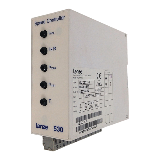
- Page 2 These operating instructions are valid for controllers with the nameplate designation 531__ E 532__ E 533__ E 534__ E Controller type Chassis type Hardware version + index Edition of: 05/1996 revised: 12/2002...
- Page 3 How to use this manual ... To locate information on specific topics, simply refer to the table of contents at the beginning and to the index at the end of this manual. The manual uses a series of different symbols to provide quick reference and to highlight important items.
- Page 4 Safety and application notes for drive controllers (according to: Low Voltage Directive 73/23/EWG) 1. General During operation, drive controllers may have, according to their type of protection, live, bare, in some cases also movable or rotating parts as well as hot surfaces.
- Page 5 4. Erection The devices must erected and cooled according to the regulations of the corresponding documentation. The drive controllers must be protected from inappropriate loads. Particularly during transport and handling, components must not be bent and/or insulation distances must not be modified. Touching of electronic components and contacts must be avoided.
-
Page 6: Table Of Contents
Contents Features of the 530 series of controllers Technical data Controller-specific data Dimensions Scope of supply Application as directed Accessories Installation Installation Connection 4.2.1 Installation corresponding to EMC 4.2.2 CE-typical drive system Connecting voltage Replacing the fuses Connection diagram Setting... -
Page 7: Features Of The 530 Series Of Controllers
Features of the 530 series of controllers The 530 series of controllers series comprises 4 half-controlled single-quadrant controllers with output powers from 0.36 kW to 2 kW for the operation of DC shunt or permanent magnet motors. • Compact single-board controllers for space-saving installation on a mounting plate or DIN rail 35 x 7.5 mm... -
Page 8: Technical Data
Technical data Controller-specific data Controller Output power 1360 2040 Mains frequency f [Hz] 50...60 Mains voltage 190...265 L1, N (100...132 with solder link) Armature current Amax (can be changed for 534) Armature voltage for V = 230 V L1, N Field voltage 0.9 x U L1,⋅N... -
Page 9: Dimensions
Dimensions Type 531 Jumper "BR1", "BR2" (change 230 V / 120 V) Jumper "BR3" (n setting) Type a [mm] b [mm] c [mm] d [mm] Types 532 and 533 Type 534 ∅ ∅ Jumper "BR1", "BR2" (change 230 V / 120 V) Jumper "BR3"... -
Page 10: Scope Of Supply
Scope of supply The scope of supply includes: • the controller 53x_E • the operating instructions • the set-value potentiometer 10 kΩ • plug-in terminals Application as directed • The controllers of the types 53x are electrical equipment for installation into control cabinets of electrical systems or machinery. -
Page 11: Accessories
Accessories Type Armature choke Suitable types depend on motor type − − − Mains choke 2.5 mH, 18 A − − − Type ELN1_0250H018 RFI filter Type EZF1_004A001 EZF1_01812A001 Spring kit for DIN rail 15 mm − − Type EJ00329026 EJ00329061 Knob for pot. - Page 12 Mains choke Mains choke for Weigh type 534 [kg] ELN1_0250H018 2.5...
- Page 13 RFI filter (V = 250 V ±0 %) Design A Design B Types Filter Desi Fixing [Type] 531...53 EZF1_004A001 91.5 63.5 60.4 2 x M4 EZF1_018A001 108 50.8 100 4 x M6...
- Page 14 Armature choke Armature choke [mH] [mm] [mm] [mm] [mm] [mm] [mm] [mm] [mm] [mm] ELK_440H004 ELK_500H002 50/15 2/10 ELA_400H010 40/12 10/18 150 The suitable type of armature choke depends on the motor type.
-
Page 15: Installation
Installation Installation The chassis-type controller is to be installed in a vertical position, with the terminals at the bottom, to ensure sufficient cooling and air circulation. The ambient temperature mut not exceed +45°C. Unwanted voltages fed back from the controllers to the supply mains are reduced by the connection of mains chokes and RFI filters. - Page 16 • The plug connector is suitable for the connection of solid wire or single or multi-strand conductors of cross-sections between 0.14 and 2.5 mm². The length of the free wire should be between 8 and 9 mm. It is not necessary to use ferrules.
- Page 17 The master voltage must be free of mains and ground potential. Several controllers can only be operated from a master voltage when they are electrically isolated. Note for the connection of controller and motor Lenze controller Motor (acc. to DIN 42017 / VDE 0530 part 8) Function Terminal Terminal other...
-
Page 18: Installation Corresponding To Emc
• Lenze has done conformity tests with the controllers of the types 53x in certain, defined drive systems. These tested drive systems are called "CE- typical drive system" in the following. -
Page 19: Ce-Typical Drive System
Control cables Screened signal cable type LIYCY Motor DC motor with separate excitation Lenze series GFQ, GFR or similar Note: Controller, RFI filter, and mains choke are located on one mounting plate. Installation of the CE typical drive system The electromagnetic compatibility of a drive system depends on the type and accuracy of the installation. - Page 20 Grounding • Ground all conductive metal components (controllers, RFI filters, mains chokes) by suitable cables from a central grounding point (PE bar). • Observe the minimum cross-sections prescribed in the safety information. However, for EMC the surface of the contact is important and not the cross- section.
- Page 21 Part of the CE-typical drive system which is located on the mounting plate L1 N Connection mains fuse RFI filter LINE Paint-free bare metal contact surface LOAD Mains choke Paint-free surfaces for screen contact Controller Mounting plate Screened conductive field and connection armature cable with PE...
-
Page 22: Connecting Voltage
Connecting voltage As a standard, the controller is factory-set for the operation on a mains voltage from 190 to 265 V ±0 %. For a mains voltage from 100 to 132 V ±0 % replace jumper "BR1" with "BR2". Caution! This modification must only be carried out by qualified skilled personnel when no voltage is applied. -
Page 23: Replacing The Fuses
Replacing the fuses The fuses protect the controller from non-permissible operating conditions. After the operation of such a protective function, the controller and the system must be checked for further faults before replacing the fuses. For the replacement of the fuses remove the protective cover and disconnect the connectors. -
Page 24: Connection Diagram
Connection diagram Type 531 16 17 = 10...120 V soll Filter R=10 kΩ lin. L1 N 190...265V~ 50 / 60 Hz (100...132 V~ 50 / 60 Hz) see chapter 4.3 "Connecting voltage" standard component Explanations ➀ Coded part ➁ Jumper "BR 3" ➂... - Page 25 Types 532, 533, 534 9 16 17 soll R = 10 k Ω lin. = 10...120 V Filter = 10 V 190...265V~ 50 / 60 Hz (100...132 V~ 50 / 60 Hz) see chapter 4.3 "Connecting voltage" standard component only required for type 534 Explanations ➀...
-
Page 26: Setting
Setting Turn trimmers "I x R", "n ", "n ", "T " and set-value potentiometer fully counterclockwise. Trimmer "I " is factory set to rated controller current. The current range selector for type 534 is factory set to 8 A. Selection of the current range for type 534 The current range of type 534 can be set to 12 A by switching off the controller and moving selector S1 from position 8 A to position 12 A. -
Page 27: Setting The Current Limit
Setting the current limit Setting the current limit is only required if the maximum output current must be reduced. • Turn trimmer "I " fully counterclockwise and "n " fully clockwise. • Connect a moving coil ammeter into the armature circuit to measure the current. - Page 28 After checking and correcting the wiring, commissioning can be started again. • Switch on the mains and close switch "RFR". Turn the set-value potentiometer to maximum or set the master voltage to V = 10 V. Turn trimmer "n " clockwise until the desired maximum motor speed is achieved.
-
Page 29: Operating Modes
Operating modes Switching operation 6.1.1 Controller enable If switch "RFR" is closed, the controller is enabled. If the switch "controller enable" (RFR) is open, the firing pulses are blocked and the controller is reset. 16 17 Note: Only use low-current contacts for the switching of signal cables (20 V / 1 mA) 6.1.2 Controller inhibit The function "RSP", i.e.g the inhibiting of the controller with a normally-open... -
Page 30: Electrodynamic Braking
Electrodynamic braking If the field is excited, the induced armature current is used for braking the motor. Before connecting the brake resistor, the controller is inhibited. The timer relay must be set such that the braking contactor only opens after the motor has stopped. - Page 31 To limit the switching voltage peaks, a zinc oxide varistor (R ) must be connected in parallel to the controller output. For long motor cables (> 50 m) or motors which are connected in parallel, it may be necessary to use an interference suppression module (see chapter 3 "Accessories") Braking circuit: Interference suppression module...
-
Page 32: Reversing
Reversing Reversing is obtained by changing the armature polarity. The motor is electrodynamically braked to standstill. The braking time must be set at the timer relay such that the motor is safely at standstill before the armature is reversed (for dimensioning of the brake resistor see chapter 6.2 "Electrodynamic braking"). -
Page 33: Index
Index Accessories 9 Replacing the fuses 21 Application Reversing 30 as directed 8 Safety information 2 Braking Scope of supply 8 Electrodynamic 28 Setting Select current range 24 Setting the current limit 25 Speed 25 Controller features 5 Controller-specific data 6 Dimensions 7 Armature choke 12 Mains choke 10...
Need help?
Do you have a question about the 530 series and is the answer not in the manual?
Questions and answers