
Subscribe to Our Youtube Channel
Related Manuals for Lenze M MA Series


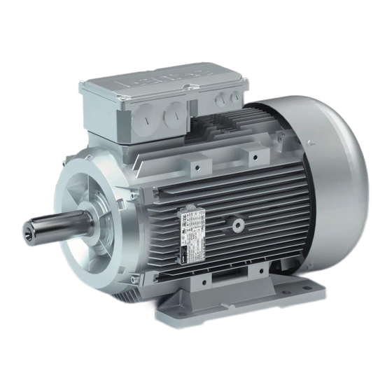
Summary of Contents for Lenze M MA Series
- Page 1 AC motors MLLMA; Basic MLERA...V1 | 0.12 kW ... 45 kW Operating Instructions Three−phase AC motors...
- Page 2 Please read these instructions before you start working! Follow the enclosed safety instructions. Note! For safety−rated built−on accessories, the manufacturer’s operating instructions have to be observed! 0Fig. 0Tab. 0...
-
Page 3: Table Of Contents
......... . . Lenze ¯ BA 33.0005 ¯ 5.0... - Page 4 ..............10.1 Technical data as specified by ordinances (EU) No. 4/2014 and (EC) No. 640/2009 Lenze ¯ BA 33.0005 ¯ 5.0...
-
Page 5: About This Documentation
¯ The documentation must always be in a complete and perfectly readable state. If the information provided in this documentation is not sufficient in your case, please refer to the controller or gearbox documentation. Tip! Information and tools concerning the Lenze products can be found in the download area at www.lenze.com Validity This documentation is valid for three−phase AC motors:... -
Page 6: Conventions Used
Three−phase AC motor (squirrel cage induction motor) in versions according to product key, ^ 14 . Controller Any servo inverter Any frequency inverter Drive system Drive systems including three−phase AC motors and other Lenze drive components Lenze ¯ BA 33.0005 ¯ 5.0... -
Page 7: Notes Used
The operating instructions indicates that the motor housing has threaded holes or through holes. ¯ These holes may not be used to install feet. ¯ Motor mounting is only allowed as fixed installation without feet. Lenze ¯ BA 33.0005 ¯ 5.0... -
Page 8: Safety Instructions
This is vital for safe and trouble−free operation and for achieving the specified product features. ¯ Only qualified skilled personnel are permitted to work with or on Lenze drive and automation components. According to IEC 60364 or CENELEC HD 384, these are persons ... - Page 9 Corrosion protection Lenze offers paints with different resistance characteristics for drive systems. Since the resistance may be reduced when the paint coat is damaged, defects in paint work (e.g. through transport or assembly) must be removed professionally to reach the required corrosion resistance.
-
Page 10: Application As Directed
31 December 2014 may be exclusively used there on a frequency inverter for speed control only. These motors receive the following additional marking. EU REGULATION 640/2009 USE WITH VARIABLE SPEED DRIVE ONLY! Any other use shall be deemed inappropriate! Lenze ¯ BA 33.0005 ¯ 5.0... -
Page 11: Foreseeable Misuse
Align shafts of motor and driving machine exactly to each other. ¯ If deviations from normal operation occur, e.g. increased temperature, noise, vibration, determine the cause and, if necessary, contact the manufacturer. If in doubt, switch off the motor. Lenze ¯ BA 33.0005 ¯ 5.0... -
Page 12: Disposal
Safety instructions Disposal Fire protection ¯ Fire hazard – Prevent contact with flammable substances. Disposal Sort individual parts according to their properties. Dispose of them as specified by the current national regulations. Lenze ¯ BA 33.0005 ¯ 5.0... -
Page 13: Product Description
Product description Identification Product description Identification Three−phase AC motors ... MLLMA Motor with standard output flange Motor with square flange for direct gearbox attachment MT−MDEMA−005.iso/dms MLERA...V1 Basic standard motor MT−MXERA−001.bmp/dms Lenze ¯ BA 33.0005 ¯ 5.0... -
Page 14: Motor Code
Grey iron fan Grey iron fan + 2nd shaft end Grey iron fan + handwheel Size Overall length − Number of pole pairs 2−pole motors 4−pole motors 6−pole motors Design type Internal key Approval cURus Lenze ¯ BA 33.0005 ¯ 5.0... -
Page 15: Encoder Code
For safety function HTL (for incremental encoders) Hiperface (for absolute value encoders) EnDat sin/cos 1 V Safety integration level (SIL) Note! If feedback systems for safety functions are used, the manufacturer’s documentation must be observed! Lenze ¯ BA 33.0005 ¯ 5.0... -
Page 16: Nameplate
14.2 5.10 10.2 10.2 10.3 5.10 16.7 16.8 16.9 cos j (10%) r/min Eff.CL. cos j A D/Y (10%) r/min 16.7 16.4 16.1 16.2 16.3 16.5 16.6 16.6 16.5 16.4 16.1 16.3 16.2 10.1 Lenze ¯ BA 33.0005 ¯ 5.0... - Page 17 Partial load efficiencies for 50Hz operation at a rated power of 50% and 75% CC number Department of Energy (optional) Permissible ambient temperature (e.g. Ta £ 40°C) Standstill current (ampere locked rotor ALR) Plug design (number of poles) Lenze ¯ BA 33.0005 ¯ 5.0...
-
Page 18: Technical Data
As specified by limiting curve A of the pulse voltage from IEC / TS 60034−25:2007 (corresponds to IVIC C/B/B@500V) Noise emission IEC/EN 61800−3 Depending on the controller, see documentation for the controller. Noise immunity Lenze ¯ BA 33.0005 ¯ 5.0... - Page 19 Relative humidity £ 85 %, without condensation Humidity Electrical The motor connection type depends on the controller , inverter instructions Length of the motor cable Length of cable for speed feedback Mechanical IEC/EN60721−3−3 Lenze ¯ BA 33.0005 ¯ 5.0...
-
Page 20: Mechanical Installation
MDERALL100 V1 FT130 MDERALL112 V1 FT130 MDERALL132 V1 FT165 MLLMALN063 FT75 MLLMALN071 FT85 MLLMALN080 FT100 MLLMALN080 FT130 MLLMALN090 FT115 MLLMALN090 FT130 MLLMALN100 FT130 MLLMALN112 FT130 MHERALL080L FT100 MHERALL090L FT115 MHERALL100L FT130 MHERALL112L FT130 MHERALL132L FT165 Lenze ¯ BA 33.0005 ¯ 5.0... -
Page 21: Preparation
To restore the enclosure, re−insert the plugs (screws) after condensate drainage. If the condensation drain holes are not sealed again, the IP enclosure of the motor will be reduced. For horinzontal motor shafts to IP23 and for vertical motor shafts to IP20. Lenze ¯ BA 33.0005 ¯ 5.0... -
Page 22: Installation
Designs with shaft end at the bottom must be protected with a cover at the N−end, preventing the ingress of foreign particles into the fan. Lenze ¯ BA 33.0005 ¯ 5.0... -
Page 23: Assembly Of Built−On Accessories
¯ Only use an extractor for the disassembly. ¯ When using belts for torque/power transmission: – Tension the belts in a controlled manner. – Provide protection against accidental contact! During operation, surface temperatures of up to 140°C are possible. Lenze ¯ BA 33.0005 ¯ 5.0... -
Page 24: Spring−Applied Brakes
±10 %. In case of long motor cables the voltage drop must be checked due to increasing conductor resistance and compensated for by higher input voltage if necessary. The following applies to Lenze system cables: ) 0.08 W U* [V]... -
Page 25: Locking Of The Manual Release
The formula below provides a simplified way to calculate friction energy per switching cycle which must not exceed the limit value for emergency stops that depends on the operating frequency (^ motor catalogue; Lenze drive solutions: formulas, dimensioning, and tables). - Page 26 ¯ Always secure the terminal block against loosening in every position with cheese head screw and nut! Brake not released / operating position Brake released / service position GT−GXX−015.iso/dms GT−GXX−016.iso/dms Cheese head screw with nut Terminal block Manual release lever with knob Fan cover Lenze ¯ BA 33.0005 ¯ 5.0...
-
Page 27: Electrical Installation
¯ The smallest air gaps between uncoated, live parts and against earth must not fall below the following values. Motor diameter Minimum requirements for basic Higher requirements for UL design insulation according to IEC/EN 60664−1 (CE) < 178 mm 6.4 mm 3.87 mm > 178 mm 9.5 mm Lenze ¯ BA 33.0005 ¯ 5.0... -
Page 28: Three−Phase Ac Motor Operation On A Frequency Inverter
Three−phase AC motor operation on a frequency inverter The three−phase AC motors described in these instructions are optimised and qualified for the use on Lenze frequency inverters and can be combined without restrictions. If another inverter is used for operation, the voltage peaks (U... -
Page 29: Screwed Connections On The Terminal Box
Screwed connections on the terminal box Screwed connections on the terminal box Tightening torques [Nm] +/− 10% −−−−− CuZn −−−−− −−−−− [Nm] Material M12x1.5 M16x1.5 M20x1.5 M25x1.5 M32x1.5 M40x1.5 M50x1.5 Plastic Metal Tab. 1 Locking screws and cable glands Lenze ¯ BA 33.0005 ¯ 5.0... -
Page 30: Power Connections On The Terminal Board
Connection to L2 mains rotation, L1 − L2 must be interchanged Connection to L3 mains Separate fan 1~ Terminal board Contact Meaning Note Connection to L1 mains V1 / U2 Connection to N − mains Lenze ¯ BA 33.0005 ¯ 5.0... -
Page 31: Brake Connection To Terminal
Z / data − Zero track inverse / parameter channel − RS485 Shield − housing Shield − incremental encoder The terminal is not assigned if insulation at N−end shield of the motor has been selected! Lenze ¯ BA 33.0005 ¯ 5.0... -
Page 32: Plug Connectors
TCO / PTC / + KTY TB2 / TP2 / R2 TCO / PTC / − KTY BD1 / BA1 Brake + / AC <250 V BD2 / BA2 Brake − / AC <250 V MT−Steckverbinder−001.iso/dms Lenze ¯ BA 33.0005 ¯ 5.0... - Page 33 Single−phase (external view of poles) Contact Name Meaning PE conductor AC fan Not assigned DC fan U− Not assigned Three−phase (external view of poles) Contact Name Meaning PE conductor Not assigned Not assigned MT−Steckverbinder−001.iso/dms Lenze ¯ BA 33.0005 ¯ 5.0...
-
Page 34: Feedback System
Track A / + COS Supply + Mass Zero track inverse / − RS485 Zero track / + RS485 Not assigned Track B inverse / − SIN Shield Encoder housing shield + KTY Thermal detector KTY − KTY Lenze ¯ BA 33.0005 ¯ 5.0... -
Page 35: Terminal Box Han Connectors
Track B Mass Track A MT plug−in connector−001.iso/dms Further information is provided in the system cables system manual at: www.Lenze.de ® Download ® Technical documentation ® Finding technical documentation Filter: Type of contents System manual Filter: Product System cable Terminal box HAN connectors Contact pin HAN−Modular 16 A... - Page 36 Terminal board +KTY / PTC / TCO Thermal sensor −KTY / PTC / TCO Note! Carry out the wiring in *or -in the counter plug: ¯ * − wiring: 6−7−8 ¯ - − wiring: 1−6/2−7/3−8 Lenze ¯ BA 33.0005 ¯ 5.0...
-
Page 37: Commissioning And Operation
Before switch−on, you must ensure that the motor starts with the intended direction of rotation. Lenze motors rotate CW (looking at the driven shaft) if a clockwise three−phase field L1 W U1, L2 WV1, L3 W W1 is applied. Fig. 3 Direction of rotation of the driven shaft Lenze ¯... -
Page 38: Functional Test
¯ Check all functions of the drive after commissioning: ¯ Direction of rotation of the motor – Direction of rotation in the disengaged state (see chapter "Electrical connection"). ¯ Torque behaviour and current consumption ¯ Function of the feedback system Lenze ¯ BA 33.0005 ¯ 5.0... -
Page 39: During Operation
¯ Condition of electrical cables ¯ Speed variations ¯ Impeded heat dissipation – Deposits on the drive system and in the cooling channels – Pollution of the air filter In case of irregularities or faults: (¶ 50). Lenze ¯ BA 33.0005 ¯ 5.0... -
Page 40: Maintenance/Repair
Possible consequence: Property damage and / or personal injury. Protection measure: Repair or replacement of the collateral provider is allowed only by Lenze Service or its empower people. After a service life of 10 years, an inspection of the metal elastomer torque plate is required for the AS1024−8V−K, AS1024−8V−K2;... -
Page 41: Spring−Operated Brakes
¯ After replacing the rotor, the original braking torque will not be reached until the run−in operation of the friction surfaces has been completed. After replacing the rotor, run−in armature plates and counter friction faces have an increased initial rate of wear. Lenze ¯ BA 33.0005 ¯ 5.0... - Page 42 Fatigue failure of the Number of switching Axial load cycle and springs operations of the brake shearing stress on the springs due to radial reversing error of the armature plate Tab. 2 Causes for wear Lenze ¯ BA 33.0005 ¯ 5.0...
-
Page 43: Checking The Component Parts
3. Compare measured rotor thickness with minimally permissible rotor thickness (values ^ 45). 4. If required, exchange the entire rotor. Description ^ 45. Lenze ¯ BA 33.0005 ¯ 5.0... -
Page 44: Checking The Air Gap
3. Tighten screws, torques (¶ 45). 4. Check air gap "s " near the screws using a feeler gauge, "s " (¶ 45). Lrated 5. If the deviation of "s " is too great, repeat the adjustment process. Lrated Lenze ¯ BA 33.0005 ¯ 5.0... -
Page 45: Rotor Replacement
24.6 12.0 16.0 48.0 1.25 0.75 15.5 20.0 48.0 Tab. 3 Characteristics of the spring−applied brake 1) The dimension of the friction lining allows for adjustment of the brake for at least five times. Lenze ¯ BA 33.0005 ¯ 5.0... -
Page 46: Installation Of The Brake
4. Use the screws (10) to mount the stator (7) completely to the end shield (15) (Fig. 5). – Tighten the screws evenly, tightening torque (¶ 45). KL458−012−a Fig. 5 Stator mounting ¬ s Stator Sleeve bolt Lrated Cheese head screw 15 End shield Lenze ¯ BA 33.0005 ¯ 5.0... -
Page 47: Adjusting The Air Gap
Disconnect voltage. The brake must be free of residual torque. − KL458−013−a Fig. 6 Re−adjust air gap Complete stator 10 Cheese head screw Sleeve bolt If the measured value "s " is outside the tolerance of "s ", set the dimension: Lenze ¯ BA 33.0005 ¯ 5.0... -
Page 48: Assembly Of The Friction Plate, Sizes 06 To 16
3. Tighten the cheese head screws (6.1) evenly, (tightening torques (¶ 45). 4. Check the height of the screw heads. The screw heads may not be higher than the minimum rotor thickness. We recommend using screws according to DIN 6912, dimensions (¶ 45. Lenze ¯ BA 33.0005 ¯ 5.0... -
Page 49: Assembly Of The Cover Seal
3. Press the lips of the cover ring into the groove of rotor and flange. – If a friction plate is used, the lip must be pulled over the flanged edge. Repair ¯ We recommend having all repairs carried out by the Lenze customer service. Lenze ¯ BA 33.0005 ¯ 5.0... -
Page 50: Troubleshooting And Fault Elimination
Rated operating mode exceeded (S1 to Adjust rated operating mode to the specified operating conditions. ¯ Externally ventilated or S8 IEC/EN 60034−1) Determination of correct drive by expert or Lenze customer service self−ventilated motors Loose contact in supply cable Tighten loose contact >... - Page 51 Surface temperature > 140°C Overload of the drive Check load and, if necessary, reduce by means of longer ramp−up times Check winding temperature Heat dissipation impeded by deposits Clean surface and cooling fins of the drives Lenze ¯ BA 33.0005 ¯ 5.0...
-
Page 52: Appendix
77.4 82.2 85.4 83.8 86.3 88.2 87.6 For year of manufacture and week of manufacture see nameplate: ^ 16 Lenze Drives GmbH, Breslauer Straße 3, D−32699 Extertal, GERMANY, HR Lemgo B 6478 Motor code MHLMA MHLMA MHLMA MHLMA MHLMA MHLMA... - Page 53 94.5 89.4 90.2 90.8 91.4 91.9 91.9 94.0 93.7 Fertigungsjahr und Fertigungswoche siehe Typenschild: ^ 16 Lenze Drives GmbH, Breslauer Straße 3, D−32699 Extertal, GERMANY, HR Lemgo B 6478 Motor code MHLMA MHLMA MHLMA MHLMA MHLMA MHLMA MHLMA MHLMA LL160−22 LL160−32...
- Page 54 Notes Lenze ¯ BA 33.0005 ¯ 5.0...
- Page 55 Notes Lenze ¯ BA 33.0005 ¯ 5.0...
- Page 56 © 01/2016 | BA 33.0005 | .S]N | 5.0 | TD09 Lenze Drives GmbH Postfach 10 13 52, 31763 Hameln Breslauer Straße 3, 32699 Extertal GERMANY HR Lemgo B 6478 Ü +49 5154 82−0 Ø +49 5154 82−2800 Ù lenze@lenze.com Ú...
Need help?
Do you have a question about the M MA Series and is the answer not in the manual?
Questions and answers