
Related Manuals for Lenze E84AVSC


Summary of Contents for Lenze E84AVSC
- Page 1 L-force Drives EDB84AVSC 13390878 Operating instructions 8400 E84AVSCxxxxx Inverter Drives 8400 StateLine C...
- Page 2 The product catalogue provides information on the possible configuration to order the products. Tip! Current instructions for the contents of the product CD and information and tools for the Lenze products are provided in the download area at http://www.Lenze.com...
-
Page 3: Table Of Contents
......General safety and application notes for Lenze motors ...... - Page 4 8400 StateLine C | Operating instructions Contents Adapting the application individually ..........Function block interconnection of the "Actuating drive speed"...
-
Page 5: About This Documentation
8400 StateLine C controller. The documentation applies to the "simple" "speed-controlled" operation preset by Lenze by default. The most important settings for commissioning will be explained so that many applications using the 8400 StateLine C controller and the preset application "actuating drive speed"... -
Page 6: Safety Instructions
8400 StateLine C | Operating instructions Safety instructions General safety and application notes for Lenze controllers Safety instructions Danger! Sticker with warning note must be displayed prominently and close to the device! Description of the warning signs ... - Page 7 Reduce housing openings and cutouts to a minimum. Lenze controllers may cause a DC current in the PE conductor. If a residual current device (RCD) is used for protection against direct or indirect contact for a controller with three-phase supply, only a residual current device (RCD) of type B is permissible on the supply side of the controller.
-
Page 8: General Safety And Application Notes For Lenze Motors
8400 StateLine C | Operating instructions Safety instructions General safety and application notes for Lenze motors General safety and application notes for Lenze motors (according to Low-Voltage Directive 2006/95/EG) Electrical connection All operations must only be carried out by qualified and skilled... -
Page 9: Residual Hazards
8400 StateLine C | Operating instructions Safety instructions Residual hazards Residual hazards Protection of persons Protection of the machine/plant Before working on the controller, check if no voltage is applied to Drives can reach dangerous overspeeds (e. g. setting of high the power terminals because output frequencies in connection with motors and machines not suitable for this purpose)! The drive controllers do not provide... -
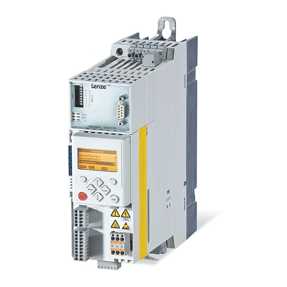
Page 10: Overview Of Terminals
8400 StateLine C | Operating instructions Overview of terminals Overview of terminals Power terminals Power range 0.25 ... 3 kW Power range 3 ... 22 kW (Device sizes 1 ... 3) (Device sizes 4 ... 6) Power range 30 ... 45 kW X80 Terminal strip for drive-based safety "safe torque off (STO)"... - Page 11 8400 StateLine C | Operating instructions Overview of terminals Control terminals X1 CANopen connection S1 CANopen settings (Bus terminating resistor, baud rate and node address) X3 • Analog inputs/outputs • 10 V reference voltage Note: Voltage input A1U and current input A1I must not be used simultaneously! X4 •...
-
Page 12: Connection/Wiring Of The Controller
DI4 Change of direction of rotation DO1 Status "Drive is ready" X101 - relay output COM/NO Status "Error is pending" [4-2] Wiring of the control terminals / preconfigured assignment (Lenze setting) from Firmware V06.00 - DMS 1.1 EN - 11/2011... -
Page 13: Before Commissioning
Commissioning with PC and L-force »EASY Starter« The L-force »EASY Starter« is a Lenze tool for easy online diagnostics, parameter setting and commissioning of the controller. Commissioning with PC and L-force »Engineer«... - Page 14 L-force »EASY Starter« and L-force »Engineer StateLevel« are provided free of charge in the internet. Current software can be found in the download area under http://www.Lenze.com. For communication between PC and controller, the USB diagnostic adapter can be used for instance (see the following accessories overview).
-
Page 15: General Notes On Parameters
Moreover, each code has a name and specific attributes, as for example access type (reading, writing), data type, limit values and default setting ("Lenze setting"). For the sake of clarity, some codes contain "subcodes" for saving parameters. This Manual uses a slash "/"... - Page 16 Control elements Execute the function assigned to the function key (see LCD display) Execute the stop function set in C00469 (Lenze setting: Inhibit controller) Deactivate stop function again (Lenze setting: Enable controller again) In the menu level: Select menu/submenu ...
- Page 17 Go To Param – Use the function key to return to the SAVE main menu. Load Lenze setting 2. Use the / navigation keys to select the C00002/001 parameter to be set within a submenu. Off / Finished 3.
- Page 18 8400 StateLine C | Operating instructions Before commissioning General notes on parameters Multilingualism All texts displayed in the keypad are in English. From version 11.00.00 onwards, the most important menus as well as diagnostic and configuration parameters can are also available in German and French. To set a different language, select the Language selection menu item in the main menu of the keypad.
-
Page 19: Change Parameter Settings With Pc And Lenze Software
General notes on parameters 5.2.2 Change parameter settings with PC and Lenze software The USB diagnostic adapter, for instance, can be used for the communication between the PC (including the L-force »EASY Starter« or L-force »Engineer« software) and the controller, see illustration. -
Page 20: Save Parameter Settings In The Memory Module Safe Against Mains Failure
General information In the delivery state, the Lenze setting of the parameters has been saved to the integrated memory module. When the device or the external 24 V voltage supply is switched on, all parameters are automatically loaded from the memory module into the main memory of the controller. -
Page 21: User Menu For Quick Access To Frequently Used Parameters
The user menu of a device contains a selection of frequently used parameters to be able to access and change these parameters quickly. Parameter Name Lenze setting C00051 Display of actual speed value C00053 Display of DC-bus voltage... -
Page 22: General Notes On Applications
8400 StateLine C | Operating instructions Before commissioning General notes on applications General notes on applications The technology applications integrated in the drive controller provide the main signal flow for the implementation of a general or a special drive solution. Technology application "Actuating drive speed"... -
Page 23: Select Control Mode
C00007 Control mode Selection list Info (Lenze setting printed in bold) 0 Wiring has changed This display appears if the FB interconnection has been changed in the preconfigured I/O interconnection. 10 Terminals 0 The technology application is controlled via the digital and analog input terminals of the controller. - Page 24 Comparison of the control modes "Terminals 0/2/11/16" The following table shows which functions of the preset application "actuating drive speed" have been preconfigured in the prevailing control mode for a control via terminals (Lenze setting printed in bold): Control mode "terminals"... Function of the application Info "actuating drive speed"...
-
Page 25: Frequently Used Device Commands
C00002/1 Load Lenze setting This device command serves to reset all parameter settings in the device to the Lenze setting in order to keep a defined device configuration. Note: All parameter changes which have been carried out after the last time the parameter set was saved will be lost! •... -
Page 26: Check Software Version (Firmware Version)
Note: After the reset (acknowledgement) of the current error, further errors may be pending which must also be reset. • The current error is displayed in C00170. Selection list Info (Lenze setting printed in bold) 0 Off / ready 1 On / start Reset (acknowledge) current error C00002/21... -
Page 27: Commissioning
8400 StateLine C | Operating instructions Commissioning Drive behaviour by default (Lenze setting) Commissioning Drive behaviour by default (Lenze setting) Preset motor control "V/f characteristic control (VFCplus)" The 8400 StateLine controller supports various processes for motor control. By default, the V/f characteristic control (VFCplus) with linear characteristic for asynchronous motors is preset in C00006 as motor control. -
Page 28: Quick Commissioning With The Keypad
4. Load Lenze setting to controller. This step is recommended to get a defined device configuration. All parameter settings in the controller are reset to the Lenze setting. from Firmware V06.00 - DMS 1.1 EN - 11/2011... - Page 29 Use the function key to accept the 1 On / Start 4 Action cancelled selection and to leave the editing mode. CINH Now the Lenze setting is being loaded and then the controller will be restarted. from Firmware V06.00 - DMS 1.1 EN - 11/2011...
- Page 30 V/f base frequency: If the rated motor voltage differs from the mains voltage, the V/f base frequency has to be adapted. Based on the restart of the controller after Actual speed loading the Lenze setting: C00051 Press the function key to change to the 0 rpm main menu.
- Page 31 Note! If the controller is enabled at mains power-up. the controller remains in the "ReadyToSwitchOn" status when being in the Lenze setting (the green LED "DRIVE READY" flashes twice approx. every 1.25 seconds). To be able to change to the "SwitchedOn" status, the controller enable must be deactivated first: set terminal X4/RFR to LOW level.
- Page 32 Select speed setpoint In case of terminal control in the preset control mode "Terminals 0": In the Lenze setting, the main speed setpoint is selected via the analog terminal X3/A1U (e.g. via a setpoint potentiometer). – Scaling: 10 V ≡ 100 % reference speed (C00011) ≡ 1500 rpm...
- Page 33 8400 StateLine C | Operating instructions Commissioning Quick commissioning with the keypad Other control functions ...in the preset control mode "Terminals 0" or with keypad control: Terminal control Keypad control Function C00727/2 HIGH Manual DC-injection braking • Manual DC-injection braking allows the drive to be quickly braked to a standstill without the need to use an external brake resistor.
-
Page 34: Adapting The Most Important Parameters To The Drive Task
100.00 % C00142 Auto-start option 0x19 ≡ Controller inhibit when • the controller is switched on (device on) • Undervoltage • Loading of the Lenze setting C00173 Mains voltage 0: "3ph 400V / 1ph 230V" C00034/1 AIN1: Configuration 0: "-10...+10 v"... -
Page 35: Basic Settings
8400 StateLine C | Operating instructions Commissioning Adapting the most important parameters to the drive task 6.3.1 Basic settings Parameter Name Lenze setting C00011 Appl.: Reference speed 1500 rpm C00059 Appl.: Reference frequency C11 C00015 VFC: V/f base frequency 50.0 Hz... - Page 36 Operating threshold for the "OC6: Motor overload (I²xt)" error message • If the calculated motor load reaches the operating threshold set here, the "Warning" error response is carried out in the Lenze setting. The error response can be set in C00606. Setting range Lenze setting (min.
- Page 37 Adapting the most important parameters to the drive task C00142 Auto-start option Starting performance of the controller after mains connection, undervoltage, loading of the Lenze setting as well as a reset of "Trouble" or "Fault" can be parameterised individually. Setting range Lenze setting (min.
-
Page 38: Application Parameters
Application parameters In the following, the signal flow of the "actuating drive speed" application is shown according to the Lenze setting. For a better readability, non-effective functions are not shown in this representation. A representation with all interfaces/parameters can be found in the appendix. - Page 39 Configuration of the analog input for current or voltage measurement Selection list Info (Lenze setting printed in bold) 0 -10...+10 V Input signal is the voltage signal -10 V ... +10 V • -10 V ... +10 V ≡ -100 % ... +100 % 1 0...20 mA...
- Page 40 Acceleration time of the ramp generator for the main speed setpoint • Time period for the acceleration from standstill to reference speed set in C00011. Setting range Lenze setting (min. value | unit | max. value) 0.000 999.999 2.000 s...
- Page 41 Adapting the most important parameters to the drive task C00114 Digital inputs (DIx): Polarity The polarity of each digital input of the device can be inverted via this bit field. Setting range Lenze setting (min. hex value | max. hex value) 0x0000 0xFFFF 0x0000 Decimal: 0 The keypad displays the setting as bit string (bit 0 is at Binary: 00000000.00000000...
-
Page 42: Motor Control Parameters
• A detailed description of this and other motor control types not mentioned here (e.g. vector control) can be found in the software manual and in the »Engineer« online help for the controller. Selection list Info (Lenze setting printed in bold) 6 VFCplus: V/f linear Linear V/f characteristic • For drives a constant, speed-independent load torque. - Page 43 • When a variable switching frequency is selected, the switching frequency may change as a function of the load and rotational frequency. Selection list (Lenze setting printed in bold) 1 4 kHz var./drive-optimised 15 2 kHz constant/min. Pv 2 8 kHz var./drive-optimised 16 4 kHz constant/min.
- Page 44 Adapting the most important parameters to the drive task C00910/1 Max. pos. output frequency Max. positive output frequency for all motor control modes Setting range Lenze setting (min. value | unit | max. value) 1000 1000 Hz C00910/2 Max. neg. output frequency Max.
-
Page 45: Diagnostics & Troubleshooting
8400 StateLine C | Operating instructions Diagnostics & troubleshooting LED status displays for device status Diagnostics & troubleshooting LED status displays for device status The control of the two LEDs "DRV-RDY" and "DRV-ERR" in the lower part on the front of the controller depends on the device status. For the meaning please refer to the following table: DRV-RDY DRV-ERR Description... -
Page 46: Diagnostics Using The »Easy Starter
8400 StateLine C | Operating instructions Diagnostics & troubleshooting Diagnostics using the »EASY Starter« Diagnostics using the »EASY Starter« When an online connection has been established to the controller, the most important information on the current operation, device status and operating time is indicated clearly in the »EASY Starter«... -
Page 47: Diagnostic/Display Parameters
8400 StateLine C | Operating instructions Diagnostics & troubleshooting Diagnostic/Display parameters Diagnostic/Display parameters Diagnostic/display parameters serve to display device-internal process factors, current actual values, and status messages, e.g. for diagnostic purposes. In the keypad, these parameters can be found in the Diagnostics menu: Par1 8400 StateLine C Par1 8400 StateLine C Actual speed... -
Page 48: Monitoring
8400 StateLine C | Operating instructions Diagnostics & troubleshooting Monitoring Monitoring The controller is provided with various monitoring functions which protect the drive against impermissible operating conditions. If a monitoring function responds, an entry will be made into the logbook of the controller, ... -
Page 49: Error Messages
• Eliminate error cause and reset (acknowledge) error manually afterwards. dF14: SW/HW invalid Device error Consultation with Lenze required. dF18: BU RCOM error dF21: BU Watchdog dF22: CU watchdog dF25: CU RCOM error Mains switching too frequent. • After switching the mains 3 times in one minute, there must be a switching •... - Page 50 • This cancels the identification process. • Do not execute any device function The Lenze setting of the motor data is which may activate controller inhibit. used. ID4: Resistor identification error The device has recognised that an error...
- Page 51 • Use motor filters, cable lengths, and • Mostly, incorrectly executed motor cable types recommended by Lenze. connections are the cause. • If motor filters with additional • If motor filter, motor cable length, and terminals for +UG and –UG and devices...
- Page 52 8400 StateLine C | Operating instructions Diagnostics & troubleshooting Error messages Error message Cause Remedies OC15: Cross current controller limitation Cross current controller limitation is • Observe load requirements. active. • Correct dimensioning or reduce setpoint generation dynamics if necessary. •...
- Page 53 PS07: Par. mem. module invalid The parameter set saved to the memory Consultation with Lenze required. module is invalid. PS08: Par. device invalid The parameter set in the device is invalid. PS09: Par. format invalid The code format is invalid.
-
Page 54: Maloperation Of The Drive
8400 StateLine C | Operating instructions Diagnostics & troubleshooting Maloperation of the drive Maloperation of the drive Motor does not rotate Cause Remedy DC-bus voltage is too low Check mains voltage • Red LED is blinking every 1 s • Display in the keypad: LU Controller is inhibited Deactivate controller inhibit •... - Page 55 8400 StateLine C | Operating instructions Diagnostics & troubleshooting Maloperation of the drive Motor consumes too much current Cause Remedy boost has been selected too high Correct setting with C00016 V/f base frequency has been selected too low Correct setting with C00015 Rated motor data (stator resistance, speed, current, Execute automatic motor parameter identification with frequency, voltage) and cos ϕ...
-
Page 56: Adapting The Application Individually
8400 StateLine C | Operating instructions Adapting the application individually Adapting the application individually This chapter describes further adaptation options of the application based on the respective function block interconnection. Further functions that are first deactivated by default (e.g. ramp smoothing for the main speed setpoint, speed limit values and speed blocking zones) can be activated in the main signal flow through parameter setting. -
Page 57: Function Block Interconnection Of The "Actuating Drive Speed" Application
8400 StateLine C | Operating instructions Adapting the application individually Function block interconnection of the "Actuating drive speed" application Function block interconnection of the "Actuating drive speed" application Every drive solution for the 8400 device series is implemented in the form of a "function block interconnection"... -
Page 59: Activating Additional Functions In The Signal Flow
Resp. to open circuit AIN1 Response to open circuit at the analog input when being configured as 4 ... 20 mA current loop. Lenze setting: "TroubleQuickStop". The drive is braked to standstill within the deceleration time parameterised for quick stop independently of the defined setpoint and can be kept there. -
Page 60: Speed Limit Values
Activating additional functions in the signal flow 8.2.1 Speed limit values C00635 L_NSet_1: nMaxLimit Maximum speed setpoint for speed setpoint limitation Setting range Lenze setting (min. value | unit | max. value) -199.99 199.99 199.99 % C00636 L_NSet_1: nMinLimit Minimum speed setpoint for speed setpoint limitation... -
Page 61: Speed Blocking Zones
• Selection of the maximum limit values for the blocking zones in which the speed must not be constant. Setting range (min. value | unit | max. value) 0.00 199.99 Subcodes Lenze setting Info C00632/1 0.00 % L_NSet_1: Blocking speed 1 max C00632/2 0.00 %... -
Page 62: Ramp Smoothing
Ramp smoothing C00134 Ramp smoothing main setpoint Configuration of the ramp smoothing for the main setpoint Selection list Info (Lenze setting printed in bold) 0 Off Ramp rounding deactivated 1 PT1 behaviour Ramp rounding with PT1 behaviour C00182 S-ramp time PT1 PT1 S-ramp time for the main setpoint ramp function generator •... -
Page 63: Implementing More Additional Functions In The Signal Flow
8400 StateLine C | Operating instructions Adapting the application individually Implementing more additional functions in the signal flow Implementing more additional functions in the signal flow The pre-assignment of the application can be reconfigured via configuration parameters. Thus, additional functions can be implemented in the signal flow as well. Please observe the "source/destination principle"... -
Page 64: Pre-Assignment Of The Input And Output Interfaces
8400 StateLine C | Operating instructions Adapting the application individually Implementing more additional functions in the signal flow 8.3.1 Pre-assignment of the input and output interfaces In the preset control mode "terminals 0", the input and output terminals of the "actuating drive speed"... - Page 65 8400 StateLine C | Operating instructions Adapting the application individually Implementing more additional functions in the signal flow Brief description of the input and output interfaces For a detailed interface description see the software manual. Input interface Function Output interface Function nMainSetValue_a Main speed setpoint...
-
Page 66: Motor Potentiometer
Alternatively, the main speed setpoint can be generated via a motor potentiometer function. In the Lenze setting, the motor potentiometer function is deactivated. Activation is possible via C00806 or the bMPotEnable process input. The behaviour of the motor potentiometer during switch-on of the device can be selected in C00805. - Page 67 Signal flow For a quick implementation of the motor potentiometer function, the "Terminals 11" control mode is available in C00007. In this control mode, the digital inputs DI3 and DI4 are linked with the control inputs "increase speed" and "reduce speed" of the motor potentiometer function:...
- Page 68 Adapting the application individually Implementing more additional functions in the signal flow Parameter Parameter Name Info/Lenze setting C00806 Use of motor potentiometer 0 The motor potentiometer is not used. • The analog value applied to the nIn_a input is looped through without any changes to the nOut_a output.
-
Page 69: Process Controller
– Integral action component can be switched off – Comparison function "Actual value = setpoint" In the Lenze setting, the process controller is deactivated. The process controller is activated by selecting the operating mode in C00242. Configuration parameters serve to link the inputs of the process controller to the required process signals. - Page 70 Switch off the I component of the process controller • In conjunction with the operating mode set in C00242 (Lenze setting: "Off"). TRUE I-component of the process controller is switched off. nPIDVpAdapt_a Adaptation of gain Vp set in C00222 in percent •...
- Page 71 Signal flow The following signal flow shows an example configuration where the analog input is used for defining the actual speed or sensor value (actual process value). In this case, the main speed setpoint is selected via fixed setpoints (C00039/1...3).
- Page 72 8400 StateLine C | Operating instructions Adapting the application individually Implementing more additional functions in the signal flow Parameter Parameter Name Info/Lenze setting C00242 Operating mode - process controller Selection of the operating mode of the PID process controller Basic signal flow...
-
Page 73: Parameter Change-Over
8400 StateLine C | Operating instructions Adapting the application individually Implementing more additional functions in the signal flow 8.3.4 Parameter change-over For up to 32 freely selectable parameters, the basic function "parameter change-over" provides a change-over between four sets with different parameter values. ... - Page 74 8400 StateLine C | Operating instructions Adapting the application individually Implementing more additional functions in the signal flow Configuring the list by means of parameterisation The parameter list is combined similarly to the user menu via parameter setting. The following application example shows the required procedure for configuring the list without using the »Engineer«...
-
Page 75: Index
8400 StateLine C | Operating instructions Index Index C243 C244 Accel. time - main setpoint (C00012) C247 Accessories for commissioning C26/1 Analog input (AIN1) C2611/x Characteristic (C00010/x) Configuration (C00034/1) C27/1 Gain (C00027/1) Offset (C00026/1) C34/1 Analog voltage output (O1U) Gain (C00434/1) C39/1...3 Offset (C00435/1) C434/1... - Page 76 Operating mode (C00242) Root function (C00233) Tn (C00223) Vp (C00222) Language of keypad L-force »EASY Starter« L-force »Engineer« Load Lenze setting (C00002/1) Main setpoint Acceleration time Deceleration time Ramp smoothing Mains voltage (C00173) Max. neg. output frequency (C00910/2) Max. pos. output frequency (C00910/1)
- Page 77 8400 StateLine C | Operating instructions Index from Firmware V06.00 - DMS 1.1 EN - 11/2011...
- Page 78 © 11/2011 Lenze Drives GmbH Service Lenze Service GmbH Breslauer Straße 3 Breslauer Straße 3 D-32699 Extertal D-32699 Extertal Germany Germany +49 (0) 51 54 / 82-0 00 80 00 / 24 4 68 77 (24 h helpline) +49 (0) 51 54 / 82-11 12 Lenze@Lenze.de...
Need help?
Do you have a question about the E84AVSC and is the answer not in the manual?
Questions and answers