
Related Manuals for Philips M3001A


Summary of Contents for Philips M3001A
- Page 1 S E R V I C E G U I D E M3/M4 Monitors (M3046A) Measurement Server (M3001A and M3000A) Measurement Server Extensions (M3015A and M3016A) P A T I E N T M O N I T O R I N G...
-
Page 2: Sixth Edition
Printed in Germany 03/05 Sixth Edition *M3046-9300F* Part Number M3046-9300F 4512 610 07711... -
Page 3: Seventh Edition
M3046A M2/M3/M4 Monitors M3000A/M3001A Measurement Servers M3015A/M3016A Extensions to the Measurement Servers Service Guide M3046-9300F Reordering Number: 4512 610 07711 Printed in Germany. March 2005 Seventh Edition... - Page 4 Philips Medical Systems shall not be liable for errors contained herein or for incidental or consequential damages in connection with the furnishing, performance, or use of this material.
- Page 5 Printing History New editions of this document will incorporate all material updated since the previous edition. Update packages may be issued between editions and contain replacement and additional pages to be merged by a revision date at the bottom of the page. Note that pages which are rearranged due to changes on a previous page are not considered revised.
- Page 6 • the instrument is used in accordance with the instructions for use. To ensure safety, use only those Philips parts and accessories specified for use with the Monitor. If non-Philips parts are used, Philips Medical Systems is not liable for any damage...
- Page 7 Philips’s patient monitoring systems, this book is designed for you. If you are new to Philips’s product line or monitoring systems, you may find this book helpful as an orientation to the equipment. If you have already worked on the systems and now want further details on how they work, you are likely to find much of the information you need here.
-
Page 9: Table Of Contents
Section 2 - Measurement Server Description and Features ......19 M3001A Measurement Server Standard Package ......19 M3001A Measurement Server Extended Measurements Packages . - Page 10 M3000A Measurement Server Standard Package ......20 M3000A #C06 Measurement Server Extended Measurements Package ... . 20 Features .
- Page 11 Sidestream CO Features ..........49 Block Diagram of the Sidestream CO measurement .
- Page 12 Installation of Wireless Infrastructure ......... . 78 Configuring the Radio Frequency of the M3/M4 Monitor .
- Page 13 M3000A / M3001A ........
- Page 14 Invasive Pressure Performance Test ........156 Performance Test .
- Page 15 Warnings, Cautions and Safety Precautions ........220 General Reassembly/Refitting Comments .
- Page 16 M3001A Part Numbers - Front Bezel ........
-
Page 17: Introduction To The Instrument
Introduction to the Instrument Objectives In order to meet this chapter’s goals, you should become familiar with the Monitor, Measurement Server and the Measurement Server Extensions, and be able to identify their component parts in some detail. As well, you should be able to explain how the Measurement Server and Measurement Server Extensions acquire and process physiological measurements and how the Monitor displays the data. -
Page 18: Introducing The Instrument Components
(M80xxA) and M3/M4 (M3046A, Revision E) monitors. The M3012A’s Pressure/ Temperature channel works in the same way as that of the M3001A, with which the M3012A shares all specifications, as documented in the M3/M4 Instructions for Use, except for the weight, which is 450g (0.99lb). - Page 19 The signals are converted into digital data, and processed before being communicated to the Monitor. The server device is referred to as the Measurement Server or simply the Server in this manual. All versions of the M3000A and M3001A Measurement Servers are covered by this manual.
-
Page 20: Instrument Components
Instrument Components Instrument Components The Monitor, the Measurement Server, and Measurement Server Extensions are shown in the following diagram: Measurement Server (M3000A and M3001A) M3000A has a gray bezel. M3001A has a white bezel. Measurement Server Extensions M3016A M3015A Monitor (M3046A) Functional descriptions of these components are to be found later in this chapter. -
Page 21: A Quick Description Of The Monitor
A Quick Description of the Monitor A Quick Description of the Monitor Front Panel Keys Alarm Alarm Suspend Setup Indicator Key & Indicator Main Screen Alarm Silence/Reset Key Silence Main Reset Suspend Setup Screen On Off/Standby AC Power Off/Standby Battery Battery LED Green - Battery full (>95%) -
Page 22: Back Of Monitor
A Quick Description of the Monitor Back of Monitor: Locking Mechanism for the Measurement Server Connector to the Measurement Catches for Server (≤48V) attaching the Measurement Server LAN/Software Update Connector (≤5V) Mounting Plate Connector for an additional display (VGA Interface) (≤3.3V) Protective earth Nurse Call Relay connector point... -
Page 23: A Quick Description Of The Measurement Server
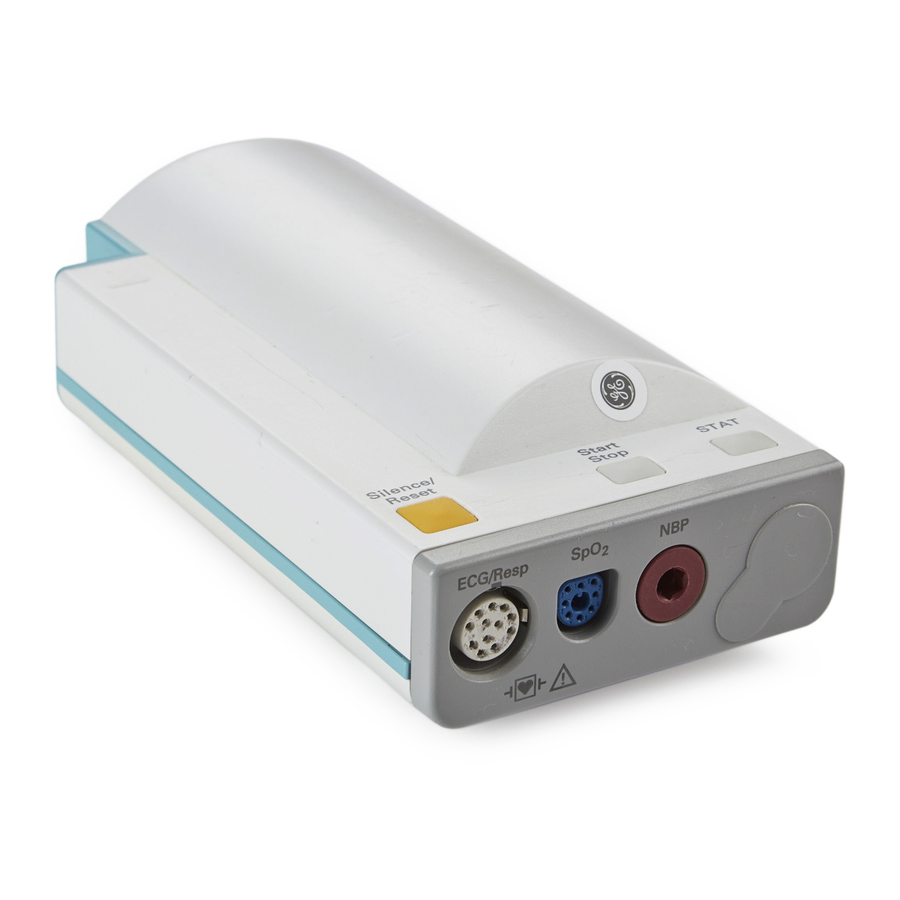
A Quick Description of the Measurement Server A Quick Description of the Measurement Server Overview of the Measurement Server Measurement Connectors for the M3000A #C06, M3001A #C06 and #C18 Measurement Servers Note: Press and Temp cannot be used at the sam e time. - Page 24 MSL cable connector to the monitor. connector - connect either invasive pressure transducer or temperature probe (M3000A #C06; M3001A #C06 and #C18 only). Press and temp cannot be used at the same time. You might have a version of the Measurement Server that does not have this connector.
-
Page 25: A Quick Description Of The Measurement Server Extension
A Quick Description of the Measurement Server Extension A Quick Description of the Measurement Server Extension Overview of the Measurement Server Extensions M3015A & M3016A Catches for attaching the Measurement Server Connectors to Monitor & Measurement Server Measurement Connectors Measurement Connectors for the M3015A Measurement Server Extension Press Note:... -
Page 26: Measurement Connectors For The M3016A Measurement Server Extension
A Quick Description of the Main Screen Measurement Connectors for the M3016A Measurement Server Extension Press Note: Press and Temp cannot Temp be used at the same time on the same Extension. MAINSTREAM CO (Option #A01 only) A Quick Description of the Main Screen QuickSet Time Monitor Label... -
Page 27: Theories Of Operation And Functional Descriptions
Monitor Description • M3046A Monitor Theory of Operation • Functional Description of the Monitor Hardware Section 2 M3001A/M3000A Measurement Server Description and Features • Measurement Server Theory of Operation • Functional Description of the Measurement Server Hardware • Electrocardiogram/Respiration (ECG/Resp) Measurement •... -
Page 28: Monitor Theory Of Operation
LAN connector to a central print server. The Monitor can communicate with an Philips Information Center via the LAN Connector (wired network) or via the Wireless LAN Assembly (wireless network) when the appropriate options are present. -
Page 29: Display And User Interface Software Module
Monitor Theory of Operation Display and User Interface Software Module The Display and User Interface Software displays measurement data and status information on the color LCD display, and processes the operator inputs from the HIF Controller. The interface consists of the following sub-modules: •... -
Page 30: Printer Manager
Monitor Theory of Operation Printer Manager The printer manager formats and prints the following reports on either a locally attached printer or a remote printer connected to the Instrument via the M3 Print Server: • Tabular Trend Report—The printer manager takes raw data from the trend module and generates a formatted report. -
Page 31: Irda/Serial Communication Manager
Monitor Theory of Operation IrDA/Serial Communication Manager The IrDA/Serial Communication manager is responsible for sending raw data to the local recorder (serial protocol) or printer (in a format that complies with the IrDA (Infrared Data Association) standard). The IrDA/Serial Communication manager provides a general printer or recorder device interface to the printer or recorder manager, and maps the general printer/ recorder services to the device protocol. -
Page 32: Functional Description Of The Monitor Hardware
Functional Description of the Monitor Hardware Functional Description of the Monitor Hardware The Monitor receives data from the Measurement Server and Measurement Server Extension via the Server-to-Monitor link bar and presents this data on the color LCD display. The following block diagram shows the main functional areas. Alarm Relay VGA (Network) -
Page 33: Display Video Controller
Functional Description of the Monitor Hardware The main functional areas are summarized in the following: • System Board—Comprising a 68360 Controller, the Memory System, the Video System, LAN (network) connector link to Server, ECG-Out, Human Interface and DC/DC Converter. • Connector Board—Connecting the System Board to the AC Power Supply and battery. The LAN (network) filter and connector, the VGA connector and the Alarm Relay Output (Nurse Call) are located on the Connector Board. -
Page 34: Human Interface Controller
Functional Description of the Monitor Hardware Human Interface Controller The Human Interface Controller (HIF) is the interface between the operator and the Monitor itself. It monitors the operator controls and the Battery Controller, formats the data, and routes it to the Display & Operator Controls Manager from which it receives commands and status also. -
Page 35: Infrared (Irda) Interface
GSI Lumonics XE-50p Chart Recorder-specific protocol. Wireless LAN Interface The Wireless LAN interface provides a wireless connection to the Philips LAN. The Wireless LAN CPU connects to the wired LAN inside the Monitor and provides the software drivers for the RF Board. -
Page 36: M3001A Measurement Server Extended Measurements Packages
Section 2 - Measurement Server Description and Features M3001A Measurement Server Extended Measurements Packages All versions of the M3001A Measurement Server offer EASI lead placement using an EASI 5-electrode cable set. The conventional 12-lead ECG capability of M3001A #C12 and #C18 only works with the IntelliVue family of monitors. -
Page 37: Measurement Server Theory Of Operation
Measurement Server Theory of Operation • Transfer data between Monitors. The M3001A supports data transfer to and from the Intel- liVue family of patient monitors. Settings Transfer The Measurement Server can be transported from one Monitor to another and still keep its measurement settings. -
Page 38: Functional Description Of The Measurement Server Hardware
Functional Description of the Measurement Server Hardware Heart rate software. • • The Third Layer—This consists of the interface management and interface controllers. This layer contains the date/time, and Server-to-Monitor link managers. • The Fourth Layer—This consists of the monitoring algorithms and software to acquire the physiological signals. -
Page 39: Electrocardiogram/Respiration (Ecg/Resp) Measurement
You can use either standard or EASI lead placements with the M3046A Release E together with the M3001A. Using a standard 5-electrode set in EASI lead placement you can monitor three out of 12 standard ECG leads simultaneously and continuously at the bedside. EASI- derived 12-lead ECGs and their measurements are approximations to conventional 12-lead ECGs. -
Page 40: Ecg/Resp Features
Electrocardiogram/Respiration (ECG/Resp) Measurement ECG/Resp Features This illustration shows the user controls and connectors for the ECG/Resp. This standard 12-pin connector will accept either a 3-lead or a 5-lead ECG cable. Features of the ECG/Resp measurements are described in the following paragraphs. ECG Modes The QRS complexes are detected automatically. -
Page 41: Block Diagram Of The Ecg/Resp
Electrocardiogram/Respiration (ECG/Resp) Measurement Safety To ensure the safety of the patient, the patient-applied parts are isolated from ground by optical isolators and a transformer. The circuit is also encapsulated in plastic. Block Diagram of the ECG/Resp Input Protection ROM/RAM Network ASIC To/From System CPU... - Page 42 Electrocardiogram/Respiration (ECG/Resp) Measurement from the CPU) controls the analog-to-digital conversion and reads out the digitized ECG data. The CPU communicates with the ECG ASIC via a built-in serial link. To prevent interference from the 50/60Hz power line, the common mode signal is used to drive the right leg (RL) drive amplifier.
- Page 43 Electrocardiogram/Respiration (ECG/Resp) Measurement A respiration wave, • Pace pulse data, • INOP messages, and • status messages. • The ECG/Resp CPU receives control messages from the system CPU. ECG Software on the System CPU Display Filter ECG Wave & Scaling Heart Rate Cardiotach HR Limit...
- Page 44 Electrocardiogram/Respiration (ECG/Resp) Measurement • ECG Alarming This software receives the averaged heart rate from the cardiotach software and derives alarms by comparing this rate against the limits and the asystole condition. Heart rate alarms are communicated to the display unit via the operating system. •...
-
Page 45: Non-Invasive Blood Pressure (Nbp) Measurement
Non-invasive Blood Pressure (NBP) Measurement Non-invasive Blood Pressure (NBP) Measurement Description The Measurement Server has a non-invasive blood pressure measurement for the Monitor monitoring device. It is designed to be used with adult, paediatric, or neonatal patients, in ICU and OR environments. Measurements The measurement produces numerics for the systolic, diastolic, and mean blood pressure values. - Page 46 Non-invasive Blood Pressure (NBP) Measurement NBP Modes The measurement offers adult, pediatric, and neonatal modes. The following table lists the cuff inflation limits for each mode: Subsequent Inflations, Mode First Inflation Stat Mode Above Systolic Pressure Adult Pediatric Neonatal The following table lists the measurement ranges for each mode: Mode Systolic Diastolic...
-
Page 47: Block Diagram For Nbp
Non-invasive Blood Pressure (NBP) Measurement Block Diagram for NBP Components The following components carry out the major signal processing functions within the Introduction to the Instrument... -
Page 48: Nbp Measurement Characteristic
Non-invasive Blood Pressure (NBP) Measurement measurement. Pressure Pump—Inflates the cuff to preset limits, once or repeatedly, depending on the measurement method used. Pressure Sensor—Measures cuff pressure using solid-state technology. Overpressure Safety System—Triggers alerts at given pressures and time limits, and deflates the cuff. -
Page 49: Arterial Oxygen Saturation And Pleth (Spo 2 /Pleth) Measurement
Arterial Oxygen Saturation and Pleth (SpO /PLETH) Measurement Arterial Oxygen Saturation and Pleth (SpO /PLETH) Measurement Description The Measurement Server has a pulse, arterial oxygen saturation, and plethysmogram measurement. Measurements The measurement produces numerics for the arterial oxygen saturation value and the pulse rate, along with a real-time wave for the plethysmogram. -
Page 50: Block Diagram Of The Spo 2 /Pleth Circuit
Arterial Oxygen Saturation and Pleth (SpO /PLETH) Measurement This illustration contains an example of a typical wave in SpO Pleth Block Diagram of the SpO /PLETH Circuit Self-Test Signal Generator Clipping Detector Digital photo Variable Photo Signal Bandpass ROM/RAM Gain Amplifier current Processor... - Page 51 Arterial Oxygen Saturation and Pleth (SpO /PLETH) Measurement Bandpass The bandpass stage contains a bandpass filter for the modulated signals coming in from the photo-amplifier. This filters out noise outside a passband centred on the modulation frequency. Variable Gain This section amplifies the incoming signals. The gain is set by a digital to analog converter (DAC) which allows 512 gain settings.
- Page 52 Arterial Oxygen Saturation and Pleth (SpO /PLETH) Measurement Algorithm Software on the System CPU Pleth, Wave Average Value Algorithm Calculation Pulse Rate Alarms Alarming Control Controls The SpO Algorithm receives the demodulated and filtered red and infrared signals, and the transducer coding information from the SpO measurement frontend.
-
Page 53: Temperature And Invasive Blood Pressure (Temp/Press) Measurement
Temperature and Invasive Blood Pressure (Temp/Press) measurement Temperature and Invasive Blood Pressure (Temp/Press) measurement Description The Measurement Server has a measurement channel which can measure invasive pressure or temperature. Measurements The measurement produces a numeric for temperature; or a real-time pressure wave, together with the pulse rate and numeric readings for the systolic, diastolic, and mean blood pressure values. -
Page 54: Block Diagram
Temperature and Invasive Blood Pressure (Temp/Press) measurement Temp Mode Measurement Range: -1 to 45 C (30 to 113 Safety To ensure the safety of the patient, the patient-applied part is isolated from ground by opto- couplers and a transformer. The circuit is also encapsulated in plastic. Block Diagram This illustration shows the block diagram of the Temp/Press circuit. -
Page 55: Temperature And Invasive Pressure Software
Temperature and Invasive Blood Pressure (Temp/Press) measurement Transducer Detection The transducer being used can be determined by recognising the coding in the connector. This is done by the transducer detection circuitry. A window comparator checks the input voltages provided by the transducer against specified limits. Current Source The current source generates a constant current for the resistor array that is used to measure the temperature. -
Page 56: Block Diagram Of The Temp/Press Software
Temperature and Invasive Blood Pressure (Temp/Press) measurement • System CPU communication • ADC controller and data acquisition • Wave/numeric processing and filtering • Pressure/temperature mode detection Block Diagram of the Temp/Press Software Pressure / Temperature Mode Detector Wave Processing System &... -
Page 57: Invasive Pressure Software Module
Temperature and Invasive Blood Pressure (Temp/Press) measurement available. This forces the CPU to retrieve the data and to calculate the scaled pressure waveform of temperature value. Wave Processing and Filtering Pressure measurement: Data from the A/D converter is sent to a single-pole digital filter which generates the specified frequency response. -
Page 58: Temperature Software Module
Temperature and Invasive Blood Pressure (Temp/Press) measurement Acquisition Control This component receives the hardware-related information from the signal acquisition component. This includes status data and error/failure reports. Wave Processing The raw waveform from the Signal Acquisition module is filtered. Gain and offset values of the raw waveform are corrected so that the wave sample-values represent absolute values according to the selected scale. - Page 59 Temperature and Invasive Blood Pressure (Temp/Press) measurement Block diagram of the Temperature Software Module Pressure Waveform Average Temp. Value Calculation Temperature Temp. Alarms Alarming Temperature Temp. User Contro Controls Signal Acquisition This module is responsible for the A/D conversion of the analog signal from the temperature transducer.
-
Page 60: Section 3 - Measurement Server Extensions Description And Features
Section 3 - Measurement Server Extensions Description and Features Section 3 - Measurement Server Extensions Description and Features The Measurement Server Extensions (M3015A and M3016A) are flexible patient measurement units which partner with the Measurement Server to form the base for a variety of systems that enable easy customization to a hospital’s requirements. -
Page 61: M3015A Measurement Server Extension Theory Of Operation
M3015A Measurement Server Extension Theory of Operation Settings Transfer The combination of the Measurement Server and the Measurement Server Extension can be transported from one Monitor to another and still keep its measurement settings. The settings (such as alarm limits) are stored in the Measurement Server. This behaviour permits fast and easy transport Alarms Reset The Measurement Server Extension responds to the Silence/Reset key on the Measurement... -
Page 62: Functional Description Of The M3015A Measurement Server Extension Hardware
Functional Description of the M3015A Measurement Server Extension Hardware Functional Description of the M3015A Measurement Server Extension Hardware The Extension receives information signals (such as Temp/Press) and a sidestream CO sample from the patient then transmits the data through the Server to the Monitor via the Server-to-Monitor link bar. -
Page 63: Hardware Block Diagram
Functional Description of the M3015A Measurement Server Extension Hardware Hardware Block Diagram 36 - 60 Volt SRL Connector Power Sync to Measurement Server RxD/TxD FEL Addresses (MSL connector) Microstream CO BOARD Gas Inlet Gas Outlet Pressure or PRESS/ +15V 36-60V Temperature TEMP Transducer... -
Page 64: Sidestream Co 2 Measurement
Monitor monitoring device. It is designed to be used with the M3000A/ M3001A Measurement Server for adult, pediatric, or neonatal patients, in a hospital environment and during patient transport in and outside hospitals by clinical users. The patients can be intubated or non-intubated. -
Page 65: Sidestream Co 2 Features
Sidestream CO Measurement Sidestream CO Features This illustration shows the user controls on the Server and the connector for appropriate tubing for the sidestream CO measurement on the Extension. Connector for sidestream CO tubing. Sidestream CO Wave The two calibration marks are located at 10% and 60% of wave channel height. The lower calibration mark is labelled 0 mmHg (0.0 kPa) on all scales. - Page 66 Sidestream CO Measurement O correction is required only on M3015A Measurement Server Extensions with CO Data Acquisition hardware revision A.01.09 or lower. • N O Correction—This can be turned on or off. If N O correction is off, only oxygen cor- rection to CO is made.
-
Page 67: Block Diagram Of The Sidestream Co Measurement
Sidestream CO Measurement Block Diagram of the Sidestream CO measurement to/from Server Serial Controller interface with Peripherals Analog Pressure Section Sensor Exciter Exciter Gas Outlet Flow System Detectors Pump, Source Source solenoid, Temp Sensor Gas Inlet tubing with Sample Line Inlet Optical Code Recog-... - Page 68 Sidestream CO Measurement Detectors The detectors are used to detect the reference signal (the signal which comes directly from the IR source) and the main signal (the signal which passes through the sample cell). Pressure Sensor The pressure sensor is used to measure the ambient pressure during the auto zero process and to measure the pressure in the measurement cell during measurement mode.
-
Page 69: M3016A Measurement Server Extension Theory Of Operation
M3016A Measurement Server Extension Theory of Operation M3016A Measurement Server Extension Theory of Operation The application-specific software for the second pressure/temp and CO runs on the main CPU in the Measurement Server (see “Measurement Server Theory of Operation” on page 21). The pressure/temperature and the CO frontends communicate the pre-processed physiological data via the Frontend Link Protocol to the application-specific software on the main CPU of the Measurement Server. -
Page 70: Functional Description Of The M3016A Measurement Server Extension Hardware
Functional Description of the M3016A Measurement Server Extension Hardware Functional Description of the M3016A Measurement Server Extension Hardware The Extension receives information signals (such as Temp/Press and mainstream CO ) from the patient then transmits the data through the Server to the Monitor via the Server-to- Monitor link bar. -
Page 71: Hardware Block Diagram
Functional Description of the M3016A Measurement Server Extension Hardware Hardware Block Diagram 36 - 60 Volt SRL Connector Power Sync to Measurement Server RxD/TxD FEL Addresses (MSL connector) Opto-coupler Mainstream CO Transducer and Power Transformer Floating/Non-floating isolation Pressure or PRESS/ 36-60V Temperature TEMP... -
Page 72: Mainstream Co 2 Measurement
Mainstream CO Measurement Mainstream CO Measurement Description The M3016A Measurement Server Extension has a mainstream carbon dioxide respiratory gas measurement for the Monitor monitoring device. It is designed to be used with the M3000A Measurement Server for adult, pediatric, or neonatal patients, in a hospital environment and during patient transport in and outside hospitals by clinical users. -
Page 73: Mainstream Co 2 Features
Mainstream CO Measurement Mainstream CO Features This illustration shows the user controls on the Server and the connector for the mainstream measurement transducer on the Extension. The parts are described in the paragraphs following the illustration: Connector for a mainstream CO transducer. - Page 74 Mainstream CO Measurement • O Correction— There is a fixed correction of 45% O • Humidity Correction—This correction is selectable between Body Temperature Pressure Saturated (BTPS) and Standard Pressure Temperature Dry (STPD). The Extension meas- ures BTPS and uses this correction formula: STPD BTPS .
-
Page 75: Block Diagram Of The Mainstream Co 2 Measurement
Mainstream CO Measurement Block Diagram of the Mainstream CO measurement Introduction to the Instrument... -
Page 76: Theory Of Operation For The M3016A Mainstream Co 2
Mainstream CO Measurement Theory of Operation for the M3016A Mainstream CO The signals progress through the circuit as follows: Microprocessor This is in overall control of the mainstream CO measurement functions. As well, it performs the following functions: • Serial communication, via optocouplers. •... -
Page 77: Tutorial For The Introduction To The Instrument
Tutorial for the Introduction to the Instrument Tutorial for the Introduction to the Instrument Question 1: Which is the complete list of what the Measurement Server measure? a. The Multi-Measurement Server acquires the physiological signals ECG, respiration, invasive and non-invasive blood pressure, oxygen saturation of the blood, and temperature. -
Page 78: Answers To The Tutorial For The Introduction To The Instrument
Answers to the Tutorial for the Introduction to the Instrument Answers to the Tutorial for the Introduction to the Instrument 1) a. (See page 2 for more details.) 2) b. (See page 15 for more details.) 3) c. (See page 21 for more details.) Introduction to the Instrument... -
Page 79: Installing The Instrument
The appropriate installation procedures are described in this chapter. Concepts The following section contains information that you need to understand before attempting an installation of an M3046A Monitor, an M3000A/M3001A Measurement Server and, where present, M3015A/M3016A Measurement Server Extensions. Instrument... -
Page 80: Safety
Safety Safety Patient Safety To better secure patient safety, become familiar with the details of the “Monitor and Measurement Server Specifications” chapter of the Instructions for Use. Patient Leakage Current The patient leakage current is less than 10µA at 230V/50Hz. The equipment has floating inputs (Type CF) that are protected against the effects of defibrillation and electrosurgery. -
Page 81: Equipotential Grounding
Preparing to Install the Monitor WARNING Disconnect the Monitor from the AC source by unplugging the power cable from the AC source receptacle or from the AC power connector at the side of the Monitor. The On-Off/Standby button does not disconnect the Monitor from the AC mains supply. WARNING Do not operate the M3046A Monitor on a 2-wire AC supply Connect the grounding wire to the equipotential grounding post on the Monitor:... -
Page 82: Environment
Preparing to Install the Monitor Apart from the possible danger caused by leakage currents, no other hazards are known to result from the simultaneous use of the Monitor with other patient-connected equipment. Environment To ensure a completely safe electrical installation, follow the instructions described later in “Installing the Monitor”. -
Page 83: Explanation Of Symbols Used
Preparing to Install the Monitor Explanation of symbols used: Standby for switching the Monitor on and off. Attention, consult accompanying documents. Infra-red Connector for connection to a printer. On the Measurement Server - Defib Data In, that is the ECG marker pulse sent from the defibrillator to the Monitor. - Page 84 The printer port uses LED devices for infrared communication with the printer. These LED devices are measured to be AEL Class 1 LED Products per IEC 825-1 and CENELEC EN60825-1 Standards. The Philips M3046A Compact Portable Patient Monitor complies with the 0366 requirements of the Council Directive 93/42/EEC of 14 June 1993...
- Page 85 Preparing to Install the Monitor The following are the markings on the back of the M3001A Measurement Server and the Measurement Server Extension: Prod No. M30XXA SN: XXXXXXXXXX Opt: XXX XXX XXXXXX M30XXA D-71034 Boeblingen Germany Shows date of manufacture...
-
Page 86: Unpacking The Monitor
In addition you should receive all of the options and accessories that you have ordered. If anything is missing, contact your Philips Medical Systems representative immediately. If anything has been damaged in transit, keep the packing material for inspection and contact your Philips Medical Systems representative immediately. -
Page 87: Connecting The Measurement Server
Connecting the Measurement Server... Switch the Monitor on using the On-Off/Standby button: Silence Main Suspend Setup Reset Screen On-Off/Standby AC Power Off/Standby Battery Making the Altitude Setting A correct altitude setting is important to ensure accurate CO readings. Step 1 Enter Config Mode and press the Setup key. - Page 88 Connecting the Measurement Server... c. Turn the latch guard to lie perpendicular across the edge of the latch. Step 2 Place the Measurement Server on the back of the Monitor. If it is not tight against the back of the Monitor, slip it away from the link bar until it Step 3 Slip the Measurement Server forward until it clicks into place.
-
Page 89: With The Measurement Server Separate From The Monitor
Connecting the Measurement Server..with the Measurement Server Separate from the Monitor You can connect the Measurement Server to the Monitor using a server link cable (MSL) as follows: Step 1 You can connect the cable to the plug on the link bar, or directly to the Monitor as follows: Latch Link Bar... -
Page 90: Tension
An M3015A/M3016A Measurement Server Extension must be used with a M3000A/ M3001A Measurement Server. The Extension does not function alone. Attach the Measurement Server to the Measurement Server Extension by sliding it into the grooves on the Measurement Server Extension and clicking it into place. -
Page 91: Attaching The Measurement Server To A Mount
Attaching the Measurement Server to a Mount Attaching the Measurement Server to a Mount Step 1 Make sure the Measurement Server is oriented correctly relative to the mount (see the picture below). Step 2 Place the Measurement Server on the back mount. If it is not tight against the mount, slip it in the direction of the measurement connectors until it is. -
Page 92: Connecting To The Nurse Call Relay
Modification for Nurse Call Alarm Relays Some customers may want to have an Open-On-Alarm relay instead of a Closed-On-Alarm for their Nurse Call system. Qualified Philips service personnel can modify the connector board, part number M3046-66522. The modification should be done only on request, in the field. All factory supplied connector boards or monitors have the original board including the Close-On-Alarm Relay. - Page 93 Modification for Nurse Call Alarm Relays Step 1 Cut the existing conductor path on the upper side of the connector board with a sharp implement: 1. Cut connector path 2. Remove Shavings Step 2 Very carefully remove all copper or plastic shavings from the board. Step 3 Turn board over.
-
Page 94: Verification Procedure
Installation of Wireless Infrastructure Verification Procedure Perform the following tests. Step 1 Power on test (see page 142) Step 2 Nursecall Performance test (see page 157) Step 3 Safety test (see page 159) NOTE You must document the modification for a particular unit, including the verification tests, in the CSO. - Page 95 Installation of Wireless Infrastructure The following cable is required to interconnect the configuring PC to the Wireless LAN adapter in the M3/M4 patient monitor: • 9-pin D female - 1/8 in. male stereo phono cable (PN M1360-61675) Copying the Configuration Tools to the Configuring PC The first step in the procedure is to copy the configuration tool software from the IntelliVue Information Center Application Software CD ROM to the configuring PC.
- Page 96 Installation of Wireless Infrastructure Making the Config Files Writeable The Config Files are read-only and must be made writeable for the tool to be used for configuration. The following steps describe the procedure after the files have been copied to the configuring computer: Open the ConfigFiles directory by clicking on the ConfigFiles folder in the tools Step 1...
- Page 97 Installation of Wireless Infrastructure Step 4 Click on Properties to display the selected file’s Properties window. Click in the Attributes: box preceding Read-only to remove the check. This removes Read-only from the selected file. If the configuration tool is run with this file set as Read-only, the following error message NOTE will be displayed.
- Page 98 Installation of Wireless Infrastructure c. click Browse to access the Browse application d. select ConfigTool in the tools menu of the stored configuration tools files e. locate the file ConfigTool.exe in the ConfigTool directory f. double click ConfigTool.exe to enter it into the Open: field of the Run window.
- Page 99 Installation of Wireless Infrastructure Step 10 Unsnap the gray cover on the upper right side of the M3/M4 Monitor housing to expose the female stereo phono plug on the Wireless Adapter, as shown in the next figure: Stereo Phono Plug Step 11 Connect the phono plug end of the 9-Pin D female - 1/8 in.
- Page 100 Installation of Wireless Infrastructure Step 14 Click OK to open the Wireless Bedside Parameters window: Step 15 Modify the “domain” field according to your design requirements. Refer to Appendix A of the M3185A IntelliVue Clinical Network Service Manual for the appropriate wireless configuration worksheets.
- Page 101 Installation of Wireless Infrastructure Step 16 Create a log file of the Wireless Bedside configuration. NOTE The log file is a.txt file that contains the menu dialog of the most recent configuration. Near the end of this file is a summary of the device’s configuration settings. This file may be viewed in Notepad or printed for later reference.
- Page 102 Installation of Wireless Infrastructure If the Read-only attribute has not been removed from the configuration tool files, the following error message will be displayed. Click OK to exit the tool and remove the Read-only attribute following the procedure • described in Making the Config Files Writeable. If the serial cable connecting the configuring PC to the device or the PC’s COM port is inaccessible or not working, one of the following windows will be displayed: For Wireless Adapter...
-
Page 103: Connecting To The Ecg Output Or Marker Input
Connecting to the ECG Output or Marker Input Connecting to the ECG Output or Marker Input See the specifications for the ECG Output and for the Marker Input under Interfaces in the Monitor Performance Specifications section of the Specifications chapter of the Instructions for Use, and the documentation for the device you are connecting. - Page 104 Configuring the Monitor Step 4 Select Reference. Step 5 Select Auscult. or Invasive. For versions of the M3046A Monitor with software revision D or lower, do the following. In service mode: Step 1 Select 'Setup NBP' Step 2 Select 'Cal Mode' Step 3 Select desired NBP measurement characteristic according to the table and graphs below:...
- Page 105 Configuring the Monitor Figure 1 Systolic readings of NBP Measurement Characteristics for M3 Release B and M3 Release C compared to readings obtained using the manual auscultatory method (Korotkoff) and direct arterial measurement. Figure 2 Diastolic readings of NBP Measurement Characteristics for M3 Release B and M3 Release C compared to readings obtained using the manual auscultatory method (Korotkoff) and direct arterial measurement.
-
Page 106: Installing An Additional Display
Installing an Additional Display Installing an Additional Display An additional display must be installed by an Philips Medical Systems service engineer or authorized Service Representative. By the addition of a display, the M3/M4 Monitor becomes a system and must be safety-tested as such after installation. The required tests are described in “Testing the Instrument”... - Page 107 Installing an Additional Display Action Required Following Earth Outside Leakage Current Measurement Medically- Patient Vicinity Medically- (See Table above) Used Room Used Room Result 1 Result 2 Result 3 Additional protective Separation No action earth OR device required separation required Here the patient monitor is device connected to a non-medical device...
-
Page 108: Safety Specification
Installing an Additional Display Where separation transformer is required, the power cable connection to the display must be secured so that the transformer cannot be disconnected by hand. Where an additional protective earth is required, the grounding cable must be screwed to the protective earth connector on the rear of the Monitor (see the illustration below under “Installation”... -
Page 109: Installing The 12V Adapter
Installing the 12V Adapter Installing the 12V Adapter The 12V adapter (option number M3080A #C32) is used with a vehicle 12V supply to power an M3/M4 Monitor. The Adapter must be connected to ground or to the vehicle chassis. Detailed instructions can be found in the Instruction sheet delivered with the Adapter (M3080-9011A). -
Page 110: Installing The Wireless Infrared Printer Connector (M3080A #H05)
Installing the Wireless Infrared Printer Connector (M3080A #H05) Local To enable a local printer. Remote To enable a printer connected through the network. Remote To enable a printer connected through the network. Remote To enable a printer connected through the network. a. -
Page 111: Connecting A Local Printer
Connecting a Local Printer Step 1 Attach the support tray to the front, right corner of the table mount. The plastic support tray push-fits over the lip of the table mount. Make sure the dove-tail slot on the tray engages with the table mount correctly. Step 2 Remove the adhesive protection strip from the support tray and attach one half of the velcro fixing onto it. -
Page 112: Connecting A Remote Printer
WARNING The Monitor must be connected to the dedicated M3 network only. The special network cables supplied by Philips Medical Systems for this purpose must be used (see the IntelliVue Clinical Network Service Manual for details). Connecting a Local Recorder You can connect a standalone strip chart recorder (option M3080 #H20, GSI Lumonics XE- 50p) to your monitor via the serial recorder interface, available as option M3046A #J16. -
Page 113: Site Preparation Guidelines
Site Preparation Guidelines Order the Roll Stand (M3080A Option #A30) or the Wall Mount (M3080A Option #A31) for a dedicated mounting solution for your recorder. See “Mounting Options for the Local Recorder” on page 111. The following recordings are supported: •... -
Page 114: Mounting Solutions
Mounting Solutions The mounting solutions described in this manual are subject to change. For the latest information, please visit the Patient Monitoring section of the Philips Medical Systems website, and follow the links to mounting solutions. For detailed mounting instructions, refer to the documents supplied with the mounting hardware. -
Page 115: Installing The Universal Bed Hanger (M3080A #A11)
Installing the Universal Bed Hanger (M3080A #A11) Installing the Universal Bed Hanger (M3080A #A11) The hanging mount is used for hanging the Monitor on the bed footboard/headboard or a rail. It is delivered ready-to-use and does not require installing. Slider Step 1 Unpack the Bed Hanger and check all parts are available. -
Page 116: Warnings, Cautions, And Safety Precautions Relating To Wall Mount Installation
Warnings, Cautions, and Safety Precautions Relating to Wall Mount Installation Warnings, Cautions, and Safety Precautions Relating to Wall Mount Installation • Make sure that you have read all applicable instructions before attempting to install the wall mount. • Wall mounts that are intended to support monitors must be capable of supporting four times the weight of the Monitor when properly installed. -
Page 117: Installing The Wall Rail (M3080A #A13)
Installing the Wall Rail (M3080A #A13) Installing the Wall Rail (M3080A #A13) The wall rail is intended for use with the Universal Bed Hanger (#A11). To mount the rail securely, you need 3 screws. These are not provided because the type of surface dictates the type of screw used. -
Page 118: Screwed Directly To A Wall
Installing the Tilt/Swivel Mount (M3080A #A14) Screwed Directly to a Wall This option is used to mount the Monitor on a wall but to also provide tilt and swivel capability. To mount the assembly securely, you need 3 screws. These are not provided because the type of surface dictates the type of screw used. -
Page 119: Mounted To The Gcx Wall Channel (M3080A #A15)
Installing the Tilt/Swivel Mount (M3080A #A14) Mounted to the GCX Wall Channel (M3080A #A15) This option is used to mount the Monitor to a GCX Wall Channel but to also provide tilt and swivel capability. Rail Step 1 Unpack the Tilt/Swivel mount and check all parts are available. Step 2 Make sure the wall channel end-stop has been fitted. -
Page 120: Attached To A Universal Pole Clamp
Installing the Tilt/Swivel Mount (M3080A #A14) Attached to a Universal Pole Clamp This option is used to attach the Tilt/Swivel mount to a Universal Pole clamp. The Monitor can then be mounted on a pole or rail and can provide tilt and swivel capability. Rail Step 1 Unpack the Tilt/Swivel mount and check all parts are available. -
Page 121: Attached To The Monitor
Installing the Tilt/Swivel Mount (M3080A #A14) Attached to the Monitor This option is used to attach the Tilt/Swivel mount directly to the rear of the Monitor. The Monitor can then be mounted on the GCX Wall Channel or can be used together with the Universal Pole Clamp. -
Page 122: Installing The Gcx Wall Channel (M3080A #A15)
Installing the GCX Wall Channel (M3080A #A15) Installing the GCX Wall Channel (M3080A #A15) This option is the GCX Wall Channel only. To install it, follow the documentation packaged with the channel. Installing the Instrument... -
Page 123: Installing The Universal Pole Clamp (M3080A #C05)
Installing the Universal Pole Clamp (M3080A #C05) Installing the Universal Pole Clamp (M3080A #C05) This option is used to mount the Monitor on a pole or rail. Step 1 Unpack the clamp and check all parts are available. Step 2 Decide whether the clamp is to be secured for vertical positioning (on a pole) or for horizontal positioning (on a rail). -
Page 124: Installing The Measurement Server Mounting Options
Installing the Measurement Server Mounting Options Installing the Measurement Server Mounting Options To allow the Measurement Server to be mounted remotely from the Monitor, special mounting plates are available. One plate can be used to mount the Server to a wall or other fixture. - Page 125 Installing the Measurement Server Mounting Options Step 3 Place the cable (1) on the clamp (2), as illustrated.Use the visual guide (3) and the positioning notch (4) to ensure you have the cable correctly positioned. Step 4 Squeeze open the side clips (5) and ease the cable into the clamp so that the clips grip the gray mouldings (6).
- Page 126 Installing the Measurement Server Mounting Options Step 6 Select two screws and suitable fixings appropriate to surface the material. If necessary, mark the screw positions on the surface and drill suitable holes. Step 7 Insert the 2 screws through the screw holes provided in the plate. Step 8 Tighten the screws.
-
Page 127: Server Mounting Plate (M3080A #A02)
Mounting Options for the Local Recorder Server Mounting Plate (M3080A #A02) This option is used for mounting the Server on a rail or pole. The rotatable clamp gives 4 fixed positions. It is delivered ready-to-use and does not require installing. Latch Lever Step 1... -
Page 128: Msl Cable Termination
MSL Cable Termination MSL Cable Termination The following installation procedure describes how to install the wall installation cable kit when the patient monitor and the measurement server are not located at the same site. The kit consists of two connector boxes and a cable (15m or 25m). For this procedure you need the Insertion Tool (M3086-43801) and a small screwdriver. - Page 129 MSL Cable Termination Step 3 Use the Insertion Tool (M3086-43801) to position each wire on the PCB according the following wiring schematic, where each color corresponds to a number. NOTE The Insertion Tool should be set to cutting mode = on. The Insertion Tool automatically removes the insulation at the connection site, clamps the wire in the correct position, and cuts off the excess wire.
- Page 130 MSL Cable Termination Step 5 Slide the PCB back on to the metallic mounting flange. Step 6 Use screws to fasten the mounting flange to the wall. NOTE US version only: Fasten the rectangular wall-mounting plate to the wall. Attach the mounting flange to the wall-mounting plate.
-
Page 131: Disposing Of The Monitor, Measurement Server And Measurement Server Extensions
Disposing of the Monitor, Measurement Server and Measurement Server Extensions Disposing of the Monitor, Measurement Server and Measurement Server Extensions WARNING To avoid contaminating or infecting personnel, the service environment or other equipment, make sure the equipment has been appropriately disinfected and decontaminated before disposal. -
Page 132: Tutorial For Installing The Instrument
Tutorial for Installing the Instrument Tutorial for Installing the Instrument Question 1: For patient safety, where and how should monitoring equipment be mounted? a. Do not mount any portion of monitoring equipment over a patient’s bed. b. Lead expansion bolts are neither adequate nor safe to use when mounting equipment on plaster board walls. -
Page 133: Answers To The Tutorial For Installing The Instrument
Answers to the Tutorial for Installing the Instrument Answers to the Tutorial for Installing the Instrument 1) b. (See page 100 for more details.) 2) e. (See entire chapter for more details.) 3) b. (See page 65 for more details.) Installing the Instrument... - Page 134 Answers to the Tutorial for Installing the Instrument Installing the Instrument...
-
Page 135: Maintaining The Instrument
Maintaining the Instrument Objectives In order to meet this chapter’s objectives, you should be able to perform light maintenance and preventive maintenance for the Monitor, the Measurement Server and, where present, the Measurement Server Extension through the following tasks: • Inspection of the Instrument. •... -
Page 136: Recommendations For Maintenance Frequency
• Cleaning procedures. • Clean as needed. • Testing Procedures • See "Testing the Instrument". Preventive Maintenance for the M3000A/ M3001A Measurement Server • Cleaning procedures. • Clean as needed. • Non-invasive Blood Pressure Cali- • Once every two years. -
Page 137: Maintenance Checklist
Page Inspecting the Instrument Inspect Cables, Cords and Housing Preventive Maintenance Tasks Replacing the Backlight Tube Assembly M3000A/M3001A NBP Calibration and Perform- ance tests M3015A • Replacement of the Pump and CO2 Scrubber (units with serial number prefix DE020xxxxx only) •... -
Page 138: Inspecting The Instrument
Verify that the backlight tube brightness is adequate. Replace the backlight tube if necessary. NOTE Philips recommends replacement of the backlight tube at the latest after 20 000 hours (approximately 3 years) of use. Inspect Cables and Cords Step 1 Examine the line/power plug for damage. -
Page 139: Preventive Maintenance Tasks
The intensity of the fluorescent tube used for backlight illumination of the LCD Display gradually decreases over time. As a result, periodic replacement is necessary. Philips recommends replacement of the Backlight Tube Assembly after 3 years (20 000 hours) of continuous use or if there is noticeable decrease in the display illumination. -
Page 140: M3015A
Preventive Maintenance Tasks M3015A NOTE 1. Allow 5 seconds between individual service procedures in order to ensure stable equipment conditions. 2. When certain Monitor procedures are running (for example, AutoZero or purging), service procedures are not possible and trying to start them will result in a message “Service Operation Failed”... -
Page 141: Replacement Of The Pump And Co 2 Scrubber
The effectiveness of the Pump and the CO Scrubber gradually decreases over time. As a result, periodic replacement is necessary. Philips recommends replacement as follows: • After 15,000 hours of use (check “Pump Op Time”. See “Checking and Resetting Time Counters” on page 153). -
Page 142: Cleaning Agents
(e.g. blood, mucus) present on the surface to be cleaned and disinfected. Philips makes no claims regarding the efficacy of these chemicals or this method as means for infection control. Consult your hospital’s Infection Control Officer or Epidemiologist. -
Page 143: Battery Handling, Maintenance And Good Practices
(M8043A) to maintain and condition your batteries. • Battery disposal - Batteries should be disposed of in an environmentally-responsible man- ner (see also page 115). Consult the hospital administrator or your local Philips representa- tive for local arrangements. Do not dispose of the battery in normal waste containers. - Page 144 Battery Handling, Maintenance and Good Practices The AC Power LED is only on when the power cord is connected and AC power is available to the Monitor. In this case, the battery can be either charging or fully charged. The battery LED can be green, yellow, or red depending on the following conditions: AC power standby switch on or off...
-
Page 145: Charging The Battery
Battery Handling, Maintenance and Good Practices Charging the Battery Battery charging should be done in stable temperature conditions within the range 0... 35 in order to ensure correct and full loading of the battery. Battery status is displayed by the battery gauge in the bottom right corner of the resting display. -
Page 146: Conditioning A Battery
Battery Handling, Maintenance and Good Practices Conditioning a Battery What is Battery Conditioning? Battery conditioning recalibrates the battery to ensure that it has accurate information on the actual battery capacity. Why is Battery Conditioning Necessary? The capacity of a battery decreases gradually over the lifetime of a battery. Each time a battery is charged its capacity decreases slightly. - Page 147 Battery Handling, Maintenance and Good Practices Conditioning a Battery Using the Battery Charger and Conditioner (M8043A) We recommend you use the Battery Charger and Conditioner (M8043A) for all your battery maintenance needs. The M8043A analyses the battery status, and then charges and/or conditions the battery automatically as required, with no input from the user necessary.
-
Page 148: Accessing The Battery Status Window
Battery Handling, Maintenance and Good Practices Turn on the monitor, and leave it on until it switches off automatically. Turn the monitor off using the On/Off/Standby switch. Reconnect the monitor to the AC power supply. Charge the battery until it is full (the battery LED on the monitor is green). Repeat steps 2 to 6. - Page 149 Battery Handling, Maintenance and Good Practices When the Time-to-Full shows 0, the battery-charge LED on the front panel remains lit until battery calibration is complete. Maintaining the Instrument...
-
Page 150: Battery Inop Messages
Battery Handling, Maintenance and Good Practices Battery INOP Messages The following battery-related INOP messages are issued by the Monitor. All INOPs continue until the Monitor is plugged into the AC power or the INOP condition is fixed. BATTERY LOW—This is a hard INOP which indicates that the remaining battery-operating time is less than approximately 20 minutes. -
Page 151: Tutorial For Maintaining The Instrument
Tutorial for Maintaining the Instrument Tutorial for Maintaining the Instrument Question 1: What is battery conditioning and how often must it be performed? a. Conditioning a battery refers to the complete discharge of a charged battery by allowing it to die out while in non-critical use. The empty battery may then be recharged and put back into use. -
Page 152: Answers To The Tutorial For Maintaining The Instrument
Answers to the Tutorial for Maintaining the Instrument Answers to the Tutorial for Maintaining the Instrument 1) c. (See pages 119 and 127 for more details.) 2) d. (See page 122 for more details.) 3) a.(See pages 125 and 126 for more details.) Maintaining the Instrument... -
Page 153: Testing The Instrument
Instrument measurement results are accurate. When authorized Philips personnel service the Instrument, they report these results back to Philips. The collected data forms a database to be used in product development. These specific tests are required for the NBP parameter and for the sidestream CO parameter. -
Page 154: Test Reporting
Test Reporting Test Reporting The following table shows what must be recorded on the Service Record after completing the tests in this chapter. Test What to record Visual V:P or V:F Power On PO:P or PO:F P NIBP PN:P/X1/X2/X3/X4 or PN:F/X1/X2/X3/X4 P CO PCO2:P/X1/X2/X3/X4/X5/X6/X7/X8 or... -
Page 155: Recommendations For Test Frequency
Recommendations for Test Frequency Recommendations for Test Frequency The testing checklist appears in the next section of this chapter. The listed procedures should be performed as indicated in the Suggested Testing Timetable below. The checklist may be photocopied and should be completed by the tester. It should be filed for future reference. Suggested Testing Timetable Frequency Functionality Assurance... -
Page 156: Test Map
Test Map Test Map The test map shows which tests are required in which situations. Service Event Test Blocks Required (When performing...) ..Complete these tests) Installation of M3/M4 with no display Perform Visual and Power On test connected to the VGA output blocks Installation of M3/M4 with a display Perform Visual, Power On and... -
Page 157: Testing Checklist
Testing Checklist Testing Checklist Check Topics in this Chapter Here Page Functionality Assurance Tests Performance Assurance Test Quick System Check System Self-Test Preventive Maintenance Tests NBP Accuracy, Leakage, Linearity and Valve Test Sidestream CO2 Performance Test Accuracy and Performance Procedures Temperature Accuracy ECG/Resp Performance Invasive Pressure Performance Test... -
Page 158: Serial Numbers
Serial Numbers Serial Numbers When recording test results, these are always associated with a particular instrument by means of the serial number. The serial numbers for the Monitor and the Measurement Server can be seen in the “Revisions” window (press Setup key then select “Revisions”). However, if a Measurement Server Extension (M3015A or M3016A) is in use, the number will not appear and must be noted down from the back of the Extension. -
Page 159: Functionality Assurance Tests
Functionality Assurance Tests PO:P or PO:F where P=pass, i.e. the monitor boots up displaying no error codes and displays an ECG wave and F=fail Functionality Assurance Tests The following functionality assurance checks are recommended to verify proper operation daily before the Instrument is used to Monitor a patient: Functionality assurance checks fall into two parts: Verification of overall operation by completing the Performance Assurance Test. -
Page 160: System Self-Test
Functionality Assurance Tests The Test—Press the Setup button, move the highlight to ECG, and press on the TouchStrip. The Result—The ECG window should appear verifying that the System Board and Measurement Server are communicating with each other. System Self-Test CAUTION The Self-Test ensures that the Instrument is functioning correctly;... -
Page 161: System Self-Test Values
Functionality Assurance Tests System Self-Test Values Module Test Numeric Limits Test Waveform ECG and ECG/ Resp 100 bpm in ADULT mode Simulated squarewave and 125 bpm in NEO/PEDI mode numeric 15 rpm in ADULT mode Simulated Resp wave and numeric Resp 30 rpm in PEDI mode 55 rpm in NEO mode... -
Page 162: Preventive Maintenance Tests
Instrument measurement results are accurate. When authorized Philips personnel service the Instrument, they will report these results back to Philips. The collected data forms a database to be used in product development. The measurements requiring these reported tests are NBP and sidestream CO . - Page 163 Preventive Maintenance Tests Step 4 Select “Close Valves: On” Step 5 Raise the pressure to 280 mmHg with the manometer pump. Step 6 Wait 10 seconds for the measurement to stabilize. Step 7 Compare the manometer values with the displayed values. Step 8 Document the value displayed by the M3046A (x1).
-
Page 164: Sidestream Co 2 Performance Test
Preventive Maintenance Tests NBP Linearity Test Step 1 Reduce the manometer pressure to 150 mmHg. Step 2 Wait 10 seconds for the measurement to stabilize. Step 3 After these 10 seconds, compare the manometer value with the displayed value. Step 4 Document the value displayed by the M3046A (x3) Step 5 If the difference is greater than 3 mmHg, calibrate the Server (see steps 10 to 12 in... - Page 165 Preventive Maintenance Tests This test checks the performance of the CO measurement for the sidestream Extension. The performance test is required once per year and when the Instrument is repaired or when parts are replaced. This test uses calibration equipment that can be ordered (see "Replacement Parts" for the part number).
- Page 166 Preventive Maintenance Tests Step 4 Select CO then select Barom.Press. A table of values is activated. Step 5 Select the value in the table which matches the reference value received from a reliable local source (airport, regional weather station or hospital weather station). Step 6 The selected value must be within ±10% of the current measured ambient pressure, otherwise an error message will occur at restarting the Monitor.
- Page 167 Preventive Maintenance Tests Step 10 Block the inlet of the FilterLine using your fingertip and observe the flowmeter display. The value on the flowmeter (x3) should decrease to between 0 and 4 ml/ min, accompanied by an audible increase in pump noise. (Do not block the inlet for longer than 25 seconds as this will lead to an “Occlusion”...
- Page 168 Preventive Maintenance Tests Noise Check Step 1 Check that the Monitor is in Service Mode and in the CO window. Step 2 Disconnect the flowmeter and connect the 5% calibration gas and flow regulator in its place. Step 3 Open the valve to apply the 5% Calibration Gas and wait until the value is stable. Step 4 Check the Noise Index (x6) displayed next to the CO value on the M3046A display...
-
Page 169: Checking And Resetting Time Counters
Preventive Maintenance Tests Step 11 Select the value for the calibration gas. (The default value is 5.0%.) Step 12 Open the valve on the calibration gas to allow CO gas to flow into the Extension. Allow the value to stabilize before the start of the calibration. Leave the valve open until the instrument gives a prompt that gas can be removed. -
Page 170: Documenting Co 2 Test Results
Preventive Maintenance Tests NOTE When the PumpOpTime has been reset an INOP will be generated: “CO OCCLUSION”. To clear this INOP, you must perform a flow check and store the flow in Service Mode (select “Store Flow”). Documenting CO Test Results Test Expected Test Results What to record on service... -
Page 171: Accuracy And Performance Procedures
Accuracy and Performance Procedures Accuracy and Performance Procedures The following accuracy, calibration, and performance procedures are designed to be completed to verify the accuracy and performance of the Instrument. They must be performed once every two years and when the Instrument is repaired or when Instrument parts are replaced. -
Page 172: Invasive Pressure Performance Test
Accuracy and Performance Procedures Respiration Performance Step 5 Change the Patient Simulator configuration to: — Base impedance line 1500 Ohm. — Delta impedance 0.5 Ohm — Respiration rate 40 rpm. Step 6 The value should be 40 rpm +/- 2 rpm. Invasive Pressure Performance Test This test checks the performance of the invasive pressure parameter. -
Page 173: Spo Performance Test
Accuracy and Performance Procedures Performance Test This test checks the performance of the SpO parameter. The SpO performance test is required once every two years. Tools required: none Step 1 Connect an adult SpO transducer to the SpO connector on the Measurement Server. -
Page 174: Ecg Sync Performance Test
Accuracy and Performance Procedures ECG Sync Performance Test This test checks the performance of ECG synchronization between the Monitor and a defibrillator. The ECG sync performance test is required once every two years and when the Instrument is repaired or when Instrument parts are replaced. Tools required: •... -
Page 175: Patient Safety Checks
Patient Safety Checks Patient Safety Checks Warnings, Cautions, and Safety Precautions • The tests described in the following paragraphs are recommended to be performed every two years and following any installation, major repair or upgrade procedure as a proven means of detecting abnormalities that if undetected could prove dangerous to either the patient or the operator. -
Page 176: S(1) Part 1: System Enclosure Leakage Current - Nc (Normal Condition)
Patient Safety Checks S(1) Part 1: System Enclosure Leakage Current - NC (normal condition) Medical electrical system Instrument under test Signal parts Signal parts (**) in- and/or in- and/or output output L (N) Other Instrument Applied part N (L) (*) Not present in Class 2. (**) Can be multiple different connections to different equipment at same time. -
Page 177: S(2) Protective Earth Continuity
Patient Safety Checks Expected test results: Single Fault maximum leakage current x2 ≤ 500µA (IEC 60601-1) ≤ 300µA (UL2601-1) Measures leakage current of exposed metal parts of Instrument under Test (IUT) with Protective Earth (PE) open circuit (S4 = open) and between parts of the system within the patient environment;... -
Page 178: S(3) Patient Leakage Current - Single Fault Condition (S.f.c.) Mains On Applied Part
Patient Safety Checks Reporting safety test S(2) in the Service record S(2):P/x S(2):F/x where P = Pass, F = Fail and x is the value defined in the test described above S(3) Patient Leakage current - Single Fault Condition (S.F.C.) mains on applied part (*) Not present in Class 2 Instrument under test... -
Page 179: Tutorial For Testing The Instrument
CO calibration. b. When authorized Philips personnel service the Instrument, they report the results of Preventive Maintenance testing back to Philips. The collected data forms a database to be used in product development. It is not necessary for hospital personnel to report results. -
Page 180: Answers To The Tutorial For Testing The Instrument
Answers to the Tutorial for Testing the Instrument Answers to the Tutorial for Testing the Instrument 1) d. (See page 137 for more details.) 2) a. (See entire chapter for more details.) 3) c. (See page 157 for more details.) Testing the Instrument... -
Page 181: Troubleshooting The Instrument
Troubleshooting the Instrument Objectives In order to meet this chapter’s objectives, you should be able to diagnose and isolate hardware failures to the level of the “field replaceable part”. In addition, this chapter describes how to troubleshoot problems using error codes and other support functions including: •... -
Page 182: Part 1 Troubleshooting Checklists
Part 1 Troubleshooting Checklists Part 1 Troubleshooting Checklists Checks for Obvious Problems When first troubleshooting the Instrument, check for obvious problems by answering basic questions such as the following: Is the power switch turned on? Is the battery adequately charged? If running from mains power supply, is the AC power cord connected to the Instrument and plugged into an AC outlet? Are the Measurement Server and, if present, the Measurement Server Extension inserted... - Page 183 Part 1 Troubleshooting Checklists Checks with the Instrument Switched On, AC connected, without Battery • AC Power LED is on (green). • After pressing the On-Off/Standby switch, the following sequence occurs: The On/Off LED switches on immediately. • The Alarm LED and the Suspend LED both switch on (red) and the Battery LED switches •...
- Page 184 Part 1 Troubleshooting Checklists Troubleshooting the Front-Panel LEDs When the Monitor is first switched on, all the front-panel LEDs and keys light up momentarily. The meaning of the front-panel LEDs under normal operation is given in the following table together with a brief summary of possible defect conditions: Normal Operation Defect Condition Green: The Monitor is...
- Page 185 Part 1 Troubleshooting Checklists Troubleshooting the System Board LEDs Switch the Monitor off then on again to observe the System Board LEDs. These can be viewed through the top left corner of the rear panel. (You need to remove the Server to view these LEDs).
- Page 186 Part 1 Troubleshooting Checklists An ECG OUT LED is also located on the System Board and can be viewed after removing the Power Supply cover. The meaning of the ECG OUT LED is as follows: • When permanently on (>20 seconds), this LED indicates an error in the ECG_OUT section. •...
- Page 187 Part 1 Troubleshooting Checklists Status LEDs NOTE If all three status LEDs, the Radio LED and the Internal Link LED are on continuously and the Sync LED is off, then this indicates that the Monitor has turned off the radio and is communicating over the hardwired LAN connection (a cable is plugged into the LAN (RJ- 45) connector on the rear of the Monitor.
- Page 188 Part 1 Troubleshooting Checklists Troubleshooting the Measurement Server LEDs The Measurement Server LEDs can be seen from the rear view of the Instrument. Measurement Server LEDs . . . Yellow Green The functions of the three LEDs in the Server are identical to the three LEDs on the Instrument System Board: Description Defect Condition...
-
Page 189: First Steps
Part 1 Troubleshooting Checklists First Steps The first two steps are to make sure that the paths AC power supply and battery to +5V System Board supply voltages work correctly. What To Do if the Monitor Cannot Be Switched On, AC powered •... - Page 190 Part 1 Troubleshooting Checklists What Happens During a Regular Boot, AC powered, without Battery The Monitor Bezel LEDs, tone and display come up as follows: • The AC Power LED is on. • When the On-Off/Standby switch is pressed, the On-Off/Standby LED switches on imme- diately.
-
Page 191: Isolating Problems To The Correct Subassembly
Part 1 Troubleshooting Checklists What To Do if the Alarm and Suspend LEDs Are Not Working Correctly If the Monitor boots until the display is switched on but the Alarm LED and the Suspend LED have not switched as described previously (red, red/yellow then off), suspect the following: •... - Page 192 Part 1 Troubleshooting Checklists Data Flow Marker In and ECG Wave The following illustrates the data flow for Marker In and ECG Wave: Defib <—> Monitor <—> Measurement Server: Defib Cable ECG_OUT ECG Wave Display Assembly Marker Isolat. DEFIB CPU,Communication System and Video Link Bar Connector...
-
Page 193: Part 2 Isolating And Solving Instrument Problems
Part 2 Isolating and Solving Instrument Problems Part 2 Isolating and Solving Instrument Problems INOP Messages The following table explains the technical INOP messages that the Monitor can issue, and suggests a course of action. Where actions are numbered, always try them in the order given and only proceed to the next action if the current one is not successful in solving the problem. - Page 194 Part 2 Isolating and Solving Instrument Problems BATTERY MAL- The status of the battery 1. Leave the battery in FUNCT. cannot be determined. the Monitor for at least The presence of the bat- two hours, as communi- tery is recognized but cation may restart with- communication is not out further action.
- Page 195 Part 2 Isolating and Solving Instrument Problems MEASSERV An incompatible Meas- Use only M3001A UNSUPPORTD urement Server (includ- Server with a Monitor ing any M3000A) is with Rev. E software. connected to a Monitor with Rev. E software. SERVERLINK Either the current is too 1.
- Page 196 Part 2 Isolating and Solving Instrument Problems CAL FAILED Calibration aborted due 1. Verify power source. to power failure, unsta- 2. Perform calibration (M3016A) ble signal during cali- procedure again. bration or transducer 3. Replace transducer placed on the wrong and repeat calibration calibration cell.
- Page 197 Part 2 Isolating and Solving Instrument Problems NO TUBING The FilterLine is dis- Attach a FilterLine. connected, or an incor- Remember that only (M3015A) rect line is attached. Microstream accesso- If you Silence this ries may be used with INOP, the measurement the M3015A.
- Page 198 Part 2 Isolating and Solving Instrument Problems PURGING The Measurement Check for an occlusion Extension is purging the and remove. FilterLine. This occurs If necessary, replace the when an occlusion is FilterLine. detected in the line or airway adapter. If the occlusion is not removed by purging, the Measurement...
-
Page 199: Isolating The Defective Component
Part 2 Isolating and Solving Instrument Problems Isolating the Defective Component You can use the following table to isolate and solve problems which may occur in the Instrument. Symptom Cause of Failure Remedy System related problems The battery A battery is not present in Install a charged battery. - Page 200 Part 2 Isolating and Solving Instrument Problems Monitor screen Power not connected or Connect to AC power sup- is blank. not switched on. Battery is ply or fit charged battery not installed, is empty, or and switch on the Moni- battery fuse is blown.
- Page 201 Part 2 Isolating and Solving Instrument Problems No response Poor connection between Replace the front-panel when touching the TouchStrip and the Monitor Bezel. or pressing the System Board. TouchStrip (or panel keys). Defective System Board. Replace the System Board. All patient data Defective System Board.
- Page 202 Part 2 Isolating and Solving Instrument Problems Incorrect Time The Instrument’s real time Power on for a few min- Stamps clock is defective. utes then reset the time and date. Replace the System Invalid data Board. stored showing wrong times for data.
- Page 203 (M3015A or M3016A) is Servers (#C06 for ported” status connected to a standard M3000A; #C06 and #C18 message M3000A Measurement for M3001A). Server (noninvasive meas- urements only) and an M3046A Monitor with software Rev.D or lower. No measurements (CO 2nd Press/Temp) from the Measurement Extension are available.
- Page 204 Rev. D or lower software. Rev. D or lower software. This conbination does not allow monitoring. M3000A Measurement Use only M3001A Meas- Server is connected to an urement Servers with M3046A Monitor with M3046A Monitors with Rev. E software. This con- Rev.
- Page 205 Part 2 Isolating and Solving Instrument Problems Display waves Radio frequency interfer- Turn off or move away are noisy/not ence (RFI) from other from the Monitor the showing a instruments such as ultra- instrument causing RFI smooth QRS sound, ESU, Defib, or problems.
- Page 206 Part 2 Isolating and Solving Instrument Problems “No Central - Monitor label configura- Check that the monitor duplicate moni- tion is in conflict with label assigned to this mon- tor label” another monitor itor has not been changed prompt message locally.
- Page 207 Part 2 Isolating and Solving Instrument Problems Red ECG LED System Board is defec- Replace the System is on. tive. Board. Defib. synchronization is Exchange the Server and not in sync. with ECG. try again. Check the defib. Defib. synchronization cable.
- Page 208 Part 2 Isolating and Solving Instrument Problems Sidestream CO Measurement Server Extension related problems No wave dis- 1.Measurement Extension 1. Check if the measure- played and no is used with a monitor ment extension is sup- channel present and/or Measurement ported by the system Server with Release A configuration (hardware...
- Page 209 Part 2 Isolating and Solving Instrument Problems No wave dis- Check for INOPS and fol- played but chan- low recommended actions nel is present Mainstream CO Measurement Server Extension related problems “CHECK CAL” Invalid calibration Follow the recommended INOP actions from INOP table Accuracy prob- Incorrect N O setting...
- Page 210 Part 2 Isolating and Solving Instrument Problems Buzzing noise Defective Audio Circuit. Replace the System in Instrument. Board. Defective Power Supply. Replace the Power Sup- ply. Troubleshooting the Instrument...
- Page 211 Part 2 Isolating and Solving Instrument Problems Recorder Problems (refer also to the Operator’s Manual of the XE-50p Chart Recorder) Message Meaning Action “Local Recorder Command error: Malfunction” • Syntax error in either the prompt message Software problem, not Recorder or Monitor correctable in the field.
- Page 212 Part 2 Isolating and Solving Instrument Problems “Local Recorder Recorder door is open. Close the door. door open” sta- The Recorder is availa- tus message ble, but is not ready for recording. “Local Recorder The Recorder is out of Load paper into the out of paper”...
-
Page 213: Part 3 Using Support Functions
After the Status Log is reviewed, the INOP is removed. If a fatal error occurs which cannot be diagnosed, download the Status Log into a file using the M3 Support Tool and send it to the Technical Marketing department at Philips Medical Systems. - Page 214 Part 3 Using Support Functions The following table explains the contents of the Status Log. The first entry on the left side of the Status Log corresponds to the top entry under Field Title in the table. Field Title Description H, C, or N H and C—These denote fatal errors which have caused a Hot start (like switching the...
-
Page 215: List Of Error Codes
List of Error Codes If a code labelled Software Condition occurs once, it requires no action. If it occurs repeatedly, pass the information on to your Philips representative for analysis. When reporting an error code, always provide information on the monitor revision, the number of instances the code appears in the status log, and any symptoms or problems seen on the monitor. - Page 216 28672 Hardware Failure, replace Server If a code labelled Software Condition occurs once, it requires no action. If it occurs repeatedly, pass the information on to your Philips representative for analysis Table 2: Error Codes for Release B Device Error...
- Page 217 Part 3 Using Support Functions Table 2: Error Codes for Release B Device Error Severity Information/Required Action Code 17300 20139 Software Condition 32753 22450 Software Condition 32765 20514 Software Condition 32765 20702 Software Condition 32765 20714 Software Condition 32765 20715 Software Condition 16400 Software Condition...
- Page 218 Part 3 Using Support Functions Table 2: Error Codes for Release B Device Error Severity Information/Required Action Code 17316 20010 Software Condition 17317 22073 Software Condition 32764 20007 Software Condition 16400 Software Condition 16400 Software Condition 17303 20210 Software Condition 17303 20707 Can occur during upgrades, no action required...
- Page 219 Part 3 Using Support Functions Table 3: Error Codes for Release C Device Error Severity Information/Required Action Code 17316 20004 Software Condition 17316 20010 Software Condition 17316 20011 Software Condition 17316 20015 Software Condition 32764 20007 Software Condition 32764 20009 Software Condition 32674 20010...
-
Page 220: Testing Wireless Network Connectivity
Configure the Wireless LAN assembly of the M3/M4 and the Site Survey & Configura- tion Tool for the same Domain and Security ID. Configure using the Wireless Configura- tion Tool available on the Philips Information Center CD-ROM. Check that the RangeLAN2 Site Survey and Configuration tool is running (if not, double click on the RangeLAN2 Configuration Icon to start it). - Page 221 Testing Wireless Network Connectivity Procedure Click on the Site Survey button in the main window to bring up the Site Survey window, which appears as shown below: In this example, the Node Address shows one unit (this is the MAC address of the radio board 0020a6338fdb) with a Received Signal Strength of 90%.
-
Page 222: Using Service Mode
Using Service Mode Using Service Mode Service Mode Hardware Tests The tests described below are accessible in Service Mode only. In Service Mode press the Setup key and select Hardware Test to display the Hardware Test selection menu. Coldstart Test CAUTION Before executing a coldstart test be aware that the patient database will be erased by the test and that the Monitor defaults will be reset to user defaults. - Page 223 Using Service Mode Print out the Status Log in which the error is reported. • To ensure the fault is not a single (sporadic) fault, you should rerun the coldstart sequence (including clearing the Status Logs). • If a fatal error is again reported, either the System Board or the Server should be replaced. Please include the printed Status Log with the exchanged parts.
- Page 224 The effectiveness of the Pump gradually decreases over time. As a result, periodic replacement is necessary (applies to units with serial number prefix DE020xxxxx only). Philips recommends replacement of the Pump as follows: • After 15,000 to 20,000 hours (max 20 000 hours).
-
Page 225: How To Access The Monitor And Server Revision Screen
Using Service Mode NBP Cycles: (information only) The cumulative number of NBP cycles completed is shown, but cannot be modified. Line Frequency When operating on mains power supply, the line frequency indication is used to switch between 50 Hz and 60 Hz for the ECG filtering frequency. CAUTION Make sure that the Line Frequency is set correctly for the country option ordered. -
Page 226: Troubleshooting The Installed Instrument
Troubleshooting the Installed Instrument Troubleshooting the Installed Instrument Here is a list of some easily corrected troubleshooting cases. If the fault is not described below, investigate further without delay. For more information, see "Testing the Instrument" and "Repairing the Instrument". Troubleshooting with Self-Test Alarm Messages (When You Switch the Monitor On) Message... - Page 227 Troubleshooting the Installed Instrument Message What To Do EQUIP MALF Measurement defective. Exchange the Measurement Server. The Measurement Server should be investigated technically as soon as possible. TEMP EQUIP MALF Measurement defective. Exchange the Measurement Server or Measurement Server Extension. The Measurement Server or Measurement Server Extension should be investigated technically as soon as possible.
- Page 228 Exchange the Measurement Server for an M3000A with option #C06. A Measurement Extension (M3015A or M3016A) is connected to a standard M3001A Measurement Server (noninvasive measurements only) and an M3046A Monitor with software Rev.E . No measurements (for example CO , 2nd Press/Temp) from the Measurement Extension are available.
-
Page 229: Troubleshooting When There Is No Message On The Screen
Troubleshooting the Installed Instrument Troubleshooting When There is No Message on the Screen Symptom Possible Cause What To Do Some or all of the No measurements Check that a Measurement numerics or waves connected Server and all the required are missing from transducers are connected. -
Page 230: Troubleshooting During/After A Software Upgrade
Troubleshooting During/After a Software Upgrade Troubleshooting During/After a Software Upgrade Message What To Do “No Link Bar detected, The service Link Bar must be directly connected please apply” to the Measurement Server. Make sure that no Measurement Extension (M3015/16A) is attached and that the Measurement Server is not attached by cable to the Link Bar “Please remove service Link... -
Page 231: Troubleshooting The Recorder Connection
Make sure both the printer and, if necessary, the JetEye are switched on, then print again. A REMOTE PRINTER Check that the Monitor is connected to the Philips NOT AVAILABLE mes- LAN or the M3 Print Server network. - Page 232 Troubleshooting the Recorder Connection You do not get a printout, • Check cable connection is secure between the and the green Power LED Monitor and the Recorder. does not light. • If connection is sound, but the problem persists, replace the cable. •...
-
Page 233: Tutorial For Troubleshooting The Instrument
Tutorial for Troubleshooting the Instrument Tutorial for Troubleshooting the Instrument Question 1: According to this chapter, what troubleshooting support functions are built-in to the Instrument? a. The Status Log and error codes are the only built-in troubleshooting support functions. b. The Coldstart Test, Display Test, Backlight Test, Reset PumpOpTime, Reset IRSourceTime, Self-Test Cycles, OpTimeMon, OpTimeMeasS, and NBP Cycles are the only built-in troubleshooting support functions. -
Page 234: Answers To The Tutorial For Troubleshooting The Instrument
Answers to the Tutorial for Troubleshooting the Instrument Answers to the Tutorial for Troubleshooting the Instrument 1) c. (See page 197 for more details.) 2) a. (See page 208 for more details.) 3) e. (See pages 5-2 to page 175 for more details.) 4) c. -
Page 235: Repairing The Instrument
• The Cooling Fans (left-hand and right-hand) Follow the step-by-step removal and replacement procedures starting on page 239. The M3000A and M3001A Measurement Servers and the extensions M3016A and M3015A (serial number prefix DE435xxxxx only) cannot be repaired and must be exchanged if defective. -
Page 236: Warnings, Cautions And Safety Precautions
Warnings, Cautions and Safety Precautions breakdown of the entire Instrument since the Measurement Server and the M3016A Measurement Server Extension cannot be disassembled. High Voltage This concept refers to voltages dangerous to life. High voltages can be found in the Instrument when it is connected to the mains Power Supply and in the capacitors on the Power Supply board even when the Instrument is not connected to the mains Power Supply. -
Page 237: Disassembly For The Monitor
Disassembly for the Monitor Disassembly for the Monitor Removing the Battery To remove the battery, do the following: Step 1 Slide the battery compartment door toward the rear of the Monitor, and open it down. Step 2 Locate the battery extractor tape and pull it to disengage the battery socket. Step 3 Pull the battery out. -
Page 238: Removing The Chassis
Disassembly for the Monitor Step 7 Slide out the Power Supply: Removing the Chassis Read the warnings at the beginning of this chapter. To remove the chassis, do the following: Step 1 Remove the Server. Step 2 Remove the battery. Step 3 Switch the Instrument on and disconnect the AC power cord from the Instrument and the mains power source (after 20 seconds, the capacitors on the Power Supply... - Page 239 Disassembly for the Monitor Step 7 Lay the Monitor on its rear panel and pull out the two latches - there is one on each side of the Monitor Bezel: Step 8 Stand the Monitor up again and gently lift the Monitor Bezel up and out. Gently let it rest in front of the Monitor.
-
Page 240: Removing The System Board
Disassembly for the Monitor Step 11 Remove the four screws from the rear panel: Step 12 Slide the chassis slowly out from the front of the housing (the battery compartment cover must be open), and lay the chassis on the Monitor Bezel For Monitors with a Wireless LAN Assembly: To avoid antenna damage, slide the chassis very carefully out from the front of the housing, disconnect the antenna cable and lay the chassis on the Monitor Bezel:... - Page 241 Disassembly for the Monitor Step 3 Remove the screw which secures the connector board, then pull out the Connector Board: Step 4 Use a small screwdriver to disconnect the Display Assembly cable: Step 5 Lay the chassis face down on a clean, scratch-free surface. Step 6 Disconnect the loudspeaker cable (1).
-
Page 242: Removing The Wireless Assembly (For Monitors With Wireless Lan Interface Only)
Disassembly for the Monitor Step 8 Withdraw the board from the chassis towards and slightly to the right of you to avoid hitting the chassis: Removing the Wireless Assembly (for Monitors with Wireless LAN Interface only) Step 1 Remove the Server as described previously in this chapter. Step 2 Remove the battery as described previously in this chapter. - Page 243 Disassembly for the Monitor Never touch the front of the display assembly (the screen), or the backlight tubes, with your fingers. Doing so can reduce the lifetime of the parts. Step 4 Then push from the sides: Step 5 Lay the LCD display on a flat, scratch-free surface: Step 6 Unplug the backlight tube cables.
-
Page 244: Removing The Connector Board
Disassembly for the Monitor Step 7 Press down the retaining lever to release the backlight tube: Backlight Tube Press Lever Down to Release Step 8 Slide out the tube and repeat for the second tube. Removing the Connector Board To remove the Connector Board, do the following: Step 1 Remove the chassis as described previously in this chapter. -
Page 245: Removing The Speaker
Disassembly for the Monitor Removing the Speaker To remove the speaker, do the following: Step 1 Remove the chassis as described previously in this chapter. Step 2 Remove the Power Supply. Step 3 Remove the Connector Board. Step 4 Disconnect the speaker cable running to the System Board. Step 5 Rotate the two plastic holders retaining the speaker. -
Page 246: Refit Procedures For The Monitor
Refit Procedures for the Monitor Refit Procedures for the Monitor Refitting the System Board To refit the System Board, complete the steps for removing the System Board in reverse. When refitting the System Board please observe the following: • Be careful not to strike the metal chassis with parts. •... -
Page 247: Refitting The Wireless Assembly
Refit Procedures for the Monitor NOTE When replacing the Power Supply, make sure it slides into the guide rails provided in the chassis. Be sure to refit the anti-vibration screws. Refitting the Wireless Assembly To refit the wireless assembly, complete the steps for removing the wireless assembly in reverse. -
Page 248: Disassembly Procedures For The M3015A Measurement Server Extension
Disassembly Procedures for the M3015A Measurement Server Extension Disassembly Procedures for the M3015A Measurement Server Extension Only units with serial number prefix DE020xxxxx can be repaired. For later units with serial number prefix DE435xxxxx, only the front bezel can be replaced, and the repair strategy for a defective device is unit exchange. -
Page 249: Removing The Extension Bottom Cover
Disassembly Procedures for the M3015A Measurement Server Extension Removing the Extension Bottom Cover To remove the Extension bottom cover, do the following: Step 1 Position the Extension on the dual link bar with the measurement connector hardware facing upwards and the arm of the dual link bar towards you. There are four long mounting pins threaded into the Extension in each of the four corners under the cover. - Page 250 Disassembly Procedures for the M3015A Measurement Server Extension The following illustration shows the location of the replaceable parts in the M3015A Measurement Server Extension. Brackets holding the Scrubber Pump Scrubber Repairing the Instrument...
-
Page 251: Removing The Co 2 Scrubber
Disassembly Procedures for the M3015A Measurement Server Extension Removing the CO Scrubber To remove the CO Scrubber, do the following: Step 1 Locate the CO Scrubber in the Extension. Step 2 Being careful not to touch anything else in the Extension, use tweezers to pull the body of the CO Scrubber out of the bracket Step 3... -
Page 252: Removing The Pump
Disassembly Procedures for the M3015A Measurement Server Extension Removing the Pump To remove the Pump, do the following: Step 1 Locate the Pump in the Extension. Step 2 Being careful not to touch anything else in the Extension, unscrew the screw holding the pump bracket in position. -
Page 253: Refit Procedures For The M3015A Measurement Server Extension
Refit Procedures for the M3015A Measurement Server Extension Refit Procedures for the M3015A Measurement Server Extension Tools Required: • A thin-bladed screwdriver. • A pair of large tweezers. • In addition, for refitting the Pump, you will need a large-bladed screwdriver. WARNING There is high voltage inside the Instrument (800V). -
Page 254: Refitting The Pump
Refit Procedures for the M3015A Measurement Server Extension Refitting the Pump To refit the Pump, do the following: Step 1 Gently connect the power lead to the Extension. NOTE The power lead can only be connected one way. Do not try to force the power lead into position. -
Page 255: Disassembly Procedures For The M8043A Battery Charger And Conditioner
Disassembly Procedures for the M8043A Battery Charger and Conditioner Disassembly Procedures for the M8043A Battery Charger and Conditioner Opening the Housing Step 1 Disconnect the Battery Charger and Conditioner from AC mains power. Remove any batteries from the charger. Step 2 Place the device upside down and remove the five cross-head screws holding the chassis baseplate. -
Page 256: Removing The Cooling Fans
Disassembly Procedures for the M8043A Battery Charger and Conditioner Removing the Cooling Fans Step 1 Open the housing (see “Opening the Housing” on page 239). Step 2 Carefully manouvre the baseplate to gain internal access to the left-hand cooling fan. Left-hand Cooling Fan Step 3... - Page 257 Disassembly Procedures for the M8043A Battery Charger and Conditioner Step 5 Remove the left-hand cooling fan. Note: When reconnecting the two-pin plug, ensure that the red wire faces the left side of the housing. Step 6 Remove the four screws holding the right-hand cooling fan and grill. Right-hand Cooling Fan Step 7...
-
Page 258: Removing The Air Filters
Reassembling the Battery Charger and Conditioner Step 8 Remove the right-hand cooling fan. Note: When reconnecting the two-pin plug, ensure that the red wire faces the heat sink. Removing the Air Filters The air filters are located on the left and right side of the device. Step 1 Open the housing (see “Opening the Housing”... -
Page 259: Tutorial For Repairing The Instrument
Tutorial for Repairing the Instrument Tutorial for Repairing the Instrument Question 1: What must be kept open when inserting the Monitor chassis? a. When inserting the chassis, the Monitor Bezel and the link bar must not be kept open. b. When inserting the chassis, the LCD assembly must be open and the backlight tubes must be exposed. -
Page 260: Answers To Tutorial For Repairing The Instrument
Answers to Tutorial for Repairing the Instrument Answers to Tutorial for Repairing the Instrument 1) c. (See pages 222, 231 and 245 for more details.) 2) d. (See pages 219 and 220 for more details.) 3) b. (See page 221 for more details.) Repairing the Instrument... -
Page 261: Replacement Parts
Replacement Parts Objectives After reading this chapter, you will be able to identify the replaceable components and know which subassemblies you can order for the Instrument. The Instrument is comprised of several components which may be replaced or exchanged if they break. - Page 262 Compatibility Matrix - Release A to Release B Compatibilities and Incompatibilities Old Main System Board—An old version Main System Board can be used with the new Chassis and Housing, and the new Monitor Bezel. It cannot be used with the new Connector Board (VGA) and cover or the new Power Supply.
-
Page 263: List Of Replacement And Exchange Parts
List of Replacement and Exchange Parts List of Replacement and Exchange Parts The Part Numbers in the list of parts, below, are used to order parts from your Philips representative. The Item numbers, where applicable, correspond to the illustration which follows. -
Page 264: Monitor Parts
Monitor Parts Monitor Parts Bezel Parts 12-Digit Part Number Reordering Description Item Number IrDA Interface M3046-62231 453563332911 Monitor Bezel, IrDA Interface, English M3046-62232 453563332921 Monitor Bezel, IrDA Interface, French M3046-62233 453563332931 Monitor Bezel, IrDA Interface, German M3046-62234 453563332941 Monitor Bezel, IrDA Interface, Dutch M3046-62235 453563332951 Monitor Bezel, IrDA Interface, Spanish... - Page 265 Monitor Parts 12-Digit Part Number Reordering Description Item Number M3046-62338 453563485011 Monitor Bezel, Serial Recorder Interface, Swedish M3046-62339 453563485021 Monitor Bezel, Serial Recorder Interface, Finnish M3046-62340 453563485031 Monitor Bezel, Serial Recorder Interface, Japanese M3046-62341 453563485041 Monitor Bezel, Serial Recorder Interface, Danish M3046-62342 453563485051 Monitor Bezel, Serial Recorder Interface, Traditional Chinese...
-
Page 266: Other Monitor Parts
Monitor Parts Other Monitor Parts 12-Digit Part Number Reordering Description Item Number M3046-66502 453563333141 Monitor System Board, English software preloaded (Rev M3046-60001 453563332681 Monitor Power Supply assembly (old) M3046-60002 453563332691 Monitor Power Supply assembly (new) 2110-0495 Fuse (mounted on Power Supply Board) (Only type: SCHURTER SPT0001.2506) -
Page 267: Monitor Exchange Parts
Monitor Parts 12-Digit Part Number Reordering Description Item Number M3046-60601 453563334651 Shield for wireless LAN operation M3046-61301 453563332741 Loudspeaker M3046-44102 453563332611 M3 cover power supply M3046-66502 453563333141 Monitor System Board, English software preloaded (Rev A) M3046-60001 453563332681 Monitor Power Supply assembly (old) M3046-60002 453563332691 Monitor Power Supply assembly (new) - Page 268 Monitor Parts Monitor Parts Replacement Parts...
-
Page 269: Small Parts Kit
Monitor Parts Small Parts Kit Part Number Description Item M3046-64102 Small Parts Kit - includes: (See illustration on page 253) Qty Part number Description 5041-5125 Foot Bumper (Fits all Measurement Servers and Server Extensions) M3046-41001 Foot Bumper 5041-8116 Rubber key 5041-8118 Hook RFI Metal Clip... -
Page 270: Multi-Measurement Server Parts
(compare the part numbers of your language to the English ones to check this) the front bezel has to be ordered additionally. Attach the appropriate bezel before putting the MMS into operation. M3001A Part Numbers - Front Bezel Language Part Number... - Page 271 M3001-44101 453563462661 a. All versions of the M3001A Measurement Server offer EASI lead placement using an EASI 5-electrode cable set. The conventional 12-lead ECG capability of M3001A #C12 and #C18 works only with the IntelliVue family of monitors. You can connect a 10-electrode lead set (for example, if a patient is transferred from an IntelliVue-family monitor), but only the standard five electrodes (RA, LA, RL, LL, and V) are used for monitoring.
-
Page 272: M3001A Mms Part Numbers - Intellivue Software Revision A.05.Xx And Lower
Multi-Measurement Server Parts M3001A MMS Part Numbers - IntelliVue Software Revision A.05.xx and Lower New Parts Exchange Parts Language Part Number 12-Digit Reordering Exchange Part 12-Digit Reordering Number Number Number Standard Version (5-Lead ECG, no Pressure/Temp) English M3001-60101 453563463131 M3001-68101... - Page 273 Multi-Measurement Server Parts New Parts Exchange Parts Language Part Number 12-Digit Reordering Exchange Part 12-Digit Reordering Number Number Number Danish M3001-60601 453563460701 M3001-68601 453563460641 Traditional Chinese M3001-60601 453563460701 M3001-68601 453563460641 Simplified Chinese M3001-60601 453563460701 M3001-68601 453563460641 Portuguese M3001-60601 453563460701 M3001-68601 453563460641 Greek M3001-60601...
- Page 274 M3001-68801 453563460591 a. All versions of the M3001A Measurement Server offer EASI lead placement using an EASI 5-electrode cable set. The conventional 12-lead ECG capability of M3001A #C12 and #C18 only works with the IntelliVue family of monitors. You can connect a 10-electrode lead set (for example, if a patient is transferred from an IntelliVue monitor), but only the standard five electrodes (RA, LA, RL, LL, and V) are used for monitoring.
-
Page 275: M3001A Mms Part Numbers - Intellivue Software Revision A.10.Xx And Higher
Multi-Measurement Server Parts M3001A MMS Part Numbers - IntelliVue Software Revision A.10.xx and Higher New Parts Exchange Parts Language Part Number 12-Digit Reordering Exchange Part 12-Digit Reordering Number Number Number Standard Version (5-Lead ECG, no Pressure/Temp) English M3001-60102 453563462951 M3001-68102... - Page 276 Multi-Measurement Server Parts New Parts Exchange Parts Language Part Number 12-Digit Reordering Exchange Part 12-Digit Reordering Number Number Number Danish M3001-60602 453563487031 M3001-68602 453563486961 Traditional Chinese M3001-60602 453563487031 M3001-68602 453563486961 Simplified Chinese M3001-60602 453563487031 M3001-68602 453563486961 Portuguese M3001-60602 453563487031 M3001-68602 453563486961 Greek M3001-60602...
- Page 277 M3001-68802 453563486981 a. All versions of the M3001A Measurement Server offer EASI lead placement using an EASI 5-electrode cable set. The conventional 12-lead ECG capability of M3001A #C12 and #C18 only works with the IntelliVue family of monitors. You can connect a 10-electrode lead set (for example, if a patient is transferred from an IntelliVue monitor), but only the standard five electrodes (RA, LA, RL, LL, and V) are used for monitoring.
- Page 278 Multi-Measurement Server Parts M3000A Measurement Server Parts New Parts Exchange Parts 12-Digit 12-Digit Description Part Number Reordering Part Number Reordering Number Number M3000A Rel. A Exchange Measurement Server, M3000-6001A 453563331761 M3000-6801A 453563331781 English (Rel. A) Exchange Measurement Server, M3000-6002A 453563485471 M3000-6802A 453563331801 French (Rel.
- Page 279 Multi-Measurement Server Parts New Parts Exchange Parts 12-Digit 12-Digit Description Part Number Reordering Part Number Reordering Number Number M3000A Rel. D with Press/Temp Exchange Measurement Server, M3000-6001B 453563485591 M3000-6801B 453563331791 ECG, NBP, SpO , Press/Temp, English (Rel. D.0) Exchange Measurement Server, M3000-6002B 453563485601 M3000-6802B...
- Page 280 Multi-Measurement Server Parts New Parts Exchange Parts 12-Digit 12-Digit Description Part Number Reordering Part Number Reordering Number Number Exchange Measurement Server, M3000-6014B 453563485701 M3000-6814B 453563332051 ECG, NBP, SpO , Press/Temp, Portuguese (Rel. D.0) Exchange Measurement Server, M3000-6015B 453563485711 M3000-6815B 453563332061 ECG, NBP, SpO , Press/Temp, Greek (Rel.
- Page 281 Multi-Measurement Server Parts New Parts Exchange Parts 12-Digit 12-Digit Description Part Number Reordering Part Number Reordering Number Number Exchange Measurement Server, M3000-6039B 453563485801 M3000-6839B 453563332171 ECG, NBP, SpO , Finnish (Rel. D.0) Exchange Measurement Server, M3000-6040B 453563485811 M3000-6840B 453563332181 ECG, NBP, SpO , Japanese (Rel.
-
Page 282: M3015A Measurement Server Extension Parts
M3015A Measurement Server Extension Parts M3015A Measurement Server Extension Parts M3015A Parts 12-Digit Part Number Reordering Description Item Number M3015-44131 453563332291 M3015A Front Bezel with Pressure and Temperature, English (also for French, Danish, Traditional Chinese and Simplified Chinese) M3015-44133 453563332301 M3015A Front Bezel with Pressure and Temperature, German M3015-44134... - Page 283 M3015A Measurement Server Extension Parts 12-Digit Part Number Reordering Description Item Number M3015-44166 453563402631 M3015A Front Bezel without Pressure and Temperature, Italian M3015-44167 453563402641 M3015A Front Bezel without Pressure and Temperature, Norwegian M3015-44168 453563402651 M3015A Front Bezel without Pressure and Temperature, Swedish M3015-44169 453563402661...
-
Page 284: M3015A Exchange Parts
M3015A Measurement Server Extension Parts M3015A Exchange Parts New Parts Exchange Parts 12-Digit 12-Digit Description Part Number Reordering Part Number Reordering Number Number Hardware Revision A with Serial Number Prefix DE020xxxxx M3015A unit (old hardware) with M3015-6001A 453563332421 M3015-6801A 453563332431 Pressure and Temperature M3015A unit (old hardware) M3015-6031A... - Page 285 M3015A Measurement Server Extension Parts M3015A Showing Front Bezel with Press/Temp, and Mounting Pin Replacement Parts...
-
Page 286: M3016A Measurement Server Extension Parts
M3016A Measurement Server Extension Parts M3016A Measurement Server Extension Parts The M3016A Measurement Server Extension does not contain any servicable parts and can only be replaced in its entirety. M3016A Measurement Server Extensions are shipped with English front bezels only. If you require a bezel in another language (compare the part numbers of your language to the English ones to check this), the front bezel has to be ordered additionally. -
Page 287: M3016A Measurement Server Extension Exchange Parts
M3016A Measurement Server Extension Parts 12-Digit Part Number Reordering Description Number M3016-44174 453563483051 M3016A Front Bezel, Greek M3016-44175 453563483061 M3016A Front Bezel, Russian M3016-44177 453563483071 M3016A Front Bezel, Polish M3016-44179 453563483081 M3016A Front Bezel, German M3016-44180 453563483091 M3016A Front Bezel, Dutch M3016A Measurement Server Extension Exchange Parts Product 12-Digit... -
Page 288: Support-Related Parts
Support-Related Parts Support-Related Parts 12-Digit Part Number Reordering Description Number M3046-64107 453563333111 Service Link Bar M1360-61675 453563277381 Cable for configuration of the M3 Wireless LAN Assembly M319960102 453563337381 UTP Crossover Cable, orange (approx. 3.7m / 12ft M3199-60104 453563337401 UTP Patch Cable (approx. 2.1m / 7.0ft) Site Survey Tool Site Survey Tool is available from Connectronics (www.connectronics.com). -
Page 289: Mms Measurement Server Link (Msl) Cable Clamp Kit
MMS Measurement Server Link (MSL) Cable Clamp Kit MMS Measurement Server Link (MSL) Cable Clamp Kit 12-Digit Part Number Reordering Description Number M8000-60012 451261006611 MMS Measurement Server Link (MSL) Cable Clamp Kit (Kit contains: 1 x MSL cable clamp 1 x Screw 1 x Installation Note) Wireless Assembly Exchange Parts Exchange... -
Page 290: Battery And Battery-Related Parts
Battery and Battery-Related Parts Battery and Battery-Related Parts Battery Parts 12-Digit Part Number Reordering Description Item Number M3046-61302 453563332751 Monitor Battery M3080 #C32 12V Adapter Battery Exchange Parts 12-Digit Exchange Part Reordering Description Item Number Number M3046-68302 453563333321 Exchange Battery Battery Charger and Conditioner Parts 12-Digit Part Number... - Page 291 Index Delta Temp, 45, 53 Cleaning Agents, 126 Cleaning agents, 126 Delta Temp calculation feature, 46, 54 AC Power Cleaning of the System, 125 Disassembly Procedures, 221 connector, 5 clearance, 66 Display Assembly related problems, 186, LED, 5 Accuracy and Calibration Procedures, 155 Calibration Verification, 153 Display Test, 207 Accuracy and Performance Procedures, 155...
- Page 292 hardware functional description, 16 port, 5 Rear Panel, 6 selecting, 93 Infrared Lamp theory of operation, 11 Printer Connection replacement, 125 Monitor Revisions Screen, 209 troubleshooting, 214 INOP Messages, 177 monitor, overview, 3, 11 Printer Manager, 14 inputs mounting protection class (IEC 601-1, class 1), 64 floating, 64 measurement server, 6, 92 protective earth, 64...
- Page 293 Suspend button, 5 checklist, 141 INOP description, 179 Symptoms, 183 reporting in service record, 138 System PCB related problems, 183 time, 10 System Self-Test, 144 Time counters vibration, 66 resetting, 153 Visual Test, 142 touchstrip, 5 TouchStrip problems, 189 TEMP EQUIP MALF message, 211 TouchStrip related problems, 189 Temp/Press, Extension, setting P2 zero and transducer connector, 7...