Sign In
Upload
Manuals
Brands
Philips Manuals
Measuring Instruments
M3000A
Philips M3000A Manuals
Manuals and User Guides for Philips M3000A. We have
1
Philips M3000A manual available for free PDF download: Service Manual
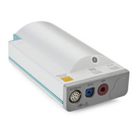
Philips M3000A Service Manual (293 pages)
M3/M4 Monitors,Measurement Server,Measurement Server Extensions
Brand:
Philips
| Category:
Measuring Instruments
| Size: 4.1 MB
Table of Contents
Sixth Edition
2
Seventh Edition
3
Table of Contents
9
1 Introduction to the Instrument
17
Objectives
17
Concepts
17
Introducing the Instrument Components
18
Instrument Components
20
A Quick Description of the Monitor
21
Front Panel Keys
21
Front of Monitor
21
Back of Monitor
22
A Quick Description of the Measurement Server
23
Overview of the Measurement Server
23
Measurement Connectors for the M3000A #C06, M3001A #C06
23
And #C18 Measurement Servers
23
Measurement Connectors for the Standard M3000A and M3001A Measurement Server
23
A Quick Description of the Measurement Server Extension
25
Overview of the Measurement Server Extensions M3015A & M3016A
25
Measurement Connectors for the M3015A Measurement Server Extension
25
Measurement Connectors for the M3016A Measurement Server Extension
26
A Quick Description of the Main Screen
26
Theories of Operation and Functional Descriptions
27
Section 1 - Monitor Description
27
Monitor Theory of Operation
28
Display and User Interface Software Module
29
Alarm Manager Software Module
29
Admit / Discharge / Transfer (ADT) Software Module
29
Trend Software Module
29
Events Software Module
29
Printer Manager
30
Recorder Manager
30
Irda/Serial Communication Manager
31
Communication Software Module
31
Support Services
31
Functional Description of the Monitor Hardware
32
Display Video Controller
33
Human Interface Controller
34
Battery Controller
34
ECG Out/Marker in Controller
34
Infrared (Irda) Interface
35
Serial Interface
35
Wireless LAN Interface
35
Section 2 - Measurement Server Description and Features
35
M3001A Measurement Server Standard Package
35
M3001A Measurement Server Extended Measurements Packages
36
M3000A Measurement Server Standard Package
36
M3000A #C06 Measurement Server Extended Measurements Package
36
Features
36
Measurement Server Theory of Operation
37
Functional Description of the Measurement Server Hardware
38
Electrocardiogram/Respiration (Ecg/Resp) Measurement
39
Description
39
Measurements
39
Ecg/Resp Features
40
Block Diagram of the Ecg/Resp
41
Theory of Operation
41
Non-Invasive Blood Pressure (NBP) Measurement
45
Description
45
Measurements
45
NBP Features
45
Block Diagram for NBP
47
Components
47
NBP Measurement Characteristic
48
Theory of Operation
48
Arterial Oxygen Saturation and Pleth (Spo 2 /PLETH) Measurement
49
Description
49
Measurements
49
Spo 2 /PLETH Features
49
Block Diagram of the Spo 2 /PLETH Circuit
50
Theory of Operation
50
Temperature and Invasive Blood Pressure (Temp/Press) Measurement
53
Description
53
Measurements
53
Temp/Press Features
53
Block Diagram
54
Theory of Operation
54
Temperature and Invasive Pressure Software
55
Block Diagram of the Temp/Press Software
56
Invasive Pressure Software Module
57
Temperature Software Module
58
Section 3 - Measurement Server Extensions Description and Features
60
Features
60
M3015A Measurement Server Extension Theory of Operation
61
Functional Description of the M3015A Measurement Server Extension Hardware
62
Hardware Block Diagram
63
Sidestream CO 2 Measurement
64
Description
64
Measurements
64
Sidestream CO 2 Features
65
Block Diagram of the Sidestream CO Measurement
67
Theory of Operation for M3015A Sidestream CO 2
67
M3016A Measurement Server Extension Theory of Operation
69
Functional Description of the M3016A Measurement Server Extension Hardware
70
Hardware Block Diagram
71
Mainstream CO 2 Measurement
72
Description
72
Measurements
72
Mainstream CO 2 Features
73
Block Diagram of the Mainstream CO 2 Measurement
75
Theory of Operation for the M3016A Mainstream CO 2
76
Tutorial for the Introduction to the Instrument
77
Answers to the Tutorial for the Introduction to the Instrument
78
2 Installing the Instrument
79
Objectives
79
Concepts
79
Safety
80
Patient Safety
80
Patient Leakage Current
80
Preparing to Install the Monitor
80
Power Source Requirements
80
Protecting against Electric Shock
80
Equipotential Grounding
81
Combining Equipment
81
Environment
82
Explanation of Symbols Used
83
Unpacking the Monitor
86
Installing the Monitor
86
Connecting the Measurement Server
87
With the Measurement Server Directly on the Monitor
87
With the Measurement Server Separate from the Monitor
89
Tension
90
Attaching the Monitor to a Mount
90
Detaching the Monitor from a Mount
90
Attaching the Measurement Server to a Mount
91
Detaching the Measurement Server from a Mount
91
Positioning the Measurement Server on a Clamp Mount
91
Connecting to the Nurse Call Relay
92
Modification for Nurse Call Alarm Relays
92
Verification Procedure
94
Installation of Wireless Infrastructure
94
Configuring the Radio Frequency of the M3/M4 Monitor
94
Connecting to the ECG Output or Marker Input
103
Configuring the Monitor
103
Selecting NBP Measurement Characteristic
103
Installing an Additional Display
106
Displays
106
Safety Specification
108
Installation
108
Installing the 12V Adapter
109
Using the Battery Charger and Conditioner
109
Connecting a Printer
109
Selecting a Printer
109
Installing the Wireless Infrared Printer Connector (M3080A #H05)
110
Connecting a Local Printer
111
Connecting a Remote Printer
112
Connecting a Local Recorder
112
Site Preparation Guidelines
113
Mounting Solutions
114
Installing the Table Mount (M3080A #A10)
114
Installing the Universal Bed Hanger (M3080A #A11)
115
Warnings, Cautions, and Safety Precautions Relating to Wall Mount Installation
116
Installing the Wall Rail (M3080A #A13)
117
Installing the Tilt/Swivel Mount (M3080A #A14)
117
Screwed Directly to a Wall
118
Mounted to the GCX Wall Channel (M3080A #A15)
119
Attached to a Universal Pole Clamp
120
Attached to the Monitor
121
Installing the GCX Wall Channel (M3080A #A15)
122
Installing the Universal Pole Clamp (M3080A #C05)
123
Installing the Measurement Server Mounting Options
124
Server Mounting Plate (M3080A #A01)
124
Server Mounting Plate (M3080A #A02)
127
Mounting Options for the Local Recorder
127
MSL Cable Termination
128
Disposing of the Monitor, Measurement Server and Measurement Server Extensions
131
Tutorial for Installing the Instrument
132
Answers to the Tutorial for Installing the Instrument
133
3 Maintaining the Instrument
135
Objectives
135
Concepts
135
Recommendations for Maintenance Frequency
136
Maintenance Checklist
137
Inspecting the Instrument
138
Inspect Cables and Cords
138
Inspect Cables, Cords and Housing
138
Preventive Maintenance Tasks
139
M3046A
139
M3000A / M3001A
139
Replacing the Backlight Tube Assembly
139
M3015A
140
Replacement of the Pump and CO 2 Scrubber
141
Replacement of the Pump and CO2 Scrubber
141
Replacement of the Infrared Lamp
141
General Cleaning of the Instrument
141
Cleaning Guidelines
141
Cleaning Agents
142
Battery Handling, Maintenance and Good Practices
143
About the Battery
143
Checking the Battery Status
143
Charging the Battery
145
Conditioning a Battery
146
Accessing the Battery Status Window
148
Battery INOP Messages
150
Tutorial for Maintaining the Instrument
151
Answers to the Tutorial for Maintaining the Instrument
152
4 Testing the Instrument
153
Objectives
153
Concepts
153
Test Reporting
154
Recommendations for Test Frequency
155
Test Map
156
Testing Checklist
157
Serial Numbers
158
Passwords
158
Visual Test
158
Power on Test
158
Functionality Assurance Tests
159
Performance Assurance Test
159
Quick System Check
159
System Self-Test
160
System Self-Test Values
161
Preventive Maintenance Tests
162
NBP Accuracy, Leakage, Linearity and Valve Test
162
Sidestream CO 2 Performance Test
164
Sidestream CO2 Performance Test
164
Checking and Resetting Time Counters
169
Documenting CO 2 Test Results
170
Accuracy and Performance Procedures
171
Temperature Accuracy
171
Ecg/Resp Performance
171
Invasive Pressure Performance Test
172
Spo Performance Test
173
Mainstream CO Performance Test
173
Nurse Call Relay Performance Test
173
Spo2 Performance Test
173
Mainstream CO2 Performance Test
173
ECG Sync Performance Test
174
Patient Safety Checks
175
Warnings, Cautions, and Safety Precautions
175
Safety Test Procedures
175
S(1) Part 1: System Enclosure Leakage Current - NC (Normal Condition)
176
S(1) Part 2: System Enclosure Leakage Current - Single Fault (Open Earth)
176
S(2) Protective Earth Continuity
177
S(3) Patient Leakage Current - Single Fault Condition (S.F.C.) Mains on Applied Part
178
Tutorial for Testing the Instrument
179
Answers to the Tutorial for Testing the Instrument
180
5 Troubleshooting the Instrument
181
Objectives
181
Concepts
181
Part 1 Troubleshooting Checklists
182
Checks for Obvious Problems
182
Checks before Opening the Instrument
182
First Steps
189
Initial Instrument Boot Phase
189
Isolating Problems to the Correct Subassembly
191
Part 2 Isolating and Solving Instrument Problems
193
INOP Messages
193
Isolating the Defective Component
199
Part 3 Using Support Functions
213
The Status Log and Error Codes
213
List of Error Codes
215
Testing Wireless Network Connectivity
220
Antenna Check
220
Using Service Mode
222
Service Mode Hardware Tests
222
How to Access the Monitor and Server Revision Screen
225
Troubleshooting the Installed Instrument
226
Troubleshooting with Self-Test Alarm Messages (When You Switch the Monitor On)
226
Troubleshooting When There Is no Message on the Screen
229
Troubleshooting During/After a Software Upgrade
230
Troubleshooting the Printer Connection
230
Troubleshooting the Recorder Connection
231
Tutorial for Troubleshooting the Instrument
233
Answers to the Tutorial for Troubleshooting the Instrument
234
6 Repairing the Instrument
235
Objectives
235
Concepts
235
Warnings, Cautions and Safety Precautions
236
General Reassembly/Refitting Comments
236
Disassembly for the Monitor
237
Removing the Battery
237
Removing the Power Supply
237
Removing the Chassis
238
Removing the System Board
240
Removing the Wireless Assembly (for Monitors with Wireless LAN Interface Only)
242
Removing the LCD Assembly and Backlight Tubes
242
Removing the Connector Board
244
Removing the Speaker
245
Refit Procedures for the Monitor
246
Refitting the System Board
246
Refitting the LCD Assembly and Backlight Tubes
246
Refitting the Connector Board
246
Refitting the Speaker
246
Refitting the Power Supply
246
Refitting the Wireless Assembly
247
Refitting the Chassis
247
Refitting the Battery
247
Disassembly Procedures for the M3015A Measurement Server Extension
248
Removing the Front Cover
248
Removing the Extension Bottom Cover
249
Removing the CO 2 Scrubber
251
Removing the Pump
252
Refit Procedures for the M3015A Measurement Server Extension
253
Refitting the CO 2 Scrubber
253
Refitting the Pump
254
Refitting the Extension Bottom Cover
254
Refitting the Front Cover
254
Disassembly Procedures for the M8043A Battery Charger and Conditioner
255
Opening the Housing
255
Removing the Cooling Fans
256
Removing the Air Filters
258
Reassembling the Battery Charger and Conditioner
258
Following Reassembly
258
Tutorial for Repairing the Instrument
259
Answers to Tutorial for Repairing the Instrument
260
7 Replacement Parts
261
Objectives
261
Compatibility Matrix - Release a to Release B
261
List of Replacement and Exchange Parts
263
Monitor Parts
264
Bezel Parts
264
Other Monitor Parts
266
Monitor Exchange Parts
267
Small Parts Kit
269
Multi-Measurement Server Parts
270
M3001A Part Numbers - Front Bezel
270
M3001A MMS Part Numbers - Intellivue Software Revision A.05.XX and Lower
272
M3001A MMS Part Numbers - Intellivue Software Revision A.10.XX and Higher
275
M3015A Measurement Server Extension Parts
282
M3015A Parts
282
M3015A Exchange Parts
284
M3016A Measurement Server Extension Parts
286
M3016A Parts
286
M3016A Measurement Server Extension Exchange Parts
287
Support-Related Parts
288
Cables and MSL through Wall Installation Parts
288
MMS Measurement Server Link (MSL) Cable Clamp Kit
289
Wireless Assembly Exchange Parts
289
Battery and Battery-Related Parts
290
Battery Parts
290
Battery Exchange Parts
290
Battery Charger and Conditioner Parts
290
XE-50P Recorder Exchange Parts
290
Advertisement
Advertisement
Related Products
Philips M3001A
Philips M3046A
Philips M1013A IntelliVue G1
Philips M1019A IntelliVue G5
Philips M300A
Philips M3014A
Philips M3016A
Philips M3012A
Philips M3046A M2
Philips M3046A M4
Philips Categories
TV
Monitor
Stereo System
Electric Shaver
CD Player
More Philips Manuals
Login
Sign In
OR
Sign in with Facebook
Sign in with Google
Upload manual
Upload from disk
Upload from URL