Table of Contents
Advertisement
Advertisement
Table of Contents
Troubleshooting

Related Manuals for Philips M1013A IntelliVue G1


Summary of Contents for Philips M1013A IntelliVue G1
- Page 1 Se r vi c e G ui de IntelliVue G1/G5 M1013A/M1019A Pa tie n t Monit o ring...
- Page 2 Part Number 4535 643 23271 Issued in Germany 02/2012 *453564323271*...
-
Page 3: Table Of Contents
Table of Contents 1 Introduction Who Should Use This Guide How To Use This Guide Description Responsibility of the Manufacturer Warnings and Cautions Physical Specifications Environmental Specifications MDD Classification Performance Specifications CO2 Measurement AWRR derived from CO2 Waveform N2O Measurement O2 Measurement Anesthetic Agent Measurement Alarm Ranges... - Page 4 IntelliVue Serial Port Configuration Altitude Configuration Connect Sample Input Tubing Post-Installation Checks Safety Requirements Compliance and Considerations Explanation of Symbols Used Electrical and Safety Requirements (Customer or Philips) Power Supply Requirements Protective Earthing of the System Equipotential Grounding Combining Equipment Connecting Non-Medical Devices...
- Page 5 System Test What is a Medical Electrical System General Requirements for a System Preventive Maintenance Procedures Cleaning Replace PM Parts Replacing the Fan Filter Replacing the Watertrap Manifold Seals Performance Assurance Tests - Checking and Calibrating the Gas Analyzer Access Service Functions of the Gas Analyzer When and how to check the Gas Analyzer Equipment required for checking Annual Checks...
- Page 6 Tools required Removing the Bottom Quick Release Mount 7 Parts List Exchange Parts Replacement Parts...
-
Page 7: Introduction
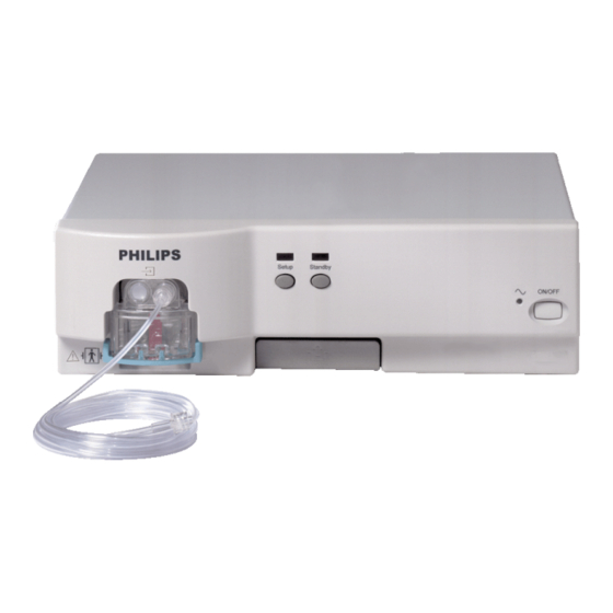
In addition, scrolling through the topics with the page up and page down keys is also possible. Description The Philips M1013A IntelliVue G1 and the M1019A IntelliVue G5 work together with the IntelliVue patient monitors through an RS232 serial interface. They measure the airway gases of ventilated patients who are under general gas anesthesia, or emerging from it. -
Page 8: Responsibility Of The Manufacturer
• the instrument is used in accordance with the instructions for use. To ensure safety and EMC, use only those Philips parts and accessories specified for use with the monitor. If non-Philips parts are used, Philips is not liable for any damage that these parts may cause to the equipment. -
Page 9: Environmental Specifications
Environmental Specifications 1 Introduction Environmental Specifications Operating Temperature: 10 to 40C (50 to 104F) Storage Temperature: -20 to 65C (-4 to 149F) Humidity Limit (Operating): 5 to 90% RH max @ 40C (104F). non-condensing Humidity Limit (Storage): 5 to 95% RH max @ 65C (149F). non-condensing Altitude Range (Operating): -305 to 2900m (-1,000 to 9,515ft) -
Page 10: Co2 Measurement
1 Introduction Performance Specifications Measurement Range: 0 to 76 mmHg 0.5 vol% or 12% relative, whichever is greater Accuracy: Resolution: 1 mmHg Rise-time: 350 msec typical AWRR derived from CO Waveform Range: 0 to 60 rpm Accuracy: ± 1 rpm Resolution: 1 rpm Detection Criteria:... -
Page 11: Alarm Ranges
Performance Specifications 1 Introduction Agent ID Response Time 14 s for first agent, 19 s for second agent First Agent All agents max. 0.3 vol% Detection / Identification Threshold Second Agent All agents max. 0.4 vol% of a second agent, except if a Detection / second agent is added to Desflurane, this causes Identification... -
Page 12: Inop Alarms
• No breath detected. Theory of Operation General Measurement Principles The M1013A IntelliVue G1 and the M1019A IntelliVue G5 use infrared technology to measure the concentration of the gases CO O and the volatile anesthetic agents. The gases which can be measured by the gas analyzer absorb infrared (IR) light. Each gas has its own absorption characteristic. -
Page 13: Pump
Theory of Operation 1 Introduction Gases with paramagnetic properties are attracted by magnetic fields. In a magnetic field the density and thus the heat conductivity of such gases is increased. The gas analyzer determines the amount of oxygen in the gas sample by measuring its heat conducting properties while switching a magnetic field on and off inside the O sensor. - Page 14 1 Introduction Theory of Operation The watertrap itself includes “water fuses” in both the “measurement” and the “drainage” paths, consisting of a material that swells when getting wet (when the reservoir is full or when fluid penetrates the separation filter and enters the “measurement” path) and blocks the respective path at the inlet of the unit.
-
Page 15: Installation And Patient Safety
Installation and Patient Safety The M1013A IntelliVue G1 and the M1019A IntelliVue G5 must be installed by qualified personnel N O T E capable of performing the post-installation checks as outlined in the Test and Inspection Matrix This chapter describes how to install the Philips M1013A IntelliVue G1 and the M1019A IntelliVue G5. -
Page 16: Environment
2 Installation and Patient Safety Environment Environment Possible explosion hazard if used in the presence of flammable anesthetics. WARNING The environment where the gas analyzer is used should be free from vibration, dust, corrosive or explosive gases, and extremes of temperature and humidity. For a cabinet mounted installation with the monitor, allow sufficient room at the front for operation and sufficient room at the rear for servicing with the cabinet access door open. -
Page 17: Claims For Damage And Repackaging
Repackaging for Shipment or Storage If the instrument is to be shipped to a Philips Sales/Support Office, securely attach a label showing the name and address of the owner, the instrument model and serial numbers, and the repair required (or symptoms of the fault). -
Page 18: Connecting The Intellivue G1/G5 To Ac Mains
2 Installation and Patient Safety Making Connections to the IntelliVue G1/G5 – M1019A#K11 1.5 m (M1013-61001) – M1019A#K12 3 m (M1013-61002) Equipotential Grounding Terminal; this is used to connect the gas analyzer to the hospital’s equipotential grounding system. Gas exhaust. If N O and/or other inhalation anesthetics are used during anesthesia, pollution of the operating room should be prevented. -
Page 19: Securing The Power Cord
Making Connections to the IntelliVue G1/G5 2 Installation and Patient Safety Securing the Power Cord In order to prevent the power cord from accidentally being unplugged, secure it with the power cord securing bracket. Insert the nose of the power cord securing bracket into the small slit above the power connector. Slide the bracket to the left and secure it with knurled nut. -
Page 20: Connections To The Sample Gas Exhaust
2 Installation and Patient Safety Connections to the Sample Gas Exhaust Connections to the Sample Gas Exhaust Returning the Gas Sample You will need the following equipment to return the gas sample to the anesthesia circuit: Equipment Part Number Comments Gas Exhaust Return Line M1655B Tubing includes two parts:... -
Page 21: Removing The Gas Sample
Installing the Top Mount 2 Installation and Patient Safety Make sure the sample gas is routed through the CO absorber before going back to the patient. N O T E M1656B Gas Exhaust Return Filter Female luer lock Shorter tube connecting to the ventilation circuit Longer tube connecting to the Anesthetic Gas Exhaust Outlet Removing the Gas Sample To remove the gas sample from the anesthesia circuit, a scavenging system needs to be connected to the... -
Page 22: Mounting Instructions
There are different mounting options available for the IntelliVue G1 / G5. This section covers the N O T E general concepts of safe mount installations and specific steps for the mounting options sold by Philips. Instructions which ship with a mounting solution should always take precedence over the instructions described in this chapter. -
Page 23: Setup And Configuration Procedures
Safety Requirements Compliance and Considerations The M1013A IntelliVue G1 and the M1019A IntelliVue G5 comply with the following international safety requirements for medical electrical equipment: IEC 60601-1:1988 + A1:1991 + A2:1995; EN60601-1:1990 + A1:1993 + A2:1995; UL 60601- 1:2003;... -
Page 24: Explanation Of Symbols Used
The IntelliVue G1 and the IntelliVue G5 are protected against the effects of defibrillation and electrosurgery. Electrical and Safety Requirements (Customer or Philips) Power Supply Requirements The system and the gas analyzer can both be operated from an AC supply of 100 - 240V ±10%, 50 -... -
Page 25: Protective Earthing Of The System
Safety Requirements Compliance and Considerations 2 Installation and Patient Safety Protective Earthing of the System To protect the patient and hospital personnel, the cabinet of the installed equipment has to be grounded. The equipment is supplied with a detachable 3-wire cable which grounds the instrument to the power line ground (protective earth) when plugged into an appropriate 3-wire receptacle. - Page 26 2 Installation and Patient Safety Safety Requirements Compliance and Considerations...
-
Page 27: Software Uploads
Software Uploads For a software update of the M1013A IntelliVue G1 and M1019A IntelliVue G5 you need the most recent software as listed in the Service Bulletin (SB) or Field Change Order (FCO) and download it from the SoftServer as described there. Save it to a folder where it is easy to find, for example C:/TEMP. -
Page 28: Checking The Unit For Functionality
3 Software Uploads Checking the Unit for Functionality Checking the Unit for Functionality Before performing a software update, please check the IntelliVue G1/G5 for functionality by following the steps listed below. 1) Set Standby to Operate and breath detection to Disabled in General Tab. - Page 29 Checking the Unit for Functionality 3 Software Uploads 2) Then select the Pneum. Tab and set Pump Flow Level to high. 3) Select the Zero Tab and set the calibration mode to Auto. 4) Wait for the automatic Zero calibration to start or choose Manual and press the “Zero” button. Please make sure to switch the calibration mode back to Auto after a successful Zero calibration.
- Page 30 3 Software Uploads Checking the Unit for Functionality should be approximately 0.03 Vol. %, O should be approximately 20.8 Vol. %, N O and Agent 1 and 2 should be 0 Vol. %. Data valid will have a green LED; ISO accuracy will have a yellow LED for a successful calibration.
- Page 31 6) Check the software configuration in the Config. Tab: Expand the MOPS item in the Component Info window to check the Software rev. (e.g. 1.25.00 before upload) and then go to the MFM item (except for M1013A IntelliVue G1 without O option) below and expand that as well. Check the...
-
Page 32: Uploading The Software
3 Software Uploads Uploading the Software Uploading the Software 1) After checking the unit, please select the MISC Tab in the VISIA tool. In the DOWNLOAD section, click on the START button. - Page 33 Uploading the Software 3 Software Uploads 2) Next a pop-up window will open. Click on the Select button and choose the first software file from the folder to which it was downloaded. Both software files must be loaded to the device (except for M1013A without O option).
- Page 34 3 Software Uploads Uploading the Software...
- Page 35 Uploading the Software 3 Software Uploads While loading, please do not interrupt the Power Supply. Do not disconnect the serial line. This may CAUTION destroy the memory in the module and the module will need to be exchanged and repaired. 4) When the download is finished, the programming process will automatically start, as indicated in the Status section ("…programming in progress…...
- Page 36 3 Software Uploads Uploading the Software 5) When the first file upload is complete(see picture below), please do not click on the OK button (except for M1013A without O2 option). For M1013A with O2 option and M1019A the second software file must be loaded and programmed...
- Page 37 Uploading the Software 3 Software Uploads 6) Click on Select again, and choose the second software file. Then click on the Start button.
- Page 38 3 Software Uploads Uploading the Software 7) Follow the same steps as with the first file. When the programming process is finished click on the OK button. After download and programming is complete, the connection will be lost. You will need to reconnect N O T E in the General Tab in order to check whether the software upload was successful.
- Page 39 Uploading the Software 3 Software Uploads 9) For checking the software, select the Config. Tab and expand MOPS and MFM again.
- Page 40 3 Software Uploads Uploading the Software In MOPS you should see the new software, e.g. Software Rev.: 1.32.00 and in MFM the new software for the Multi Function Module, e.g. Software Rev.: 2.15.00 (except for M1013A without O2 option, there you will only need to check the MOPS section). 10) The software file(s) are now successfully loaded and programmed.
-
Page 41: Testing And Maintenance
Testing and Maintenance Introduction This chapter provides a checklist of the testing and maintenance procedures to ensure the performance and safety of the IntelliVue G1/G5. These tests must be performed only by qualified personnel certified by the responsible organization. Qualifications required are: training on the subject, knowledge, experience and acquaintance with the relevant technologies, standards and local regulations. -
Page 42: Recommended Frequency
It is the responsibility of the facility operator or their designee to obtain reference values for recurring N O T E safety and system tests. These reference values are the results of the first test cycles after an installation. You may also purchase this service from Philips. -
Page 43: Testing Sequence
Testing Sequence 4 Testing and Maintenance Testing Sequence Visual Inspection Before Each Use Check all exterior housings for cracks and damage. Check the condition of all external cables, especially for splits or cracks and signs of twisting. If serious damage is evident, the cable should be replaced immediately. -
Page 44: Power On Test
4 Testing and Maintenance Safety Tests • the integrity of all relevant accessories. Power On Test Switch on gas analyzer and patient monitor and check for any INOP messages after the warmup phase. Make sure that the gas analyzer is not in Standby. Wait for 12 minutes and make sure that no gas analyzer related INOP messages appear (except “GM No Breath”, “GM Alarm Suppress”, “GM CAL RUNNING”... -
Page 45: Safety Test Procedures
Safety Tests 4 Testing and Maintenance • For Europe and Asia/Pacific, the monitor complies with: IEC 60601-1:1988 + A1:1991 + A2:1995; EN60601-1:1990 + A1:1993 + A2:1995; IEC 60601-1- 1:2001; EN 60601-1-1:2001; IEC 60601-1-2:2001; EN 60601-1-2:2001. For USA, the monitor complies with: UL60601-1 For Canada, CAN/CSA C22.2#601.1-M90 •... - Page 46 4 Testing and Maintenance Safety Tests The following symbols are used in the diagrams illustrating the safety tests: Supply mains Protective earth L, N Supply mains terminals Protective earth terminal Mains part Applied part F-type applied part Measuring device Resistance measuring device Connection to accessible conductive parts ..
-
Page 47: Hints For Correct Performance Of Safety Tests
Safety Tests 4 Testing and Maintenance Hints for Correct Performance of Safety Tests • Perform a visual inspection on all detachable power cords used with the monitoring system and include these in all safety test procedures. • Connection lines such as data lines or functional earth conductors may appear to act like protective earth connections. -
Page 48: Electrical Safety Testing
4 Testing and Maintenance Electrical Safety Testing Figure 5 Equipment Leakage Current Test - Setup Example N O T E The test lead needs to go to the grounded enclosure parts, the ungrounded enclosure parts and all of the applied parts connected together. N O T E The above graphics resemble the Metron QA-90 setup and are protected by copyright. -
Page 49: S(2) Equipment Leakage Current Test - Normal Condition
Electrical Safety Testing 4 Testing and Maintenance This measures the impedance of the Protective Earth (PE) terminal to all exposed metal parts of the Device under Test (DUT), which are for safety reasons connected to the Protective Earth (PE). You can find metal parts of the device at the equipotential connector. Measurements shall be performed using a measuring device capable to deliver a current of at least 200 mA into 500 mOhms with maximum open circuit voltage of 24V This safety test is based on IEC/EN 62353. -
Page 50: S(3) Equipment Leakage Current Test - Single Fault Condition
4 Testing and Maintenance Electrical Safety Testing This safety test is based on IEC/EN 62353. For measurement limits, refer to Safety (2) test, Test and Inspection Matrix. Report the highest value (X1). Test Expected Test Results Equipment Leakage Current Test (Normal X1 <= 100A Condition - with mains cable) All values for current and voltage are the root mean square (r.m.s.) values, unless otherwise stated. -
Page 51: Reference: Allowable Values For Iec 60601-1:1998 And Ul 60601-1 Measurements
System Test 4 Testing and Maintenance Test Expected Test Results Equipment Leakage Current Test (Single X2 <= 300A Fault Condition - with mains cable) N O T E All values for current and voltage are the root mean square (r.m.s.) values, unless otherwise stated. In case of an IT-power system, this safety test measurement requires a special measuring circuit, for example with its own integrated TN-system or use of an external isolation transformer attached to the safety test device. -
Page 52: General Requirements For A System
4 Testing and Maintenance Preventive Maintenance Procedures General Requirements for a System After installation or subsequent modification, a system must comply with the requirements of the system standard IEC/EN 60601-1-1 or IEC 60601-1 edition 3 clause 16. Compliance is checked by inspection, testing or analysis, as specified in the IEC/EN 60601-1-1 or in this book. -
Page 53: Replace Pm Parts
Preventive Maintenance Procedures 4 Testing and Maintenance Never leave the gas analyzer running without the watertrap attached, as sucked in dust or cleaning CAUTION agents may irreparably damage the instrument. Ideally, switch off the gas analyzer or go into Standby mode when cleaning the instrument. -
Page 54: Performance Assurance Tests - Checking And Calibrating The Gas Analyzer
Equipment required for checking The following equipment is required for checking the gas analyzer. If applicable, part numbers are given in the parts list section of this manual. Equipment Philips part # or other recommendation Accuracy IntelliVue G1/G5 PC cable M1013-61005 / 451261005001 (RS232 - if necessary, a USB-to-RS232 serial adapter can be used. - Page 55 Performance Assurance Tests - Checking and Calibrating the Gas Analyzer 4 Testing and Maintenance If your PC/Laptop does not have an RS232 serial connector, you can use a USB-to-RS232 Serial N O T E adapter. For the COM port settings, you need to change the USB Serial port to COM1. To do this: Go to Control Panel ->...
-
Page 56: Annual Checks
4 Testing and Maintenance Performance Assurance Tests - Checking and Calibrating the Gas Analyzer Annual Checks Perform the following procedure once a year Connect a PC/Laptop running the Service Software (VISIA tool) to the instrument and wait for the first zero calibration after the start up period. (Make sure that zero mode is switched to Auto - see “Zero Calibration”... - Page 57 Performance Assurance Tests - Checking and Calibrating the Gas Analyzer 4 Testing and Maintenance switch Pump Flow Level to High (as shown in Figure 8). Figure 7 General Tab in VISIA tool...
- Page 58 4 Testing and Maintenance Performance Assurance Tests - Checking and Calibrating the Gas Analyzer Figure 8 Pneumatic Tab in VISIA tool...
-
Page 59: Zero Calibration
The IntelliVue G1 and G5 require a periodic zero calibration. Whenever this is due, the instrument sends a zero request command to the host monitor. The Philips patient monitor automatically initiates a zero calibration whenever it receives such a request from the gas analyzer - if you want the VISIA tool to do the same, you have to switch the zero mode from Manual to Auto (see Figure 9). -
Page 60: Component Status Check
4 Testing and Maintenance Performance Assurance Tests - Checking and Calibrating the Gas Analyzer Test Expected Test Results Zero Calibration Test Zero succesful and green soft-LEDs in the Zero Status area Component Status Check Figure 10 Component Status Check with the Status Tab in VISIA Tool Wait for the first automatic zero calibration to complete (for details on automatic zero calibrations refer to “Zero Calibration”... -
Page 61: Pneumatic Tests
Performance Assurance Tests - Checking and Calibrating the Gas Analyzer 4 Testing and Maintenance Test Expected Test Results Component Status Check Module INOP and Any Component Fail show green soft-LEDs Pneumatic Tests These tests ensure the integrity of the pneumatics system, which has a big impact on the quality of the measured values. - Page 62 4 Testing and Maintenance Performance Assurance Tests - Checking and Calibrating the Gas Analyzer Connect the shortest piece of tubing to the watertrap and then connect the syringe (20 ml) to the 3-way stopcock as shown below. Make sure that this connection is tight.. Shortest Tubing Syringe Connection...
- Page 63 Performance Assurance Tests - Checking and Calibrating the Gas Analyzer 4 Testing and Maintenance Kit Leak Test Procedure: Form a loop with the leakage test kit as shown in the picture below. Use the female luer thread/luer slip to attach the long tubing to the watertrap tubing. Connect a syringe to the 3-way stopcock and a digital pressure indicator to the open tubing.
-
Page 64: Flow Rate Check
4 Testing and Maintenance Performance Assurance Tests - Checking and Calibrating the Gas Analyzer Flow Rate Check For this check, always measure the gas analyzer flow rate at the sample gas inlet. Measuring at the outlet CAUTION may lead to incorrect flow readings due to ripple on the gas flow. Test Procedure: •... -
Page 65: Flow Rate Adjustment
Performance Assurance Tests - Checking and Calibrating the Gas Analyzer 4 Testing and Maintenance Test Expected Test Results Pressure Sensor Test Deviation between the two measured values is <10mbar Flow Rate Adjustment For this adjustment, always measure the gas analyzer flow rate at the gas sample inlet. Measuring at the CAUTION outlet may lead to incorrect flow readings due to ripple on the gas flow. -
Page 66: Gas Calibration Test
4 Testing and Maintenance Performance Assurance Tests - Checking and Calibrating the Gas Analyzer Figure 11 Flow Rate Adjustment The Restore Old button brings back the last saved flow rate. Once a new flow rate has been saved, only this flow rate can be recalled when attempting to restore an old one. Gas Calibration Test The gas analyzer should run for at least 6 minutes until the Data soft-LED in the Patient Data reads Data Valid before continuing with the following calibration procedures. - Page 67 Performance Assurance Tests - Checking and Calibrating the Gas Analyzer 4 Testing and Maintenance Flow Regulator M2211A Attach Sample Tubing here Reservoir Bag M1659A Gas Bottle M1662A Figure 12 Span Checking Equipment including Gas Canister and Spray Valve The procedure to check the gas accuracy is as follows: Set Breath Detection to Disabled in the General Tab.
- Page 68 4 Testing and Maintenance Performance Assurance Tests - Checking and Calibrating the Gas Analyzer Figure 13 Patient Data Window during Gas Calibration Test Now compare the numeric values shown in the lower section of the Patient Data Window with the concentrations as printed on the calibration gas canister.
-
Page 69: Disposal Of Empty Gas Cylinder
Philips recommends all test results are documented in accordance with local laws. Authorized Philips personnel report the test result back to Philips. While hospital personnel (biomedical engineers or technicians) do not need to report results to Philips, Philips recommends that they record and store the test results in accordance with local laws. -
Page 70: Carrying Out And Reporting Tests
4 Testing and Maintenance Reporting of Test Results • The actual tests (incl. visual inspections, performance tests, safety and system tests) and measurements required • Date of testing and of the concluding evaluation. • A record of the actual values of the test results, and whether these values passed or failed the tests. •... -
Page 71: Test And Inspection Matrix - Checks With Patient Monitor
Reporting of Test Results 4 Testing and Maintenance Test and Inspection Matrix - Checks with Patient Monitor Test Block Name Test or Inspection to be performed Expected Test Result What to Record on Service Record Visual Check Check for any mechanical damage and all Expected answer is "yes". - Page 72 4 Testing and Maintenance Reporting of Test Results Test Block Name Test or Inspection to be performed Expected Test Result What to Record on Service Record Safety (3) Perform Safety Test (3): Equipment Leakage With mains cable: S(3):P/X2 or Current - Single Fault Condition (Open Maximum impedance (X2): S(3):F/X2 <= 300 A)
-
Page 73: Checks With Visia Tool
Reporting of Test Results 4 Testing and Maintenance Checks with VISIA Tool Test Block Name Test or Inspection to be performed Expected Test Result What to Record on Service Record Zero Calibration Is the status of the zero calibration "Zero Expected answer is "yes". -
Page 74: Evaluation Of Test Results
4 Testing and Maintenance Other Regular Tests Notes Next Recurrent Test: Name:____________________________________________________ Date/Signature:_____________________________________________ Evaluation of Test Results The evaluation of the test results must be performed by appropriately trained personnel with sufficient product, safety testing and application knowledge. If any test results are between 90% and 100% of the respective expected result, the previously measured reference values must be taken into consideration for the assessment of the electrical safety of the device under test. -
Page 75: Troubleshooting The Gas Analyzer
It details how to proceed when errors are flagged for: • Failed calibration checks and procedures • Failed diagnostic checks. Equipment needed for troubleshooting: Equipment Philips part # or other recommendation Accuracy IntelliVue G1/G5 PC cable M1013-61005 / 451261005001 3 ml/min or better... -
Page 76: Technical Alarm Messages (Inops)
5 Troubleshooting the Gas Analyzer Technical Alarm Messages (INOPs) Technical Alarm Messages (INOPs) INOP Message, Indication What to do If zero is suspended, gas analyzer measurement accuracy may be GM ACCURACY? Numerics shown with -?- reduced. Check that the gas inlet, watertrap, and gas outlet tubing are not occluded. - Page 77 Technical Alarm Messages (INOPs) 5 Troubleshooting the Gas Analyzer INOP Message, Indication What to do A gas analyzer component is in malfunction. Some parameters may be GM COMPONENT MALF unavailable or measured with reduced accuracy. Switch the gas analyzer Numerics shown with -?- off and then on again.
-
Page 78: Troubleshooting
5 Troubleshooting the Gas Analyzer Troubleshooting INOP Message, Indication What to do The O wave is clipped. Select a more appropriate wave scale to display CHANGE SCALE the whole wave. The O value is higher than the measurement range. If you suspect a OVERRANGE Numerics replaced by -?-, INOP tone false high value, follow the troubleshooting procedure described in this... -
Page 79: Repairing The Gas Analyzer
Only qualified service personnel should open the IntellIVue G1 / G5 housing, remove and replace components, or make adjustments. If your medical facility does not have qualified service personnel, contact Philips’ Response Center or your local Philips representative. • Switch off the instrument and disconnect it from the mains power supply. Take standard WARNING electrostatic precautions. - Page 80 6 Repairing the Gas Analyzer Removing the Bottom Quick Release Mount Removing the Bottom Quick Release Mount Remove the two screws securing the bottom quick release mount. Lift out the mount.
-
Page 81: Parts List
Parts List This chapter provides the replacement and exchange part numbers (if available) for the Philips M1013A IntelliVue G1 and the M1019A IntelliVue G5 and calibration equipment. Refer to the following table to identify the part and part number. Exchange Parts... - Page 82 7 Parts List Replacement Parts CMS Part Number 12NC Part Number Description M1013-61003 451261006231 IntelliVue cable 10 m M8000-64100 451261001381 Table Mount (for top of gas analyzer) 453564227351 Mounting Assembly (for bottom of gas analyzer) M1013-01201 451261006261 Power Cord Securing Bracket...
- Page 83 Index Power On Test power supply gas input symbol requirements Alarm limit ranges gas output symbol pre-use checks Alarm Ranges gas sample Preventive Maintenance input tubing alternating current symbol Pump removing altitude configuration general description Anesthetic Gas Exhaust Grounding Apnea rear panel connectors AWRR repairing...
Need help?
Do you have a question about the M1013A IntelliVue G1 and is the answer not in the manual?
Questions and answers