
Related Manuals for Keithley 6517B


Summary of Contents for Keithley 6517B
- Page 1 Model 6517B Electrometer Reference Manual 6517B-901-01 Rev. D / February 2016 *P6517B90101D* 6517B-901-01 A Great e r M ea s u re of C on f i de n c e...
- Page 2 , and TSP-Net are trademarks of Keithley Instruments. All Keithley Instruments product names are trademarks or registered trademarks of Keithley Instruments. Other brand names are trademarks or registered trademarks of their respective holders. The Lua 5.0 software and associated documentation files are copyright © 1994 - 2015, Lua.org, PUC-Rio.
-
Page 3: Safety Precautions
Keithley Instruments products are designed for use with electrical signals that are measurement, control, and data I/O connections, with low transient overvoltages, and must not be directly connected to mains voltage or to voltage sources with high transient overvoltages. - Page 4 (note that selected parts should be purchased only through Keithley Instruments to maintain accuracy and functionality of the product). If you are unsure about the applicability of a replacement component, call a Keithley Instruments office for information.
-
Page 5: Table Of Contents
Table of Contents Getting started ......................1-1 Welcome ..........................1-1 Capabilities and features overview ..................1-1 Available options and accessories ..................1-2 Cables and adapters ......................... 1-3 Case and rack mount kits ......................1-4 Probes ............................ - Page 6 Floating measurements ......................3-10 Floating voltage source ......................3-10 Test fixtures ........................3-11 Keithley Instruments Model 8009 test fixture................3-11 Custom built test fixtures ......................3-12 Basic measurements ....................4-1 Introduction .......................... 4-1 ...
- Page 7 Model 6517B Electrometer Reference Manual Table of Contents Electromagnetic interference (EMI) ..................4-38 Relative humidity and external temperature readings ............. 4-39 Measurement options ....................5-1 Introduction .......................... 5-1 Voltage source ........................5-1 V-Source configuration ......................5-2 ...
- Page 8 Table of Contents Model 6517B Electrometer Reference Manual Trigger models ........................7-3 Basic trigger model ........................7-4 Advanced trigger model ......................7-6 Trigger model layers ......................... 7-7 Trigger configuration ......................7-9 Basic trigger configuration ......................7-9 Advanced trigger configuration ....................
- Page 9 *IDN? (identification query) ..................... 12-7 *OPC (operation complete) ..................... 12-8 *OPC? (operation complete query) ..................12-9 *OPT? (option identification query) ..................12-10 *RCL (recall) .......................... 12-10 *RST (reset the Model 6517B) ....................12-10 ...
- Page 10 Table of Contents Model 6517B Electrometer Reference Manual *SAV (save the current setup in memory) ................12-11 *SRE <NRf> (service request enable), *SRE? (service request enable query) ..... 12-11 *STB? (status byte query) ..................... 12-13 *TRG (trigger) ........................12-14 ...
- Page 11 Model 6517B Electrometer Reference Manual Table of Contents :MA2Factor <NRf> ........................ 14-34 :PERCent <NRf> ........................14-34 :REFerence <NRf> ........................ 14-35 :STATe <b> ........................... 14-35 DATA commands ........................14-35 [:LATest]? ..........................14-35 :FRESh? ..........................14-36 ...
- Page 12 Table of Contents Model 6517B Electrometer Reference Manual Ohms ranges: ........................14-66 [:UPPer] <n> ......................... 14-66 :AUTO <b>|ONCE ......................... 14-67 :ULIMit <n> ..........................14-67 :LLIMit <n> ..........................14-68 :VSOurce:RANGe <n> ......................14-69 :VSOurce[:AMPLitude] <n> ....................14-70 ...
- Page 13 Model 6517B Electrometer Reference Manual Table of Contents [:INTernal] <list> ........................14-96 :EXTernal <n> ........................14-97 :LSELect <name> ......................... 14-97 :STIMe <n> ........................... 14-98 :SMEThod <name> ....................... 14-98 :VSLimit <b> .......................... 14-99 :STATus subsystem ......................14-99 ...
- Page 14 Table of Contents Model 6517B Electrometer Reference Manual :[PERCent] <n> ........................14-140 :READings <b> ........................14-141 :SOURce <name> ....................... 14-141 :CONTrol <name> ....................... 14-142 :DATA? ..........................14-142 :LAST? ..........................14-143 :TSTamp:FORMat <name> ....................14-143 ...
- Page 15 Model 6517B Electrometer Reference Manual Table of Contents :TEMPerature <name> ......................14-172 Calibration procedure ....................15-1 Introduction ........................15-1 Calibration Procedure ......................15-1 Environmental conditions ......................15-1 Warm-up period ........................15-2 Recommended calibration equipment ..................15-2 ...
- Page 16 Table of Contents Model 6517B Electrometer Reference Manual Calculating resistance/resistivity accuracy and repeatability using the alternating polarity methodA-4 Interface function codes ....................B-1 Interface function codes ....................... B-1 Code summary .......................... B-1 Code descriptions ........................B-2 ASCII character codes ....................C-1 ...
-
Page 17: Getting Started
Manual, also provided on the supplied product information CD in PDF format, is an abbreviated version of the operation sections of this Reference Manual. This section contains general information about the Keithley Instruments Model 6517B Electrometer. Capabilities and features overview The Model 6517B is a 6½-digit Electrometer/high-resistance system with the following measurement... -
Page 18: Available Options And Accessories
Available options and accessories Check the Keithley Instruments website (www.keithley.com) for additional options and accessories that may have been added to the Keithley Instruments product line for use with the Model 6517B Electrometer. The following options and accessories are available from Keithley Instruments for use with the Model 6517B Electrometer. -
Page 19: Cables And Adapters
Model 7078-TRX-BNC Adapter: This is a 3-slot male triaxial to female BNC adapter. This adapter lets you connect a BNC cable to the triaxial input of the Model 6517B. Suitable for use with the Model 6517B in high voltage applications. -
Page 20: Case And Rack Mount Kits
Model 1050 Padded Carrying Case: A carrying case for a Model 6517B. Includes handles and shoulder strap. Model 4288-1 Single Fixed Rack Side Mount Kit: Mounts a Model 6517B in a standard 19 inch rack. Model 4288-2 Dual Fixed Rack Side Mount Kit: Mounts two Model 6517B instruments in a standard 19 inch rack. -
Page 21: Manual Addenda
Model 6517B Electrometer Reference Manual Section 1: Getting started Manual addenda Any improvements or changes concerning the Model 6517B or manuals is explained in an addendum included with the manual. Be sure to note these changes and incorporate them into the manual. Extended warranty Additional years of warranty coverage are available on many products. -
Page 22: General Ratings
After removing the Model 6517B from its anti-static bag, inspect it for any obvious signs of physical damage. Report any such damage to the shipping agent immediately. When the Model 6517B is not installed and connected, keep the unit in its anti-static bag and store it in the original packing carton. Shipment contents The following items are included with every Model 6517B order: ... -
Page 23: Repacking For Shipment
Section 1: Getting started Repacking for shipment Should it become necessary to return the Model 6517B for repair, carefully pack the unit in the original packing carton or the equivalent, and follow these instructions: Get a Return Material Authorization (RMA) number; please contact your local Keithley Instruments office, sales partner, or distributor. -
Page 24: Getting Started
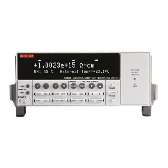
Instruments Model 6517B Electrometer and detailed information for powering up the Model 6517B. Front panel summary The front panel of the Model 6517B is shown below. The descriptions of the front panel controls follow. Figure 1: Model 6517B front panel... - Page 25 EXIT: Cancels selection, moves back within menu structure. ENTER: Holds reading, enters selection, moves down within menu structure. VOLTAGE SOURCE KEYS OPER: Toggles V-source between operate and standby. Increase and decrease keys: Adjusts V-source value. 6517B-901-01 Rev. C / August 2015...
-
Page 26: Rear Panel Summary
Use to program and operate an installed option. Also used to scan external scanner channels. Rear panel summary The rear panel of the Model 6517B is shown in the following figure. The descriptions of the rear panel components follow. Figure 2: Model 6517B rear panel INPUT CONNECTOR ... - Page 27 Connects the safety interlock to a test fixture using an appropriate cable. Interlock is automatically enabled when the appropriate interlock cable is connected to the Model 6517B. Rated at 50 Hz to 60 Hz, 140 VA max. The interlock’s CS-1305 connector includes four pins (left to right as viewed from rear of the Model 6517B): ...
-
Page 28: Power-Up
Line voltage is pre-set at the factory, but may be reset in the field by adjusting the voltage selector behind the left ear (when looking at the front panel of the Model 6517B). To access the voltage selector, first remove the handle then remove the left mounting ear. The current voltage setting is the marking closest to the small circle. -
Page 29: Power-Up Sequence
For 100 V and 120 V line voltage, use a 0.630 A, 250 V, 5 mm x 20 mm fuse (Keithley P/N: FU-106-.630). For 220 V and 240 V line voltage, use a 0.315 A, 250 V, 5 mm x 20 mm fuse (Keithley P/N: ... - Page 30 MENU key. Warmup period You can use the Model 6517B within one minute after it is turned on. However, the instrument should be turned on and allowed to warm up for at least one hour before use to achieve rated accuracy.
-
Page 31: Display
0 to 30 by using the MENU key. Display The display of the Model 6517B is primarily used to display readings along with the units and type of measurement. When not displaying readings, it is used for informational messages, such as menu headings and selections. -
Page 32: Range Messages
20 nA range" figure. Clipping occurs at 110 % of full range (22 nA on the 20 nA range). Because of clipping, the measurement of the input signal is significantly less than 20 nA. To avoid these bad readings, the Model 6517B displays the OUT OF LIMITS message instead of the inaccurate reading. - Page 33 Section 2: Getting started Model 6517B Electrometer Reference Manual Figure 3: Input signal Figure 4: Measurement on 20 nA range 2-10 6517B-901-01 Rev. C / August 2015...
-
Page 34: Status And Error Messages
Section 2: Getting started Status and error messages During Model 6517B operation and programming, you encounter a number of front panel messages. Typical messages are either of status or error variety, as listed in the table below. The most recent status or error messages can be momentarily displayed by entering a configuration menu or the main menu, and pressing the PREV display key (the display is blank if no message is queued). - Page 35 "Waiting in arm layer 2" +174 "Re-entering the idle layer" +301 "Reading overflow" +302 "Low limit 1 event" +303 "High limit 1 event" +304 "Low limit 2 event" +305 "High limit 2 event" 2-12 6517B-901-01 Rev. C / August 2015...
- Page 36 "RS-232 Break detected" +804 "RS-232 Noise detected" +805 "Invalid system communication" +806 "RS-232 Settings Lost" +807 "RS-232 OFLO: Characters Lost" +808 "ASCII only with RS-232" +850 "Invalid Test sequence Setting" +851 "Test sequence running" 6517B-901-01 Rev. C / August 2015 2-13...
-
Page 37: Multiple Displays
Multiple displays that are specific to a particular function or operation are discussed later in this section, such as the calculations display in math. Some of the displays that are common to all measurement functions are discussed here. 2-14 6517B-901-01 Rev. C / August 2015... - Page 38 The right endpoint of the bar graph is plus full scale of the present range for positive readings, and minus full scale for negative readings. When the 100 % line changes to an arrow, the reading exceeds the current range. Figure 5: Bar graph (zero-at-left) multiple display 6517B-901-01 Rev. C / August 2015 2-15...
- Page 39 This display provides the relative humidity and the external temperature readings. Note that the appropriate sensors have to be connected to instrument, and they have to be enabled in order to get valid readings. 2-16 6517B-901-01 Rev. C / August 2015...
-
Page 40: Navigating Menus
Cancels INFO message, returns to menu or normal reading display. Reading display hold Cancels reading display hold, resumes normal reading display. Scanning Disables scanning; also stops data storage if enabled. Data storage Stops data storage; temporary message STORAGE INTERRUPTED is displayed. 6517B-901-01 Rev. C / August 2015 2-17... -
Page 41: Menu
Section SAVESETUP Setup menu: SAVE Save setup at a memory location (0-9) RESTORE Return 6517B to setup stored at a memory location (0-9) POWERON Power-on Menu: BENCH Power on to bench default setup conditions GPIB Power on to GPIB default setup conditions... -
Page 42: Savesetup
To save the present instrument configuration in non-volatile memory To restore the instrument to a previously saved instrument configuration To set the instrument's power-up configuration To reset the instrument to a factory default configuration 6517B-901-01 Rev. C / August 2015 2-19... - Page 43 After selecting USER-SETUP-NUMBER, you are prompted to enter the memory location number of the setup that you wish the instrument to power up to. Note that #0 is a valid memory location. Use the RANGE keys to enter the desired memory location and press ENTER. 2-20 6517B-901-01 Rev. C / August 2015...
- Page 44 Talk-Only (printer setup): Interval Formfeed Page Size 60 Lines 60 Lines Baud Rate No effect No effect Terminator No effect No effect Flow Control No effect No effect Elements No effect No effect 6517B-901-01 Rev. C / August 2015 2-21...
- Page 45 Function Polynomial Polynomial Percent Target Value Polynomial Constants: "a0" "a1" "a2" % Deviation Reference Deviation Reference Ratio Reference Q (Coulombs): Auto Discharge Range Manual (2 µC) Manual (2 µC) Autorange Limits High High 2-22 6517B-901-01 Rev. C / August 2015...
- Page 46 V-source Limit External Scan: External Inputs Trigger source Triglink Triglink Scan Count Timer Interval 2.5 s 2.5 s Memory Speed Normal (1 PLC) Normal (1 PLC) Status Messages time stamp No effect No effect 6517B-901-01 Rev. C / August 2015 2-23...
- Page 47 Bias Voltage Bias Time 500 V 500 V Measure Voltage Measure Time Discharge Time Alternating polarity: Offset Voltage 10 V 10 V Alternating Voltage 15 s 15 s Measurement Time Discarded Readings Stored Readings 2-24 6517B-901-01 Rev. C / August 2015...
- Page 48 Line #1 Count Control Acceptor Acceptor Basic: Trigger Mode Continuous Continuous Trigger source Immediate Immediate Timer Interval 0.1 s 0.1 s V (Volts): External Feedback Guard Range Manual (200 V) Manual (200 V) Autorange 6517B-901-01 Rev. C / August 2015 2-25...
-
Page 49: Test
Section 15 (on page 15-1) for calibration information. TEST The SELF-TEST menu is used as a diagnostic tool to isolate problems with the Model 6517B front panel display. Each SELF-TEST menu item features prompts to guide the user through the diagnostics. -
Page 50: General
To control the state and sense of the digital outputs. To view the serial number, SCPI version, and firmware revision levels of the Model 6517B. To set line synchronization of readings, display the frequency of the line power, and configure the A/D to measure humidity and external temperature. - Page 51 (on page 8-6) of the GENERAL menu to select the reading unit). LIMIT-CTRL: The Model 6517B incorporates an A/D hardware limit circuit to detect out of range noise spikes. When enabled (ON), the "OutOfLimit" message is displayed when an out of range noise spike occurs.
- Page 52 It has no effect on the real-time clock. RESET-RDG#: This menu item is used to reset the reading number to zero. The reading number also resets to zero when the instrument is turned on. 6517B-901-01 Rev. C / August 2015 2-29...
- Page 53 CLOCK The Model 6517B has a real-time clock that is used for time-stamping bus and buffer readings (real- time time stamp), and as a control source for the arm layer (Arm Layer 1). This GENERAL menu selection is used to set the time date and format (12-hour or 24-hour) for the real time clock.
-
Page 54: Connections
NEVER make or break connections to the Model 6517B while the output is on. Power off the equipment from the front panel or disconnect the main power cord from the rear of the Model 6517B before handling cables connected to the outputs. -
Page 55: Input Configurations
V-source to make resistance measurements and current measurements. Figure 10: Input connector configuration - guarded Maximum input levels The maximum input levels to the Keithley Instruments Model 6517B Electrometer are summarized in the figure below. The maximum common-mode input voltage (the voltage between input low and chassis ground) is 500 V . -
Page 56: Input Protection
Figure 11: Maximum input levels Input protection The Model 6517B incorporates protection circuitry against nominal overload conditions. However, a high voltage (>250 V) and resultant current surge could damage the input circuitry. A typical test circuit to measure the leakage current of a capacitor is shown below. When Switch S is closed, an initial surge of charging current flows and the high voltage is seen across the input of the Model 6517B. -
Page 57: Connection Methods
Figure 13: Capacitor test circuit with protection Connection methods High-resistance meter connections The Model 6517B uses the force voltage measure current (FVMI) configuration to measure resistance. From the known voltage and measured current, the resistance is calculated (R = V/I) and displayed. -
Page 58: Voltage Source Output Connections
Figure 16: V-source output basic connections Using these terminals places the independent V-source in series with the external circuit (RL), as shown in the following figure. Figure 17: V-source output - equivalent circuit 6517B-901-01 Rev. C / August 2015... -
Page 59: V-Source Probes And Cables
. Exceeding this value may create a shock hazard. peak V-source probes and cables The following probe and cable sets are available from Keithley Instruments as options: Model 8606 High Performance Probe Tip Kit: Consists of two spade lugs, two alligator clips, and two spring hook test probes. -
Page 60: Low-Noise Input Cables
The use of low-noise cables help minimize these triboelectric currents. The following low-noise cables are recommended for use with the Model 6517B: Model 237-ALG-2: This 2-meter low noise triaxial cable is terminated with a 3-slot male triaxial connector on one end and three alligator clips on the other end. - Page 61 Electrometer LO can be connected to chassis ground at the rear panel of the Model 6517B by installing the ground link between the COMMON binding post and the chassis ground binding post. You may have to experiment to determine which method provides the best noise performance.
-
Page 62: Floating Circuits
#18 AWG or larger wire. Figure 20: Safety shield Floating circuits Many measurements are performed above earth ground and, in some test situations, can result in safety concerns. 6517B-901-01 Rev. C / August 2015... -
Page 63: Floating Measurements
Figure 22: Floating measurements - current measurement Floating voltage source The V-source of the Model 6517B can also be operated above earth ground, as shown in the figure below. In this circuit, the V-source is floating 100 V above ground. Therefore, a shock hazard (100 V) exists between V-source LO and chassis ground. -
Page 64: Test Fixtures
Guarded electrodes that can accommodate samples up to 1/8 thick and 4 4 Safety Interlock: When connected to the Model 6517B, the V-source goes into standby when the test fixture lid is open. Screw terminal on test fixture chassis for connection to safety earth ground. -
Page 65: Custom Built Test Fixtures
DUT (resistance measurements). The second is a multi-purpose test fixture that can be used to make any Model 6517B measurement. These two examples illustrate the basic techniques that should be applied when building a test fixture. - Page 66 The following figures show the types of connectors needed to use the test fixtures with the Model 6517B. All connectors, except the triaxial connector, must be insulated from the chassis of the test fixture. The outer shell of the triaxial connector must be referenced to chassis ground. Therefore, DO NOT insulate the outer shell of the triaxial connector from the metal chassis of the test fixture.
- Page 67 The interlock must be designed so that it cannot be defeated. See the following figure for typical interlock connections. Figure 26: Interlock connections 3-14 6517B-901-01 Rev. C / August 2015...
- Page 68 Blow dry the test fixture with dry nitrogen gas. After cleaning, the test fixture (and any other cleaned devices or test circuits) should be allowed to dry in a 50°C low-humidity environment for several hours. 6517B-901-01 Rev. C / August 2015 3-15...
-
Page 69: Basic Measurements
This section discusses front panel triggering, trigger configuration, and external triggering, including example setups. Voltage measurements The Keithley Instruments Model 6517B Electrometer can make unguarded or guarded voltage measurements from 1 µV to 210 V. Guard should be used if response time or leakage resistance is a consideration. -
Page 70: Basic Measurement Procedure
4. Select a manual measurement range that is consistent with the expected reading, or enable auto range. 5. Connect the Model 6517B to the voltage to be measured. Refer to the following figures for typical connections for unguarded and guarded measurements. - Page 71 Model 6517B Electrometer Reference Manual Section 4: Basic measurements Figure 29: Guard voltage measurements - connections Figure 30: Guarded voltage measurements - equivalent circuit 6517B-901-01 Rev. C / August 2015...
-
Page 72: Volts Configuration
Guard is only in effect when the instrument is in the volts function. In any other function, guard is not used. The following menu items are used to control GUARD: ON: Enable guard OFF: Disable guard 6517B-901-01 Rev. C / August 2015... - Page 73 All functions can operate with 3.5 to 6.5-digit resolution, or they can default to a setting appropriate for the selected integration time. 3.5 d, 4.5 d , 5.5 d, or 6.5 d: Sets resolution to the specified number of digits. AUTO: Optimizes the resolution for the present integration time setting. 6517B-901-01 Rev. C / August 2015...
-
Page 74: Voltage Measurement Considerations
) must be about 1000 times the value of the source resistance (R ). The input resistance of the Model 6517B is >2 10E . Thus, to keep the error under 0.1 %, the source resistance of the measured voltage must be <2 10E . - Page 75 The equivalent circuit shows the divider that is formed. If R is large enough, the divider significantly attenuates the voltage seen at the input of the Model 6517B (see Cable leakage resistance (on page 4-6)). Also, R...
- Page 76 Section 4: Basic measurements Model 6517B Electrometer Reference Manual Figure 32: Unguarded voltage measurements 6517B-901-01 Rev. C / August 2015...
-
Page 77: Current Measurements
The leakage between the inner shield and the outer shield is of no consequence because that current is supplied by the low impedance source, rather than by the signal itself. Figure 33: Guarded voltage measurements Current measurements The Model 6517B can make current measurements from 10 aA to 21 mA. 6517B-901-01 Rev. C / August 2015... -
Page 78: Basic Measurement Procedure
3. Select a manual measurement range that is consistent with the expected reading, or enable auto range. 4. Connect the Model 6517B to the current to be measured. The figure below shows typical connections for current measurements. If measuring current in a floating circuit where significant leakage may exist between the ammeter input and circuit low, connect the Model 6517B to the circuit as shown in the next figure, "Connections for guarded, floating current measurements."... - Page 79 Model 6517B Electrometer Reference Manual Section 4: Basic measurements Figure 36: Guarded floating current measurement connections Use for floating circuit where leakage from ammeter input to circuit low is a consideration. 6517B-901-01 Rev. C / August 2015 4-11...
-
Page 80: Amps Configuration
The filter menu is available from the function configuration menus (for example, press CONFIG V) or by pressing CONFIG FILTER with the desired function already selected. 4-12 6517B-901-01 Rev. C / August 2015... -
Page 81: Current Measurement Considerations
This current is known as the input bias (offset) current and may be large enough to corrupt low current measurements. The input bias current for the Model 6517B is listed in the specifications (see Accuracy Calculations (on page A-1)). -
Page 82: Voltage Burden
The 1 mV voltage burden caused a 20 % measurement error. Percent error in a measured reading (IM) due to voltage burden can be calculated as follows: The voltage burden of the Model 6517B depends on the selected range (see Accuracy Calculations (on page A-1)). - Page 83 1 to 100 Source capacitance DUT source capacitance also affects the noise performance of the Model 6517B ammeter. In general, as source capacitance increases, the noise also increases. To see how changes in source capacitance can affect noise gain, let us again refer to the simplified ammeter model in the figure below.
- Page 84 , the input noise is amplified by a factor of two. The maximum value of source capacitance (C ) for the Model 6517B ammeter is 10,000 pF. You can, however, usually measure at higher source capacitance values by inserting a resistor in series with...
- Page 85 . Thus, the current through R is < 1 pA (< 1 mV/1 G = < 1 pA). The current that is measured by the Model 6517B is the sum of the two currents (I = I + < 1 A). The use of guarding reduced the leakage current from 10 nA to < 1 pA. Note...
-
Page 86: Resistance And Resistivity Measurements
With the MANUAL V-source setting selected, you can set the V-source to any value and change the V-source range while in the ohms function. The Model 6517B displays the amps range that is being used for the measurement and the V-source value. -
Page 87: Ohms Ranges
Eliminating ranges in the auto range search speeds up the measurement process. With AUTO V-source selected, the Model 6517B displays the ohms measurement range and the V- source value. With MANUAL V-source selected, the amps range for the measurement and the V- source value is displayed. -
Page 88: Resistance Measurements
With MANUAL V-source selected, you select the V-source range and value. The V-source adjustment mode is selected from the VSOURCE item of the CONFIGURE OHMS menu. 4. Connect the resistance to be measured to the Model 6517B, as shown in the following figure. Figure 43: Typical connections for resistance measurements 4-20 6517B-901-01 Rev. - Page 89 The programmed voltage is not being applied to the load. In this situation, try using a lower voltage for the measurement. 9. Take the reading from the display. Figure 44: Typical connections for resistance measurements - equivalent circuit 6517B-901-01 Rev. C / August 2015 4-21...
-
Page 90: Resistivity Measurements
9. Select the ohms function (R) and proceed to step 8 of the resistance measurement procedure. Resistivity measurements The Model 6517B can make surface resistivity measurements from 103 to 1017 ohms and volume resistivity measurements from 103 to 1018 ohm-cm. - Page 91 Surface resistivity is measured by applying a voltage potential across the surface of the insulator sample and measuring the resultant current as shown in the following figure. Figure 45: Surface resistivity measurement technique The Model 6517B automatically performs the following calculation and displays the surface resistivity reading: ρ...
- Page 92 If expressed in ohm-inches, it would be the electrical resistance through a one- inch cube of insulating material. The Model 6517B automatically performs the following calculation and displays the volume resistivity reading: 4-24...
- Page 93 NEVER make or break connections to the Model 6517B while the output is on. Power off the equipment from the front panel or disconnect the main power cord from the rear of the Model 6517B before handling cables connected to the outputs.
- Page 94 V-SOURCE item of the CONFIGURE OHMS menu. 4. Connect the sample to be measured to the Model 6517B. The figure below shows the connections to the Model 8009 for surface and volume resistivity measurements.
-
Page 95: Ohms Configuration
Configure volume resistivity measurements VSOURCE Select AUTO or MANUAL V-source SPEED The SPEED parameter sets the integration time of the A/D converter, the period of time the input signal is measured (also known as aperture). 6517B-901-01 Rev. C / August 2015 4-27... - Page 96 Do not confuse damping with filtering. Damping is used to reduce noise caused by input capacitance, while filtering is used to reduce noise caused by a noisy input signal. ON: Enable current damping OFF: Disable current damping 4-28 6517B-901-01 Rev. C / August 2015...
- Page 97 AUTO: Select this option if you wish the Model 6517B to automatically select the optimum V- source range and level for the ohms function; 40.000 V for the 2 M through 200 G ranges, and 400.00 V for the 2 T through 200 T ranges. With AUTO V-source selected, you are not able to manually set the V-source range or level while in the ohms function.
-
Page 98: Ohms Measurement Considerations
Higher test voltages are sometimes used, however the maximum voltage that can be applied to the Model 8009 is 1000 V, which is the maximum output of the Model 6517B V-source. Unless otherwise specified, the applied direct voltage to the insulator sample should be 500 V. -
Page 99: Charge Measurements (Q)
(on page 4-35) for additional measurement considerations). Charge measurements (Q) The Model 6517B is equipped with four coulombs ranges to resolve charges as low as 10 fC (10 and measure as high as 2.1 µC. In the coulombs function, an accurately known capacitor is placed in... - Page 100 4. Connect the test cable to the Model 6517B; with the input open, disable zero check and enable REL to zero the instrument. 5. Connect the circuit to the INPUT of the Model 6517B as shown in the following figure; do not connect the circuit to the instrument with zero check enabled.
-
Page 101: Coulombs Configuration
The filter menu is available from the function configuration menus (for example, press CONFIG V) or by pressing CONFIG FILTER with the desired function already selected. RESOLUTION The RESOLUTION parameter sets the display resolution. 6517B-901-01 Rev. C / August 2015 4-33... -
Page 102: Charge Measurement Considerations
A primary consideration when making charge measurements is the input bias (offset) current of the integrating amplifier. Any such current is integrated along with the input signal and reflected in the final reading. The Model 6517B has a maximum input bias of 4fA (4 10 A) for change at 23°C. -
Page 103: Zero Check Hop And Auto Discharge Hop
Model 6517B Electrometer Reference Manual Section 4: Basic measurements Measurement times Long measurement times may degrade charge measurement accuracy. See the Model 6517B coulombs Specifications, available on the Keithley Instruments support website (http://www.tektronix.com/keithley). Zero check hop and auto discharge hop Using the zero check feature (going from the enabled state to the disabled state) causes a sudden change in the charge reading and is known as zero check hop. -
Page 104: Triboelectric Effects
Use low noise cables. These cables are designed to minimize charge generation and use graphite to reduce friction. The Keithley Instruments Model 7078-TRX triaxial cables are low noise. Use the shortest cables possible, and secure them (for example, taping or tying) to a non- vibrating surface to keep them from moving. -
Page 105: Electrochemical Effects
However, the high impedance levels of many Model 6517B measurements do not allow these charges to decay rapidly, and erroneous or unstable readings may result. These erroneous or unstable readings may be caused in the following ways: ... -
Page 106: Magnetic Fields
Minimize the loop area by keeping leads as short as possible and twisting them together. Electromagnetic interference (EMI) The electromagnetic interference characteristics of the Model 6517B Electrometer/High Resistance Meter comply with the electromagnetic compatibility (EMC) requirements of the European Union as denoted by the CE mark. -
Page 107: Relative Humidity And External Temperature Readings
The Keithley Instruments Model 6517-RH option is used to measure relative humidity. This sensor plugs into the connector label "HUMIDITY" on the rear panel of the Model 6517B. Note that an extension cable (part number CA-129-1) is supplied for the humidity sensor. -
Page 108: Measurement Options
NEVER make or break connections to the Model 6517B while the output is on. Power off the equipment from the front panel or disconnect the main power cord from the rear of the Model 6517B before handling cables connected to the outputs. -
Page 109: V-Source Configuration
Enable or disable internal V-source LO to ammeter LO connection Sourcing options The voltage source can be used as an independent source or it can be internally connected to the ammeter to force voltage measure current (FVMI). 6517B-901-01 Rev. C / August 2015... - Page 110 (see the figure below). In this configuration, the V-source functions as a stand-alone voltage source. The V-source is isolated (>1 G) from the measurement circuits of the Model 6517B when V-source LO is not internally connected to ammeter LO (refer to...
-
Page 111: Setting Voltage Source Value
While in the multiple (NEXT) display state, you can temporarily display the voltage source value by pressing the VOLTAGE SOURCE up or down key. The voltage source value appears on the secondary display for three seconds, unless an editing operation is performed (Adjusting voltage source value (on page 5-5)). 6517B-901-01 Rev. C / August 2015... -
Page 112: Voltage And Current Limit
V-source HI lead. This allows current to be limited. For example, with a programmed voltage of 100 V, current is limited to 5 µA (100 V / 20 M = 5 µA). 6517B-901-01 Rev. C / August 2015... -
Page 113: Interlock And Test Fixtures
Interlock is automatically enabled when the appropriate interlock cable is connected to the Model 6517B. It is important to note that V-source does not operate unless the interlock is activated. When interlock is used with the Model 8009, V-source goes into standby whenever the lid of the test fixture is open or ajar. -
Page 114: Operate
Analog outputs The Model 6517B has two analog outputs on the rear panel. The 2 V ANALOG OUTPUT provides a scaled 0 V to 2 V output with the value of 2 V corresponding to full-range input. The PREAMP OUT is especially useful in situations requiring buffering. -
Page 115: Analog Output
20 nC 19 nC -1.9 V *Output values within ± 15 % of nominal value. Figure 57: Typical 2 V analog output connections Figure 58: Typical 2 V analog output connections - equivalent circuit 6517B-901-01 Rev. C / August 2015... -
Page 116: Preamp Out
100 k. To prevent damage to the Model 6517B, do not connect a device to PREAMP OUT that draws more than ±10 0 µA. For example, at 200 V, the impedance connected to PREAMP OUT must be at least 2 M... -
Page 117: Using External Feedback
Figure 60: Typical PREAMP OUT connections - equivalent circuits Using external feedback The external feedback function provides a means to extend the capabilities of the Model 6517B Electrometer to such uses as logarithmic currents, non-decade current ranges, as well as non- standard coulombs ranges. -
Page 118: Electrometer Input Circuitry
PREAMP OUT, this internal network can be replaced by an external network connected between the preamp output and Input HI connections. Figure 61: Electrometer input circuitry (external feedback mode) 6517B-901-01 Rev. C / August 2015 5-11... - Page 119 Model 6517B. If these insulators become contaminated, they can be cleaned with methanol and then dried with clean, pressurized air.
-
Page 120: Shielded Fixture Construction
Figure 63: Shielded fixture construction - equivalent circuit Parts list Item Description MFR part number Shielded fixture Pomona #2390 Female triaxial Keithley 7078-TRX-TBC Banana jack Keithley BI-9-2 Triaxial cable Keithley 237-ALG-2 Triaxial cable Keithley 7078-TRX-3 6517B-901-01 Rev. C / August 2015 5-13... -
Page 121: External Feedback Procedure
V is the voltage in volts The Model 6517B display reads charge directly in units determined by the value of C. For example, a 10 µF capacitor shows a reading of 10 µC / V. In practice, the feedback capacitor should be greater than 100 pF for feedback stability and of suitable dielectric material (such as polystyrene, polypropylene, or Teflon) to ensure low leakage and low dielectric absorption. -
Page 122: Logarithmic Currents
Compensation at maximum current is required because the dynamic impedance is minimal at this point. It should be noted that the response speed at lower currents is compromised due to the increasing dynamic impedance, which is given by the following formula: 6517B-901-01 Rev. C / August 2015 5-15... - Page 123 The circuit topology shown in the figure below works for positive input currents only. For bipolar input signals, an external offset bias must be applied, or use a PNP transistor for Q1. Figure 64: Transdiode logarithmic current configuration 5-16 6517B-901-01 Rev. C / August 2015...
-
Page 124: Non-Decade Current Gains
Section 5: Measurement options Non-decade current gains The Model 6517B electrometer input uses internal decade resistance feedback networks for the current ranges. In some applications, non-decade current gains may be desirable. As shown in the figure below, an external feedback resistor, R , can be used to serve this purpose. -
Page 125: Display Resolution
Model 6517B Electrometer Reference Manual Display resolution The Model 6517B can display readings at 3.5, 4.5, 5.5, or 6.5 digit resolution. The display resolution of a reading depends on the selected resolution setting (fixed or auto). The default display resolution for every function is 5.5 digits. -
Page 126: Zero Check, Relative, And Zero Correct
If zero check is left enabled when you connect the input signal, the charge dissipates through the 10 MΩ resistor (see figure below). Figure 66: Equivalent input impedance with zero check enabled 6517B-901-01 Rev. C / August 2015 5-19... -
Page 127: Relative (Rel)
Selecting a range that cannot accommodate the REL value does not cause an overflow condition, but it also does not increase the maximum allowable input for that range. For example, on the 2 mA range, the Model 6517B still overflows for a 2.1 mA input. Configuring REL Pressing CONFigure REL displays the REL value for the present measurement function. -
Page 128: Multiple Display Of Rel
4. Readings can now be taken in the normal manner. (REL indicator remains on.) Repeat steps 1 through 4 whenever the measurement range is changed. To disable REL mode, press REL with zero check not enabled. 6517B-901-01 Rev. C / August 2015 5-21... -
Page 129: Test Sequences
Staircase Test descriptions The following information describes each test, shows the connections to the Model 6517B, and explains how to set up the Model 6517B for the measurements. The results of a test are stored in the buffer. For example, if a test performs 10 measurements, those 10 readings are stored in the buffer at locations 0 through 9. -
Page 130: Diode Leakage Current Test
When the test is configured, you specify the start voltage (START V), the step voltage (STEP V), the stop voltage (STOP V) and the DELAY between steps. 6517B-901-01 Rev. C / August 2015... - Page 131 Model 6517B Electrometer Reference Manual Section 6: Test sequences Figure 68: Diode leakage current test default measurement points 6517B-901-01 Rev. C / August 2015...
-
Page 132: Capacitor Leakage Current Test
(current decays exponentially with time). The leakage current is measured at each interval and stored in the buffer. This test is selected and configured from the CONF SEQUENCE menu (DEV-CHAR; CAPACITOR). Figure 69: Capacitor leakage current test connections 6517B-901-01 Rev. C / August 2015... -
Page 133: Cable Insulation Resistance Test
High valued resistors often have a change in resistance with applied voltage. This change in resistance is characterized as the voltage coefficient. Voltage coefficient is defined as the percent change in resistance per unit change in applied voltage: Figure 71: Voltage coefficient formula 6517B-901-01 Rev. C / August 2015... -
Page 134: Standard Method Resistivity Tests
(DELAY 2), a second resistance measurement is made. The Model 6517B then automatically calculates the voltage coefficient and stores it in the buffer. This test is selected and configured from the CONFigure SEQUENCE menu (DEV-CHAR; RESISTOR). -
Page 135: Alternating Polarity Resistance/Resistivity Test
(resistance, surface of volume resistivity), and the resistivity parameters edited. To run the sequence, press TRIG after arming. Pressing EXIT after arming disarms the sequence, and returns the Model 6517B to the function in use when it was armed. - Page 136 Section 6: Test sequences Model 6517B Electrometer Reference Manual 6517B-901-01 Rev. C / August 2015...
-
Page 137: Surface Insulation Resistance (Sir) Test
When this test is run, a specified voltage (BIAS V) is applied to the test pattern for a specified time (BIAS-TIME). This "bias" period is used to polarize the test pattern. The test voltage (MEAS-V) is then applied and, after a specified time (MEAS-TIME), the Model 6517B measures the resistance and stores the reading in the buffer. -
Page 138: Sweep Tests (Square Wave And Staircase)
When the test is run, 10 measurements are performed (one at each voltage step) and stored in the buffer. This test is selected and configured from the CONFigure SEQUENCE menu (SWEEP; STAIRCASE). 6-10 6517B-901-01 Rev. C / August 2015... - Page 139 Model 6517B Electrometer Reference Manual Section 6: Test sequences Figure 76: Staircase sweep test default measurement points 6517B-901-01 Rev. C / August 2015 6-11...
-
Page 140: Configuring Test Sequences
Volume resistivity test: PRE-DISCH Specify pre-discharge time 10 s BIAS V Specify bias voltage +500 V BIAS-TIME Specify bias time MEAS-V Specify measurement voltage +500 V MEAS-TIME Specify measurement time DISCHARGE Specify discharge time 6-12 6517B-901-01 Rev. C / August 2015... - Page 141 Start when test fixture lid closed GPIB Start on GPIB trigger (GET or *TRG) EXTERNAL Start when external trigger received TRIGLINK Start when trigger is received Line #1 through the specified trigger link line 6517B-901-01 Rev. C / August 2015 6-13...
-
Page 142: Menu Sections
You are prompted to enter the high level voltage, time at the high level, low level voltage, and time at the low level. After entering these test parameters, use the EXIT key to back out of the menu structure. 6-14 6517B-901-01 Rev. C / August 2015... -
Page 143: Running The Selected Test
(except LID CLOSURE) selected, the test can be started by pressing TRIG. 2. While a test is armed or running, the flashing "SEQ" message is displayed on the Model 6517B. 3. Readings are automatically stored in the buffer starting at memory location (reading #) zero. -
Page 144: Triggering
Section 7 Triggering In this section: Introduction ................7-1 Trigger configuration menu ............7-2 Trigger models ................. 7-3 Trigger configuration ..............7-9 External triggering ..............7-16 Introduction This section discusses front-panel triggering, trigger configuration, and external triggering, including example setups. -
Page 145: Trigger Configuration Menu
Model 6517B Electrometer Reference Manual Trigger configuration menu The Keithley Instruments Model 6517B Electrometer triggers are set up from the CONFIGURE TRIGGER menu. The menu structure is shown and summarized in the following table. Notice that there are two trigger configuration structures: BASIC and ADVANCED. The basic menu structure can be used when simple trigger operations suffice. -
Page 146: Trigger Models
Use to halt triggers; press TRIG key to resume triggering Trigger models The following information describes triggering of the Model 6517B from the front panel. The following flowchart is the simplified trigger model. It summarizes basic front panel triggering. 6517B-901-01 Rev. C / August 2015... -
Page 147: Basic Trigger Model
(device action). A measurement occurs every time the source event is detected (see Control sources (on page 11-17)). The trigger mode is selected from the BASIC (MODE) option of the CONFIGURE TRIGGER menu. 6517B-901-01 Rev. C / August 2015... - Page 148 TRIG key. Pressing LOCAL takes the instrument out of remote. GPIB: Event detection is satisfied when a bus trigger (GET or *TRG) is received by the Model 6517B. External: Event detection is satisfied when an input trigger through the EXTERNAL TRIGGER connector is received by the Model 6517B.
-
Page 149: Advanced Trigger Model
ADVANCED menu item of the CONFIGURE TRIGGER menu. Note that scanning operations use this trigger model. Figure 78: Advanced trigger model Advanced triggering is selected and configured from the ADVANCED menu item of the CONFIGURE TRIGGER menu. 6517B-901-01 Rev. C / August 2015... -
Page 150: Trigger Model Layers
For front panel operation, these layers are known as the arm layer, scan layer, and measure layer. Once the Model 6517B is taken out of the idle state, operation proceeds through the layers of the trigger model down to the device action where a measurement occurs. - Page 151 For example, programming the measure layer counter for infinity keeps operation in the measure layer. After each device action and subsequent output trigger, operation loops back to the trigger layer control source. A counter resets when operation loops back to a higher layer (or idle). 6517B-901-01 Rev. C / August 2015...
-
Page 152: Trigger Configuration
EXT: With this selection, external triggers are used to control the measurement interval. Each trigger stimulus applied to the Model 6517B results in a measurement. The external trigger is applied to the rear panel trigger link connector. The front panel TRIG key (see MANUAL, above) is active with external triggering selected. - Page 153 To designate the number of measurements the instrument makes (COUNT) To enable or disable the source Bypass The measure layer is configured from the MEASURE item of the ADVANCED TRIGGERING menu. 7-10 6517B-901-01 Rev. C / August 2015...
- Page 154 TRIGLINK: With this selection, the measure source is controlled by the trigger link of the Model 6517B. trigger link is an enhanced trigger system that uses up to six lines to direct trigger pulses to and from other instruments. When the Model 6517B receives a trigger over the trigger link, it performs a device action, as defined by the trigger model.
- Page 155 ENTER-CHAN-COUNT: With this selection, the user determines the number of readings per scan. You can program the Model 6517B to measure up to 99,999 times. CONTROL Use this menu item to enable or disable the source bypass. The source bypass is used to bypass the measure event on the first pass through the measure layer.
- Page 156 GPIB: With this selection, bus triggers control the scan source. Operation passes immediately into the measure layer when a bus trigger (GET or *TRG) is received by the Model 6517B. The front panel TRIG key is active with bus triggering selected. Pressing the TRIG key passes operation into the measure layer.
- Page 157 INFINITE: Use this selection to continuously return operation to the arm layer. ENTER-ARM-COUNT: With this selection, the user determines the number of times operation returns to the arm layer. You can program the Model 6517B to arm up to 99999 times. CONTROL Use this menu item to enable or disable the source bypass.
- Page 158 TRIGLINK: With this selection, the arm source is controlled by the trigger link of the Model 6517B. Trigger link is an enhanced trigger system that uses up to six lines to direct trigger pulses to and from other instruments.
-
Page 159: Halting Triggers
For example, if you want trigger link input triggers to control the measuring process, you must program measure source for TRIGLINK trigger events. Typically, a trigger link output trigger from the Model 6517B would be used to trigger a scanner to close the next channel. -
Page 160: Trigger Link Connector
The asynchronous mode uses separate lines for input and output triggers. The specifications for the input and output trigger signals of asynchronous mode are shown in the following two figures. Figure 80: Asynchronous trigger link input pulse specifications Figure 81: Asynchronous trigger link output pulse specifications 6517B-901-01 Rev. C / August 2015 7-17... - Page 161 During operation in the measure layer, each trigger link input trigger makes a measurement. After the user-programmed DELAY and the measurement settling time, the Model 6517B outputs a trigger link completion pulse (typically to a scanner to close the next channel). The measure layer is configured using the CONFIGURE TRIGGER menu.
- Page 162 In a typical test system, you may want to close a channel and then measure the DUT connected to the channel with a meter. Such a test system is shown in the following figure, which uses a Model 6517B Electrometer to measure ten DUTs switched by a 10-channel multiplexer card in a Model 7001/7002 Switch System.
- Page 163 The trigger link connections for this test system are shown in the following figure. The trigger link of the Model 6517B is connected to trigger link of the Model 7001/7002 Switch System. Notice that only one trigger link cable is needed. For this example, the Models 6517B and 7001/7002 are configured...
- Page 164 Section 7: Triggering Notice that the Model 6517B is reset to BENCH defaults. With this selection, the electrometer stays armed. Since the arm source and scan source are set to immediate, the Model 6517B waits in the measure layer for a trigger.
-
Page 165: Semi-Synchronous Operation
In other words, the trigger does not occur until all instruments in the system are ready. Figure 85: Semi-synchronous trigger link specifications 7-22 6517B-901-01 Rev. C / August 2015... - Page 166 Model 6517B Electrometer Reference Manual Section 7: Triggering For example, assume that a Model 6517B is connected to two Model 7001 or 7002 Switch Systems for semi-synchronous operation, as shown in the next figure. All three instruments are programmed to use trigger line #1.
- Page 167 * Indicates that the setting is the RESET (and factory) default condition. To run the test and store the readings in the Model 6517B, press STORE on the electrometer, enter the desired number of readings (ten), and press ENTER. The Model 6517B waits (with the asterisk annunciator lit) for a trigger link trigger from the Model 7001/7002.
- Page 168 Note that Bypass is no longer in effect. Remember that the Model 6517B operation is at point A waiting for a trigger. When the trigger line is pulled low by the Model 7001/7002, the leading negative-going edge triggers the Model 6517B to measure DUT #1 .
-
Page 169: Buffer (Data Store)
Buffer overview Maximum readings The Keithley Instruments Model 6517B Electrometer has a buffer to store up to 50,000 data readings. For compatibility with the 6517A, the maximum buffer data points available when using the :TRACe:POINts MAX command vary with the reading elements stored as shown in the table in... - Page 170 1 = Y (included) These values are for compatibility with the Model 6517A when using the :TRACe:POINts MAXimum command. The Model 6517B always allows up to 50,000 data points to be stored in the buffer. 6517B-901-01 Rev. C / August 2015...
-
Page 171: Configuring Data Storage
(real) Reference each time stamp to the previous buffer reading DELTA Enable/disable optional data elements; time stamp, humidity, ELEMENTS external temperature, channel and V-source Enable/disable storage display DISPLAY 6517B-901-01 Rev. C / August 2015... - Page 172 NEVER: Gets set to this if data storage has been interrupted. Pressing the STORE key changes NEVER to FILL-AND-STOP. CLEAR-ALL This action (yes or no) can be used at any time to clear the data buffer of all stored readings and buffer statistics. 6517B-901-01 Rev. C / August 2015...
- Page 173 DELTA: With this selection, each time stamp is referenced to the time stamp for the previous reading. This provides the time between buffer readings. Time stamps are provided in days, hours, minutes and seconds (see REAL-TIME time stamp type) or in seconds (see RELATIVE-TIME time stamp type). 6517B-901-01 Rev. C / August 2015...
-
Page 174: Storing And Recalling Readings
Fill-and-stop sequence Action Result Annunciator STORE STORE 00100 READINGS ENTER Storing reading #xx of 100 (* on) Storage complete; press RECALL (* off) RECALL Rdg#+00000 @Time=+000.000000 sec Rdg#+00099 @Time=+002.700473 sec EXIT (normal reading display) 6517B-901-01 Rev. C / August 2015... -
Page 175: Buffer Multiple Displays
RH and ET: relative humidity and external temperature, for example: Rdg#+00000 RH=35 % ET= 23°C Note: In order to get these readings, the appropriate sensor has to be connected to the Model 6517B, and it has to be enabled V-source: V-source output, for example: Vsource = +0001.000 V... - Page 176 Note that if n1, the result is NAN (not a number). These statistics are invalid if the measurement function changed during data store (for example, when scanning different functions). The Model 6517B uses IEEE-754 floating point format for math calculations. The last display in this series allows you to send the buffered readings to a printer.
-
Page 177: Filters And Math
Filtering stabilizes noisy measurements caused by noisy input signals. The Keithley Instruments Model 6517B Electrometer uses two types of filters: digital and median. The displayed, stored, or transmitted reading is simply the result of the filtering processes. Note that both the digital and median filters can be in effect at the same time. -
Page 178: Digital Filters
Digital filters Digital filter types The Model 6517B has two types of digital filters: averaging and advanced. Both types are a simple average of one to 100 reading conversions. The difference between them is the user-programmable noise "window" of the advanced filter. -
Page 179: Median Filter
To ensure the signal is reported correctly, at least 2*R readings need to be taken to make the reading consistent with the signal level when the median filter is enabled. Figure 89: Digital filter types 6517B-901-01 Rev. C / August 2015... - Page 180 Section 9: Filters and math Model 6517B Electrometer Reference Manual 6517B-901-01 Rev. C / August 2015...
- Page 181 Model 6517B Electrometer Reference Manual Section 9: Filters and math Figure 90: Digital filter - moving filter mode Figure 91: Digital filter - repeating filter mode 6517B-901-01 Rev. C / August 2015...
-
Page 182: Configuring The Filters
To configure the filter of another function and remain in the present function, press CONFIG, then the appropriate function key, then select FILTER from its menu. To configure the filter of another function and change to that function, press CONFIG, then the appropriate function key, then FILTER. 6517B-901-01 Rev. C / August 2015... -
Page 183: Math
Math operations on buffered readings are available in multiple displays of recalled data. Note that once enabled for a function, the CONFIGURE MATH calculations are in effect across function changes. The Model 6517B uses IEEE-754 floating-point format for math calculations. 6517B-901-01 Rev. C / August 2015... -
Page 184: Polynomial
The following math calculation provides the percent deviation between the normal display reading and the user specified reference value: Where: X is the normal display reading Y is the specified reference value Percent Deviation is enabled through the CONFIGURE MATH menu. 6517B-901-01 Rev. C / August 2015... -
Page 185: Deviation
X is the input reading Y is the logarithmic result Example: Assume that exactly 1mA is being measured by the Model 6517B. 1.000000mA = -3 Note that this calculation uses the absolute value of the normal input reading since you cannot compute the log of a negative number. -
Page 186: Selecting And Configuring Math
CONFIGURE MATH menu (see the table below). The selected calculation is enabled by pressing the MATH key (MATH annunciator turns on). The Model 6517B then displays the result of the calculation, using scientific notation where necessary. The following display messages indicate which math calculation is being used: ... -
Page 187: Math Multiple Display
The display resolution on the bottom line follows that chosen for the top line. The value on the bottom line tracks the units and prefix of the top line (for example, if the top line displays A, then the units on the bottom line are A). 6517B-901-01 Rev. C / August 2015 9-11... -
Page 188: Limits, Digital I/O, And Scanning
Introduction This section discusses limits tests, use of the digital I/O port, and internal and external scanning with the Keithley Instruments Model 6517B Electrometer Limits Limit testing is available through the LIMITS menu, which is part of the main MENU (see Menu page 2-18) for more information). - Page 189 The digital output lines can be programmed to reflect the results of limit tests. The first test that fails sets a programmable digital output pattern, where the test execution order is LOW1, HIGH1, LOW2, HIGH2. If all tests pass, another programmable pattern is set. 10-2 6517B-901-01 Rev. C / August 2015...
-
Page 190: Setting Limits
#1, you see a display similar to that shown in the following figure. Note that the Model 6517B does not check the validity of the high and low limit values when you enter them. If Low Limit #1 is greater than or equal to high limit #1, the following message is shown on the bottom line of the limits bar graph next display: No bar graph: LLIM1 >= HLIM1... -
Page 191: Strobe Control
Selecting PASS-PATTERN displays the digital output pattern that occurs when all limit tests pass. To change the pattern, use the cursor keys and the RANGE keys. The RANGE keys toggle the parameter values between OFF and ON. 10-4 6517B-901-01 Rev. C / August 2015... -
Page 192: Limits Example
Note that the actual state (high or low) of the digital output lines depends on the polarity (ACTIVE- HIGH or ACTIVE-LOW). This is programmed from the DIGOUT selection of the GENERAL menu (see Digital I/O (on page 10-6) below). Figure 94: Using limit test to sort 100 kΩ resistors 6517B-901-01 Rev. C / August 2015 10-5... -
Page 193: Digital I/O
To check or change output sense, place the cursor on the appropriate line and press ENTER. Cursor position indicates the present logic sense for the selected line (ACTIVE-HIGH or ACTIVE-LOW). To change the sense, place the cursor on the alternate selection and press ENTER. 10-6 6517B-901-01 Rev. C / August 2015... -
Page 194: Digital I/O Port
100 mA from voltages up to +30 V. The outputs can be controlled independently or tied to one of four limit values (two high, two low). 6517B-901-01 Rev. C / August 2015 10-7... -
Page 195: External Voltage Supply
Other externally powered devices can be similarly connected by replacing the relay with the device. When using the Model 6517B’s collector outputs to activate externally powered devices, set the corresponding digital output line parameters as follows (set through the... - Page 196 1. Connect the Model 6517B digital outputs to the logic inputs. 2. Connect the digital grounds. 3. Using the STATE menu, check output state setting of the Model 6517B output lines. The STATE value for each output used should be ON.
-
Page 197: Scanning
Internal scanning By installing one of the optional scanner cards in the rear panel option slot, the Model 6517B can close and open individual channels, or scan through the channels. -
Page 198: External Scanning
10. The next message asks if you wish to use the scan timer of the Model 6517B. If you selected TIMER as the trigger source in step 5, select YES. You are then be prompted to enter the interval between triggers (0.001 second to 999999.999 seconds). - Page 199 12. The last message prompts you to start the external scan by pressing ENTER. The selected trigger source controls the scan. Note that the TRIG key is always active to allow you to step through the scan. 10-12 6517B-901-01 Rev. C / August 2015...
-
Page 200: Remote Operations
RS-232 serial port The Model 6517B has a serial port that can be used as an alternative to the parallel IEEE-488 bus. All commands, except DDCs, can be used over this serial port. The serial port is based on the electrical and mechanical characteristics of the RS-232-C standard. -
Page 201: Ieee-488 Bus Connections
Model 6517B Electrometer Reference Manual IEEE-488 bus connections The Model 6517B can be connected to the IEEE-488 bus through a cable equipped with standard IEEE-488 connectors, an example is shown in the following figure. The connector can be stacked to allow a number parallel connections to one instrument. -
Page 202: Interface Connections
Figure 100: IEEE-488 and RS-232 connector locations RS-232 interface connections The serial port of the Model 6517B can be connected to the serial port of a computer or listening device (for example, a serial printer) using an RS-232 cable terminated with DB-9 connectors. The serial port uses the transmit (Tx), receive (Rx), and signal ground (Gnd) lines of the RS-232 standard. -
Page 203: Selecting Interface Parameters
(on page 2-18) for more information). Note that selecting the alternate interface (GPIB or RS-232) resets the instrument to the power-on defaults. This reset action causes the instrument to exit from the MAIN MENU. 11-4 6517B-901-01 Rev. C / August 2015... - Page 204 TIME: The real-time or relative time stamp for each reading. Time stamp type is selected from the TIMESTAMP item of the GENERAL MENU. STATUS: The reading status information (normal reading, measurement overflow on underflow, relative reading). VSRC: The actual output level of the V-source. 6517B-901-01 Rev. C / August 2015 11-5...
- Page 205 TIME: The real-time or relative time stamp for each reading. Time stamp type is selected from the TIMESTAMP item of the GENERAL MENU. STATUS: The reading status information (normal reading, measurement overflow or underflow, relative reading). VSRC: The actual output level of the V-source. 11-6 6517B-901-01 Rev. C / August 2015...
-
Page 206: Gpib Primary Address Selection
Section 11: Remote operations GPIB primary address selection The Model 6517B is shipped from the factory with a pre-programmed primary address of 27. The primary address may be set to any value between 0 and 30 as long as address conflicts with other instruments are avoided. -
Page 207: Ren (Remote Enable)
Model 6517B Electrometer Reference Manual REN (remote enable) The remote enable command is sent to the Model 6517B by the controller to set up the instrument for remote operation. Generally, the instrument should be placed in the remote mode before you attempt to program it over the bus. -
Page 208: Get (Group Execute Trigger)
GET is a GPIB trigger that is used as an arm, scan, or measure event to control operation. The Model 6517B reacts to this trigger if it is the programmed control source. GET can also be used as the pre- trigger for the reading buffer. -
Page 209: Local Key
:INITiate or :INITiate:IMMediate Notice that the optional command is used without the brackets. Do not include the brackets when using an optional command word. 11-10 6517B-901-01 Rev. C / August 2015... -
Page 210: Parameter Types
The <b> indicates that a Boolean type parameter is required. Thus, to set digital input line #2 true, you must send the command with the ON or 1 parameter as follows: :SOURce:TTL2 ON or :SOURce:TTL2 1 6517B-901-01 Rev. C / August 2015 11-11... - Page 211 Long and short-form combination :SYSTem:PRES Note that each command word must be in long-form or short-form, and not something in between. For example, :SYSTe:PRESe is illegal and generates an error. The command is not executed. 11-12 6517B-901-01 Rev. C / August 2015...
-
Page 212: Program Messages
:stat:oper:ptr <NRf> :stat:oper:ntr <NRf> :stat:oper:enab <NRf> :stat:pres In each of the above program messages, the path pointer starts at the root command (:stat) and moves down the command levels until the command is executed. 6517B-901-01 Rev. C / August 2015 11-13... - Page 213 Each program message must be terminated with an LF (line feed), EOI (end or identify) or an LF + EOI. The bus hangs if your computer does not provide this termination. The following example shows how a multiple command program message must be terminated: :rout:open all; scan (@1:5) <PMT> 11-14 6517B-901-01 Rev. C / August 2015...
-
Page 214: Response Messages
Sending a response message After sending a query command, the response message is placed in the output queue. When the Model 6517B is then addressed to talk, the response message is sent from the output queue to the computer. Multiple response messages... -
Page 215: Ieee-488 Trigger Model
Model 6517B Electrometer Reference Manual IEEE-488 trigger model The following information describes the operation process of the Model 6517B over the IEEE-488 bus. The flowchart below, which summarizes operation over the bus, is called the Trigger model. It is called the trigger model because operation is controlled by SCPI commands from the Trigger... -
Page 216: Idle And Initiate
For front panel operation, these layers are known as the arm layer, scan layer, and measure layer. Once the Model 6517B is taken out of the idle state, operation proceeds through the layers of the trigger model down to the device action where a measurement occurs. - Page 217 :IMMediate also loops operation around the delays. :SIGNal: Same function as an :IMMediate command. Delays The scan layer and the measure layer have a programmable delay (0 to 999999.999 seconds) that is enforced after an event detection. 11-18 6517B-901-01 Rev. C / August 2015...
- Page 218 (if scanner is enabled). A channel is scanned (closed) before a measurement is made. When scanning internal channels, the previous channel opens and the next channel closes (break-before-make). Also included in the device action is the internal settling time delay for the relay. 6517B-901-01 Rev. C / August 2015 11-19...
-
Page 219: Serial Interface
The serial port of the Model 6517B can be connected to the serial port of a computer for send/receive operation, or to a listener (such as a serial printer) for talk-only operation (see... -
Page 220: Interface Configuration
Local echo: ON. Make sure the RS-232 parameters (baud rate, terminator, and flow control) of your computer matches the RS-232 parameters of the Model 6517B. RS-232 operating considerations Response messages (queries) After a query command is sent and parsed, the response message is immediately sent to the computer. -
Page 221: Data Format
:FORMat:DATA command results in an error message and the ASCII data format is retained. Flow control The Model 6517B does not support any form of hardware flow control. Software flow control is in the form of X_ON (Control+Q) and X_OFF (Control+S) characters. If the input queue of the Model 6517B becomes more that 3/4 full (2048 characters maximum), the instrument issue an X_OFF command. -
Page 222: Error Messages
+808 ASCII only with RS-232 A data format other than ASCII was selected. 6517B-901-01 Rev. C / August 2015 11-23... -
Page 223: Common Commands
Section 12 Common commands In this section: Introduction ................12-1 Common command summary ..........12-2 Common command descriptions ..........12-3 Introduction This section provides detailed information on common IEEE-488.2 commands for the Keithley Instruments Model 6517B Electrometer. -
Page 224: Common Command Summary
*RCL <NRf> Recall command Returns the Model 6517B to the setup configuration stored in the specified memory location. *RST Reset command Returns the Model 6517B to the *RST default conditions. -
Page 225: Common Command Descriptions
Common command descriptions *CLS (clear status) This command clears status registers and the error queue. Details The *CLS command is used to clear (reset to 0) the bits of the following registers in the Model 6517B: Standard event status register ... -
Page 226: Ese
(enabled), the occurrence of any one of them causes the ESB bit in the status byte register to set. The standard event status register can be read by using the *ESE? query command. 12-4 6517B-901-01 Rev. C / August 2015...(Event Enable), *Ese? (Event Enable Query) -
Page 227: Esr? (Event Status Register Query)
48, the binary equivalent is 00110000. For this binary value, Bits B4 and B5 of the standard event status register are set. These set bits indicate that a device-dependent error and command error have occurred. 6517B-901-01 Rev. C / August 2015 12-5... - Page 228 PON = Power On URQ = User Request CME = Command Error EXE = Execution Error DDE = Device-dependent Error QYE = Query Error OPC = Operation Complete 12-6 6517B-901-01 Rev. C / August 2015...
-
Page 229: Idn? (Identification Query)
Bit B6, user request (URQ): Set bit indicates that the LOCAL key on the Model 6517B front panel was pressed. Bit B7, power on (PON): Set bit indicates that the Model 6517B has been turned off and turned back on since the last time this register has been read. -
Page 230: Opc (Operation Complete)
When used with the :INITiate or :INITiate:CONTinuous ON command, the OPC bit of the standard event status register does not set until the Model 6517B goes back into the idle state. The initiate operations are not considered finished until the instrument goes into the idle state. -
Page 231: Opc? (Operation Complete Query)
When used with the :INITiate or :INITiate:CONTinuous ON command, an ASCII "1" is not sent to the output queue and the MAV bit is not set until the Model 6517B goes back into the idle state. The initiate operations are not considered finished until the instrument goes into the idle state. -
Page 232: Opt? (Option Identification Query)
Specifies memory location: 0 to 9 Details This command is used to return the Model 6517B to a setup configuration stored at a memory location. The *SAV command is used to store a setup configuration at a memory location. The Model 6517B is shipped from the factory with :SYSTem:PRESet defaults loaded into the available setup memories. -
Page 233: Sav (Save The Current Setup In Memory)
Model 6517B Electrometer Reference Manual Section 12: Common commands *SAV (save the current setup in memory) This command saves the Model 6517B present setup configuration in memory for later recall. Usage *SAV <NRf> <NRf> Specify memory location: 0 to 9... - Page 234 MSB = Measurement Summary Bit Example *SRE 34 Set the ESB and MAV bits of the service request enable register, where: ESB (Bit B5) MAV (Bit B4) <NRf> = 48 Also see None 12-12 6517B-901-01 Rev. C / August 2015...
-
Page 235: Stb? (Status Byte Query)
Bit 0, measurement status (MSB): Set bit indicates that a measurement event has occurred. The event can be identified by reading the measurement event status register using the :STATus:MEASurement? command (see SCPI command reference (on page 14-1)). Bit 1: Not used. 6517B-901-01 Rev. C / August 2015 12-13... -
Page 236: Trg (Trigger)
This command sends a GPIB trigger to the Model 6517B. Details The *TRG command is used to issue a GPIB trigger to the Model 6517B. It has the same effect as a group execute trigger (GET). The *TRG command is used as an arm, scan, and measure event to control operation. The Model 6517B reacts to this trigger if GPIB is the programmed control source. -
Page 237: Tst? (Self-Test Query)
This query command is used to perform a checksum test on ROM and places the coded result (0 or 1) in the output queue. When the Model 6517B is addressed to talk, the coded result is sent from the output queue to the computer. -
Page 238: Status Structure
Status register sets ..............13-1 Queues ................13-10 Status byte and service request (SRQ) ........ 13-11 Introduction This section provides detailed information on the Keithley Instruments Model 6517B Electrometer status structure. Common commands (on page 12-1) also includes important information on common... - Page 239 Section 13: Status structure Model 6517B Electrometer Reference Manual Figure 104: Model 6517B status structure 13-2 6517B-901-01 Rev. C / August 2015...
-
Page 240: Standard Event Status Registers
Model 6517B Electrometer Reference Manual Section 13: Status structure Standard event status registers Figure 105: Standard event status registers Operation event status registers Figure 106: Operation event status registers 6517B-901-01 Rev. C / August 2015 13-3... - Page 241 Section 13: Status structure Model 6517B Electrometer Reference Manual Figure 107: Arm event status registers 13-4 6517B-901-01 Rev. C / August 2015...
- Page 242 Model 6517B Electrometer Reference Manual Section 13: Status structure Figure 108: Sequence event status registers 6517B-901-01 Rev. C / August 2015 13-5...
- Page 243 Section 13: Status structure Model 6517B Electrometer Reference Manual Figure 109: Trigger event status registers 13-6 6517B-901-01 Rev. C / August 2015...
- Page 244 Model 6517B Electrometer Reference Manual Section 13: Status structure Figure 110: Measurement event status register 6517B-901-01 Rev. C / August 2015 13-7...
-
Page 245: Condition Registers
Bit B9 (Calc) of the Operation Condition Register is set. When the calculation is completed, Bit B9 clears. The :CONDition? query commands in the STATus Subsystem are used to read the condition registers (see SCPI command reference (on page 14-1) for details). 13-8 6517B-901-01 Rev. C / August 2015... -
Page 246: Transition Filters
STATus Subsystem (see SCPI command reference (on page 14-1)). An event register is cleared when it is read. The following operations clear all event registers: Cycling power Sending *CLS 6517B-901-01 Rev. C / August 2015 13-9... -
Page 247: Enable Registers
An empty output queue clears the MAV bit in the status byte register. A message from the output queue is read by addressing the Model 6517B to talk after the appropriate query is sent. -
Page 248: Error Queue
An empty error queue clears the EAV bit in the status byte register. An error message from the error queue is read by sending either of the following SCPI query commands and then addressing the Model 6517B to talk: :SYSTem:ERRor? -
Page 249: Status Byte Register
When reading the status byte register using the *STB? command, Bit B6 is called the MSS bit. None of the bits in the status byte register are cleared when using the *STB? command to read it. Figure 112: Status byte and service request (SRQ) 13-12 6517B-901-01 Rev. C / August 2015... -
Page 250: Service Request Enable Register
The service request enable register is not cleared when it is read using the *SRE? query command. The service request enable register clears when power is cycled or a parameter (n) value of zero is sent with the *SRE command (*SRE 0). 6517B-901-01 Rev. C / August 2015 13-13... -
Page 251: Serial Poll And Srq
Typically, service requests (SRQs) are managed by the serial poll sequence of the Model 6517B. If an SRQ does not occur, Bit B6 (RQS) of the status byte register remains cleared, and the program proceeds normally after the serial poll is performed. -
Page 252: Scpi Command Reference
:TRIGger subsystem ............14-144 :TSEQuence subsystem ............ 14-155 :UNIT subsystem ..............14-172 Introduction This section provides detailed information on the Keithley Instruments Model 6517B Electrometer Standard Communications for Programmable Instrumentation (SCPI) commands, including signal- oriented commands. Signal-oriented measurement commands The signal-oriented command group is used to acquire readings using a set of high-level instructions to control the measurement process, as summarized in the following table. -
Page 253: Fetch
Details This query command requests the latest post-processed reading. After sending this command and addressing the Model 6517B to talk, the reading is sent to the computer. This command does not affect the instrument setup. This command does not trigger a measurement. It simply requests the last available reading. Note that this command can repeatedly return the same reading. -
Page 254: Configure:
Basically, this command places the instrument in a one-shot measurement mode. The :READ? command can then be used to trigger a measurement and acquire a reading. When this command is sent, the Model 6517B is configured as follows: ... -
Page 255: Read
Use the :FETCh? for details. Note that an "Init ignored" error does not cancel the execution of the :FETCh? command. Also see :FETCh? (on page 14-2) 14-4 6517B-901-01 Rev. C / August 2015... -
Page 256: Measure[:
This command combines all of the other signal oriented measurement commands to perform a "one- shot" measurement and acquire the reading. Also see :FETCh? (on page 14-2) :CONFigure:<function> (on page 14-3) READ? (on page 14-4) 6517B-901-01 Rev. C / August 2015 14-5...] -
Page 257: Scpi Command Summary
SCPI: A check mark () indicates that the command and its parameters are SCPI-confirmed. An unmarked command indicates that it is non-SCPI. SCPI-confirmed commands that use one or more non-SCPI parameters are explained by notes. 14-6 6517B-901-01 Rev. C / August 2015... -
Page 258: Calculate Command Summary
[:LATest]? :FRESh? Return new reading :IMMediate Recalculate input data :CALCulate2 Subsystem to control CALC 2: :FORMat <name> NONE Select math format: (MEAN, SDEViation, MINimum, PKPK, or MAXimum, NONE) 6517B-901-01 Rev. C / August 2015 14-7... - Page 259 :SOURce <NRf> Set digital output (0 to 15) :SOURce? Query source (digital output value) :LOWer Path to configure lower limit: Specify lower limit (-9.999999e35 to [:DATA] <n> +9.999999e35) 14-8 6517B-901-01 Rev. C / August 2015...
-
Page 260: Display Command Summary
(Note 2) :STATe? Query text message state Read data on top portion of display :DATA? :WINDow2 Path to locate message to bottom display :ATTRibutes? Query attributes of display characters; 1=blinking character, 0=other 6517B-901-01 Rev. C / August 2015 14-9... -
Page 261: Format Command Summary
Query data elements :BORDer <name> SWAPped Select binary byte order: (NORMal or SWAPped) :BORDer? Query byte order Note: All elements, except ETEMperature, HUMidity and VSOurce, are the *RST and :SYSTem:PRESet defaults. 14-10 6517B-901-01 Rev. C / August 2015... -
Page 262: Output Command Summary
Open specified channel or all channels :OPEN:ALL Open all channels :OPEN? <list> Query specified channels (1 = open, 0 = closed) :SCAN Command path to configure and control scan operations: 6517B-901-01 Rev. C / August 2015 14-11... - Page 263 Query settling time :SMEThod <name> VOLTage Select scan method for internal scan (VOLTage or CURRent) :SMEThod? Query scan method :VSLimit <b> Enable or disable 200V limit for internal card :VSLimit? Query state of 200V limit 14-12 6517B-901-01 Rev. C / August 2015...
-
Page 264: Sense Command Summary
Use input signal as reference :REFerence? Query reference value :DIGits <n> Specify measurement resolution (4 to 7) :AUTO <b> Enable or disable auto resolution :AUTO ONCE Enable and then disable auto resolution 6517B-901-01 Rev. C / August 2015 14-13... - Page 265 [:UPPer] <n> Select range (0 to 21e-3) 20e-3 [:UPPer]? Query range :AUTO <b> Enable or disable auto range (Note 4) Set range based on present input signal :AUTO ONCE 14-14 6517B-901-01 Rev. C / August 2015...
- Page 266 Path to configure resistance: :APERture <n> Set integration rate in seconds (166.67e-6 (Note 1) to 200e-3) :AUTO <b> Enable or disable auto aperture :AUTO ONCE Enable and then disable auto aperture Query auto aperture :AUTO? 6517B-901-01 Rev. C / August 2015 14-15...
- Page 267 Specify ohms reference (-100e18 to +100e18) :STATe <b> Enable or disable ohms reference :STATe? Query state of ohms reference :ACQuire Use input signal as ohms reference :REFerence? Query ohms reference value 14-16 6517B-901-01 Rev. C / August 2015...
- Page 268 Volume; specify sample thickness (0.0001 <NRf> to 99.9999mm) :STHickness? Query sample thickness :FSELect <name> Specify test fixture (M8009 or USER) M8009 :FSELect? Query test fixture :M8009 Path to query Model 8009 test fixture 6517B-901-01 Rev. C / August 2015 14-17...
- Page 269 Specify measurement resolution (4 to 7) :AUTO <b> Enable or disable auto resolution Enable and then disable auto resolution :AUTO ONCE :AUTO? Query auto resolution :DIGits? Query resolution :AVERage Path to control the average filter 14-18 6517B-901-01 Rev. C / August 2015...
- Page 270 1. 16.67 ms for 60 Hz power line frequency and 20ms for 50 Hz line frequency. 2. *RST — OFF, :SYSTem:PRESet — ON. 3. *RST — REPeat, :SYSTem:PRESet — MOVing. 4. *RST — ON, :SYSTem:PRESet — OFF. 6517B-901-01 Rev. C / August 2015 14-19...
-
Page 271: Source Command Summary
Path to check current compliance: [:STATe]? Query state of current compliance Notes: *RST and :SYSTem:PRESet have no effect on the state of the output lines. However, cycling power sets all output lines false (OFF). 14-20 6517B-901-01 Rev. C / August 2015... -
Page 272: Status Command Summary
Read the event register (Note 2) [:EVENt]? :ENABle <NRf> Program the enable register (Note 3) Read the enable register :ENABle? :PTRansition <NRf> Program the positive transition register (Note 4) 6517B-901-01 Rev. C / August 2015 14-21... - Page 273 4. NTR registers: Power-up and :STATus:PRESet Clears all bits of the registers. *CLS: No effect. 5. Error queue: Power-up and *CLS: Clears the error queue. :STATus:PRESet: No effect. 6. Enable/disable error queue messages: Power-up: Clears list of messages. *CLS and :STATus:PRESet: No effect. 14-22 6517B-901-01 Rev. C / August 2015...
-
Page 274: System Command Summary
Query state of zero correct :ACQuire Acquire zero correction value :ARSPeed <name> FAST Set autoranging speed (FAST or NORMal) :TSControl <b> Enable or disable external temperature readings :TSControl? Query state of external temperature readings 6517B-901-01 Rev. C / August 2015 14-23... - Page 275 Query state of hardware limit :HSControl <b> Enable or disable humidity readings :HSControl? Query state of humidity readings :LOCal Take 6517B out of remote (RS-232 only) :REMote Put 6517B in remote (RS-232 only) :LLOCkout <b> Enable or disable local lockout (RS-232 only)
-
Page 276: Trace Command Summary
Select time stamp format (ABSolute or DELTa) :FORMat? Query time stamp format :ELEMents <name> Select reading elements (TSTamp, HUMidity, CHANnel, ETEMperature, VSOurce, NONE) *:SYSTem:PRESet and *RST have no effect on the commands in this subsystem. 6517B-901-01 Rev. C / August 2015 14-25... -
Page 277: Trigger Command Summary
Query the time for the clock event :LAYer2 Path to program Arm Layer 2: Loop around control source :IMMediate :COUNt <n> Specify scan count (1 to 99999 or INF) (Note 3) :COUNt? Query scan count 14-26 6517B-901-01 Rev. C / August 2015... - Page 278 Path to configure triggers: :PROTocol ASYN Select protocol (ASYNchronous or <name> SSYNchronous) :PROTocol? Query protocol :DIRection Enable (SOURce) or disable ACCeptor <name> (ACCeptor) Bypass :DIRection? Query direction :ASYNchronous Path to configure asynchronous trigger link: 6517B-901-01 Rev. C / August 2015 14-27...
- Page 279 (:SOURce), and all the other parameters are SCPI confirmed. 3. Defaults for count (Arm Layer 2 and trigger layer): :SYSTem:PRESet sets the count to INF (infinite). *RST sets the count to 1. 14-28 6517B-901-01 Rev. C / August 2015...
-
Page 280: Tsequence Command Summary
:SPOints <NRf> Number points (1 to Max Buffer) :SPOints? Query number of points :SPINterval Interval between points: 0 to 99999.9 1 sec <NRf> (sec) :SPINterval? Query interval :TSEQuence :RVCoefficient Resistor voltage coefficient test path: 6517B-901-01 Rev. C / August 2015 14-29... - Page 281 Query measure voltage :MTIMe <NRf> Specify measure time; 0 to 9999.9 1 sec (sec) :MTIMe? Query measure time :DTIMe <NRf> Specify discharge time; 0 to 99999.9 2 sec (sec) :DTIMe? Query discharge time :TSEQuence 14-30 6517B-901-01 Rev. C / August 2015...
- Page 282 :COUNt? Query cycle count :STSWeep Staircase sweep test path: Specify start voltage; -1000 to 1000 +1 V :STARt <NRf> :STARt? Query start voltage Specify stop voltage; -1000 to 1000 +10 V :STOP <NRf> 6517B-901-01 Rev. C / August 2015 14-31...
-
Page 283: Unit Command Summary
The commands in this subsystem are used to configure and control the three Calculate subsystems and are summarized in the CALCulate command summary (on page 14-7). CALCulate[1] This subsystem is used to configure and control the polynomial and percent math calculations. 14-32 6517B-901-01 Rev. C / August 2015... -
Page 284: Format
This command is used to specify the "a0" factor. Usage :CALCulate[1]:KMATh:MA0Factor <NRf> :MA0Factor? <NRf> -9.999999e30 to +9.999999e30 Details This command is used to define the "a0" factor for the polynomial calculation. Also see None 6517B-901-01 Rev. C / August 2015 14-33... -
Page 285: Ma1Factor
This command is used to specify percent target value. Usage :CALCulate[1]:KMATh:PERCent <NRf> :PERCent? <NRf> Specify target value for percent -9.999999e35 to +9.999999e35: calculation Details This command is used to specify the target value for the percent calculation. Also see None 14-34 6517B-901-01 Rev. C / August 2015... -
Page 286: Reference
This query command is used to read the result of the CALCulate[1] calculation. If CALCulate[1] is disabled or NONE is selected, the "raw" reading is read instead. Also see CALCulate[1] (on page 14-32) 6517B-901-01 Rev. C / August 2015 14-35... -
Page 287: Fresh
(:IMMediate?). When this command is sent, the calculation is performed and the result is queried. Also see None CALCulate2 This calculate subsystem is used to configure and control CALC 2 operations on readings stored in the buffer. 14-36 6517B-901-01 Rev. C / August 2015... -
Page 288: Format
Details This command is used to enable or disable the CALC 2 calculation. When enabled, the selected CALC 2 format is calculated when the :IMMediate or :IMMediate? command is executed. Also see :IMMediate 6517B-901-01 Rev. C / August 2015 14-37... -
Page 289: Immediate
Note that this command does not initiate a calculation. This command is used only to read the result of the last calculation. Also see None CALCulate3 This Calculate subsystem is used to configure and control the limit tests (LIMIT 1 test and LIMIT 2 test). 14-38 6517B-901-01 Rev. C / August 2015... -
Page 290: [:Data]
A for the amps function and 1 C for the coulombs function. A limit value is not range sensitive. A limit of 2 for volts is 2 V on all measurement ranges. Also see None 6517B-901-01 Rev. C / August 2015 14-39... -
Page 291: Source
The binning strobe uses line #4. With the binning strobe enabled, parameters 8 through 15 are treated the same as parameters 0 through 7. Also see BSTRobe:STATe <b> (on page 14-44) 14-40 6517B-901-01 Rev. C / August 2015... -
Page 292: State
Reading the results of a limit test does not clear the fail indication of the test. A failure can be cleared by using a :CLEar command, or by disabling the test (:STATe OFF). Also see None 6517B-901-01 Rev. C / August 2015 14-41... -
Page 293: Clear[:Immediate]
With auto-clear enabled, the fail indication of a limit test clears when instrument operation enters the idle state. With auto-clear disabled, the fail indication remains until it is cleared by the :CLEar[:IMMediate] command. Also see None 14-42 6517B-901-01 Rev. C / August 2015... -
Page 294: Pass:source
The binning strobe uses line #4. With the strobe enabled, parameter values 8 through 15 are treated the same as parameters 0 through 7. Also see OUTPut subsystems (on page 14-56) BSTRobe:STATe <b> (on page 14-44) 6517B-901-01 Rev. C / August 2015 14-43... -
Page 295: Climits:fail
>10 µsec strobe pulse is asserted on line #4. The strobe is used to "inform" your external binning circuit that the output port (lines 1, 2 and 3) is ready to be read. Also see None 14-44 6517B-901-01 Rev. C / August 2015... -
Page 296: Immediate
Note that sending the :IMMediate command does not initiate a reading conversion. Also see None DISPlay subsystem The display subsystem controls the display of the Model 6517B and is summarized in the DISPlay command summary (on page 14-9). 6517B-901-01 Rev. C / August 2015... -
Page 297: Text Commands
If you include a command after an indefinite block message (on the same line), it is treated as part of the message and is displayed instead of executed. Also see None 14-46 6517B-901-01 Rev. C / August 2015... -
Page 298: State
RS-232 operation: A user-defined text message can only be canceled by using this command to disable the message or by cycling power. Also see None 6517B-901-01 Rev. C / August 2015 14-47... -
Page 299: Attributes
These query commands are used to read what is currently being displayed on the top and bottom displays. After sending one of these commands and addressing the Model 6517B to talk, the displayed data (message or reading) is sent to the computer. -
Page 300: Cndisplay
This command is used to enable/disable the status message mode. The status message mode is a diagnostic tool that provides real-time messages that relate to the current operating state of the instrument. Also see Status and error messages (on page 2-11) 6517B-901-01 Rev. C / August 2015 14-49... -
Page 301: Enable
The BORDer command and DATA command affect readings transferred from the buffer ONLY. (for example, SENSE:DATA? and CALC:DATA? are always be sent in ASCII.) These commands are summarized in FORMat command summary (on page 14-10). 14-50 6517B-901-01 Rev. C / August 2015... -
Page 302: [:Data]
ASCII mantissa and exponent to other formats. However, some speed is compromised to accommodate the conversion. The figure below shows the ASCII format that includes all the data elements. Figure 113: ASCII data format 6517B-901-01 Rev. C / August 2015 14-51...[,Length] - Page 303 (normal byte order shown). This format is similar to the single precision format except that it is 64 bits long. Figure 115: IEEE754 double precision data format (64 data bits) Also see :ELEMents <item list> (on page 14-53) 14-52 6517B-901-01 Rev. C / August 2015...
-
Page 304: Elements
The time stamp for each reading sent over the bus is referenced, in seconds, to the start time. After 99,999.999999 seconds, the timer resets back to zero and starts over. 6517B-901-01 Rev. C / August 2015 14-53... - Page 305 Data elements for the item list can be listed in any order, but are always sent in the order shown in the "ASCII data format" figure. Also see [:DATA] <type>[,length] (on page 14-51) :SYSTem subsystem (on page 14-122) 14-54 6517B-901-01 Rev. C / August 2015...
-
Page 306: Border
The Output subsystems are used to control the V-source (standby or operate) and set polarities for the digital output port. Commands for these subsystems are summarized in OUTPut command summary (on page 14-11). 6517B-901-01 Rev. C / August 2015 14-55... -
Page 307: Output1 Subsystem
The output line is false (OFF) when the output level is high. The logic levels (true or false) of the digital output lines are set from the SOURce Subsystem. Also see None 14-56 6517B-901-01 Rev. C / August 2015... -
Page 308: Sense1 Subsystem
Model 6517B Electrometer Reference Manual Section 14: SCPI command reference :SENSe1 subsystem The :SENSe1 subsystem is used to configure and control the measurement functions of the Model 6517B. The commands for this subsystem are summarized in SENSe command summary (on page 14-13). -
Page 309: [:Latest]
Sending this query command before the instrument is finished processing previous commands causes the Model 6517B to lock up. One way to prevent this is to insert an appropriate delay in the program. The required delay can be up to six seconds. Program Fragment 1 shows how to use a specific delay with the :FRESh? command. -
Page 310: Aperture
MAXimum: 200 ms Example The integration period (measurement speed) for the Model 6517B can be set using either of two commands: NPLCycle or :APERture. The NPLC method specifies the integration period as the number of power line cycles per integration, while aperture specifies the time (in seconds) per integration. -
Page 311: Auto |Once
Auto aperture is also coupled to auto NPLC. Enabling or disabling auto aperture also enables or disables auto NPLC. Also, a valid NPLC value sent using the :NPLC command disables auto aperture. Also see :APERture <n> (on page 14-59) 14-60 6517B-901-01 Rev. C / August 2015... -
Page 312: Nplcycles
MAXimum: 10 Details The integration period (measurement speed) for the Model 6517B can be set using either of two commands; :APERture or :NPLCycle. Aperture specifies time (in seconds) per integration, while NPLC expresses the integration period by basing it on the power line frequency. -
Page 313: Auto |Once
Auto NPLC is also coupled to auto aperture. Enabling or disabling auto NPLC also enables or disables auto Aperture. Also, a valid aperture value sent using the :APERture command disables auto NPLC. Also see None :RANGe commands Volts, amps, and coulombs ranges. 14-62 6517B-901-01 Rev. C / August 2015... -
Page 314: [:Upper]
The range is selected by specifying the expected reading as an absolute value. The Model 6517B then goes to the most sensitive range that accommodate the expected reading. For example, if you expect a reading of approximately 10 mA, simply let the parameter (<n>) = 0.01 (or 10e-3) in order to select the 20 mA range. -
Page 315: Auto |Once *3
:ULIMit <n> (on page 14-64) :LLIMit <n> (on page 14-65) :ULIMit <n> This command is used to set the upper limit for volts and amps. Usage [:SENSe[1]]:VOLTage[:DC]:RANGe:AUTO:ULIMit <n> [:SENSe[1]]:CURRent[:DC]:RANGe:AUTO:ULIMit <n> Also see None 14-64 6517B-901-01 Rev. C / August 2015... -
Page 316: Llimit
Thus, the 2 mA range is selected as the upper range limit. With this upper limit, the instrument cannot uprange to the 20 mA measurement range. The lower range limit is selected by specifying the lowest expected reading that you expect to measure. Also see :LGRoup <name> (on page 14-66) 6517B-901-01 Rev. C / August 2015 14-65... -
Page 317: Lgroup
These commands are used to manually select the measurement range for the ohms function. The range is selected by specifying the expected reading as an absolute value. The Model 6517B then goes to the most sensitive range that accommodates that expected reading. For example, if you expect a reading of approximately 100 M, simply let the parameter (<n>) = 100e6 to select the 200 M... -
Page 318: Auto |Once
Also see :ULIMit <n> (on page 14-67) :LLIMit <n> (on page 14-68) :ULIMit <n> This command is used to set the upper limit for Auto V-source Ohms. Usage [:SENSe[1]:RESistance[:AUTO]:RANGe:AUTO:ULIMit <n> Also see None 6517B-901-01 Rev. C / August 2015 14-67... -
Page 319: Llimit
G range is selected as the upper range limit. With this upper limit, the instrument cannot uprange to the 20 G (or higher) measurement range. The lower range limit is selected by specifying the lowest expected reading that you expect to measure. Also see None 14-68 6517B-901-01 Rev. C / August 2015... -
Page 320: Vsource:range
100 selects the 100 V range. Specifying a value greater than 100 selects the 1000 V range. You cannot select the 100 V range if the programmed amplitude is greater than 100 V; a Settings Conflict error results. Also see :VSOurce[:AMPLitude] <n> (on page 14-70) 6517B-901-01 Rev. C / August 2015 14-69... -
Page 321: Vsource[:Amplitude]
This command is used to enable or disable the V-source for Manual V-source Ohms. When enabled, the V-source is placed in operate. When disabled, the V-source is placed in standby. Also see None 14-70 6517B-901-01 Rev. C / August 2015... -
Page 322: Reference
:REFerence <n> command, the :REFerence? query command returns the programmed value. Conversely, when a reference is set using the :ACQuire command, the :REFerence? query command returns the acquired reference value. Also see :ACQuire (on page 14-72) Relative (REL) (on page 5-20) 6517B-901-01 Rev. C / August 2015 14-71... -
Page 323: State
The :ACQuire command is coupled to the :REFerence <n> command. See the description for the :REFerence <n> (on page 14-71) command for details. Also see :REFerence <n> (on page 14-71) :STATe <b> (on page 14-37) 14-72 6517B-901-01 Rev. C / August 2015... -
Page 324: Ireference
Resistance (R) is then computed using Iohm and the V-source output (V). R = V/Iohm Typically, amps reference represents the leakage current in a test fixture. Thus, this command allows you to eliminate this leakage current for the resistance calculation. Also see None 6517B-901-01 Rev. C / August 2015 14-73... -
Page 325: Digits
For example, to select 3.5 digit resolution let <n> = 3.5, for 4.5-digit resolution let <n> = 4.5, and so on. Internally, the instrument rounds the entered parameter value to the nearest integer. Also see None 14-74 6517B-901-01 Rev. C / August 2015... -
Page 326: Auto |Once
Also see :DIGits <n> (on page 14-74) :AVERage commands The :AVERage commands are used to configure and control the digital filter (Filters (on page 9-1) for more information). 6517B-901-01 Rev. C / August 2015 14-75... -
Page 327: Type
MOV during scan or test sequence generates a "Settings Conflict Error." TCON is set to REPeat during a scan or test sequence if filter is ON and the appropriate function is encountered. Also see None 14-76 6517B-901-01 Rev. C / August 2015... -
Page 328: Count
Attempting to set STATe to ON with TYPE at NONE and MED:STAT at OFF generates a "Settings Conflict Error." Setting STATe to ON during a scan or test sequence changes TCON to REPeat. Also see None 6517B-901-01 Rev. C / August 2015 14-77... -
Page 329: Ntolerance
The noise tolerance level is expressed as a percent of the last averaged reading. In general, if the noise is within this window, the reading is simply based on the normal averaging algorithm. If a reading is outside this window, then the advanced averaging algorithm is used. Also see None 14-78 6517B-901-01 Rev. C / August 2015... -
Page 330: [:State]
Note that the median filter can be used with the average filter. When both of these filters are enabled, each displayed reading reflects the median for the average readings. Setting STATe to OFF with AVER:TYPE set to NONE sets AVER:STAT to OFF. Also see None 6517B-901-01 Rev. C / August 2015 14-79... -
Page 331: Rank
Each new reading replaces the oldest reading, and the median is then determined from the updated sample of readings. Also see None :MEDian commands See also Median filter (on page 9-3) for more information. 14-80 6517B-901-01 Rev. C / August 2015... -
Page 332: [:State]
Note that the median filter can be used with the average filter. When both of these filters are enabled, each displayed reading reflects the median for the average readings. Setting STATe to OFF with AVER:TYPE set to NONE sets AVER:STAT to OFF. Also see None 6517B-901-01 Rev. C / August 2015 14-81... -
Page 333: Rank
However, damping also slows down the response of the measurement. Note that damping is only valid for the lowest two current ranges (20 pA and 200 pA ranges). Also see None 14-82 6517B-901-01 Rev. C / August 2015... -
Page 334: Guard
This command is used to enable or disable the auto discharge feature for the Coulombs function. When enabled, the charge measurement resets to zero when the specified level is reached. Also see :LEVel <NRf> (on page 14-84) 6517B-901-01 Rev. C / August 2015 14-83... -
Page 335: Level
ON or 1: Enable external feedback OFF or 0: Disable external feedback Details This command is used to enable or disable external feedback (see Using external feedback (on page 5-10) for more information). Also see None 14-84 6517B-901-01 Rev. C / August 2015... -
Page 336: Vscontrol
The following commands are used for resistivity measurements. If using the Model 8009 Resistivity Test Fixture, the measurement type (surface or volume) is automatically sensed by the Model 6517B through the safety interlock cable. Also, when using the Model 8009, you do not need to use the :USER commands (:RSELect, :KSURface, and :KVOLume). -
Page 337: Fselect
0.0001 to 99.9999: Sample thickness in millimeters Details This command is used to specify the thickness (in millimeters) of the sample for volume resistivity measurements. Sample thickness is not required for surface resistivity. Also see None 14-86 6517B-901-01 Rev. C / August 2015... -
Page 338: M8009:Rswitch
Usage [:SENSe[1]]:RESistance:RESistivity:M8009:RSWitch? Details When using the Model 8009 Resistivity Test Fixture, the Model 6517B senses the switch setting (Surface or Volume) of the test fixture through the safety interlock cable and automatically configures the instrument for that resistivity measurement type. -
Page 339: Ksurface
This subsystem is used to set the logic level (true or false) of each digital output line, and is used to configure the V-source. Note that the V-source is controlled (standby/operate) from the :OUTput1 subsystem. The commands for this subsystem are summarized in the :SOURce command summary (on page 14- 20). 14-88 6517B-901-01 Rev. C / August 2015... -
Page 340: Digital Output Commands
If a LIMITS control is enabled (LOLIM1 or 2, HILIM1 or 2—High, Low, or Pass), this command does not check or change the output status. Also see OUTPut subsystems (on page 14-55) 6517B-901-01 Rev. C / August 2015 14-89... -
Page 341: V-Source Configuration Commands
The V-source output (operate and standby) is controlled from the :OUTPut1 subsystem. Also see :RANGe <n> (on page 14-91) :LIMit[:AMPLitude] <n> (on page 14-91) :OUTPut1 subsystem (on page 14-56) 14-90 6517B-901-01 Rev. C / August 2015... -
Page 342: Range
75 V limits the V-source output to ± 75 V. The specified voltage limit is only in effect if the limit is enabled. If disabled, the limit is simply dictated by the selected range. Also see :LIMit:STATe <b> (on page 14-92) 6517B-901-01 Rev. C / August 2015 14-91... -
Page 343: Limit:state
This command is used to control the internal V-source LO to Ammeter LO connection. When enabled, V-source LO is connected to Ammeter LO. This connection simplifies the connection requirements for ohms measurements and source voltage measure current measurements. When disabled, this connection is broken. Also see None 14-92 6517B-901-01 Rev. C / August 2015... -
Page 344: Current Commands
0 = Current compliance not reached 1 = Current compliance reached Also see None :ROUTe subsystem The commands in this subsystem are used to configure and control switching and are summarized in ROUTe command summary (on page 14-11). 6517B-901-01 Rev. C / August 2015 14-93... -
Page 345: Close
The :CLOSe <list> command is used to close a channel on an optional scanner card installed in the Model 6517B. Only one channel can be closed at a time. Thus, for this command, the chanlist must consist of only one channel. When this command is sent, any other closed channel opens and then the specified channel will close. -
Page 346: Open
(on page 14-94) for examples to express a chanlist. After sending this query command and addressing the Model 6517B to talk, the values for the specified channels are sent to the computer. A value of "1" indicates that the channel is open, and a "0"... -
Page 347: Scan Commands
(@ 1:5,7): Range entry and single entry separated by a comma Refer to the instruction manual for the scanner card for details on scanning (see Scanning (on page 10-10) for more information). Also see None 14-96 6517B-901-01 Rev. C / August 2015... -
Page 348: External
The Model 6517B can operate with an external switch system, such as the Keithley Instruments Model 7001 or 7002. The Model 6517B can measure up to 400 channels that are switched by the external switching system. This command is used to specify the number of external channels to scan. -
Page 349: Stime
(breaks) before the next switch in the scan closes (makes). This method ensures that two or more channels cannot be closed at the same time. Use the CURRent switching method for optimum speed in applications where "break-before-make" is not necessary. Also see None 14-98 6517B-901-01 Rev. C / August 2015... -
Page 350: Vslimit
Also see None :STATus subsystem The STATus subsystem is used to control the status registers of the Model 6517B. These registers and the overall status structure is explained in Status structure (on page 13-1). The commands in this... -
Page 351: [:Event]
These query commands are used to read the event registers. After sending one of these commands and addressing the Model 6517B to talk, a decimal value is sent to the computer. The binary equivalent of this value determines which bits in the appropriate register are set. The event registers are shown later in this command description. - Page 352 Bit B13, fixture lid closed: Set bit indicates that a fixture using the interlock cable is closed. If no interlock cable is connected to the 6517B, bit is also set. If the interlock cable is connected to the 6517B but not to the fixture, bit is not set (PTR).
- Page 353 (PTR), or a subsequent Signal Oriented transition filter Command has executed successfully (NTR). Bit B15: Always zero. Whenever a questionable event occurs, the ERR annunciator turns on. The annunciator turns off when the questionable event clears. Figure 117: 4200_QuestionableEventRegister 14-102 6517B-901-01 Rev. C / August 2015...
- Page 354 Bit B11, sequence test running (Seq): Set bit indicates that a sequence test is running (PTR), or that the test has finished (NTR). Bits B12, B13, and B14: Not used. Bit B15: Always zero. Figure 118: Operation event register 6517B-901-01 Rev. C / August 2015 14-103...
- Page 355 Bit B1, sequence 1 (Seq1): Set bit indicates that the instrument is in an arm layer (PTR), or that the instrument has exited from the arm layers (NTR). Bits B2 through B14: Not used. Bit B15: Always zero. Figure 120: Arm event register 14-104 6517B-901-01 Rev. C / August 2015...
- Page 356 2 NTR). Bits B3 through B14: Not used. Bit B15: Always zero. Figure 121: Sequence event register Also see :PTRansition <NRf> (on page 14-109) :NTRansition <NRf> (on page 14-116) 6517B-901-01 Rev. C / August 2015 14-105...
-
Page 357: Enable
(<NRf>) for the appropriate :ENABle command. For example, to set the BFL and RAV bits of the transition filter event enable register, send the following command: :stat:meas:enab 544 Where: BFL (Bit B9) = Decimal RAV (Bit B5) = Decimal <NRf> = 14-106 6517B-901-01 Rev. C / August 2015... - Page 358 Model 6517B Electrometer Reference Manual Section 14: SCPI command reference Figure 122: Measurement event enable register Figure 123: 4200_QuestionableEventEnableRegister Figure 124: Operation event enable register Figure 125: Trigger event enable register 6517B-901-01 Rev. C / August 2015 14-107...
- Page 359 Section 14: SCPI command reference Model 6517B Electrometer Reference Manual Figure 126: Arm event enable register Figure 127: Sequence event enable register Also see None 14-108 6517B-901-01 Rev. C / August 2015...
-
Page 360: Ptransition
:stat:meas:ptr 544 Where: BFL (Bit B9) = Decimal 512 RAV (Bit B5) = Decimal32 <NRf> = Positive transition effect on transition filter event register Measurement event Positive transition effect on transition filter event register 6517B-901-01 Rev. C / August 2015 14-109... - Page 361 Out of Limits Sets B12 when a noise spike occurs Fixture lid closed Sets B13 when fixture lid is closed V-source compliance Sets B14 when V-source goes in compliance Figure 128: Transition filter 14-110 6517B-901-01 Rev. C / August 2015...
- Page 362 Sets B10 when an invalid ohms measurement occurs Coulombs summary Sets B11 when an invalid coulombs measurement occurs Sequence test summary Sets B12 when a sequence test is aborted Figure 129: Questionable transition filter 6517B-901-01 Rev. C / August 2015 14-111...
- Page 363 Calculating Sets B9 when a reading is being calculated Idle Sets B10 when entering the idle state Sequence test running Sets B11 when a sequence test is running Figure 130: Operation transition filter 14-112 6517B-901-01 Rev. C / August 2015...
- Page 364 Section 14: SCPI command reference Positive transition effect on trigger event register Trigger event Positive transition effect on trigger event register Sequence 1 Sets B1 when waiting in trigger layer Figure 131: Trigger transition filter 6517B-901-01 Rev. C / August 2015 14-113...
- Page 365 Model 6517B Electrometer Reference Manual Positive transition effect on arm event register Arm event Positive transition effect on arm event register Sequence 1 Sets B1 when in an arm layer Figure 132: Arm transition filter 14-114 6517B-901-01 Rev. C / August 2015...
- Page 366 Positive transition effect on sequence event register Layer 1 Sets B1 when in Arm Layer 1 Layer 2 Sets B2 when in Arm Layer 2 Figure 133: Sequence transition filter Also see None 6517B-901-01 Rev. C / August 2015 14-115...
-
Page 367: Ntransition
For example, to program RAV (B5) and BFL (B9) measurement events for negative transitions, send the following command: :stat:meas:ntr 544 Where: BFL (Bit B9) = Decimal RAV (Bit B5) = Decimal <NRf> = Negative transition effect on measurement event register 14-116 6517B-901-01 Rev. C / August 2015... - Page 368 Trigger event Negative transition effect on trigger event register Sequence 1 Sets B1 when leaving the trigger layer Negative transition effect on arm event register Arm event Negative transition effect on arm event register 6517B-901-01 Rev. C / August 2015 14-117...
-
Page 369: Condition
PTR descriptions apply to the condition registers. After sending one of these commands and addressing the Model 6517B to talk, a decimal value is sent to the computer. The binary equivalent of this decimal value indicates which bits in the register are set. -
Page 370: Preset
4. All bits of the following registers are set to one (1): Trigger event enable register Arm event enable register Sequence event enable register Registers not included in the above list are not affected by this command. Also see None 6517B-901-01 Rev. C / August 2015 14-119... -
Page 371: Queue Commands
Status and error messages (on page 2-11). After this command is sent and the Model 6517B is addressed to talk, the oldest message in the queue is sent to the computer. The :STATus:QUEue[:NEXT]? query command performs the same function as the :SYSTem:ERRor? query command. -
Page 372: Enable
Range of messages (-110 through -222) -110:-222 Range entry and single entry separated by a comma -110:-222, -230 To disable all messages from entering the error queue, send the following command: :stat:que:enab () Also see None 6517B-901-01 Rev. C / August 2015 14-121... -
Page 373: Disable
Details This command returns the instrument to states optimized for front panel operation. :SYSTem:PRESet defaults are listed in the SCPI tables (refer to the SCPI command summary (on page 14-6)). Also see None 14-122 6517B-901-01 Rev. C / August 2015... -
Page 374: Posetup
This query command is used to read the version of the SCPI standard being used by the Model 6517B. Example Example output: SYST:VERS 1996.0 The above response message indicates the version of the SCPI standard. Also see None 6517B-901-01 Rev. C / August 2015 14-123... -
Page 375: Error
The messages in the queue are preceded by a number. Negative (-) numbers are used for SCPI defined messages, and positive (+) numbers are used for Keithley Instruments defined messages. Refer to Status and error messages (on page 2-11) for a list of the messages. -
Page 376: Key
This command is used to simulate front panel key presses. For example, to select V (volts) you can send the following command to simulate pressing the V key: :syst:key 15 The parameter listing provides the key-press code in numeric order. The below figure also provides the key-press code. 6517B-901-01 Rev. C / August 2015 14-125... -
Page 377: Clear
The queue for the :KEY? query command can only hold one key-press. When :KEY? is sent over the bus, and the Model 6517B is addressed to talk, the key-press code number for the last key pressed (either physically or with :KEY) is sent to the computer. -
Page 378: Date
24-hour format (for example, hour 13 is 1 PM). Setting an invalid time results in an error, and the previous time is retained. :TIME? returns the time to the nearest hundredth of a second. Also see None :TSTamp commands The following commands are used to configure and control the time stamp. 6517B-901-01 Rev. C / August 2015 14-127..., , -
Page 379: Type
When the reading number is included as a GPIB data element, each reading sent over the bus is assigned a number starting at #0. The reading number resets to zero when the instrument is turned on or when this action command is asserted. Also see FORMat subsystem (on page 14-50) 14-128 6517B-901-01 Rev. C / August 2015... -
Page 380: Zero Check And Zero Correct Commands
<b> 0 or OFF: Disable zero check 1 or ON: Enable zero check Details This command is used to enable or disable zero check. Also see Zero check (on page 5-19) 6517B-901-01 Rev. C / August 2015 14-129... -
Page 381: Zcorrect[:State]
The internal offset becomes the correction value. Zero correction can then be performed with zero check disabled. The description for :ZCORrect[:STATe] provides a command sequence using an acquired zero correction value. Also see None 14-130 6517B-901-01 Rev. C / August 2015... -
Page 382: A/D Controls
This command controls external temperature readings. When enabled (and the Model 6517-TP is connected to the instrument), the Model 6517B makes external temperature readings. Note that ETEMperature has to be a selected data element in order to include the temperature reading in the data string. -
Page 383: Hscontrol
This command controls humidity readings. When enabled (and the Model 6517-RH connected to the instrument), the Model 6517B makes humidity readings. Note that HUMidity has to be a selected data element in order to include the humidity reading in the data string. -
Page 384: Local
:SYSTem:REMote Details This action command is used to place the Model 6517B in the remote state. In remote, the front panel keys are locked out if local lockout is enabled. Note that this command can only be sent over the RS-232 interface. -
Page 385: Llockout
(on page 14-133) :REMote (on page 14-133) Basic trigger commands The following commands are used to configure the Model 6517B for basic triggering. See Triggering (on page 7-1) for details on basic triggering. [:EXECute] This command exits from advanced triggering and selects basic triggering. -
Page 386: Mode
Details This command specifies the basic trigger mode. With CONTinuous triggering selected, the Model 6517B continuously triggers readings after the selected source event occurs. With ONEShot triggering selected, a single reading is triggered every time the selected source event occurs. -
Page 387: Timer
6517B but fixture lid is open. If the interlock cable is not connected, the Model 6517B cannot determine the state of the test fixture lid (open or closed) or read the test fixture switch settings. A potential safety hazard is present when the fixture lid is open. -
Page 388: Trace|:Data
This command is used to read the status of storage memory. After sending this command and addressing the Model 6517B to talk, two values separated by commas are sent to the computer. The first value indicates how many bytes of memory are available, and the second value indicates how many bytes are reserved to store readings. -
Page 389: Points
For compatibility with the 6517A, the MAX parameter results in buffer sizes that match the 6517A. The Model 6517B allows up to 50,000 points to be used if specified. Also see... -
Page 390: Auto
Description This query command returns the number of readings that are currently stored in the buffer. After sending this command, the number of readings stored in the buffer is sent to the computer when the Model 6517B is addressed to talk. This command can be used to monitor the storage process. -
Page 391: Feed Commands
Storage stops after buffer location 100 is filled. The result is 25 pre-trigger readings and 75 post-trigger readings. Also see :POINts <n> (on page 14-138) :CONTrol <name (on page 14-142) :SOURce <name> (on page 14-135) Configuring data storage (on page 8-3) 14-140 6517B-901-01 Rev. C / August 2015... -
Page 392: Readings
With BUS selected, a GPIB bus trigger (GET or *TRG) provides the pre-trigger event. With MANual selected, pressing the front panel TRIG key provides the pre-trigger event. Also see :CONTrol <name> (on page 14-142) :PROTocol <name> (on page 14-151) 6517B-901-01 Rev. C / August 2015 14-141... -
Page 393: Control
:TRACe:DATA? Details When this command is sent and the Model 6517B is addressed to talk, all the readings stored in the buffer are sent to the computer. The format that readings are sent over the bus is controlled by the FORMat subsystem (on page 14-50). -
Page 394: Last
:TRACe:LAST? Details When this query command is sent and the Model 6517B is addressed to talk, the last reading stored in the buffer from the alternating polarity resistance/resistivity test sequence is sent to the computer. The format that the reading is sent over the bus is controlled from the :FORMat subsystem. -
Page 395: Elements
The trigger subsystem is made up of a series of commands and subsystems to configure the three layers of the trigger model (see Trigger models for more information) These commands and subsystems are summarized in :TRIGger command summary (on page 14-26). 14-144 6517B-901-01 Rev. C / August 2015... -
Page 396: Initiate Commands
Usage :INITiate[:IMMediate] Details This command takes the Model 6517B out of the idle state. After all programmed operations are completed, the instrument leaves the trigger layers and returns to the idle state if continuous initiation is disabled. Also see :CONTinuous <b>... -
Page 397: Poflag
:ABORt Details When this action command is sent, the Model 6517B aborts the operation and returns to the top of the trigger model. If continuous initiation is disabled, the instrument goes the idle state. If continuous initiation is enabled, operation continues on into Arm Layer 1. -
Page 398: Immediate
For example, if the measure count is set to 10, operation continues to loop around in the measure layer until 10 measurements are performed. After the 10th measurement, operation proceeds back up to the scan layer. Also see None 6517B-901-01 Rev. C / August 2015 14-147... -
Page 399: Delay
(see the IEEE-488 trigger model (on page 11-16)). Note that the arm layer (Arm Layer 1) does not use a delay. Also see None 14-148 6517B-901-01 Rev. C / August 2015... -
Page 400: Source
Subsequent scan events occur every 30 seconds. The interval for the timer is set using the :TIMer <n> (on page 14-150) command. Also see :TIMer <n> (on page 14-150) 6517B-901-01 Rev. C / August 2015 14-149... -
Page 401: Timer
Keep in mind that the instrument must be waiting for the appropriate event when the command is sent. Otherwise, an error occurs and this command is ignored. Also see None 14-150 6517B-901-01 Rev. C / August 2015... -
Page 402: Tconfigure Commands
Note that the arm and scan layers only use the asynchronous trigger link mode and therefore, do not have to be selected. Also see None 6517B-901-01 Rev. C / August 2015 14-151... -
Page 403: Direction
The output trigger in the measure layer is always enabled and occurs after the device action. With ACCeptor selected, the bypass is disabled, which means that operation does not proceed through the specified layer until the appropriate event occurs. Also see None 14-152 6517B-901-01 Rev. C / August 2015... -
Page 404: Asynchronous Commands
Keep in mind that asynchronous trigger link input and output cannot share the same line. If you assign the output to a line that is already being used for the input, an error occurs and the command is ignored. Also see None 6517B-901-01 Rev. C / August 2015 14-153... -
Page 405: Ssynchronous:line
This command is used to set the date for the RTCLock control source. Setting an invalid date (for example, February 30, 2007) for the clock event results in an error and the previous date is retained. Also see None 14-154 6517B-901-01 Rev. C / August 2015... -
Page 406: Time
You should use SRQ to indicate when a test sequence is finished. The programming example at the end of this subsystem generates an SRQ when the buffer is full (test sequence finished). The readings are then sent to the computer where they are displayed. 6517B-901-01 Rev. C / August 2015 14-155...
,, -
Page 407: General Test Sequence Commands
This command is used to stop a test sequence that is in process. You can start it again by arming the test and providing the programmed source event. Also see :ARM (on page 14-156) :TSOurce <name> (on page 14-158) 14-156 6517B-901-01 Rev. C / August 2015... -
Page 408: Type
This command is used to select the desired test sequence. When test sequence is started, the selected test runs according to how it is configured. The commands in the following paragraphs configure the test sequences. :TYPE? queries the selected test sequence. Also see :TSOurce <name> (on page 14-158) 6517B-901-01 Rev. C / August 2015 14-157... -
Page 409: Tsource
(such as the Model 8009) that incorporate the safety interlock feature. If any sequence is armed when this command is sent, it does not take effect until the next sequence arm event. :TSOurce? queries the control source to start test. Also see :TLINe (on page 14-159) 14-158 6517B-901-01 Rev. C / August 2015... -
Page 410: Tline
Diode leakage test Staircase sweep test :TSEQuence:DLEakage:STARt specifies the start voltage for a diode leakage test. :TSEQuence:STSWeep:STARt specifies the start voltage for a staircase sweep test. :STARt? queries the start voltage Also see None 6517B-901-01 Rev. C / August 2015 14-159... -
Page 411: Stop
Diode leakage test Staircase sweep test :TSEQuence:DLEakage:STEP specifies the step voltage for a diode leakage test. :TSEQuence:STSWeep:STEP specifies the step voltage for a staircase sweep test. :STEP? queries the step voltage Also see None 14-160 6517B-901-01 Rev. C / August 2015... -
Page 412: Mdelay
:TSEQuence:DLEakage:MDELay <NRf> specifies the measure delay for a diode leakage test. :TSEQuence:RVCoefficient:MDELay[1] <NRf> specifies measure delay 1 for the resistor voltage coefficient test. :TSEQuence:RVCoefficient:MDELay2 <NRf> specifies measure delay 2 for the resistor voltage coefficient test. :MDELay? queries the measure delay. Also see None 6517B-901-01 Rev. C / August 2015 14-161... -
Page 413: Svoltage
:TSEQuence:SRESistivity:SVOLtage specifies the bias voltage for the surface resistivity test. :TSEQuence:VRESistivity:SVOLtage specifies the bias voltage for the volume resistivity test. :TSEQuence:SIResistance:SVOLtage specifies the bias voltage for the surface insulation resistivity test. :SVOLtage? queries the bias voltage. Also see None 14-162 6517B-901-01 Rev. C / August 2015... -
Page 414: Stime
:TSEQuence:VRESistivity:STIMe specifies the bias time for the volume resistivity test. :TSEQuence:SIResistance:STIMe specifies the bias time for the surface insulation resistance test. :TSEQuence:STSWeep:STIMe specifies the bias time for the staircase sweep test :STIMe? queries the bias time. Also see None 6517B-901-01 Rev. C / August 2015 14-163... -
Page 415: Dtime
Surface resistivity test Volume resistivity test :TSEQuence:SRESistivity:PDTime specifies the pre-discharge time for the surface resistivity test. :TSEQuence:VRESistivity:PDTime specifies the pre-discharge time for the volume resistivity test. :PDTime? queries the pre-discharge time. Also see None 14-164 6517B-901-01 Rev. C / August 2015... -
Page 416: Mvoltage
:TSEQuence:SRESistivity:MVOLtage specifies the measure voltage for the surface resistivity test. :TSEQuence:VRESistivity:MVOLtage specifies the measure voltage for the volume resistivity test. :TSEQuence:SIResistance:MVOLtage specifies the measure voltage for the surface insulation resistance test. MVOLtage? queries the measure voltage. Also see None 6517B-901-01 Rev. C / August 2015 14-165... -
Page 417: Mtime
:TSEQuence:SIResistance:MTIMe specifies the measure time for the surface insulation resistance test. :TSEQuence:ALTPolarity:MTIMe specifies the measure time for the alternating polarity test. :MTIMe? queries the measure time of the specified test. Also see None 14-166 6517B-901-01 Rev. C / August 2015... -
Page 418: Hlevel
This command specifies the high-level time for the square wave sweep test. Usage :TSEQuence:SQSWeep:HTIMe <NRf> :HTIMe? <NRf> 0 to 9999.9 (seconds) Details This configuration command is used for the square wave sweep test. :HTIMe? queries high-level time. Also see None 6517B-901-01 Rev. C / August 2015 14-167... -
Page 419: Llevel
This command specifies the low-level time for the square wave sweep test. Usage :TSEQuence:SQSWeep:LTIMe <NRf> :LTIMe? <NRf> 0 s to 9999.9 s Details This configuration command is used for the square wave sweep test. :LTIMe? queries low-level time. Also see None 14-168 6517B-901-01 Rev. C / August 2015... -
Page 420: Count
:ALTVoltage <NRf> This command specifies the alternating voltage for the alternating polarity resistance/resistivity test. Usage :TSEQuence:ALTPolarity:ALTVoltage <NRf> :ALTVoltage <NRf> <NRf> -1000 to 1000 alternating voltage Details :ALTVoltage? queries the alternating voltage. Also see None 6517B-901-01 Rev. C / August 2015 14-169... -
Page 421: Readings
Usage :TSEQuence:ALTPolarity:DISCard <NRf> :DISCard? <NRf> 0 to 9999 number of readings to discard Details Specify the number of readings to initially discard. DISCard? queries the number of discarded readings. Also see None 14-170 6517B-901-01 Rev. C / August 2015... -
Page 422: Spoints
This command specifies the time interval between measurement points for the following tests: Capacitor leakage test Cable insulation resistance test :TSEQuence:CLEakage:SPINterval specifies the leakage test interval. :TSEQuence:CIResistance:SPINterval specifies the resistance test interval. :SPINterval? queries the interval Also see None 6517B-901-01 Rev. C / August 2015 14-171... -
Page 423: Unit Subsystem
This command is used to select the units for temperature readings (internal and external). This command controls the temperature reading units for the multiple displays, buffer readings and readings sent out over the bus. Also see None 14-172 6517B-901-01 Rev. C / August 2015... -
Page 424: Calibration Procedure
Calibration command reference ........... 15-17 Introduction This section discusses the calibration procedure for the Keithley Instruments Model 6517B. The information in this section is intended for qualified service personnel only. Do not attempt these procedures unless you are qualified to do so. Some of these procedures may expose you to hazardous voltages, which could cause personal injury or death if contacted. -
Page 425: Warm-Up Period
Model 6517B Electrometer Reference Manual Warm-up period The Model 6517B must be allowed to warm up for at least two hours before calibration is performed. If the instrument has been subjected to temperature extremes (outside those specified in the topic Environmental conditions (on page 15-1)), allow additional time for the temperature to stabilize. - Page 426 2 nA to 200 nA range voltage offset To calibrate the voltage offset for each range: 1. Connect a 10 M resistor between the Model 6517B input HI and input LO. Set the DMM range to 1 VDC. :CAL:PROT:VOFF:STEP 2 :CAL:PROT:VOFFSETZ 2.
- Page 427 2 uA to 200 uA range voltage offset To calibrate the voltage offset for each range: 1. Connect a 10 K resistor between the Model 6517B input HI and input LO. Set the DMM range to 1 VDC. :CAL:PROT:VOFF:STEP 3 :CAL:PROT:VOFFSETZ 2.
-
Page 428: Current Offset Calibration
Coulombs ranges voltage offset To calibrate the voltage offset for each range: 1. Connect the DMM to the Model 6517B preamp output. Set the DMM range to 1 V DC. Place the triaxial cap on the Model 6517B input. :CAL:PROT:VOFF:STEP 6 :CAL:PROT:VOFF1 2. - Page 429 Model 6517B Electrometer Reference Manual 2 nA to 200 nA range current offset To calibrate the current offset for each range: 1. Connect the DMM to the Model 6517B preamp output, and place the triaxial cap on the Model 6517B input. :CAL:PROT:IOFF:STEP 1 :CAL:PROT:IOFF1 2.
-
Page 430: Current Ranges Calibration
Section 15: Calibration procedure Current ranges calibration Current range zeros To calibrate the zero for each current range, place the triaxial cap on the Model 6517B input terminal. Send the following commands to calibrate each current zero. Current Range Calibration Commands... - Page 431 For each polarity, send the command in the Negative/Positive polarity calibration command column of the below table with the actual current value to the Model 6517B. All currents applied to the input of the 6517B during calibration must be within ±5 % of the nominal value...
- Page 432 :CAL:PROT:AN200N <value> :CAL:PROT:A200N <value> ±2 mA :CAL:PROT:AN2U <value> :CAL:PROT:A2U <value> ±20 mA :CAL:PROT:AN20U <value> :CAL:PROT:A20U <value> ±200 mA :CAL:PROT:AN200U <value> :CAL:PROT:A200U <value> ±2 mA :CAL:PROT:AN2M <value> :CAL:PROT:A2M <value> ±20 mA :CAL:PROT:AN20M <value> :CAL:PROT:A20M <value> 6517B-901-01 Rev. C / August 2015 15-9...
-
Page 433: Coulombs Ranges Calibration
-200 nC -2.0 V :CAL:PROT:CZEROB200N :CAL:PROT:CN200N <value> 200 nC 2.0 V :CAL:PROT:CZEROA200N :CAL:PROT:C200N <value> -20 nC -20.0 V :CAL:PROT:CZEROB20N :CAL:PROT:CN20N <value> 20 nC 20.0V :CAL:PROT:CZEROA20N :CAL:PROT:C20N <value> -2 nC -2.0 V :CAL:PROT:CZEROB2N :CAL:PROT:CN2N <value> 15-10 6517B-901-01 Rev. C / August 2015... -
Page 434: Voltage Measurement Ranges Calibration
2 nC 2.0 V :CAL:PROT:CZEROA2N :CAL:PROT:C2N <value> Voltage measurement ranges calibration To calibrate the voltage measurement ranges: 1. Connect the DC voltage calibrator to the Model 6517B input. 2. Apply 0.0 V 3. Send the following commands to: :CAL:PROT:VZERO2 :CAL:PROT:VZERO20 :CAL:PROT:VZERO200 4. - Page 435 :CAL:PROT:VSRC40 <DMM voltage reading> 1000 V range calibration To calibrate the 1000 V source range: 1. Send this command to the Model 6517B to select the 1000 V source range: :CAL:PROT:VSETZ1000 2. Take the DMM voltage reading, and then send the following commands: :CAL:PROT:VSRCZ1000 <DMM voltage reading>...
-
Page 436: Humidity Calibration
1. Use the following command to save the calibration after completing all calibration steps: :CAL:PROT:SAVE Lock calibration To prevent changes to the calibration information: 1. Use the following command to lock the calibration after saving the calibration: :CAL:PROT:LOCK 6517B-901-01 Rev. C / August 2015 15-13... -
Page 437: Partial Calibration
2 mA, 20 mA, and 200 mA current ranges 2 mA and 20 mA current ranges 2 V, 20 V, and 200 V voltage ranges 2 nC, 20 nC, 200 nC, and 2 mC charge ranges 15-14 6517B-901-01 Rev. C / August 2015... - Page 438 2 V, 20 V, and 200 V voltage ranges Current ranges partial calibration If an individual current range of the Model 6517B is calibrated, the three steps corresponding to a single current range need to be performed: 1. Calibration of the range zero.
- Page 439 Model 6517B Electrometer Reference Manual Voltage source partial calibration If an individual range of the Model 6517B voltage source is calibrated, the eight steps corresponding to a single voltage source range need to be performed: 1. Starting the voltage source zero calibration step.
-
Page 440: Calibration Command Reference
Start the first measurement for the voltage offset calibration :CAL:PROT:VOFF2 <preamp out voltage reading> Calibrate the first voltage offset point :CAL:PROT:VOFF3 Start the second measurement for the voltage offset calibration :CAL:PROT:VOFF4 <preamp out voltage reading> Calibrate the second voltage offset point 6517B-901-01 Rev. C / August 2015 15-17... -
Page 441: Current Offset Calibration Commands
:CAL:PROT:IOFF2 <preamp out voltage Calibrate the first current offset point reading> :CAL:PROT:IOFF3 Start the second measurement for the current offset calibration :CAL:PROT:IOFF4 <preamp out voltage Calibrate the second current offset point reading> 15-18 6517B-901-01 Rev. C / August 2015... -
Page 442: Charge Calibration Commands
Calibrate the -200 nC range :CAL:PROT:CZEROA2U Start +2 uC range calibration :CAL:PROT:C2U <+2uC value> Calibrate the +2 uC range :CAL:PROT:CZEROB2U Start -2 uC range calibration :CAL:PROT:CN2U <-2uC value> Calibrate the -2 uC range 6517B-901-01 Rev. C / August 2015 15-19... -
Page 443: Current Calibration Commands
:CAL:PROT:AN200U <-200 uA value> Calibrate the -200 mA range :CAL:PROT:AZERO2M Calibrate the 2 mA range zero :CAL:PROT:A2M <+2 mA value> Calibrate the +2 mA range :CAL:PROT:AN2M <-2 mA value> Calibrate the -2 mA range 15-20 6517B-901-01 Rev. C / August 2015... -
Page 444: Voltage Measurement Calibration Commands
:CAL:PROT:A20M <+20 mA value> Calibrate the +20 mA range :CAL:PROT:AN20M <-20 mA value> Calibrate the -20 mA range Voltage measurement calibration commands This is a list of all Model 6517B voltage measurement calibration commands. Voltage measurement calibration commands Command Description :CAL:PROT:VZERO2 Calibrate the 2 V range zero :CAL:PROT:V2 <+2 V value>... -
Page 445: Voltage Source Calibration Commands
Section 15: Calibration procedure Model 6517B Electrometer Reference Manual Voltage source calibration commands This is a list of all voltage source calibration commands for the Model 6517B. Voltage source calibration commands Command Description :CAL:PROT:VSETZ100 Start the 100 V range zero calibration :CAL:PROT:VSRCZ100 <measured voltage>... -
Page 446: Temperature Calibration Commands
Model 6517B Electrometer Reference Manual Section 15: Calibration procedure Temperature calibration commands This is a list of all Model 6517B temperature calibration commands. Temperature calibration commands Command Description :CAL:PROT:TZERO Calibrate the temperature input zero :CAL:PROT:T100 0.004096 Calibrate the temperature 100 °C range :CAL:PROT:TN25 -0.000968... -
Page 447: Error Codes
-221 Settings conflict -220 Parameter error -215 Arm deadlock -214 Trigger deadlock -213 Init ignored -212 Arm ignored -211 Trigger ignored -210 Trigger error -203 Command protected -200 Execution error -171 Invalid expression 15-24 6517B-901-01 Rev. C / August 2015... - Page 448 Command header error -109 Missing parameter -108 Parameter not allowed -105 GET not allowed -104 Data type error -102 Syntax error -101 Invalid character -100 Command error +000 No error +101 Operation complete 6517B-901-01 Rev. C / August 2015 15-25...
- Page 449 Buffer half full +310 Buffer full +311 Test Sequence Measurement Done +312 Buffer Pretriggered +313 Reading out of limit +314 8009 fixture lid open +315 V-source compliance detected +320 Buffer and format element mismatch 15-26 6517B-901-01 Rev. C / August 2015...
- Page 450 20 nA negative gain out of specification +371 200 nA offset out of specification +372 200 nA positive gain out of specification +373 200 nA negative gain out of specification +374 2 mA offset out of specification 6517B-901-01 Rev. C / August 2015 15-27...
- Page 451 2 mC negative gain out of specification +397 Charge zero excessive +399 Temp offset out of specification +400 Temp gain out of specification +410 Humidity offset out of specification +412 Humidity gain out of specification 15-28 6517B-901-01 Rev. C / August 2015...
- Page 452 DC calibration data lost +515 Calibration dates lost +516 Calibration tables lost +610 Questionable calibration +611 Questionable temperature +612 Questionable humidity +613 Questionable voltage +614 Questionable current +615 Questionable ohms +616 Questionable charge 6517B-901-01 Rev. C / August 2015 15-29...
- Page 453 +808 ASCII only with RS-232 +809 Not allowed with RS-232 +850 Invalid sequence settings +851 Test sequence running +860 Interlock violation error +861 Vsource limit too low for auto-ohms +900 Internal system error 15-30 6517B-901-01 Rev. C / August 2015...
-
Page 454: Verification Procedure
Introduction ................16-1 Verification procedures ............16-3 Introduction Use the procedures in this section to verify that the Keithley Instruments Model 6517B Electrometer accuracy is within the limits stated in the instrument’s one-year accuracy specifications. Perform the verification procedures: ... -
Page 455: Equipment Needed For Verification
Triaxial shielding cap Warmup time and environment The Model 6517B should be turned on and allowed to warm up for at least two hours at an ambient temperature of 18° C to 28° C, 70 percent or lower relative humidity. -
Page 456: Considerations
Take the ground lead (located on the back of the Model 6517B, connected to the ground screw next to the Keithley logo) and plug it into the common terminal of the Model 6517B (located between Preamp Out and 2V Out). This is preferred as it minimizes the loop area for noise pickup. -
Page 457: Dc Voltage Verification
Figure 135: DC voltage verification configuration 2. Turn on the Model 6517B and allow it to warm up for at least two hours before making measurements. 3. Restore the instrument to factory default settings using the procedure described under Considerations (on page 16-3). -
Page 458: Dc Amps Verification
-190 V 200 V -190.117 V to -189.883 V Allowed reading limits are calculated from the Model 6517B one year uncertainty, and do not include test equipment uncertainties. DC amps verification The DC amps verification procedure is performed by applying known currents to the Model 6517B input, and verifying that the reading falls within acceptable limits. - Page 459 Section 16: Verification procedure Model 6517B Electrometer Reference Manual 2. Turn on the Model 6517B and allow it to warm up for at least two hours before making measurements. 3. Restore the Model 6517B to factory default settings using the procedure described in the topic Considerations (on page 16-3).
- Page 460 DC voltage verification page 16-4). 2. Turn on the Model 6517B and allow it to warm up for at least two hours before making measurements. 3. Restore the Model 6517B to factory default settings using the procedure described in the topic Considerations (on page 16-3).
-
Page 461: Coulombs Verification
Coulombs verification Coulombs verification is performed by applying accurately known charge values (derived from a voltage source and capacitor) to the Model 6517B input jack, and then verifying that the Model 6517B readings fall within specified limits. 1. Connect the Model 6517B to the calibrator and capacitor as shown in the following figure, using the appropriate capacitor value from the standard capacitor column in the table below. - Page 462 Model 6517B Electrometer Reference Manual Section 16: Verification procedure 2. Turn on the Model 6517B and allow it to warm up for at least two hours before making measurements. 3. Restore the Model 6517B to factory default settings using the procedure described in the topic Considerations (on page 16-3).
-
Page 463: Voltage Source Verification
To verify the voltage source: 1. Turn on the Model 6517B and the digital multimeter. Allow both to warm up for at least two hours before making measurements. 2. Set the DMM to the VDC function. -
Page 464: Temperature Verification
Model 6517B and verifying that the temperature readings are within specified limits. 1. Connect a K-type thermocouple calibrator to the Model 6517B EXT TEMP terminal. 2. Turn on the Model 6517B and allow it to warm up for at least two hours before making measurements. -
Page 465: Ohms Verification
Press PREV to view the relative humidity (RH) reading. 4. Set the calibrator output to 0.0 V. 5. Allow the reading to settle, then verify that the Model 6517B humidity reading is within the limits in the following table. 6. Repeat step 5 for each of the voltage setting list in the table. -
Page 466: Instrument Setup
Section 16: Verification procedure Calculating ohms reading limits Ohms reading limits must be calculated from the actual standard resistance value and the appropriate Model 6517B specifications. For example, assume that the 2 GΩ range is being tested, and the specifications are: ... - Page 467 2 MΩ to 200 MΩ range verification 1. Connect the Model 6517B to the resistance calibrator, as shown in the figure below. 2. Turn on the Model 6517B and the calibrator, and allow a one-hour warm-up period before making measurements.
- Page 468 Model 6517B Electrometer Reference Manual Section 16: Verification procedure 2 GΩ to 200 GΩ range verification 1. Connect the nominal 1 GΩ characterized resistor to the Model 6517B as shown in the figure in TΩ to 200 TΩ range verification (on page 16-15).
- Page 469 6. Repeat steps 2 through 5 for the 20 TΩ and 200 TΩ ranges. 7. Turn off the voltage source, then disconnect the standard resistor from the Model 6517B. Figure 140: Connections for ohms verification - 2 TΩ to 200 TΩ ranges...
-
Page 470: Accuracy Calculations
Appendix A Accuracy calculations In this appendix: Introduction ................A-1 Introduction This section discusses front panel triggering, trigger configuration, and external triggering, including example setups. Calculating volts accuracy From the specifications, volts is calculated as follows: Accuracy = ± (% rdg + counts) The following example shows how to compute accuracy for the 2 V range: Assume that the voltage you are measuring is reading exactly 1.00000 V on the 2 V range. -
Page 471: Calculating Amps Accuracy
= ± (1250 Ω + 10 Ω) = ±1260 Ω One count on the 2 MΩ range (0.00001 MΩ) equals 10 Ω Therefore, the accuracy range for the 1.00000 M auto V-source reading is 0.99874 MΩ to 1.00126 MΩ. 6517B-901-01 Rev. C / August 2015... -
Page 472: Calculating Coulombs Accuracy
= ± (0.004 µC + 0.00005 µC) = ± 0.00405 µC Five counts on the 2 µC range equals 0.00005 µC. Therefore, the accuracy range for the 1.00000 µC reading is 0.99595 µC to 1.00405 µC. 6517B-901-01 Rev. C / August 2015... -
Page 473: Calculating Resistance/Resistivity Accuracy And Repeatability Using The Alternating Polarity
) + 30 counts 10 A / count = 5.310 A (from 20 pA spec) MEAS A 10 ) / 50 V = 0.0123 or 1.23 % Accuracy = (0.085 V + 5.310 6517B-901-01 Rev. C / August 2015... -
Page 474: Interface Function Codes
The interface function codes, which are part of the IEEE-488 standards, define an instrument’s ability to support various interface functions and should not be confused with programming commands found elsewhere in this manual. The interface function codes for the Keithley Instruments Model 6517B Electrometer are listed in the below table. - Page 475 DC (device clear function): DC1 defines the ability of the instrument to be cleared (initialized). DT (device trigger function): DTI defines the ability of the Model 6517B to have readings triggered. C (controller function): The instrument does not have controller capabilities (C0).
-
Page 476: Code Summary
Code summary ................ C-1 Introduction This appendix summarizes ASCII character codes and corresponding IEEE-488 (GPIB) multiline messages for the Keithley Instruments Model 6517B Electrometer. Code summary ASCII character codes and corresponding IEEE-488 (GPIB) multiline messages are summarized in the below tables. - Page 477 MLA 28 MTA 28 MLA 29 MTA 29 > MLA 30 « MTA 30 æ * Message sent or received with ATN true. Numbers shown represent primary address resulting in MLA (My Listen Address). 6517B-901-01 Rev. C / August 2015...
- Page 478 MSA 13, PPE MSA 29, PPD MSA 14, PPE MSA 30, PPD MSA 15, PPE * Message sent or received with ATN true. Numbers shown represent primary address resulting in MLA (My Listen Address). 6517B-901-01 Rev. C / August 2015...
-
Page 479: Introduction
Appendix D IEEE-488 bus overview In this appendix: Introduction ................D-1 Bus description ................ D-2 Bus lines .................. D-3 Bus commands ................ D-6 Introduction The IEEE-488 bus is a communication system between two or more electronic devices. A device can be either an instrument or a computer. -
Page 480: Bus Description
Secondary addresses lie in the range of $60-$7F. Note, however, that many devices, including the Keithley Instruments Model 6517B Electrometer, do not use secondary addressing. Once a device is addressed to talk or listen, the appropriate bus transactions take place. For example: If the instrument is addressed to talk, it places its data string on the bus one byte at a time. -
Page 481: Bus Lines
The IEEE-488 bus uses eight data lines that transfer data one byte at a time. DIO1 (data input/output) through DIO8 (data input/output) are the eight bidirectional data lines used to transmit both data and multiline commands. The data lines operate with low true logic. 6517B-901-01 Rev. C / August 2015... -
Page 482: Bus Management Lines
EOI (end or identify): The EOI is usually used to mark the end of a multi-byte data transfer sequence. SRQ (service request): This line is used by devices when they require service from the controller. 6517B-901-01 Rev. C / August 2015... -
Page 483: Handshake Lines
The sequence just described is used to transfer both data, talk and listen addresses, as well as multiline commands. The state of the ATN line determines whether the data bus contains data, addresses, or commands (as described in the following paragraph). Figure 143: IEEE-488 handshake 6517B-901-01 Rev. C / August 2015... -
Page 484: Bus Commands
Removes all listeners from the bus UNL (unlisten) Removes any talkers from the bus UNT (untalk) Common — High Programs IEEE-488.2 compatible instruments for common operations SCPI — High Programs SCPI compatible instruments for specific operations 6517B-901-01 Rev. C / August 2015... -
Page 485: Uniline Commands
SPD (serial poll disable): SPD is used by the controller to remove all devices on the bus from the serial poll mode and is generally the last command in the serial polling sequence. 6517B-901-01 Rev. C / August 2015... -
Page 486: Addressed Multiline Commands
$40. Talk commands are used to address devices to talk. SCG (secondary command group): Commands in this group provide additional addressing capabilities. Many devices (including the Model 6517B) do not use these commands. Unaddress commands The two unaddress commands are used by the controller to remove any talkers or listeners from the bus. -
Page 487: Scpi Commands
Generally, these commands are sent as one or more ASCII characters that tell the device to perform a particular operation, such as setting a range or closing a relay. The IEEE-488 bus treats these commands as data because ATN is false when the commands are transmitted. 6517B-901-01 Rev. C / August 2015... -
Page 488: Command Codes
Command codes for the various commands that use the data lines are summarized in the below figure. Figure 144: Command codes Typical addressed command sequence Data bus Step Command ATN state ASCII Hex Decimal D-10 6517B-901-01 Rev. C / August 2015... - Page 489 Typical common command sequence Data bus Step Command ATN state ASCII Hex Decimal Set low LAG* Stays low Data Set high Data Stays high Data Stays high Data Stays high *Assumes primary address = 27 6517B-901-01 Rev. C / August 2015 D-11...
-
Page 490: Typical Command Sequences
Stays high *Assumes primary address = 27 IEEE command groups Command groups supported by the Model 6517B are listed in the following table. Common commands and SCPI commands are not included in this list. IEEE command groups Handshake command group... - Page 491 ACG = Addressed command group GTL = Go to local SDC = Selective device clear Status command group RQS = Request service SRQ = Serial poll request STB = Status byte EOI = End 6517B-901-01 Rev. C / August 2015 D-13...
-
Page 492: Ieee-488 Conformance
Appendix E IEEE-488 conformance In this appendix: Information ................E-2... -
Page 493: Information
Model 6517B Electrometer Reference Manual Information The IEEE-488.2 standard requires specific information about how the Keithley Instruments Model 6517B Electrometer implements the standard. Paragraph 4.9 of the IEEE-488.2 standard (Std 488.2-1987) lists the documentation requirements. The following table provides a summary of the requirements, and provides the information or references the manual for that information. - Page 494 (21) Status register structure Status structure (on page 13-1) (22) Sequential or overlapped commands All are sequential except :INIT and :INIT:CONT ON, which are overlapped (23) Operation complete messages Common commands (on page 12-1) 6517B-901-01 Rev. C / August 2015...
- Page 495 ...AVER:AUTO is ON ...:AVER:COUN n varies per function ...AVER:AUTO is ON ...:AVER:TCON n varies per function ...AVER:AUTO is ON ...:AVER:ADV:STAT n varies per function ...AVER:AUTO is ON ...:AVER:ADV:NTOL n varies per function ...AVER:AUTO is ON 6517B-901-01 Rev. C / August 2015...
- Page 496 TEMP:RTD:TYPE is not USER :TEMP:RTD:ALPH :TEMP:RTD:TYPE USER :ROUT:CLOS :ROUT:SCAN:LSEL NONE :ROUT:OPEN :ROUT:SCAN:LSEL NONE The command actually opens a channel :ROUT:OPEN:ALL :ROUT:SCAN:LSEL NONE :ROUT:SCAN:INT :ROUT:SCAN:LSEL ... = Valid function command words (for example, :VOLT:DC, :RESistance) 6517B-901-01 Rev. C / August 2015...
-
Page 497: Scpi Conformance
In this appendix: Introduction ................F-1 Introduction The Keithley Instruments Model 6517B Electrometer complies with SCPI version 1996.0. The tables SCPI command reference (on page 14-1) of this manual list the SCPI confirmed commands, and the non-SCPI commands implemented by the Model 6517B. These tables are summarized by subsystem in the table below. - Page 498 All other trademarks and trade names are the property of their respective companies. Keithley Instruments Corporate Headquarters • 28775 Aurora Road • Cleveland, Ohio 44139 • 440-248-0400 • Fax: 440-248-6168 • 1-800-935-5595 • www.tek.com/keithley A Gr eater M easur e of C onfi dence...
Need help?
Do you have a question about the 6517B and is the answer not in the manual?
Questions and answers