Table of Contents
Advertisement
Quick Links
A l l t e s t I n s t r u me n t s , I n c .
5 0 0 C e n t r a l A v e .
F a r mi n g d a l e , N J 0 7 7 2 7
P : ( 7 3 2 ) 9 1 9 - 3 3 3 9
F : ( 7 3 2 ) 9 1 9 - 3 3 3 2
a l l t e s t . n e t
s s a l e s @ a l l t e s t . n e t
T h e t e s t & me a s u r e me n t
e q u i p me n t y o u n e e d a t
t h e p r i c e y o u w a n t .
A l l t e s t c a r r i e s t h e w o r l d ' s l a r g e s t s e l e c t i o n o f
u s e d / r e f u r b i s h e d b e n c h t o p t e s t & me a s u r e me n t
e q u i p me n t a t 5 0 % t h e p r i c e o f n e w .
O O u r e q u i p me n t i s g u a r a n t e e d w o r k i n g , w a r r a n t i e d , a n d
a v a i l a b l e w i t h c e r t i f i e d c a l i b r a t i o n f r o m o u r i n - h o u s e s t a f f
o f t e c h n i c i a n s a n d e n g i n e e r s .
• 1 0 + f u l l t i me t e c h n i c i a n s w i t h o v e r 1 5 0 y e a r s o f
s p e c i a l i z a t i o n
• 9 0 d a y w a r r a n t y & 5 d a y r i g h t o f r e t u r n o n a l l
e q u i p me n t
• • 1 - 3 y e a r w a r r a n t i e s f o r n e w a n d
p r e mi u m- r e f u r b i s h e d e q u i p me n t
• E v e r y u n i t t e s t e d t o O E M s p e c i f i c a t i o n s
• S a t i s f a c t i o n g u a r a n t e e d
Y o u h a v e p l a n s , w e w i l l h e l p y o u a c h i e v e t h e m.
A n y p r o j e c t . A n y b u d g e t .
t
G e t a q u o t e t o d a y !
C C a l l ( 7 3 2 ) 9 1 9 - 3 3 3 9 o r e ma i l s a l e s @a l l t e s t . n e t .
Advertisement
Table of Contents

Related Manuals for Keithley 6512


Summary of Contents for Keithley 6512
- Page 1 T h e t e s t & me a s u r e me n t e q u i p me n t y o u n e e d a t t h e p r i c e y o u w a n t . A l l t e s t I n s t r u me n t s , I n c .
- Page 2 Model 6512 Programmable Electrometer Instruction Manual Contains Operating and Servicing Information...
- Page 3 WARRANTY Keithley Instruments, Inc. warrants this product to be free from defects in material and workmanship for a period of 1 year from date of shipment. Keithley Instruments, Inc. warrants the following items for 90 days from the date of shipment: probes, cables, rechargeable batteries, diskettes, and documentation.
- Page 4 Model 6512 Programmable Electrometer Instruction Manual ©1994, Keithley Instruments, Inc. All rights reserved. Cleveland, Ohio, U.S.A. First Printing February 1994 Document Number: 6512-901-01 Rev. A...
- Page 5 Revision A (Document Number 6512-901-01)................February 1994 All Keithley product names are trademarks or registered trademarks of Keithley Instruments, Inc. Other brand and product names are trademarks or registered trademarks of their respective holders...
- Page 6 (IEC) Standard IEC 664, digital multimeter measuring circuits The types of product users are: (e.g., Keithley Models 175A, 199, 2000, 2001, 2002, and 2010) are Installation Category II. All other instruments’ signal terminals are Responsible body is the individual or group responsible for the use Installation Category I and must not be connected to mains.
- Page 7 NOT as safety earth ground connections. leads, and input jacks, must be purchased from Keithley Instru- ments. Standard fuses, with applicable national safety approvals, If you are using a test fixture, keep the lid closed while power is ap- may be used if the rating and type are the same.
-
Page 8: Table Of Contents
Table of Contents General Information Introduction ................................1-1 Features ................................1-1 Warranty information ............................1-1 Manual addenda ..............................1-2 Safety symbols and terms ........................... 1-2 Specifications ..............................1-2 Unpacking and inspection ........................... 1-2 1.7.1 Shipment contents ............................. 1-2 1.7.2 Instruction manual ............................. 1-2 1.7.3 Repacking for shipment .......................... - Page 9 Analog outputs ..............................2-18 2.8.1 2V analog output ............................. 2-18 2.8.2 Preamp out .............................. 2-19 Using external feedback ........................... 2-21 2.9.1 Electrometer input circuitry ........................2-21 2.9.2 Shielded fixture construction ........................2-22 2.9.3 External feedback procedure ........................2-22 2.9.4 Non-standard coulombs ranges ....................... 2-23 2.9.5 Logarithmic currents ..........................
- Page 10 3.6.1 Bus error ..............................3-24 3.6.2 Number error ............................3-24 3.6.3 Trigger overrun error ..........................3-24 Bus data transmission times ..........................3-24 Applications Introduction ................................. 4-1 Low-level leakage current measurements ......................4-1 Diode characterization ............................4-3 Capacitor leakage measurements ........................4-4 Capacitance measurement ...........................
- Page 11 6.6.2 Memory elements ............................. 6-9 6.6.3 Device selection ............................6-9 6.6.4 IEEE-488 bus ............................6-9 6.6.5 Input/output circuitry ..........................6-10 6.6.6 Display circuitry ............................. 6-10 Power supplies ..............................6-11 Maintenance Introduction ................................. 7-1 Line voltage selection ............................7-1 Line fuse replacement ............................7-2 Calibration ................................
- Page 12 Appendices IEE-488 Bus Overview ............................A-1 General Bus Commands............................B-1 Interface Function Codes ............................ C-1 Example Programs .............................. D-1 Model 617/6512 Software Compatibility ......................E-1...
- Page 13 U0 status word and default values ......................3-17 Figure 3-4 U1 status (error condition) format......................3-18 Figure 3-5 U2 status (data condition) format....................... 3-19 Figure 3-6 IEEE-488 connector ........................... 3-22 Figure 3-7 IEEE-488 connections..........................3-22 Figure 3-8 Model 6512 rear panel IEEE-488 connector....................3-22...
- Page 14 Figure 7-1 Calibration jumper location ......................... 7-3 Figure 7-2 Input offset and current adjustment locations....................7-4 Figure 7-3 Connections for Model 6512 calibration ..................... 7-5 Figure 7-4 Connections for external voltage source...................... 7-6 Figure 7-5 Exploded view ............................7-10 IEEE-488 Bus Overview Figure A-1 IEEE-488 bus configuration ........................
- Page 15 Table 2-9 Voltage and percent error for various time constants ................2-33 Table 2-10 Minimum source resistance ........................2-33 Table 2-11 Equivalent voltage sensitivity of Model 6512 amps ranges............... 2-34 Table 2-12 Engineering units conversion........................2-34 IEEE-488 Programing Table 3-1 Default conditions ............................
- Page 16 IEEE-488 bus command summary ......................A-4 General Bus Commands Table B-1 General bus commands..........................B-1 Table B-2 Default conditions............................B-2 Interface Function Codes Table C-1 Model 6512 interface function codes ......................C-1 Model 617/6512 Software Compatibility Table E-1 Model 617 commands not used by Model 6512..................E-1...
-
Page 17: General Information
• Minimum and maximum data points can be stored and • Ideal for low-current measurements—Current resolu- are accessible from the front panel or over the IEEE- tion of 0.1fA makes the Model 6512 ideal for very low- 488 bus. current measurements. -
Page 18: Manual Addenda
The WARNING heading as used in this manual explains dangers that might result in personal injury or death. Always If the instrument is to be returned to Keithley Instruments for read the associated information very carefully before per- repair or calibration, include the following: forming the indicated procedure. -
Page 19: Quick Start Procedure
AMPS button. Line frequency Accessories The Model 6512 may be operated from either 50 or 60Hz power sources. The following accessories are available for use with the Model 6512. IEEE-488 primary address... - Page 20 Model 7051-2 BNC Cable—A 0.6m (2 ft.) BNC to BNC ca- the Model 230 as well as the Model 6512. Volume resistivity ble (RG-58C) with a 50 Ω characteristic impedance. Also Ω...
-
Page 21: Operation
Introduction Failure to use a grounded outlet may re- sult in personal injury or death because Operation of the Model 6512 may be divided into two gen- of electric shock. eral categories: front panel operation and IEEE-488 bus op- eration. This section contains information necessary to use CAUTION the instrument on a front-panel basis. -
Page 22: Power-Up Self-Test And Display Messages
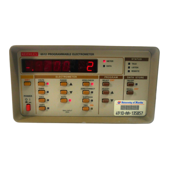
RAM memory is automatically tested as part of the power- up procedure. If a RAM memory error occurs, the “rr” mes- The front panel layout of the Model 6512 is shown in Figure sage will remain on the display. If the instrument was not 2-1. -
Page 23: Figure 2-1 Model 6512 Front Panel
Note that the Model 6512 Note that pressing either of these buttons will cancel will be in this mode when it is first turned on. - Page 24 4 PROGRAM junction with the ZERO CORRECT control to cancel These keys allow access to Model 6512 front panel pro- any offsets within the instrument and is also used as a grams, which control the IEEE-488 primary address, set al- standby mode.
-
Page 25: Display And Indicators
Model 6512 over the IEEE- 488 bus. The Model 6512 has a display made up of a 4 ½ digit signed mantissa as well as a two-digit signed exponent. The expo- nent can be represented either in scientific notation, or with 2.4.3 Tilt bail... -
Page 26: Ieee-488 Address
In the numeric mode, the display might show: lined in Section 7, paragraph 7.4.9. dISP -3 Rear panel familiarization The rear panel of the Model 6512 is shown in Figure 2-2. -
Page 27: Figure 2-2 Model 6512 Rear Panel
SLOWBLOW 15VA MAX 1/8A 90-125V 1/16A 180-250V Figure 2-2 Model 6512 rear panel 1 INPUT 3 IEEE-488 Connector The INPUT connector is a 3-lug female triax connector to be This connector is used to connect the instrument to the IEEE- used for all electrometer signal inputs. -
Page 28: Basic Measurement Techniques
11 EXTERNAL TRIGGER INPUT This BNC connector can be used to apply external trigger pulses to the Model 6512 to trigger the instrument to take one or more readings, depending on the selected trigger mode. -
Page 29: Making Voltage Measurements
CHASSIS CHASSIS GROUND GROUND 100Ω The Model 6512 can be used to measure voltages in the range of ±10µV to ±200V. In principle, the instrument oper- ates much like an ordinary DMM, but its special characteris- A. UNGUARDED B. GUARDED (V, Ω... - Page 30 Thus, to keep the error under 0.1%, the input resistance must be about 1000 times the value of the source resistance, R . Note that the Model 6512 input resistance is ≥ 200G Ω , but the cable resistance appears in parallel. Figure 2-5...
-
Page 31: Guarded Operation
Guarding consists of using a conductor driven by a low-im- pedance source to totally surround the leads carrying a high- impedance signal. The output of this low-impedance source is kept at the same potential as the signal itself, resulting in 6512 PREAMP drastically reduced leakage currents. ( SHIELD) To approach the concept of guarding, let us first review the... -
Page 32: Making Current Measurements
30mA. 2.7.5 Making current measurements NOTE The Model 6512 can resolve currents as low as 0.1fA After measuring high voltage in volts, or A), and measure as high as 20mA in 11 ranges. The following an overload condition in ohms,... -
Page 33: Figure 2-9 Current Measurements
Operation To measure current with the Model 6512, use the following 4. Connect a suitable triax cable to the rear panel INPUT procedure: jack. Connect the other end of the circuit to be measured as shown in Figure 2-9. Shielding will be required for 1. -
Page 34: Making Charge Measurements
With the in- strument on the 2pA range and zero check Note that the Model 6512 voltage burden is typically 1mV or disabled, allow the reading to settle until less. Additional considerations include source resistance and the instrument is within specifications. -
Page 35: Figure 2-11 Coulombs Connections
Use the following procedure to measure charge with the 10-25 count range. Model 6512: 6. Connect the triax cable to the INPUT jack. Connect the other end of the cable to the circuit being measured, as 1. -
Page 36: Resistance Measurements
7. Take the reading from the display. The exponent may be Any such current is integrated along with the input signal placed in either the alpha or numeric modes, as de- and reflected in the final reading. The Model 6512 has a max- scribed in paragraph 2.5. 2-16... -
Page 37: Using The Ohms Function As A Current Source
The Model 6512 ohms function may also be used to generate currents in decade values between 1nA and 100µA. To use These two problems can be minimized by using guarding, the instrument in this manner, simply connect the triax cable especially when measuring resistances above 1GΩ. -
Page 38: Analog Outputs
For example, with a device with an input impedance of 10MΩ, the error due to loading will be approximately 0.1%. The Model 6512 has two analog outputs on the rear panel. The 2V ANALOG OUTPUT provides a scaled 0-2V output with a value of 2V corresponding to full-range input. -
Page 39: Preamp Out
7). Open-circuit voltage of 300V is present at PREAMP OUT in the ohms function. The PREAMP OUT of the Model 6512 follows the signal am- plitude applied to the INPUT terminal. Some possible uses for PREAMP OUT include buffering of the input signal, as well as CAUTION for guarding in the volts and ohms modes. - Page 40 Operation PREAMP OUT INPUT MEASURING DEVICE MODEL 1683 V, Ω GUARD TEST LEAD KIT MODEL 6512 A. CONNECTIONS V OUT = -I IN R F V OUT = V IN I IN PREAMP OUT PREAMP OUT V IN 100Ω 100Ω...
-
Page 41: Using External Feedback
Coulombs 200pC 200mV thoroughly cleaned to maintain the high input imped- ance and low input current of the Model 6512. If these 20nC insulators become contaminated, they can be cleaned with methanol and then dried with clean, pressurized air. *WARNING: Open-circuit voltage of 300V present at PREAMP OUT in ohms. -
Page 42: Shielded Fixture Construction
2.9.3 External feedback procedure 4. The external feedback mode may be cancelled by press- ing one of the four functions keys (VOLTS, OHMS, Use the following procedure to operate the Model 6512 in COUL, or AMPS). the external feedback mode. -
Page 43: Non-Standard Coulombs Ranges
V = kT/q[ln(I/I ) - ln(h /(1 + h tance in farads, and V is the voltage in volts. The Model 6512 display will read charge directly in units determined by the where h is the current gain of the transistor. -
Page 44: Non-Decade Current Gains
Further processing of the current response can be achieved by using the suppress feature. For example, suppress could The Model 6512 electrometer input uses internal decade re- be enabled with a reference input current applied. For all sistance feedback networks for the current ranges. In some subsequent currents, the natural logarithm of the ratio of the applications, non-decade current gains may be desirable. -
Page 45: Using Zero Correct And Baseline Suppression
100MΩ || 22pF (20MΩ, 200MΩ, 100kΩ || 1000pF (µA) ALL GΩ) 100MΩ || 220pF (nA) 100GΩ || 5pF (pA) The Model 6512 has zero correction and baseline suppres- sion modes that allow the cancellation of any internal offsets, C IN C IN 10MΩ... -
Page 46: Data Storage
2. Select a range and function that is consistent with the an- ticipated measurement. The Model 6512 has an internal 100-point data store mode 3. Connect the signal to be suppressed to the instrument input. that can be used to log a series of readings. The fill rate of the data store buffer can be set to specific intervals by a parame-... - Page 47 OFF button when the desired rate appears in the display. memory. You can return to the recall mode at any time to The Model 6512 will then begin storing readings at the review data. selected rate. If you selected the triggered mode, one 9.
-
Page 48: External Triggering
1. Connect the external trigger source to the rear panel BNC EXTERNAL TRIGGER INPUT connector. The The Model 6512 has two BNC connectors on the rear panel shield (outer) part of the connector is connected to digi- associated with instrument triggering. The EXTERNAL tal common. -
Page 49: Meter Complete Output
Model 6512 is to be used in conjunction with a Keithley Model 7001 Switch t Err System to allow the Model 6512 to measure a number of dif- ferent signals, which are to be switched by the scanner. Us- 2.12.2 Meter complete output ing appropriate scanner cards, the Model 7001 can switch up to 80 2-pole channels. -
Page 50: Measurement Considerations
7001 STEP button. The Model 7001 will close the first INSTRUMENT INSTRUMENT INSTRUMENT channel and trigger the Model 6512 to take a reading. When the Model 6512 completes the reading, it will trigger the Model 7001 to go to the next channel. The TYPICAL GROUND LOOP... -
Page 51: Eiectrostatic Interference
2.13.4 Electromagnetic interference (EMI) quickly. However, the high impedance levels of many Model 6512 Electrometer measurements do not allow these charges The electromagnetic interference characteristics of the Mod- to decay rapidly, and erroneous or unstable readings may re- el 6512 Electrometer comply with the electromagnetic com- sult. -
Page 52: Input Capacitance Effects
As an example, assume that the Model 6512 is being used to measure the value of a high-impedance voltage source, as shown in Figure 2-26. The source and source resistance are... -
Page 53: Source Resistance
Operation Because of the charging of C , the electrometer follows the Thus, if R has a value of 10MΩ, and C has a value of exponential curve shown in Figure 2-26B. At the end of one 100pF, the half-power point will be 159Hz. time constant (R ), the voltage will reach approximately 63% of its final value. -
Page 54: Source Capacitance
10,000pF is leak- age measurement of capacitors. In this case, Input E NOISE In amps, the Model 6512 is designed to accommodate up to must include the effects of the voltage source (E ) used to 10,000pF input capacitance (C in Figure 2-27). - Page 55 Operation Table 2-12 Engineering units conversion Symbol Prefix Exponent femto- pico- nano- µ micro- milli- kilo- mega- giga- 2-35...
-
Page 56: Ieee-488 Programming
This section contains detailed information on programming retained within an internal command buffer for execution at Model 6512 operating modes over the IEEE-488 bus. For ad- the time the X character is received. If any errors occur, the ditional bus information, refer to the following sections of... - Page 57 Some examples of valid command strings include: Device-dependent command summary Single command string. Device-dependent commands that control the Model 6512 F0K1R0X Multiple command string. are listed in Table 3-2. These commands are covered in detail T6 X Spaces are ignored.
- Page 58 IEEE-488 Programming Table 3-2 Device-dependent command summary Mode Command Description Paragraph Calibration A+nnn.nn Calibrate Function and Range 3.2.1 Value An.nnnE+n Reading Electrometer 3.2.2 Mode Buffer Reading Maximum Reading Minimum Reading Zero Check Zero Check Off 3.2.3 Zero Check On Function Volts 3.2.4 Amps...
- Page 59 IEEE-488 Programming Table 3-2 Device-dependent command summary (cont.) Mode Command Description Paragraph External Range 3.2.11 Volts Amps Ohms Coul. Feedback Auto Auto Auto Auto Auto 2k Ω 200mV 200pC 200mV 20k Ω 20pA 200k Ω 200pA 20nC 2M Ω 200V 20nC 20M Ω...
-
Page 60: Calibration Value (A)
An.nnnE+n Description One advanced feature of the Model 6512 is its digital calibration capabilities. Instead of the more difficult method of adjusting a number of potentiometers, the user need only apply an ap- propriate calibration signal and send the calibration value over the bus. -
Page 61: Zero Check (C)
The function command and its options allow you to select the type of measurement made by the Model 6512, and they perform essentially the same operations as the front panel function keys. The parameter options associated with the function command set the instrument to measure voltage, current, resistance, charge, or external feedback. -
Page 62: Data Format (G)
IEEE-488 Programming 3.2.5 Data format (G) Purpose To control the format of the data the instrument sends over the IEEE-488 bus. Format Reading with prefix (NDCV-1.23456E+00) Reading without prefix (-1.23456E+00) Reading with prefix and suffix (NDCV-1.23456E+00,001) Default Upon power-up, or after a DCL or SDC command, the instrument will be in the G0 (reading with prefix) mode. -
Page 63: Eoi And Bus Hold-Off Modes (K)
Keep in mind that all bus operation will cease–not just activity associated with the Model 6512. The advantage of this mode is that no bus commands will be missed while the instrument is processing commands previously received. -
Page 64: Non-Volatile Memory Storage (L)
SRQ. Once an SRQ is gener- ated, the status byte can be checked to determine if the Model 6512 was the instrument that as- serted SRQ, and, if so, what conditions caused it to do so. Note that additional data and error conditions can be checked by using the U1 and U2 commands, as described in paragraph 3.2.13. - Page 65 Bits 2 and 7 are not used, and are always set to 0. Bit 6 provides a means for you to determine if SRQ was asserted by the Model 6512. If this bit is set, service was requested by the instrument. Bit 5 flags a Model 6512 error condition, which can be further checked with the U1 command.
- Page 66 IEEE-488 Programming An illegal device dependent command (IDDC) or illegal device dependent command op- tion (IDDCO) was transmitted. The instrument was programmed when not in remote. A trigger overrun has occurred (the instrument was triggered while processing a reading from a previous trigger). A number error has occurred (a calibration value was out of limits).
-
Page 67: Baseline Suppression (N)
IEEE-488 Programming 3.2.9 Baseline suppression (N) Purpose To enable or disable baseline suppression. Format Disable suppression Enable suppression Default Upon power-up, or after receiving a DCL or SDC command, suppression will be disabled (N0). Description The baseline suppression mode allows a stored offset value to be subtracted from subsequent readings. -
Page 68: Data Store Mode (Q)
The data store commands enter the data storage mode and allow you to store up to 100 readings within the internal memory of the Model 6512. By entering an appropriate parameter, readings may be stored at one of six intervals between the conversion rate and one reading per hour. Either during or after the storage process, readings, including maximum and minimum values, may be recalled by using the B command as described in paragraph 3.2.2. -
Page 69: Range (R)
IEEE-488 Programming 3.2.11 Range (R) Purpose To select the measurement range. Format Volts Amps Ohms Coul. External Feedback ________________________________________________________ Auto Auto Auto Auto Auto 200mV 2kΩ 200pC 200mV 20pA 20kΩ 200pA 200kΩ 20nC 200V 2MΩ 20nC 200V 20nA 20MΩ 20nC 200V 200nA 200MΩ... -
Page 70: Trigger Mode (T)
The trigger modes are paired according to the type of stimulus that is used to trigger the instru- ment. In the T0 and T1 modes, triggering is performed by addressing the Model 6512 to talk. In the T2 and T3 modes, the IEEE-488 multiline GET command performs the trigger function. The... -
Page 71: Status (U)
IEEE-488 Programming 3.2.13 Status (U) Purpose To request status, error, and data conditions from the instrument. Format Send status word Send instrument error conditions Send instrument data conditions Description The status commands allow access to information concerning instrument operating modes that are controlled by other device-dependent commands such as F (function) and R (range). - Page 72 IEEE-488 Programming DEFAULT: 6512 F YY <CR LF> TERMINATOR MODEL NUMBER PREFIX ASCII = : CR LF FUNCTION : = LF CR 0=VOLTS 1=AMPS EOI; BUS HOLD-OFF 2=OHMS 0 = 1 EOI + HOLD-OFF 3=COULOMBS 1 = NO EOI + HOLD-OFF...
- Page 73 CRT. Error The U1 command allows access to Model 6512 error conditions in a similar manner. Once the sequence Conditions U1X is sent, the instrument will transmit the error conditions with the format shown in Figure 3-4 the next time it is addressed to talk in the normal manner.
- Page 74 U1 error word, the U2 word is made up of ASCII characters representing binary values. Unlike the U1 error word, however, the U2 data condition word will not be cleared when read; thus, instrument status in the U2 word is always current. 6512 0000 <CR LF>...
-
Page 75: Terminator (Y)
IEEE-488 Programming 3.2.14 Terminator (Y) Purpose To program the terminator character(s) the Model 6512 adds to the end of its reading and status strings. Format Y<LF> <CR> <LF> <CR> (two terminator characters) Y<CR> <LF> <CR> <LF> (two terminator characters) Y<ASCII>... -
Page 76: Zero Correct (Z)
IEEE-488 Programming 3.2.16 Zero correct (Z) Purpose To zero correct the instrument, nulling any internal offsets that might affect accuracy. Format Zero correct off Zero correct on Default Upon power-up, or after receiving a DCL or SDC command, zero correct will be disabled (Z0). Description The zero correct and zero check commands work together to cancel any internal offsets that might upset accuracy. -
Page 77: Bus Connections
Bus connections Connect the Model 6512 to the cable as follows: The Model 6512 is to be connected to the IEEE-488 bus 1. With the power off, line up the connector on the cable through a cable equipped with standard IEEE-488 connec- with the connector on the rear panel of the instrument. -
Page 78: Talk-Only Mode
2. Press the PROGRAM SELECT button until the IEEE program message is displayed, and then release the but- The Model 6512 may be placed into the talk-only mode and ton. Select the desired IEEE-488 talk-only parameter be used with a listen-only device such as a printer. When in (40 or 41) using an ADJUST button. -
Page 79: Bus Error
IEEE-488 Programming 3.6.1 Bus error 3.6.3 Trigger overrun error A bus error will occur if the instrument receives a device-de- A trigger overrun error occurs when the instrument receives pendent command when it is not in remote, or if an illegal de- a trigger while it is still processing a reading from a previous vice-dependent command (IDDC) or illegal device- trigger. -
Page 80: Applications
For example, the typical input resistance for an ordinary ue of 10V. DMM is on the order of 10M Ω . In contrast, the Model 6512 has an input resistance of greater than 200T Ω (2 × 10 Ω ). - Page 81 Applications TRIAX CABLE UNDER TEST INPUT SHIELDED VΩ, GUARD TEST FIXTURE MODEL 6512 COMMON OUTPUT MODEL 230 VOLTAGE SOURCE A. CONNECTIONS 6512 PREAMP TEST FIXTURE A/D CONVERTER COMMON 230 VOLTAGE SOURCE OUTPUT B. EQUIVALENT CIRCUIT Figure 4-1 Leakage current measurement...
-
Page 82: Diode Characterization
Applications Diode characterization *R = displayed resistance. When the Model 6512 is placed in the ohms mode, constant current values between 1nA and 100µA are available at the IN- Figure 4-2 shows the basic circuit configuration for using the PUT jack high and low terminals, as shown in Table 4-1. (Input Model 6512 in this manner. -
Page 83: Capacitor Leakage Measurements
However, values under 10k Ω are not recommended. (Refer to paragraph 2.13.8.) At the start of the test, the Model 6512 should be placed in the amps mode and on the 20mA range. The Model 230 Volt-... -
Page 84: Capacitance Measurement
Fig- At the moderate impedance levels of many circuits, insula- ure 4-5. Since charge is to be measured, the Model 6512 tion resistance is seldom a consideration, as it is generally... -
Page 85: Guarded Resistance Measurements
With the constant-current method discussed above, the Mod- as shown in Figure 4-7. In this case, the rear panel V, Ω el 6512 can make measurements as high as 200G Ω . Howev- GUARD switch is used to apply a guard signal to the inner er, the insulation resistance of such materials as polyethylene shield of the connecting triax cable. - Page 86 Insulation resistance measurement (guarded) Since the Model 230 voltage source can be adjusted over a A typical configuration for using the Model 6512 to make wide range of values (up to ±101V), this configuration can be V/I resistance measurements is shown in Figure 4-8. Here, used for voltage coefficient studies, as described later in this...
- Page 87 Applications TRIAX CABLE INPUT UNKNOWN RESISTANCE V, Ω GUARD SHIELDED TEST FIXTURE MODEL 6512 OUTPUT COMMON MODEL 230 VOLTAGE SOURCE A. CONNECTIONS 6512 PREAMP TEST FIXTURE A/D CONVERTER COMMON 230 VOLTAGE SOURCE OUTPUT B. EQUIVALENT CIRCUIT Figure 4-7 Insulation resistance measurement using external voltage source...
-
Page 88: High-Impedance Voltmeter
Such a large error would not be tolerable in this case because of the 1% accuracy requirement. However, since the Model The input resistance of the Model 6512 in the volts mode is 6512 has an input resistance of 200TΩ, its error in this exam- greater than 200TΩ. - Page 89 TRIAX CABLE HIGH MEGOHM INPUT RESISTOR V, Ω GUARD SHIELDED TEST FIXTURE MODEL 6512 COMMON OUTPUT MODEL 230 VOLTAGE SOURCE A. CONNECTIONS 6512 PREAMP TEST FIXTURE HIGH MEGOHM RESISTOR...
-
Page 90: Static Charge Detection
Applications Static charge detection To perform the test, connect the Model 6512 to the Faraday cup using a suitable shielded cable, such as Model 4801 Electrostatic charge is a deficiency or excess of electrons on BNC cable. A Model 7078-TRX-BNC triax-to- BNC adapter an ungrounded surface. -
Page 91: Performance Verification
Initial conditions The procedures outlined in this section may be used to verify The Model 6512 must be turned on and allowed to warm up that the instrument is operating within the limits stated in the for at least two hours before beginning the verification pro- specifications at the front of this manual. -
Page 92: Verification Procedures
5.5.2 Amps verification you to dangerous voltages. Use standard Connect the Model 6512 to the Model 263, as shown in Fig- safety precautions when such danger- ous voltages are encountered. ure 5-1, and perform amps verification as follows: 1. -
Page 93: Coulombs Verification
* Reading limits shown include Model 6512 and Model 263 accuracy specifications. 5.5.3 Coulombs verification Connect the Model 6512 to the Model 263 as shown in Figure 5-1, and perform coulombs verification as follows: 4. Program the Model 263 to output 1.90000nC, and press OPERATE to source charge to the Model 6512. - Page 94 Performance Verification 10. Enable zero check on the Model 263, and turn off the external calibration (190V) source.
-
Page 95: Ohms Verification
200V 190.000V 189.86 to 190.14V * The 200mV, 2V, and 20V ranges allowable readings include Model 263 error. The 200V range reading is based solely on Model 6512 accuracy specifica- tions. 5.5.5 Ohms verification Connect the Model 6512 to the Model 263, as shown in Figure 5-3, and perform ohms verification as follows: NOTE Charge and current verification must be performed before resistance verification. - Page 96 Note that guard must be enabled on both the Models 6512 and 263 when verifying the G Ω rang- es. Also, note that COM of the Model 6512 must be con- nected to COMMON of the Model 263 (see Figure 5-3).
- Page 97 Figure 5-3 COMMON Connections for ohms verification OUTPUT MODEL 263 Table 5-3 Limits for ohms verification Calculated limit 6512 263 output 6512 & 263 Equipment Allowable 6512 reading range (nominal) guard 263 reading error* Limit (1 year, 18°-28°C) 2k Ω...
-
Page 98: Input Impedance Verification
1. Connect the DC calibrator, Model 263, and the Model 6512 together as shown in Figure 5-4. 2. Place the Model 6512 in the volts function, select the 20V range, and enable ZERO CHECK. Verify that the display shows 0.000V ±1 count. If not, enable ZERO CORRECT. -
Page 99: Theory Of Operation
This section contains an overall functional description of the offset current (less than 5fA). The output stage provides fur- Model 6512 in block diagram form, as well as details of the ther amplification, thus allowing the preamp output to go as various sections of the instrument. -
Page 100: Input Preamplifier
Theory of Operation ANALOG FEEDBACK ELEMENTS, SWITCHES INPUT OUTPUT RANGING STAGE STAGE AMPLIFIER CONVERTER µP DISPLAY ANALOG DIGITAL ±5 ±210 ±24 -9.1 FRONT POWER SUPPLY IEEE-488 PANEL INTERFACE BUTTONS DIGITAL Figure 6-1 Overall block diagram Input preamplifier FEEDBACK SWITCHING The input preamplifier provides the high input impedance and high output voltage capability necessary for the volts and ohms functions, and the low input impedance and high current output capability needed for the amps and coulombs functions. -
Page 101: Input Stage
Theory of Operation 6.3.1 Input stage The exact configuration of the input preamplifier will depend on the measuring function. Figure 6-3 shows circuit config- A simplified schematic of the input stage is shown in Figure uration for the four measuring functions. In the volts func- tion, the circuit is set up as a high-input impedance (2 ×... -
Page 102: Gain Stage
Theory of Operation Q303, Q304, and Q305) are used in this configuration. Each +0.4V (BOOTSTRAPPED) transistor pair is used for one-half the output voltage swing. Q308 R314 Q301 and Q304 are used for the positive half, while Q303 BOOTSTRAPPED INPUT and Q305 are used for the negative half. -
Page 103: Ohms Voltage Source
Theory of Operation sistors. This input causes a current, V/R , to flow through tory to provide an accurate 10V output. The actual source R309 and R323. This current develops an output voltage: output is 10V, but this value is divided to 1V and 0.1V by a -V(R ). -
Page 104: Additional Signal Conditioning
Z IN = 10MΩ || Z F The multiplexer selects among the three signals that are part of Figure 6-10 the Model 6512 measurement cycle. During the common phase, Zero check configuration in amps and coulombs the multiplexer selects signal common. During the reference phase, the -2V reference voltage is selected, while the signal from the ranging amplifier is selected during the signal phase. -
Page 105: 2V Reference Source
Figure 6-14 -2V reference source CALCULATE A READING A/D converter The Model 6512 uses an A/D converter that utilizes both constant-frequency charge balance and single-slope tech- COMMON PHASE niques. This combination gives the instrument both high ac- curacy and relatively fast conversion times. - Page 106 Theory of Operation SINGLE SLOPE U136B R149H I SS ENABLE/DISABLE U138A C128 Q108 R153G SINGLE SLOPE COMPARATOR BUFFER U138B R153H U137A LEVEL SHIFT INTEGRATOR CHARGE BALANCE CURRENT COMPARATOR U136C R149A U211C +1.5V R138 U137B TO MPU U126A I CB U135C U135B CR113 U210B...
-
Page 107: Digital Circuitry
DS terminal to act as a system clock. 6.6.2 Memory elements 6.6.4 IEEE-488 bus Firmware for the Model 6512 is stored in U106, a 27128 16K × 8 PROM. Temporary storage is afforded by U107, a 6116 The Model 6512 has a standard IEEE-488 interface that al- 2K ×... -
Page 108: Input/Output Circuitry
6512-116 located at the end of Section 8. At the end of its conversion cycle, the Model 6512 sends a pulse out the Meter Complete Output jack on the rear panel. -
Page 109: Power Supplies
6512-106, and VR303 regulates the output voltage. Both of these sup- page 1 and 6512-166 located at the end of Section 8. plies are referenced to analog and signal common. The power supplies are essentially divided into two groups: The ±5V sources supply power to much of the input pream-... -
Page 110: Maintenance
5. Replace the top cover, and connect the instrument to the Line voltage selection power line. The Model 6512 may be operated from either 105-125V or Table 7-1 210-250V, 50 or 60Hz power sources. A special transformer Line voltage selection (50-60Hz) may be installed for 90-110V and 195- 235V ranges. -
Page 111: Line Fuse Replacement
A rear panel fuse protects the power line input of the instru- Calibration ment. Use the following procedure to replace the line fuse: An advanced feature of the Model 6512 is its digital calibra- WARNING tion capabilities. Instead of the more conventional time-con-... -
Page 112: Required Calibration Equipment
Calibration should be performed under laboratory conditions ENABLED having an ambient temperature of 23° ±1°C and a relative humidity of less than 70%. Both the Models 6512 and 263 DISABLED should be allowed to warm up for at least two hours before beginning calibration. -
Page 113: Input Current Adjustment
Once these ranges are calibrated, the remaining ranges are move it from the instrument. automatically calibrated. Use the AMPS (active) function of 3. Place the Model 6512 in the amps function, and select the Model 263 to source current. the 2pA range. -
Page 114: Coulombs Calibration
ZERO on the Model 263. 6. Adjust the display of the Model 6512 for a reading of 9. On the Model 6512, disable zero correct and suppress. 19.000nC using the ADJUST buttons of the Model 6512. -
Page 115: Volts Calibration
Proceed as follows: Model 263 to output the external voltage source by pressing SHIFT VOLTS. 1. Connect the Model 263 to the Model 6512, as shown in Figure 7-3. 15. Adjust the display of the Model 6512 to read 190.00V using the ADJUST buttons of the Model 6512. -
Page 116: Ohms Calibration
Digitally calibrating the Model 6512 over the IEEE-488 bus requires the use of a calibration program, which is listed in Appendix D (paragraph D.9). * Set Model 6512 reading to exact resistance displayed on Model 263 using Model 6512 ADJUST keys. NOTE 10. -
Page 117: Additional Calibration Points
IEEE-488 bus (The 1. With the power off, connect the Models 263 and 6512 to flashing exponent decimal points will indicate parameters the GPIB interface of the computer. -
Page 118: Disassembly Instructions
Maintenance NOTE A. Remove the four screws that secure the top shield to the electrometer board. In order to avoid damage, assume that all B. Carefully lift the shield clear of the board. parts are static sensitive. C. Disconnect the input wires from the electrometer board. - Page 119 Maintenance Figure 7-5 Exploded view 7-10...
-
Page 120: Troubleshooting
The self-diagnostic program can be used to test the front pan- Success in troubleshooting complex equipment like the Model 6512 depends not only on the skill of the technician, el LEDs, access the firmware revision level, and enter a spe- cial mode to allow signal tracing through the instrument. -
Page 121: Power Supply Checks
Maintenance 7.7.4 Power supply checks 5. At this point, the instrument will enter the diagnostic mode that switches the instrument among the zero All power supply voltages should be checked first to make (common), calibration (reference), and signal phases of sure they are within the required limits. - Page 122 Maintenance Table 7-8 Power supply checks Step Item/component Required condition Remarks S102 Line Switch Set to 115 or 230 as required. Line voltage selection. F101 Line Fuse Check for continuity. Remove fuse to check. Line power Plugged into live receptacle; power on. +5V Digital Supply 5V, ±5% Referenced to digital common.
-
Page 123: Ranging Amplifier Gain Configuration
Maintenance X = Relay Energized. * = These relays may also be energized de- For example, with the instrument on the 20V range, an input pending on range and function. signal of 19V could be applied. Assuming the input amplifier is operating properly, the voltage seen at the PREAMP OUT 7.7.6 Ranging amplifier gain configuration should also be 19V. - Page 124 Maintenance Table 7-11 A/D converter checks Step Item/component Required condition Remarks Turn on power, select 2V range, and short input. All A/D checks referenced to analog common. U127, pin 10 1.2288MHz gated clock A/D clock. U127, pin 7 307.2kHz gated clock A/D synchronous clock.
- Page 125 Maintenance Table 7-13 Ranging amplifier checks Step Item/component Required condition Remarks Range Power-on, 200V DC range, zero check off Measure between 2V ANALOG OUTPUT and COM. Apply 190V DC to input 1.9V Check X0.01 gain. Range Select 20V DC range Apply 19V DC to input 1.9V Check X0.1 gain.
-
Page 126: Input Stage Balancing Procedure
W303 in position B. or other foreign matter. In particular, there are two areas within the Model 6512 that have numerous high impedance Proceed as follows: nodes where contamination could cause degraded perfor- 1. -
Page 127: Replaceable Parts
Parts list If the instrument is to be returned to the factory for service, Parts for the Model 6512 are listed in tables integrated with carefully pack the unit and include the following: the schematic diagrams and component layout drawings on the following pages. - Page 128 Model 6512 Digital Board, Parts List KEITHLEY CIRCUIT DESIG. DESCRIPTION PART NO. C101 CAP,4700UF,-20,+100%,16V,ALUMINUM C-313-4700 C102,112,116-118,123, 125-127 CAP,.1UF,20%,50V,CERAMIC C-237-.1 C104,134 C105,113 CAP, 10UF,-20+100%,25V,ALUM ELEC C-314-10 C106 CAP,1UF,20%,50V, CERAMIC C-237-1 C107,111 CAP,10UF,20%,20V,TANTALUM C-179-10 C119,124 CAP,22PF,10%,1000V,CERAMIC C-64-22P C120 CAP, 0.1UF, 20%, 100V, POLYESTER C-305-.1...
- Page 129 Model 6512 Digital Board, Parts List (cont.) KEITHLEY CIRCUIT DESIG. DESCRIPTION PART NO. U117,128 IC,QUAD 2 INPUT NOR,74HC02 IC-412 U118,135 IC, TRIPLE 3 INPUT NAND, 74HC10 IC-341 U119 IC,OCTAL INTERFACE BUS TRANSCEIVER,75161 IC-299 U120 IC,OCTAL INTERFACE BUS,75160 IC-298 U121,122 IC,OPTOCOUPLER,2601...
- Page 130 Model 6512 Display Board, Parts List KEITHLEY CIRCUIT DESIG. DESCRIPTION PART NO. C201 CAP,10UF,20%,20V,TANTALUM C-179-10 DS-201 DD-31 SELECTION 617-603 DS202-205 DD-30 SELECTION 617-604 DS206 DIGITAL DISPLAY (DOUBLE DIGIT) DD-39 DS208-213,215-219,221,223,224 PILOT LIGHT,RED,LED PL-71 DS214 PILOT LIGHT, YELLOW,LED PL-72 P1016 CABLE ASSEMBLY, 24 CONDUCTOR...
- Page 132 Model 6512 Electrometer Board, Parts List KEITHLEY CIRCUIT DESIG. DESCRIPTION PART NO. C301,302 CAPACITOR, ELECTROLYTIC C-240-4.7 C303,304 CAPACITOR, ELECTROLYTIC C-240-10 C305 CAP,1500UF,-20,+100%,25V,ALUM ELEC C-314-1500 C306 CAP, 470UF, -20+100%, 16V ALUMINUM C-313-470 C307 CAP, .001PF, 2.5%, 630V POLYESTER C-252-.001 C308 CAP,10PF,10%,1000V,CERAMIC...
- Page 133 Model 6512 Electrometer Board, Parts List (cont.) KEITHLEY CIRCUIT DESIG. DESCRIPTION PART NO. R349 RES,5.6K,5%,1/4W,COMPOSITION OR FILM R-76-5.6K R350 RES, 150K, 5%, 1/4W COMPOSITION OR FILM R-76-150K R351 RES, 16.5K, 1%, 1/8W METAL FILM R-88-16.5K R352 RES, 24.9K, 1%, 1/8W, METAL FILM R-88-24.9K...
- Page 134 Model 6512 Mechanical, Parts List DESCRIPTION KEITHLEY PART NO. SHIELD, BOTTOM 617-314 SOLDER LUG LU-7 CONNECTOR, BNC CS-520 PUSHBUTTON 228-317-4 PUSHBUTTON 228-317-6B SHIELD, BOTTOM COVER 617-305B SHIELD, INPUT TUBE 30472 BINDING POST, RED BP-11-2 CAP, PROTECTIVE CAP-30-1 CAP,1000PF,10%,1000V,CERAMIC C-64-1000P PUSHBUTTON...
-
Page 135: Bus Overview
IEEE-488 Bus Overview Introduction TO OTHER DEVICES This appendix provides an overview of the IEEE-488 bus. For detailed Model 6512 programming information, refer to Section 3. DEVICE 1 ABLE TO TALK, LISTEN AND CONTROL (COMPUTER) Bus description DATA BUS The IEEE-488 bus, which is also frequently referred to as the... - Page 136 60 . Note, however, that many devices, they require service from the controller. including the Model 6512, do not use secondary addressing. Once the device is properly addressed, appropriate bus trans- Handshake lines actions are set to take place. For example, if an instrument is...
- Page 137 IEEE-488 Bus Overview NRFD (Not Ready For Data)—The acceptor controls the Once all NDAC and NRFD are properly set, the source sets state of NRFD. It is used to signal to the transmitting device DAV low, indicating to accepting devices that the byte on the to hold off the byte transfer sequence.
- Page 138 Removes all listeners from bus. (Untalk) Removes talker from bus. Device-dependent* Programs Model 6512 operating modes. * See Section 3 for a complete description of device-dependent commands. Uniline commands SRQ (Service Request)—SRQ is asserted by a device when it requires service from a controller.
- Page 139 For example, the command is generally the last command in the serial polling sequence. sequence F0X is used to place the Model 6512 in the volts mode. The IEEE-488 bus actually treats these commands as data in that ATN is false when the commands are transmitted.
- Page 140 IEEE-488 Bus Overview Figure A-3 Command groups...
-
Page 141: General Bus Commands
REN (Remote Enable) General bus commands are those commands such as DCL The remote enable command is sent to the Model 6512 by (Device Clear) that have the same general meaning regard- the controller to set up the instrument for remote operation. - Page 142 GET (Group Execute Trigger) The DCL command may be used to clear the Model 6512 GET may be used to trigger the Model 6512 to take readings if and return the unit to its power-up default conditions. Note the instrument is placed in one of the two GET trigger modes.
-
Page 143: Interface Function Codes
Open-collector Bus Drivers RL (Remote-Local Function)—The RL function defines the No Extended Talker Capabilities ability of the Model 6512 to be placed in the remote or local No Extended Listener Capabilities modes. PP (Parallel Poll Function)—The Model 6512 does not have... - Page 144 DT (Device Trigger Function)—The ability for the Model LE (Extended Listener Function)—The Model 6512 does 6512 to have its readings triggered is provided by the DT not have extended listener capabilities. function. E (Bus Driver Type)—The Model 6512 has open-collector C (Controller Function)—The Model 6512 does not have...
-
Page 145: Example Programs
IEEE-488 cable for bus connections. The following computer hardware is required to run the ex- 2. Make sure the Model 6512 is set for a primary address ample programs: of 27. You can check or change the address as follows: A. - Page 146 Program 1. Basic input/output program ' Program to send commands and read data from Model 6512. OPEN "IEEE" FOR OUTPUT AS #1 ' Open IEEE-488 output path.
- Page 147 Program 2 below demonstrates basic data store operation readings. over the bus. The program sets up the Model 6512 for SRQ on data store full, and it then enables data store at the conver- Program 2. Example data store program ' Program to use Model 6512 data store feature.
- Page 148 (K5) is sent to generate the error. The U1 error word is re- Program 3. SRQ and status byte program ' Program to demonstrate Model 6512 SRQ and status byte. OPEN "IEEE" FOR OUTPUT AS #1 ' Open IEEE-488 output path.
- Page 149 Program 4. Status word program ' Program to obtain status words from Model 6512. OPEN "IEEE" FOR OUTPUT AS #1 ' Open IEEE-488 output path. OPEN "IEEE" FOR INPUT AS #2 ' Open IEEE-488 input path.
- Page 150 7. After all functions are calibrated, the program will prompt for permanent storage of calibration constants in 1. With the power off, connect the Models 263 and 6512 to NVRAM. This feature allows you to stop at this point in the GPIB interface of the computer.
- Page 151 ' Put 263, 6512 in remote. PRINT #1, "CLEAR" ' Send DCL. PRINT "Connect 263 to 6512 input and external voltage source." PRINT "See Figures 7-3 and 7-4 in Section 7 of manual." PRINT "Set external voltage source to output 190.00V to 263."...
- Page 152 PRINT "All volts ranges calibrated." PRINT #1, "OUTPUT 8;F0R8W1G1X" ' 263: 10G ohm range, guard on. BEEP: PRINT "Set 6512 GUARD switch to ON, press a key to continue." SLEEP PRINT "Continuing..." FOR I = 8 TO 2 STEP -1...
-
Page 153: Model 617/6512 Software Compatibility
Model 6512 fy bit positions, you will have to make program adjustments for a Model 617 in a system application and make the neces- to accommodate the new string lengths. - Page 154 Index 2V analog output 2-8, 2-18 Charge measurement considerations 2-17 -2V reference source 6-7 Chassis ground 2-8 Electrometer 2-3 Command codes A-5 Electrometer commands 3-1 COM terminal 2-8 Electrometer input circuitry 2-21 Component layout drawings and sche- EIectrostatic interference 2-31 matic diagrams 8-1 Engineering units conversion 2-35 Computer hardware requirements D-1...
- Page 155 Meter complete output 2-29 IDDCO error 3-24 METER and DATA indicators 2-5 IEEE-488 address 2-6 Microcomputer 6-9 IEEE-488 bus 6-10 Model 617/6512 software compati- IEEE-488 bus digital calibration 7-8 Quick start procedure 1-3 bility E-1 IEEE-488 bus lines A-2 Multiple commands 3-1...
- Page 156 Specifications 1-2 Triggering example 2-30 Verification procedures 5-2 SRQ mask 3-9 Troubleshooting 7-11 V/I resistance measurements with ex- SRQ mask (M) and status byte format ternal voltage source 4-8 Voltage coefficients of high-megohm SRQ and status byte program D-4 resistors 4-10 Static charge detection 4-11 Voltage measurement considerations 2-10 Status byte 3-10...
Need help?
Do you have a question about the 6512 and is the answer not in the manual?
Questions and answers