Table of Contents
Advertisement
Quick Links
Download this manual
See also:
Instruction Manual
Advertisement
Table of Contents

Subscribe to Our Youtube Channel
Related Manuals for Keithley 6514


Summary of Contents for Keithley 6514
- Page 1 Model 6514 System Electrometer Quick Results Guide A G R E A T E R M E A S U R E O F C O N F I D E N C E...
- Page 2 WARRANTY Keithley Instruments, Inc. warrants this product to be free from defects in material and workmanship for a period of 1 year from date of shipment. Keithley Instruments, Inc. warrants the following items for 90 days from the date of shipment: probes, cables, rechargeable batteries, diskettes, and documentation.
- Page 3 Model 6514 System Electrometer Quick Results Guide ©2003, Keithley Instruments, Inc. All rights reserved. Cleveland, Ohio, U.S.A. First Printing, May 2003 Document Number: 6514-903-01 Rev. A...
- Page 4 Revision includes a revised copy of this print history page. Revision A (Document Number 6514-903-01) ..............August 2003 All Keithley product names are trademarks or registered trademarks of Keithley Instruments, Inc. Other brand names are trademarks or registered trademarks of their respective holders.
- Page 5 Keithley products are designed for use with electrical signals that are rated Measurement Category I and Measurement Category II, as described in the International Electrotechnical Commission (IEC) Standard IEC 60664. Most measurement, control, and data I/O signals are Measurement Category I and must not be directly connected to mains voltage or to voltage sources with high transient over-voltages.
- Page 6 To maintain protection from electric shock and fire, replacement components in mains circuits, including the power transformer, test leads, and input jacks, must be purchased from Keithley Instruments. Standard fuses, with applicable national safety ap- provals, may be used if the rating and type are the same. Other components that are not safety related may be purchased from other suppliers as long as they are equivalent to the original component.
-
Page 7: Table Of Contents
Table of Contents Introduction ................... 1 Measurement capabilities .............. 1 Front and rear panels ..............2 Basic connections ................3 Input connector ..............3 Low noise input cables ............3 Basic connections to DUT ............. 4 Basic operation ................6 Selecting operating modes ............. - Page 8 List of Illustrations Quick Results Guide Figure 1-1 Front panel ................2 Figure 1-2 Rear panel ................. 2 Figure 1-3 Input connector ................. 4 Figure 1-4 Basic connections for unguarded measurements ................4 Figure 1-5 Basic connections for guarded measurements ......5...
- Page 9 List of Tables Quick Results Guide Table 1-1 Volts and ohms measurement procedure ........6 Table 1-2 Amps measurement procedure ..........7 Table 1-3 Charge measurement procedure ..........7 Table 1-4 SCPI commands for basic measurements ......... 9 Table 1-5 Command sequence for volts measurement example ....
-
Page 10: Introduction
Most commands have a query form. For example, FUNC ‘VOLT’ selects the voltage measurement function, while :FUNC? requests the present measurement function. Note that the Model 6514 must be addressed to talk after sending a query command. For operations where command sequence is important, programming examples are provided. -
Page 11: Front And Rear Panels
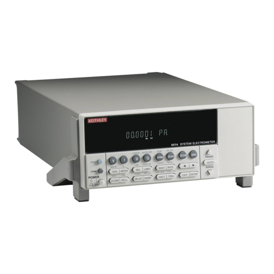
Model 6514 Quick Results Guide Front and rear panels The front and rear panels of the Model 6514 are shown in Figures 1 and 2. The use of the various instrument controls and connectors will be explained throughout this guide. -
Page 12: Basic Connections
• Model 237-ALG-2 — This 2-meter low noise triax cable mates directly to the input connector of Model 6514 and is terminated with alligator clips on the other end. Model 7078-TRX-x cables — These low noise triax cables are terminated with •... -
Page 13: Basic Connections To Dut
Model 6514 Quick Results Guide Figure 3 Input connector Input High Input Low Chassis Ground INPUT 250V PEAK Volts, Amps, Ohms & Coulombs A. Unguarded (GRD off) Input High 0.1Ω Guard Fuse Chassis COMMON Ground Input Low INPUT 250V PEAK Volts and Ohms only B. - Page 14 Model 6514 Quick Results Guide Guarded connections The basic guarded connections for volts and ohms are shown in Figure 5. With guard (GRD) on, the driven guard is available at the inner shell of the triax connector which is connected to the metal guard plate. The driven guard is used to eliminate leakage current and capacitance in high impedance circuits that could corrupt the volts or ohms measurement.
-
Page 15: Basic Operation
3. Enable or disable guard. Use the GRD key to select depending on guarded or unguarded connections. 4. Perform zero correct (volts only). Press ZCOR to zero correct 6514 for maximum volts accuracy. 5. Select range. Use RANGE keys to manually select range. -
Page 16: Making Amps Measurements
Press ZCHK to enable zero check before making connection changes or selecting function. 2. Select amps function. Press I to measure current. 3. Perform zero correct. Press ZCOR to zero correct 6514 for maximum accuracy. 4. Select range. Use RANGE keys to manually select range. -
Page 17: Measurement Considerations
The :READ? command is typically used to trigger a reading and request the data string. The data string is sent to the computer when the Model 6514 is addressed to talk. The data string can be made of up to three elements separated by commas. The first element is the voltage, current, resistance, or charge reading, the second is the timestamp, and the third is status. - Page 18 Select volts measurement function. SENS:VOLT:RANG 20 Select 20V range. SENS:VOLT:GUAR ON Enable guard mode. SYST:ZCH OFF Disable zero check. READ? Trigger and acquire one voltage reading. *Model 6514 must be addressed to talk after sending :READ? to trigger and acquire data.
-
Page 19: Settings To Optimize Performance
Disable zero check. READ? Trigger and acquire one current reading. *Model 6514 must be addressed to talk after sending :READ? to trigger and acquire data. Settings to optimize performance Range To achieve best accuracy, the Model 6514 should be on the lowest possible measurement range. -
Page 20: Rate
4 -digit resolution. Select the FAST rate if speed is of primary importance (at the expense of increased reading noise). Digits The DIGIT key sets display resolution for Model 6514. Display resolution can be set from to 6 digits. This single global setting affects display resolution for all measurement functions. -
Page 21: Rel Key
Model 6514 Quick Results Guide With both filters enabled, the median filter operation is performed first. After the median filter yields a reading, it is sent to the stack of the digital filter. Therefore, a filtered reading will not be displayed until both filter operations are completed. -
Page 22: Remote Command Programming
[:SENSe[1]]:AVERage:COUNt <n> Set filter count: 1 to 100. [:SENSe[1]]:AVERage[:STATe] <b> Enable or disable digital filter. Rel command:* :CALCulate2:NULL:STATe <b> Enable/disable rel. * Does not include commands to set and acquire rel values. See Section 7 of Model 6514 Instruction Manual. -
Page 23: Features To Enhance Dut Testing
Features to enhance DUT testing Buffer The Model 6514 has a buffer to store from one to 2500 readings. It also stores overflow readings and includes a timestamp. In addition, recalled data includes statistical information (minimum, maximum, peak-to-peak, average, and standard deviation). The buffer fills with the specified number of readings and stops. -
Page 24: Scpi Commands: Buffer
X i is a stored reading. n is the number of stored readings. NOTE The Model 6514 uses IEEE-754 floating point format for math calculations. Remote buffer programming SCPI commands SCPI commands to configure and control the buffer and buffer statistics are listed in Table 9. -
Page 25: Limit Testing
Select mean calculation. :CALC3:DATA? Perform calculation and request result.* *Model 6514 must be addressed to talk after sending :TRAC:DATA? and :CALC3:DATA? to acquire data. Limit testing Limit operations set and control the values that determine the pass/fail status of subsequent measurements. The limit test is performed on the result of an enabled Rel, mX+b, or Percent operation. -
Page 26: Table 12
Table 11. Remote limits programming SCPI commands Basic SCPI commands for basic limit testing are listed in Table 12. See Section 10 of the Model 6514 Instruction Manual for additional limit test commands Table 12 SCPI commands: basic limit testing Command Description :CALCulate2:LIMit:STATe <b>... -
Page 27: Math Operations
Request Limit 1 test result.* :CALC2:LIM2:FAIL? Request Limit 2 test result.* *Model 6514 must be addressed to talk after sending :READ?, :CALC2:LIM:FAIL? and :CALC2:LIM2:FAIL? to acquire test result. Math operations Model 6514 math operations include mX + b and percent. -
Page 28: Table 14
:CALC:FORM MXB Select mX+b function. :CALC:KMAT:MMF 2 M = 2. :CALC:KMAT:MBF 0.5 B = 0.5 :CALC:STAT ON Enable mX+b. :INIT Trigger reading and calculation. :CALC:DATA? Request mX+b result. *Model 6514 must be addressed to talk after sending :CALC:DATA? to acquire reading. - Page 29 Index Buffer statistics 14 mX+b 18 Percent (%) 18 Ratio programming example 19 REL Key 12...
- Page 30 Specifications are subject to change without notice. All Keithley trademarks and trade names are the property of Keithley Instruments, Inc. All other trademarks and trade names are the property of their respective companies. Keithley Instruments, Inc. 28775 Aurora Road • Cleveland, Ohio 44139 • 440-248-0400 • Fax: 440-248-6168 1-888-KEITHLEY (534-8453) •...
Need help?
Do you have a question about the 6514 and is the answer not in the manual?
Questions and answers