Table of Contents
Advertisement
Quick Links
CDM-760
CDM-760 Advanced High-Speed Trunking Modem
Installation and Operation Manual
For Firmware Version 1.7.3 or Higher
IMPORTANT NOTE: The information contained in this document supersedes all previously published
information regarding this product. Product specifications are subject to change without prior notice.
Part Number MN-CDM760 / CD-CDM760
Revision 4
Advertisement
Table of Contents

Related Manuals for Comtech EF Data CDM-760


Summary of Contents for Comtech EF Data CDM-760
- Page 1 CDM-760 CDM-760 Advanced High-Speed Trunking Modem Installation and Operation Manual For Firmware Version 1.7.3 or Higher IMPORTANT NOTE: The information contained in this document supersedes all previously published information regarding this product. Product specifications are subject to change without prior notice.
- Page 3 Errata A for MN-CDM760 Rev 4 Comtech EF Data Documentation Update Subject: Update Preface, added South Korean EMC notice Errata Part Number: ER-CDM760-EA4 (Errata documents are not revised) C-0036739 CO Number: Comments: See attached page(s). The new information will be included in the next released revision of the manual.
- Page 4 ER-CDM760-EA4 Rev - CO# C-0036739...
- Page 5 Comments: Attn: CEFD Customer Thank you for your purchase of Comtech’s High Speed CDM-760 modem. Your modem has been pre-loaded with two (2) firmware images. Image 1: is FW version 1.6.3 and should be used if you are using the modem’s optional Packet Processor.
- Page 6 Installation and Operation Manual For Firmware Version 1.7.3 or Higher Part Number MN-CDM760/CD-CDM760 Revision 4 Copyright © 2016 Comtech EF Data. All rights reserved. Printed in the USA. Comtech EF Data, 2114 West 7th Street, Tempe, Arizona 85281 USA, 480.333.2200, FAX: 480.333.2161...
- Page 7 BLANK PAGE...
-
Page 8: Table Of Contents
European Union RoHS Directive (2002/95/EC) ................. xxiv European Union Telecommunications Terminal Equipment Directive (91/263/EEC) ...... xxiv CE Mark ............................. xxiv Product Support ..........................xxv Comtech EF Data Headquarters ...................... xxv Warranty Policy ..........................xxvi Limitations of Warranty ........................xxvi Exclusive Remedies ..........................xxvi CHAPTER 1. - Page 9 Table of Contents Revision 4 CDM-760 Advanced High-Speed Trunking Modem MN-CDM760/CD-CDM760 1.2.2 Dimensional Envelope....................... 1–4 1.2.3 Physical Features ........................1–5 1.2.3.1 Front Panel Features ......................1–5 1.2.3.2 Rear Panel Features ......................1–6 1.2.3.2.1 Rear Panel Standard Features ..................1–6 1.2.3.2.2 Rear Panel Optional Features ..................1–7 1.2.4 Verification ..........................
- Page 10 4.2.1.2 Configure the Terminal Emulator Program ............... 4–3 4.2.1.3 Get the CDM-760 Management IP Address and Firmware Information ......4–4 4.2.1.4 Make a Temporary Folder (Subdirectory) on the User PC ..........4–5 4.2.1.4.1 Use Windows Desktop to Make a Folder ..............4–5 4.2.1.4.2 Use Windows Explorer to Make a Folder ..............
- Page 11 About FAST Options ......................5–2 FAST Activation Procedure ....................5–2 5.3.1 FAST Activation Using the CDM-760 Front Panel ..............5–2 5.3.2 FAST Activation Using the CDM-760 HTTP (Web Server) Interface .......... 5–3 CHAPTER 6. FRONT PANEL OPERATION ..................6–1 Overview ..........................6–1 6.1.1 LED Indicators ...........................
- Page 12 Table of Contents Revision 4 CDM-760 Advanced High-Speed Trunking Modem MN-CDM760/CD-CDM760 6.2.2.4.4.1 (CONFIG:) INTF (PIICX=G703) ................6–33 6.2.2.4.4.2 (CONFIG:) INTF (PIICX=OC3/STM1) ..............6–36 6.2.2.4.4.3 (CONFIG:) INTF (PIICX=ASI) .................. 6–38 6.2.2.4.4.3.1 (CONFIG: INTF) (PIICX=ASI) TxMode ............6–39 6.2.2.4.4.3.2 (CONFIG: INTF) (PIICX=ASI) RxMode ............6–39 6.2.2.4.4.3.3 (CONFIG: INTF) (PIICX=ASI) ...
- Page 13 Table of Contents Revision 4 CDM-760 Advanced High-Speed Trunking Modem MN-CDM760/CD-CDM760 6.2.4.2 (TEST:) BERT ........................6–66 6.2.4.3 (TEST:) Comp ........................6–66 6.2.4.4 (TEST:) LED ........................6–67 6.2.5 SELECT: Store/Ld (Store/Load) ....................6–67 6.2.5.1 Store/Load Override ....................... 6–67 6.2.6 SELECT: Utility ......................... 6–68 6.2.6.1...
- Page 14 Table of Contents Revision 4 CDM-760 Advanced High-Speed Trunking Modem MN-CDM760/CD-CDM760 7.4.4.2.1 Admin | Access ......................7–13 7.4.4.2.2 Admin | SNMP ......................7–15 7.4.4.2.3 Admin | Upgrade......................7–16 7.4.4.2.4 Admin | FAST......................7–17 7.4.4.3 Configuration Pages ......................7–18 7.4.4.3.1 Configuration | Modem ..................... 7–18 7.4.4.3.2 Configuration | Interface Pages .................
- Page 15 Table of Contents Revision 4 CDM-760 Advanced High-Speed Trunking Modem MN-CDM760/CD-CDM760 7.4.4.4.8.2 Status | Performance | TxGraph ................. 7–70 7.4.4.4.8.3 Status | Performance | RxGraph ................. 7–73 7.4.4.4.8.4 Status | Performance | CPU Usage ..............7–75 CHAPTER 8. SERIAL INTERFACE OPERATION ................8–1 Introduction ........................
- Page 16 Table of Contents Revision 4 CDM-760 Advanced High-Speed Trunking Modem MN-CDM760/CD-CDM760 A.2.2 Use Windows Command-Line to Perform the FW Ver. 1.3.1 or 1.2.1 Ethernet FTP Upload Procedure .............................. A–2 A.2.3 Select the Updated Firmware for Modem Operation .............. A–4 A.2.4 Reboot the Modem ........................A–5 FW Ver.
- Page 17 Field Upgrade Procedure ....................F–3 CDM-760 High-Speed Packet Processor Configuration and Operation ........F–9 F.2.1 CDM-760 Operational Overview ....................F–9 F.2.2 Use the CDM-760 Front Panel to Enable Packet Processor Operation ........F–10 F.2.3 CDM-760 Configuration – HTTP (Web Server) Interface ............F–12 F.2.3.1 Conditional Access to High-Speed Packet Processor Pages ..........
- Page 18 G.5.2.1 Configure ACM Operation ....................G–20 G.5.2.2 Monitor ACM Performance and Operation ..............G–21 G.5.3 ACM Operation Using the CDM-760 HTTP (Web Server) Interface ........G–22 G.5.3.1 Access the CDM-760 HTTP Interface ................G–23 G.5.3.2 HTTP Interface – ACM Pages ..................G–23 G.5.3.2.1 Configure ACM Operation ..................
- Page 19 Table of Contents Revision 4 CDM-760 Advanced High-Speed Trunking Modem MN-CDM760/CD-CDM760 J.4.5 Carrier-in-Carrier Link Design ..................... J–8 J.4.6 Symmetric Data Rate Link ......................J–9 J.4.6.1 Asymmetric Data Rate Link ....................J–11 J.4.6.2 Power Limited Links ......................J–12 J.4.7 Commissioning and Deploying Carrier-in-Carrier ..............J–14 Operational References ......................
-
Page 20: F Igures
L.6.3 DPD and Automatic Uplink Power Control (AUPC) ..............L–12 L.6.4 DPD Latency ..........................L–12 F IGURES Figure 1-1. CDM-760 Advanced High-Speed Trunking Modem ..............1–1 Figure 1-2. CDM-760 Dimensional Envelope .................... 1–4 Figure 1-3. CDM-760 Front Panel View ..................... 1–5 Figure 1-4. - Page 21 Figure 7-2. Telnet Interface Example – HyperTerminal ................7–4 Figure 7-3. Configure HyperTerminal ....................... 7–5 Figure 7-4. CDM-760 HTTP Interface Menu Tree (FW Ver. 1.7.3) ............7–9 Figure 7-5. CDM-760 Home Page ......................7–11 Figure 7-6. Home | Contact Page ......................7–12 Figure 7-7.
- Page 22 Figure F-2. CDM-760 Front Panel Features ..................... F–10 Figure F-3. CDM-760 HTTP (Web Server) Interface Example (Home Page Shown) ........ F–12 Figure F-4. CDM-760 HTTP Interface Menu Tree – High-Speed Packet Processor Pages (FW Ver. 1.7.3) ................................F–14 Figure F-5. Configuration | Routing | Routes Page ................F–15 Figure F-6.
-
Page 23: Tables
Figure G-16. Status | Performance | IQMon Page ................G–28 Figure H-1. CDM-760 Front Panel Features ....................H–4 Figure H-2. CDM-760 HTTP Interface Menu Tree – Carrier ID Operation (FW Ver. 1.7.3) .......H–8 Figure H-3. Configuration | CID Page ......................H–9 Figure J-1. Conceptual Block Diagram ......................J–3 Figure J-2. - Page 24 Table of Contents Revision 4 CDM-760 Advanced High-Speed Trunking Modem MN-CDM760/CD-CDM760 Table K-3. Example 1 – QoS Classification ....................K–7 Table K-4. Example 1 – Ingress Traffic ...................... K–7 Table K-5. Example 1 Solution – Calculated BW Allocation ..............K–7 Table K-6.
- Page 25 Table of Contents Revision 4 CDM-760 Advanced High-Speed Trunking Modem MN-CDM760/CD-CDM760 BLANK PAGE...
-
Page 26: Preface
PREFACE About this Manual This manual gives installation and operation information for the Comtech EF Data CDM-760 Advanced High-Speed Trunking Modem. This document is intended for anyone who installs or operates the CDM-760. Conventions and References Patents and Trademarks See all of Comtech EF Data's Patents and Patents Pending at http://patents.comtechefdata.com. -
Page 27: Recommended Standard Designations
Preface Revision 4 CDM-760 Advanced High-Speed Trunking Modem MN-CDM760 Recommended Standard Designations The Electronic Industries Association (EIA) designations supersede the Recommended Standard (RS) designations. References to the old designations may be shown when depicting actual text (e.g., RS-232) displayed on front panel menus, Web Server pages, serial remote interfaces, Telnet Command Line Interfaces (CLIs), or unit rear panels. -
Page 28: Operating Environment
Preface Revision 4 CDM-760 Advanced High-Speed Trunking Modem MN-CDM760 Restricted Access Location In Nordic Countries, equipotential bonding should be applied using the permanently connected ground stud by a qualified service person Battery Warning CAUTION Risk of explosion if battery is replaced by an incorrect type.Dispose of used batteries according to the instructions. -
Page 29: European Union Low Voltage Directive (Lvd) (2006/95/Ec)
In accordance with the European Union Telecommunications Terminal Equipment Directive 91/263/EEC, the unit should not be directly connected to the Public Telecommunications Network. CE Mark Comtech EF Data declares that the unit meets the necessary requirements for the CE Mark. xxiv... -
Page 30: Product Support
Preface Revision 4 CDM-760 Advanced High-Speed Trunking Modem MN-CDM760 Product Support For all product support, please call: +1.240.243.1880 +1.866.472.3963 (toll free USA) Comtech EF Data Headquarters http://www.comtechefdata.com Comtech EF Data Corp. 2114 West 7th Street Tempe, Arizona USA 85281 +1.480.333.2200... -
Page 31: Warranty Policy
Comtech EF Data is responsible for the freight charges only for return of the equipment from the factory to the owner. Comtech EF Data will return the equipment by the same method (i.e., Air, Express, Surface) as the equipment was sent to Comtech EF Data. -
Page 32: Chapter 1. Introduction
The CDM-760 offers an expansive, ultra wide range of symbol rates (100 ksps to 150 Msps) and data rates (100 kbps to 314 Mbps or, when run in a duplex setting, 628 Mbps or 300 Msps). - Page 33 This technology, which is a standard feature on the CDM-760, was adopted by the DVB organization and is now a DVB (DVB-CID) and ETSI (TS 103 129) standard to assist in the control of satellite interference.
-
Page 34: Features
MN-CDM760 Features 1.2.1 Physical Description The CDM-760 Advanced High-Speed Trunking Modem is constructed as a 1RU-high rack- mounting chassis. Handles at the front allow easy placement into and removal from a rack. The unit can be free-standing if desired. Physically, the modem is modular in design and is comprised of four major card assemblies, with an internal expansion slot on the modem card that accepts other option cards such as Carrier-in- Carrier (CnC) and K4 GZip lossless compression. -
Page 35: Dimensional Envelope
Introduction Revision 4 CDM-760 Advanced High-Speed Trunking Modem MN-CDM760 1.2.2 Dimensional Envelope Figure 1-2. CDM-760 Dimensional Envelope 1–4... -
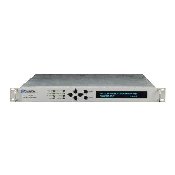
Page 36: Physical Features
Chapter 6. FRONT PANEL OPERATION The LED indicators, keypad, and VFD (Figure 1-3) are described in detail in Chapter 6. FRONT PANEL OPERATION. Figure 1-3. CDM-760 Front Panel View LED Indicators The LEDs show a summary status of modem operation. -
Page 37: Rear Panel Features
External cables are attached to connectors provided on the rear panel of the unit (Figure 1-4). (TOP) Standard AC Unit (w/optional PIIC) (MIDDLE) AC Unit (w/optional High-Speed Packet Processor) (BOTTOM) Optional 48V DC Unit Figure 1-4. CDM-760 Rear Panel View 1.2.3.2.1 Rear Panel Standard Features Utility and Traffic Data Interfaces: •... -
Page 38: Rear Panel Optional Features
48 VDC BUC 150 Watt Power Supply (AC Input or DC Input versions). FUTURE 1.2.4 Verification The CDM-760 includes many test modes and loopbacks for rapid verification of the correct functioning of the unit. Of particular note is the IF loopback, which permits the user to perform a quick diagnostic test without having to disturb external cabling. -
Page 39: On-Site Firmware Updates
Introduction Revision 4 CDM-760 Advanced High-Speed Trunking Modem MN-CDM760 During IF loopback, all of the receive configuration parameters are temporarily changed to match those of the transmit side, and an internal IF switch connects the modulator output to the demodulator input. When normal operation is again selected, all of the previous values are restored. -
Page 40: Monitor And Control Interfaces
Introduction Revision 4 CDM-760 Advanced High-Speed Trunking Modem MN-CDM760 1.2.7 Monitor and Control Interfaces • Chapter 6. FRONT PANEL OPERATION • Chapter 7. ETHERNET INTERFACE OPERATION • Chapter 8. SERIAL INTERFACE OPERATION The unit is managed through multiple interfaces providing options for both in-band (over satellite) and out-of-band monitor and control. -
Page 41: Environmental And Physical
Introduction Revision 4 CDM-760 Advanced High-Speed Trunking Modem MN-CDM760 1.3.2 Environmental and Physical Operating 0 to 50ºC (32 to 122ºF) Temperature Storage -40 to 70ºC (-40 to 158ºF) Humidity 95% maximum, non-condensing AC 100-240 VAC, 50/60 Hz Power Supply Input... -
Page 42: Demodulator (Dual If)
Introduction Revision 4 CDM-760 Advanced High-Speed Trunking Modem MN-CDM760 L-Band Monitor Port Impedance 50 Ω (available in modulator only or modem configuration) Port Connector SMA Female Port Level -27 dBm ± 3dBm Port Isolation 20 dB min Monitor Frequency 70/140 MHz: 900+70/140 MHz, L-Band: same. -
Page 43: Figure 1-5. 70/140 Mhz Input Level Vs. Symbol Rate
Introduction Revision 4 CDM-760 Advanced High-Speed Trunking Modem MN-CDM760 Figure 1-5. 70/140 MHz Input Level vs. Symbol Rate Figure 1-6. L-Band Input Level vs. Symbol Rate 1–12... -
Page 44: Es/No Performance
Introduction Revision 4 CDM-760 Advanced High-Speed Trunking Modem MN-CDM760 1.3.6.1 Es/No Performance • Chapter 6. FRONT PANEL OPERATION, Tables 6-3 through 6-5 • Appendix B. EsNo MEASUREMENT • As per DVB-S2 QEF PER 10-7 Specifications (Normal Frames) • Applies with one like-modulated carrier spaced 1.3 x Symbol Rate and 10 dB higher than the desired carrier •... - Page 45 Introduction Revision 4 CDM-760 Advanced High-Speed Trunking Modem MN-CDM760 DVB-S2-EB1 / EB2*, Normal Block, Pilot ON, QEF (PER 1E-7) AWGN Linear Channel Min SR Max SR Min DR Max DR Spec Eff QEF Eb/No QEF Es/No (Msps) (Msps) (Mbps) (Mbps)
-
Page 46: Adaptive Coding And Modulation (Acm)
Introduction Revision 4 CDM-760 Advanced High-Speed Trunking Modem MN-CDM760 DVB-S2X (in addition to DVB-S2 ModCods), Normal Block, Pilot ON, QEF (FER 1E-5) AWGN Linear Channel Min SR Max SR Min DR Max DR Spec Eff QEF Eb/No QEF Es/No (Msps) -
Page 47: Doubletalk ® Carrier-In-Carrier ® (Cnc)
Introduction Revision 4 CDM-760 Advanced High-Speed Trunking Modem MN-CDM760 Updates to the MODCOD can happen up to 4 times per second (no restriction on distance between Max ModCod update rate MODCODs) Minimum and Maximum ModCod Remote Demodulator Unlock options: Maintain current ModCod •... -
Page 48: Chapter 2. Installation
Unpack and Inspect the Equipment Figure 2-1. Unpack and Inspect the Shipment The CDM-760 Advanced High-Speed Trunking Modem, its optional Installation and Operation Manual (otherwise available online at http://www.comtechefdata.com), and its power cord were packaged and shipped in a reusable cardboard carton containing protective foam spacing. -
Page 49: Install The Unit Into A Rack Enclosure
Comtech EF Data to submit a damage report. Read the manual. Install the Unit Into a Rack Enclosure Install the CDM-760 in its assigned position in the rack enclosure (Figure 2-2). Use, as required: • A standard rack-mounted shelf;... -
Page 50: Figure 2-2. Install The Unit Into A Rack Enclosure
Installation Revision 4 CDM-760 Advanced High-Speed Trunking Modem MN-CDM760 Feature Description Custom Rack Enclosure CDM-760 Unit Standard Rack Shelving Rack Enclosure Threaded Front Rail (typical) Unit Front Panel User-supplied Screws Figure 2-2. Install the Unit Into a Rack Enclosure 2–3... -
Page 51: Install The Optional Rear Support Brackets Kit
Installation Revision 4 CDM-760 Advanced High-Speed Trunking Modem MN-CDM760 2.2.1 Install the Optional Rear Support Brackets Kit Feature Description Back of Unit Rack Enclosure Threaded Rear Mounting Rail (typical) KT-0000XXX Primary Rear Support Brackets Kit Quantity Item CEFD Part Number... - Page 52 Do these steps to install the brackets kit (Figure 2-3): Step Description Assemble the Adapter Plates to the back sides of the CDM-760 chassis using the #10 Flat Head Screws. Assemble the #10 Shoulder Screws through the Adapter Plate mounting slots using the #10 Flat Washers, #10 Split Washers, and #10 Hex Nuts.
-
Page 53: Install The Optional Bearingless Rack Slide Set
Figure 2-4. Install the Optional Bearingless Rack Slide Set The optional FP/SL0006 Bearingless Rack Slide Set may be installed into the equipment rack enclosure and onto the sides of the CDM-760. Do these steps to install the slide set (Figure 2-4):... -
Page 54: Chapter 3. Rear Panel Connections
(Type ‘N’ shown) Figure 3-1. Coaxial Connector Examples The types of coaxial cables used by Comtech EF Data are ‘BNC’, ‘TNC’, ‘N’, ‘F’, and ‘SMA’. Coaxial cables (plugs) and their mating connectors (jacks/sockets) are available in two coupling styles –... -
Page 55: Type 'Bnc
Rear Panel Connections Revision 4 CDM-760 Advanced High-Speed Trunking Modem MN-CDM760 • Threaded Coupling Style: The jack features external threads. The plug shell features internal threads, and has either a knurled outer surface to permit hand-tightening of the connection, or hex flats to accommodate torqued installation. -
Page 56: D-Subminiature Cable Connections
Rear Panel Connections Revision 4 CDM-760 Advanced High-Speed Trunking Modem MN-CDM760 3.1.2 D-Subminiature Cable Connections Type ‘D’ Connection Type Example Chassis Receptacles: Female (top) Male (bottom) Type ‘D’ Cable with Jack Screws (female shown) Figure 3-2. D-Subminiature Connector Examples D-Subminiature connectors are also called Type ‘D’ or ‘D-Sub’ connectors. The connector pair features multiple rows of pins (male side) coupled to mating sockets (female side). -
Page 57: Cabling Connections
Appendix F. OPTIONAL HIGH-SPEED PACKET PROCESSOR. (TOP) Standard AC Unit (BOTTOM) Optional 48V DC Unit (FUTURE) Figure 3-3. CDM-760 Cabling Connections Table 3-1. CDM-760 Rear Panel Connectors Group Name Ref Des Name Connector Type Function (See Sect.) -
Page 58: If Connector Group
Rear Panel Connections Revision 4 CDM-760 Advanced High-Speed Trunking Modem MN-CDM760 3.2.1 IF Connector Group CAUTION THERE MAY BE DC VOLTAGES PRESENT ON THE TYPE ‘N’ RX AND TX IF CONNECTORS, UP TO A MAXIMUM OF 48 VOLTS. 3.2.1.1 Rx Connectors The J9 | L-BAND RX IN Type ‘N’... -
Page 59: Utility Connector Group
Rear Panel Connections Revision 4 CDM-760 Advanced High-Speed Trunking Modem MN-CDM760 3.2.2 Utility Connector Group 3.2.2.1 J1 | ALARM Connector, DB-15M The J1 | ALARM 15-pin Type ‘D’ male (DB-15M) connector provides the unit alarms interface. The connector pinouts are as follows:... -
Page 60: J2 | Redundancy Connector, Db-9F
Rear Panel Connections Revision 4 CDM-760 Advanced High-Speed Trunking Modem MN-CDM760 3.2.2.2 J2 | REDUNDANCY Connector, DB-9F The J2 | REDUNDANCY 9-pin Type ‘D’ female (DB-9F) connector provides the 1:1 control interface. It provides serial communications to transfer configuration information from the Primary to the Backup modem, and a Fault/Clock signal to signal the switch when a fault occurs. -
Page 61: J4 | Mgmt Connector, Rj-45F
Rear Panel Connections Revision 4 CDM-760 Advanced High-Speed Trunking Modem MN-CDM760 3.2.2.4 J4 | MGMT Connector, RJ-45F The RJ-45 female J4 | MGMT connector is an auto-sensing, auto-crossover port. It is reserved for use as 10/100/1000 Ethernet-based remote management and control (M&C). -
Page 62: Terrestrial Data Connector Group
Rear Panel Connections Revision 4 CDM-760 Advanced High-Speed Trunking Modem MN-CDM760 3.2.3 Terrestrial Data Connector Group 3.2.3.1 J5 | DATA, J6 | DATA Connections, RJ-45F DO NOT MIX products of different speeds (e.g., 10BaseT on J5, 100BaseT on J6, and GigE on J7), or different duplex operation (e.g., half duplex on J5 and full duplex on... -
Page 63: J7 | Optical Connection, 1000Base-Sx Cage
Install the module as shown in Figure 3-4. Note that this type of installation is typical for installation of an optional SFP module, whether in the CDM-760 chassis J7 | OPTICAL port, or using the optional STM-1 Copper or OC-3 Single/Multi Mode PIIC module kits. -
Page 64: Optional Piic Data Interface Slots
KT-0000257 SFP OC-3 Multi Mode PIIC Module PL-0022015 DVB ASI Asynchronous Serial Interface PIIC Module For traffic data types not listed, contact Comtech EF Data Product Support about additional PIIC module availability. Step Task Remove either PIIC slot blank panel by loosening the captive thumbscrews. -
Page 65: Optional High-Speed Packet Processor Connections
Appendix F. OPTIONAL HIGH-SPEED PACKET PROCESSOR Figure 3-7. Optional High-Speed Packet Processor You may order the CDM-760 factory-equipped with the optional High-Speed Packet Processor card. It is also available as a field upgrade using CEFD Kit KT-0020958. The card installs into the modem rear panel chassis space otherwise occupied by the PIICs (Figure 3-7). -
Page 66: Ground And Power Connections
Rear Panel Connections Revision 4 CDM-760 Advanced High-Speed Trunking Modem MN-CDM760 Ground and Power Connections 3.3.1 Chassis Ground Interface Figure 3-8. Chassis Ground Interface Use the #10-32 stud, located adjacent to the power interface (Figure 3-8), for connecting a common chassis ground among equipment. -
Page 67: 230V Alternating Current (Ac) Power Interface (Standard)
Rear Panel Connections Revision 4 CDM-760 Advanced High-Speed Trunking Modem MN-CDM760 3.3.2 115V/230V Alternating Current (AC) Power Interface (Standard) Feature Description On / Off Switch Press-fit Fuse Holder IEC Three-prong Connector AC Power Specifications 48 watts (typical with TPC/LDPC Codec and... -
Page 68: Ac Operation - Replace The Fuses
Rear Panel Connections Revision 4 CDM-760 Advanced High-Speed Trunking Modem MN-CDM760 3.3.2.2 AC Operation – Replace the Fuses For AC operation, the unit uses two common 5mm x 20mm Slow-blow fuses – one each for line and neutral connections. The fuses are contained on the rear panel in a fuse holder that is press- fit into the body of the IEC power module (Figure 3-11). -
Page 69: Direct Current (Dc) Power Interface (Optional)
Rear Panel Connections Revision 4 CDM-760 Advanced High-Speed Trunking Modem MN-CDM760 3.3.3 48V Direct Current (DC) Power Interface (Optional) Feature Description On / Off Switch Power Terminal Block Screw-in Fuse Holders / Receptacles DC Power Specifications 48 watts (typical with TPC/LDPC Codec and CnC... -
Page 70: Dc Operation - Replace The Fuses
Rear Panel Connections Revision 4 CDM-760 Advanced High-Speed Trunking Modem MN-CDM760 3.3.3.2 DC Operation – Replace the Fuses For DC operation, the unit requires two different fuses. The fuses are located on the rear panel in the individual screw-in receptacles found below the terminal block (Figure 3-14). - Page 71 Rear Panel Connections Revision 4 CDM-760 Advanced High-Speed Trunking Modem MN-CDM760 Notes: 3–18...
-
Page 72: Chapter 4. Updating Firmware
1) Before attempting any Ethernet FTP upload, read this important section about conditional firmware update requirements. 2) Make sure to operate the CDM-760 with its latest available firmware. If your modem is running an obsolete firmware version, these restrictions apply as to... -
Page 73: About Firmware File Acquisition And Modem Update
Microsoft Windows-based PC, running the latest version of Java, either to the CDM-760 rear panel J4 | MGMT RJ-45 M&C port or, when the optional High-Speed Packet Processor is installed and enabled, the P0 | MGMT RJ-45 M&C port. -
Page 74: Get Started: Prepare For The Firmware Download
For the SERIAL interface, use a 9-pin serial cable to connect the J3 | REMOTE port to the User PC serial port. For the ETHERNET interface, use a CAT5e Ethernet cable to connect the CDM-760 to the User PC Ethernet port: •... -
Page 75: Get The Cdm-760 Management Ip Address And Firmware Information
1. On the CDM-760 – Turn on the power. (Left) Optional CDM-760 48V DC Unit (Right) Standard CDM-760 115V/230V AC Unit 2. Use any of the following methods to obtain the CDM-760 Ethernet Management IP Address and firmware information: a. Use the CDM-760 Front Panel menus: o Ethernet Management IP Address –... -
Page 76: Make A Temporary Folder (Subdirectory) On The User Pc
Updating Firmware Revision 4 CDM-760 Advanced High-Speed Trunking Modem MN-CDM760 4.2.1.4 Make a Temporary Folder (Subdirectory) on the User PC The temporary folder is where you store the firmware archive download. There are several ways you can make a temporary folder on a Windows PC: •... -
Page 77: Use Windows Explorer To Make A Folder
Updating Firmware Revision 4 CDM-760 Advanced High-Speed Trunking Modem MN-CDM760 4.2.1.4.2 Use Windows Explorer to Make a Folder Do these steps: 1. Left-double-click the Windows Explorer icon on the Windows Desktop. 2. Depending in your Windows OS version: select File > New > Folder, or click your Folder Destination (e.g., Windows (C:)) and then New Folder to make the new, temporary folder in... -
Page 78: Use Windows Command-Line Or Command Prompt To Make A Folder
4. On the Flash Updates Index page – Select the (Select a Product Line) Satellite Modems hyperlink. 5. On the Satellite Modems product page – Select the CDM-760 product hyperlink. 6. Select the appropriate firmware archive EXE or ZIP file download hyperlink (see Section 4.1.1). - Page 79 CDM-760 modems running FW Vers. 1.1.1 through 1.3.1. • About File Archive Formats – Comtech EF Data provides its downloadable files in two compressed archive formats: *.exe (self-extracting) and *.zip (compressed). Some firewalls do not allow the download of self-extracting *.exe files.
-
Page 80: Use Windows Desktop To View Folder Contents
Updating Firmware Revision 4 CDM-760 Advanced High-Speed Trunking Modem MN-CDM760 • For ZIP files: o Click [Open] to open the archive file. Use the WinZip features to select the files for extraction to your destination folder. o Click [Save] to download the ZIP file to your Windows Downloads folder. Once... -
Page 81: Upload The Firmware Files And Update The Cdm-760 Unit
• Your CDM-760 is connected to a user-supplied, Windows-based PC running the latest version of Java, and: o The PC Ethernet port is connected to the CDM-760 rear panel J4 | MGMT RJ-45 port (alternately, if the optional High-Speed Packet Processor is installed and enabled, the P0 | MGMT RJ-45 port) with a user-supplied hub, switch, or direct Ethernet cable connection. - Page 82 CDM-760 Advanced High-Speed Trunking Modem MN-CDM760 • From the CDM-760 Front Panel, use the arrow keys to view the SELECT: Utility → Firmware screen. The top line of this screen displays the running active image as “ActiveImage:1” or “ActiveImage:2”. The FTP upload procedure will overwrite the standby image.
-
Page 83: Use The Http Interface To Perform The Ethernet Ftp Upload Procedure
Procedure For Firmware Version 1.4.1 and later, the Administrator may use the Admin | Upgrade page to manage the CDM-760 Firmware Upgrade process. Figure 4-1. HTTP Interface Admin | Upgrade page Do the steps displayed in the Firmware Upgrade section of this page to transfer the extracted firmware update image ZIP file (available from www.comtechefdata.com... -
Page 84: Select The Updated Firmware For Modem Operation
MN-CDM760 4.4.4 Select the Updated Firmware for Modem Operation Do these steps: 1. Use the CDM-760 Front Panel to make note of the current Active Image on the SELECT: Utility → Firmware screen: Firmware Images: ActiveImage: 2 ( ) Info Select Then, on the bottom line, use the ◄►arrow keys to select Select. -
Page 85: Reboot The Modem
Once the modem reboots, the Web browser prompts you to re-enter the User Name and Password in order to resume use of the HTTP Interface. The CDM-760 is now operating with its latest firmware. The firmware update process is now complete. -
Page 86: Chapter 5. Fast Activation Procedure
In order to permit a lower initial cost, you may purchase the unit enabled with only the desired features. If you wish to upgrade the functionality of a unit at a later date, Comtech EF Data provides Fully Accessible System Topology (FAST), which permits the purchase and activation of options through special authorization codes. -
Page 87: About Fast Options
DVB-S2-EB1/EB2X Network Specification), and DPD options. Note the following: • When a FAST Access Code is obtained from Comtech EF Data, it will be for a specific register. • The CnC and K4 GZip FAST options require installation of the respective option card into the internal modem board. -
Page 88: Fast Activation Using The Cdm-760 Http (Web Server) Interface
1. Before contacting Comtech EF Data Product Support to order FAST feature upgrades, obtain and record the modem’s baseboard serial number: a. Log in to the CDM-760 HTTP Interface, and open the ‘Status | Info’ page. The serial number is provided in the General Information section of this page: b. - Page 89 CDM-760 Advanced High-Speed Trunking Modem MN-CDM760 2. To view currently installed FAST features, log in to the CDM-760 HTTP Interface and open the ‘Status | Info’ page. The FAST information appears in the Installed Options and Uninstalled Options sections of this page, as this example shows: 3.
-
Page 90: Chapter 6. Front Panel Operation
Overview Figure 6-1. CDM-760 Front Panel View Figure 6-1 shows the CDM-760 front panel operational features: LED Indicators – These eight LEDs show the summary status of key modem operations. Keypad – Use the keypad to ENTER data. The keypad has six individual keys. The keys have a positive ‘click’... -
Page 91: Led Indicators
1:N redundancy system. There is a Stored Event in the log. View stored events from the front panel, the remote Amber STORED control interface, or the CDM-760 HTTP (Web Server) Interface. EVENT There are no Stored Events. Green The Tx IF is ON. -
Page 92: Keypad
Front Panel Operation Revision 4 CDM-760 Advanced High-Speed Trunking Modem MN-CDM760 6.1.2 Keypad The keypad has an auto-repeat feature. When you hold down a key for more than 1 second, the key action repeats at the rate of 15 keystrokes per second. This is particularly useful when editing numeric fields with many numbers, such as frequency or data rate. -
Page 93: Opening Screen
Front Panel Operation Revision 4 CDM-760 Advanced High-Speed Trunking Modem MN-CDM760 6.1.3.1 Opening Screen The opening screen appears when you first apply power to the unit: Comtech CDM-760 Advanced High-Speed Trunking Modem ver. X.X.X This screen identifies the product and the version number of the installed firmware (e.g., ver. -
Page 94: Front Panel Menus
CDM-760 Advanced High-Speed Trunking Modem MN-CDM760 CDM-760 Front Panel Menus The primary and nested menus available from the CDM-760 front panel are described in this section. The actual choices displayed in the submenus depend on which FAST options are enabled. Where a FAST option affects a menu, this is explained in the sections that follow in this chapter. -
Page 95: Select: (Main) Menu
Front Panel Operation Revision 4 CDM-760 Advanced High-Speed Trunking Modem MN-CDM760 6.2.1 SELECT: (Main) Menu When the modem is running with Carrier-in-Carrier installed and turned ON, you will see the blinking “CnC” symbol, shown here, at the far right of the top line of the SELECT: (main), SELECT: Monitor, and SELECT: TEST menu screens. -
Page 96: Config:) Netspec
(this impacts both the Tx and Rx paths). Use the arrow keys to select DVB-S1 (Open Network Standard Operation), DVB-S2-EB1 or DVB-S2-EB2 (Comtech EF Data’s Efficiency Boost Rev. 1 or Rev. 2 Closed Network Standard Operation), or DVB-S2X (DVB-S2 Extended). Press ENTER. -
Page 97: Config:) Tx
Front Panel Operation Revision 4 CDM-760 Advanced High-Speed Trunking Modem MN-CDM760 When you select an Operating Mode other than what is active, the front panel displays this message: Configuring Operating Mode Please Wait 6.2.2.2 (CONFIG:) Tx Tx: Mod Data Freq... - Page 98 Front Panel Operation Revision 4 CDM-760 Advanced High-Speed Trunking Modem MN-CDM760 Network Spec QPSK 8PSK 16APSK 32APSK 64APSK 1/2, 8/15, 17/30, 17/30, 3/5, 19/30, 19/30, 2/3, 3/5, 19/30, 2/3, 127/180, 3/4, 4/5, 2/3, 127/180, 3/4, 127/180, 3/4, 4/5, 4/5, 5/6, 31/36, 8/9,...
-
Page 99: Config: Tx) Data
Front Panel Operation Revision 4 CDM-760 Advanced High-Speed Trunking Modem MN-CDM760 6.2.2.2.2 (CONFIG: Tx) Data Tx Data Rate Tx Symbol Rate () Use the arrow keys to select Tx Data Rate or Tx Symbol Rate. Press ENTER. (CONFIG: Tx) Data Tx Data Rate... - Page 100 Front Panel Operation Revision 4 CDM-760 Advanced High-Speed Trunking Modem MN-CDM760 Data Rate Values: The maximum limits for the Data Rate are based on a symbol rate range from 0.1 to 150 Msps. The actual minimum and maximum data rates are dependent on Network Spec, Framing mode, Interface type, Modulation type and FEC Code Rate settings.
-
Page 101: Table 6-3. Dvb-S2 Symbol Rate / Data Rate Range For Standard Fecframe
Front Panel Operation Revision 4 CDM-760 Advanced High-Speed Trunking Modem MN-CDM760 Table 6-3. DVB-S2 Symbol Rate / Data Rate Range for Standard FECFrame DVBS2, Normal Block, Pilot ON, QEF (PER 1E-7) AWGN Linear Channel Min SR Max SR Min DR... -
Page 102: Table 6-4. Dvb-S2-Eb1/Eb2 Symbol Rate / Data Rate Range For Standard Fecframe
Front Panel Operation Revision 4 CDM-760 Advanced High-Speed Trunking Modem MN-CDM760 Table 6-4. DVB-S2-EB1/EB2 Symbol Rate / Data Rate Range for Standard FECFrame DVB-S2-EB1 / EB2*, Normal Block, Pilot ON, QEF (PER 1E-7) AWGN Linear Channel Min SR Max SR... -
Page 103: Table 6-5. Dvb-S2X Symbol Rate / Data Rate Range For Standard Fecframe
Front Panel Operation Revision 4 CDM-760 Advanced High-Speed Trunking Modem MN-CDM760 Table 6-5. DVB-S2X Symbol Rate / Data Rate Range for Standard FECFrame DVB-S2X (in addition to DVB-S2 ModCods), Normal Block, Pilot ON, QEF (FER 1E-5) AWGN Linear Channel Min SR... -
Page 104: Config: Tx) Freq (Frequency)
Front Panel Operation Revision 4 CDM-760 Advanced High-Speed Trunking Modem MN-CDM760 6.2.2.2.3 (CONFIG: Tx) Freq (Frequency) Freq:1200.0000 MHz Spectrum:Normal Txα:.20 GoldCode:000000 () Use the arrow keys to select a parameter. Press ENTER. (CONFIG: Tx) Freq Freq Use the arrow keys to select a digit, and then use the arrow keys to change that digit. -
Page 105: Config: Tx) Power
Front Panel Operation Revision 4 CDM-760 Advanced High-Speed Trunking Modem MN-CDM760 6.2.2.2.4 (CONFIG: Tx) Power Tx: Carrier:On Level:-25.0dBm PowerControl: Manual AUPC () Use the arrow keys to select a parameter. Press ENTER. (CONFIG: Tx) Power Carrier Use the arrow keys to select On or Off. - Page 106 Front Panel Operation Revision 4 CDM-760 Advanced High-Speed Trunking Modem MN-CDM760 AUPC Compensation Rate: As with any closed-loop control system, the loop parameters must be chosen to ensure stability at all times. Several features are incorporated to ensure that the AUPC system does overshoot, or oscillate: •...
- Page 107 If the Nominal level is not set in ideal conditions, it will cause overdriving of the link during ideal conditions. Comtech EF Data strongly suggests that you enter this value when both sides of the link are in clear sky condition. This gives you the lowest possible Tx output power, and is ideal for setting the Nominal level.
-
Page 108: Config: Tx) Acm (Adaptive Coding And Modulation)
Front Panel Operation Revision 4 CDM-760 Advanced High-Speed Trunking Modem MN-CDM760 Valid settings are: Total Output Power Range of CDM-760 IF Frequency Minimum Maximum Step Size 70 / 140 MHz (50-180 MHz in 100 Hz Steps) 0 dBm -25 dBm 0.1 dBm... - Page 109 ACM messages. Use the arrow keys to select an action. Press ENTER. Comtech EF Data recommends that you use “Min” as the go-to option. This is important, because the ACM system depends on the feedback of the SNR metric from the remote demodulator to find the optimum ModCod.
- Page 110 The ACM algorithm has an extremely fast ACM messaging system – the CDM-760 sends ACM messages to the far side transmitter every 100 ms. As fast as the ACM messages are transmitted, there are many other factors in an ACM environment to consider that impact the overall service.
-
Page 111: Config: Tx) Wanbuff
Front Panel Operation Revision 4 CDM-760 Advanced High-Speed Trunking Modem MN-CDM760 (CONFIG: Tx) ACM ConfigDegradation Degradation: QPSK=0.0 8PSK=0.0 16QAM=1.0 32APSK=2.0 () Add a level of signal margin to the QEF switch points in ACM operation. Do this by adding a degradation value for each modulation type. -
Page 112: Config:) Rx
Front Panel Operation Revision 4 CDM-760 Advanced High-Speed Trunking Modem MN-CDM760 1) If you are in MultiStream Mode, the buffer depth is calculated using only the Ethernet data rate – not the aggregate data rate. 2) The WAN Buffer is a FIFO (First In First Out) buffer, not a circular buffer. This... -
Page 113: Config: Rx) Data
Front Panel Operation Revision 4 CDM-760 Advanced High-Speed Trunking Modem MN-CDM760 Network Spec QPSK 8PSK 16APSK 32APSK 64APSK 1/2, 8/15, 17/30, 17/30, 3/5, 19/30, 19/30, 2/3, 3/5, 19/30, 2/3, 2/3, 127/180, 3/4, 127/180, 3/4, 4/5, 127/180, 3/4, 4/5, DVB-S2-EB1 127/180, 3/4, 4/5,... -
Page 114: Config: Rx) Freq (Frequency)
Front Panel Operation Revision 4 CDM-760 Advanced High-Speed Trunking Modem MN-CDM760 (CONFIG: Rx) Data Rx Symbol Rate Rx Sym Rate = 060140.976 ksps () Set the Rx Symbol Rate to match the Tx Symbol Rate of the distant end modulator. Use the ... -
Page 115: Config: Rx) Esno
Front Panel Operation Revision 4 CDM-760 Advanced High-Speed Trunking Modem MN-CDM760 6.2.2.3.4 (CONFIG: Rx) EsNo Receive EsNo Alarm Point = -03.0 dB () Use the arrow keys to select a digit, and then use the arrow keys to change that digit. -
Page 116: Table 6-6. Config: Intf Screen
Front Panel Operation Revision 4 CDM-760 Advanced High-Speed Trunking Modem MN-CDM760 Table 6-6. Config: Intf Screen Indication Interface (Top line) Description (Bottom Line) The GbE interface is Off. The PHY is down. The interface is in Tri-state mode and all LED indicators are non-functioning. -
Page 117: Single Stream Mode Or Multistream Mode Operation
Front Panel Operation Revision 4 CDM-760 Advanced High-Speed Trunking Modem MN-CDM760 6.2.2.4.1 Single Stream Mode or MultiStream Mode Operation Single Stream Mode is the conventional method for transporting a single type of traffic data over the satellite. MultiStream Mode allows more than one type of traffic data to be active at the same time. - Page 118 Front Panel Operation Revision 4 CDM-760 Advanced High-Speed Trunking Modem MN-CDM760 Step Task Make sure that both interface slots (PIIC1 and PIIC2) are set as either NONE (not installed) or OFF (not active). You will know the total Tx data rate that the modem permits after completing this step.
-
Page 119: Config: Intf) (Gbeix)
10BASE-T Half 10 Base-T Half Duplex ** Forced 1000 Base-T Full Duplex is a non-standard mode of operation. Comtech EF Data strongly recommends that you ALWAYS run 1000 Base-T (GbE) ports in Auto Negotiate mode. (CONFIG: INTF) (GBEIX) Status This read-only column displays the port’s current operating speed when you set the speed to... -
Page 120: Mac Learning Operational States
Front Panel Operation Revision 4 CDM-760 Advanced High-Speed Trunking Modem MN-CDM760 (CONFIG: INTF) (GBEIX) FlowControl The use of Flow Control or Pause Frames is useful when ALL devices connected to the modems are set to honor Pause Frames. When used properly, Flow Control acts as a traffic valve in an ACM environment. -
Page 121: Figure 6-2. Mac Learning Operations
Front Panel Operation Revision 4 CDM-760 Advanced High-Speed Trunking Modem MN-CDM760 Frame going from WAN to LAN (Rx): Source MAC Destination MAC Action Don’t care Unknown Packet is sent to LAN, Source MAC is learned to exist on WAN Don’t care... -
Page 122: Config: Intf) (Optical)
Front Panel Operation Revision 4 CDM-760 Advanced High-Speed Trunking Modem MN-CDM760 6.2.2.4.3 (CONFIG: INTF) (Optical) If the CONFIG: Intf menu displays NONE, then the optional Optical Gigabit Ethernet Interface SFP is either NOT plugged into the J7 | OPTICAL socket, or the Optical Gigabit Ethernet Interface FAST Option is not activated. - Page 123 EXT CLK, RX SAT, or TX CLK. Press ENTER. Comtech EF Data strongly suggests that you select TX CLK, unless a high- stability EXT CLK is present and timing of the network requires all devices to be locked to the EXT CLK.
- Page 124 Front Panel Operation Revision 4 CDM-760 Advanced High-Speed Trunking Modem MN-CDM760 Selection (Alarm) Description External Clock In Range means that the External Clock is set by the TxClock or ExtClkInRange RxClock, but the rate of the clock on J8 | EXT REF does not agree with the rate expected by the modem.
-
Page 125: Config:) Intf (Piicx=Oc3/Stm1)
Front Panel Operation Revision 4 CDM-760 Advanced High-Speed Trunking Modem MN-CDM760 • If the Fill Status is decreasing (approaching 0%), then the Rx traffic is arriving too slowly for the Rx Clock setting, causing a data underflow. • If the Fill Status is increasing (approaching 100%), then the Rx traffic is arriving too quickly for the Rx Clock setting, causing a data overflow. - Page 126 Revision 4 CDM-760 Advanced High-Speed Trunking Modem MN-CDM760 Comtech EF Data strongly suggests that you select TX CLK, unless a high- stability EXT CLK is present and timing of the network requires all devices to be locked to the EXT CLK.
-
Page 127: Config:) Intf (Piicx=Asi)
Front Panel Operation Revision 4 CDM-760 Advanced High-Speed Trunking Modem MN-CDM760 Causes Unit Status Mutes Mask Type Fault State Redundancy Visible Location LED Color Tx Carrier Switch Fault J1 Alarm Connector Monitor: Stored-Events log None: A masked event is Mask... -
Page 128: Config: Intf) (Piicx=Asi) Txmode
Front Panel Operation Revision 4 CDM-760 Advanced High-Speed Trunking Modem MN-CDM760 6.2.2.4.4.3.1 (CONFIG: INTF) (PIICX=ASI) TxMode TxMode:ASI-Norm Frame:TS-188 ReStamp:Off DataRate:100000.000 kbps Use the arrow keys to select a parameter. Press ENTER. (CONFIG: INTF) (PIICX=ASI) TxMode TxMode Use the ... -
Page 129: Config: Intf) (Piicx=Asi) Mask
Front Panel Operation Revision 4 CDM-760 Advanced High-Speed Trunking Modem MN-CDM760 6.2.2.4.4.3.3 (CONFIG: INTF) (PIICX=ASI) Mask TxPll:Fault TxFrmSync:Alarm InpSigLoss:Alarm more… () RxPLL:Fault RxUF:Fault RxOF:Fault () These menus set how the modem reports interface alarm or fault states. Use the arrow keys to select TxPll, InpSigLoss, TxFrmSync, or more... -
Page 130: Config: Intf) (Piicx=Asi) Center (Rx Buffer Re-Center)
Front Panel Operation Revision 4 CDM-760 Advanced High-Speed Trunking Modem MN-CDM760 6.2.2.4.4.3.5 (CONFIG: INTF) (PIICX=ASI) Center (Rx Buffer Re-Center) PIICX: TxMode RxMode ClkSource Mask BufSize:32.0mS Center:No Fill:99% () The Fill Status is a read-only status of buffer depth, reported as a percentage: •... -
Page 131: Config: Cnc) Min / Max Search Delay
The CDM-760 uses a very fast, hardware-based (FPGA and ASIC) compression engine. In most cases you do not need to worry about any limitations of the compression engine. -
Page 132: Config: Comp) Decompression
Use the arrow keys to set Decompression as Enabled or Disabled. Press ENTER. When Decompression is Enabled, Rx decompression works at all data rates regardless of the FAST-activated Tx compression. The decompression setting must match the far side CDM-760 Tx compression setting. A mismatch causes all data to be dropped. -
Page 133: Config:) Comp
Front Panel Operation Revision 4 CDM-760 Advanced High-Speed Trunking Modem MN-CDM760 To change the DPD Min or Max Search Delay: Use the arrow keys to toggle between the minimum or maximum delay value, and then use the arrow keys to edit that value. Press ENTER. -
Page 134: Config: Remote) Inband
Front Panel Operation Revision 4 CDM-760 Advanced High-Speed Trunking Modem MN-CDM760 o For Interface, use the arrow keys to select RS-232, RS-485-2W, or RS-485-4W. o For Address, note the following: For RS-232 (aka EIA-232) – The Address is fixed at 0000 and is not editable. -
Page 135: Config:) Ip
Front Panel Operation Revision 4 CDM-760 Advanced High-Speed Trunking Modem MN-CDM760 6.2.2.10 (CONFIG:) IP IP Config: Addresses SNMP () Use the arrow keys to select a parameter. Press ENTER. 6.2.2.10.1 (CONFIG: IP) Addresses IP:192.168.001.001/24 MAC:0006B00286F5 Gateway:192.001.001.100 () Use the arrow keys to select a parameter. Press ENTER. -
Page 136: Config: Ip) Snmp
Front Panel Operation Revision 4 CDM-760 Advanced High-Speed Trunking Modem MN-CDM760 (CONFIG: IP) AddressesMAC: The unit MAC address is read-only and is not selectable or editable. (CONFIG: IP) Addresses Gateway: The Gateway Address is the default next hop address used by the M&C to send traffic to the Ethernet M&C J4 | MGMT port when sending a datagram to an IP address outside of its subnet... - Page 137 Front Panel Operation Revision 4 CDM-760 Advanced High-Speed Trunking Modem MN-CDM760 On the bottom line – Use the arrow keys to select the alphanumeric character to edit, and then use the arrow keys to edit that character.
-
Page 138: Config:) Mask
Front Panel Operation Revision 4 CDM-760 Advanced High-Speed Trunking Modem MN-CDM760 On the bottom line – Use the arrow keys to select a digit, and then use the arrow keys to change that digit. Press ENTER. To disable Traps, set both Trap IP Addresses to 000.000.000.000. -
Page 139: Config:) Ref
Front Panel Operation Revision 4 CDM-760 Advanced High-Speed Trunking Modem MN-CDM760 Mask Type Unit Status LED Color Fault State Visible Location None: A masked event is not Mask None None logged and is not seen in any menu. Fault-Tx On... -
Page 140: Config:) Meo (Medium Earth Orbit)
Front Panel Operation Revision 4 CDM-760 Advanced High-Speed Trunking Modem MN-CDM760 6.2.2.13 (CONFIG:) MEO (Medium Earth Orbit) This menu is not available when in Normal (Geostationary) operation (Section 6.2.2.1.2 (CONFIG: NetSpec) Operating Mode). AntId:0 AntStat:0 SatId:None Mute:0 Handover:00 This read-only screen displays information generated by the ACU (Antenna Controller Unit). Press ENTER or CLEAR to return to the previous menu. -
Page 141: Select: Monitor
Front Panel Operation Revision 4 CDM-760 Advanced High-Speed Trunking Modem MN-CDM760 6.2.3 SELECT: Monitor Monitor: Live-Alarms Stored-Events ACM Rx-Params CnC Stats Buffer MEO DPD () Use the arrow keys to select a parameter. Press ENTER. 6.2.3.1 (Monitor:) Live-Alarms... - Page 142 Front Panel Operation Revision 4 CDM-760 Advanced High-Speed Trunking Modem MN-CDM760 State Type Alarm Unit A PIIC interface has been selected and the clock is set to lock to an PIIC1 ExtClk Out of (cont.) External Clock (as with G.703 or other Synchronous PIIC cards), however Range the clock signal does not match the expected clock rate.
-
Page 143: Monitor:) Stored-Events
Front Panel Operation Revision 4 CDM-760 Advanced High-Speed Trunking Modem MN-CDM760 State Type Alarm A PIIC interface has been selected but the data rate coming into the PIIC (Receive) PIIC1 Buffer CLK PLL card is either too high, too low or has too much jitter to generate a (cont.) -
Page 144: Monitor: Stored-Events) Clr (Clear Event Log Buffer)
Front Panel Operation Revision 4 CDM-760 Advanced High-Speed Trunking Modem MN-CDM760 6.2.3.2.2 (Monitor: Stored-Events) Clr (Clear Event Log Buffer) Event 001:001 16:21:58 25/04/14 () Info:Log ERASED Clr:Y Use the arrow keys to select Y (Yes) to clear the Stored Events buffer. The default is N (No). -
Page 145: Monitor:) Cnc (Carrier-In-Carrier Parameters)
(Monitor:) Stats (Statistics) Statistics are reported for base unit operation only. M&C for the High-Speed Packet Processor is provided on the CDM-760 HTTP Interface. See Chapter 7. ETHERNET INTERFACE OPERATION for full information about using this interface for Packet Processor operations. - Page 146 Front Panel Operation Revision 4 CDM-760 Advanced High-Speed Trunking Modem MN-CDM760 IPstats Port Selection Ref Rear Panel Connector GigE 1 J5 | DATA port GigE 2 J6 | DATA port M&C J4 | MGMT M&C 10/100 port J7 | OPTICAL port Next, on the bottom line –...
-
Page 147: Monitor: Stats) Basebandframing
Front Panel Operation Revision 4 CDM-760 Advanced High-Speed Trunking Modem MN-CDM760 (Monitor: Stats) IP Clr (Clear Statistics Buffer) Use the arrow keys to select Y (Yes) to clear the IP statistics buffer. The default is N (No). Press ENTER to clear the buffer, or press CLEAR to back out of the command and return to the previous menu. - Page 148 Front Panel Operation Revision 4 CDM-760 Advanced High-Speed Trunking Modem MN-CDM760 Tx Count Rx Count RxErrFrms Rx Frames Drppd Tx Count (8PSK 8/9) Rx Count (8PSK 8/9) RxErrFrms (8PSK 8/9) Tx Count (8PSK 9/10) Rx Count (8PSK 9/10) RxErrFrms (8PSK 9/10)
- Page 149 Front Panel Operation Revision 4 CDM-760 Advanced High-Speed Trunking Modem MN-CDM760 Tx Count Rx Count RxErrFrms Rx Frames Drppd Tx Count (16APSK 2/3) Rx Count (16APSK 2/3) RxErrFrms (16APSK 2/3) Tx Count (16APSK 127/180) Rx Count (16APSK 127/180) RxErrFrms (16APSK 127/180)
-
Page 150: Monitor: Stats) Compression
Front Panel Operation Revision 4 CDM-760 Advanced High-Speed Trunking Modem MN-CDM760 Tx Count Rx Count RxErrFrms Rx Frames Drppd Tx Count (16APSK 5/9L) Rx Count (16APSK 5/9L) RxErrFrms (16APSK 5/9L) Tx Count (16APSK 26/45) Rx Count (16APSK 26/45) RxErrFrms (16APSK 26/45) -
Page 151: Monitor:) Buffer
Front Panel Operation Revision 4 CDM-760 Advanced High-Speed Trunking Modem MN-CDM760 (Monitor: Stats) Compression View Statistics (LanToWan or WanToLAN) Bytes In 0.0E+00 Savings () Bytes Out 0.0E+00 Last 10s 00% CLR:N All statistics are read-only. Select LanToWan to view the Tx compression statistics of the modulator’s transmission path:... -
Page 152: Monitor:) Meo (Medium Earth Orbit)
Front Panel Operation Revision 4 CDM-760 Advanced High-Speed Trunking Modem MN-CDM760 When Flow Control is Enabled (see (CONFIG: INTF)(GBEIX) FlowControl in Section 6.2.2.4.2), the modem begins to send Pause Frames to any device connected to the Ethernet Data Interfaces at approximately 87% capacity. Pause Frames cease to be sent to the Ethernet Interfaces when the WAN Buffer Full Status drops below 75% capacity. -
Page 153: Select: Test
Front Panel Operation Revision 4 CDM-760 Advanced High-Speed Trunking Modem MN-CDM760 6.2.4 SELECT: Test TEST: Mode BERT Comp () Use the arrow keys to select a parameter. Press ENTER. 6.2.4.1 (TEST:) Mode Modem Test Mode:Normal () Use the arrow keys to select an available Test Mode. Press ENTER to execute. -
Page 154: Figure 6-3. Loopback Test Modes
Front Panel Operation Revision 4 CDM-760 Advanced High-Speed Trunking Modem MN-CDM760 Figure 6-3. Loopback Test Modes 6–65... -
Page 155: Test:) Bert
Front Panel Operation Revision 4 CDM-760 Advanced High-Speed Trunking Modem MN-CDM760 6.2.4.2 (TEST:) BERT BER:No Sync Count:0.0E+00 Errs:0.0E+00 BERT:On Patt:2^23-1 Restart ErrIns () On the top line – Read-only BER (Bit Error Rate) information is provided as follows: Parameter Description This is the current Bit Error Rate of the demod. -
Page 156: Test:) Led
Front Panel Operation Revision 4 CDM-760 Advanced High-Speed Trunking Modem MN-CDM760 6.2.4.4 (TEST:) LED Front Panel LED Test: Enabled (Enable, Disable) () Use the arrow keys to select Enable and then press ENTER to execute a diagnostic test on the front panel LED Indicators and the VFD. -
Page 157: Select: Utility
Front Panel Operation Revision 4 CDM-760 Advanced High-Speed Trunking Modem MN-CDM760 6.2.6 SELECT: Utility Utility: Set-RTC Display EventLog Circuit-ID Firmware Use the arrow keys to select a parameter. Press ENTER 6.2.6.1 (Utility:) Set-RTC Edit Real-Time Clock: dd/mm/yy Time: 12:01:02 Date:26/10/14 () -
Page 158: Utility:) 1:1
Front Panel Operation Revision 4 CDM-760 Advanced High-Speed Trunking Modem MN-CDM760 6.2.6.4 (Utility:) CID Appendix H. CARRIER ID (DVB-CID MetaCarrier®) CID: Lat:33 25.43’N Long:111 58.28’W ⁰ ⁰ State:On Telephone Message () Use the arrow keys to select a parameter. Press ENTER. -
Page 159: Utility:) Circuit Id
Use the arrow keys to select 1:N Redundancy as Enabled or Disabled. Press ENTER If the unit is connected to a Comtech EF Data CRS-500 M:N Redundancy System (as part of a 1:N system), this setting must set to Enabled. In all other circumstances (i.e., standalone operation or 1:1 Redundancy), 1:N Redundancy must be set to Disabled. -
Page 160: Utility:) Firmware
THESE SUBMENUS ARE INTENDED FOR DIAGNOSTIC PURPOSES ONLY. DO NOT CHANGE AN IMAGE UNLESS OTHERWISE DIRECTED BY COMTECH EF DATA PRODUCT SUPPORT. These submenus permit you to view information about the CDM-760 internal firmware, or to select which image is loaded the next time the unit reboots. -
Page 161: Odu: Buc:pwrsupply+Ref) Psu-And-10Mhz
Front Panel Operation Revision 4 CDM-760 Advanced High-Speed Trunking Modem MN-CDM760 On the bottom line – Use the arrow keys to select the standby image (in this example, Image #2) if desired. Press ENTER. You are then prompted to reboot the unit. -
Page 162: Odu: Lnb:pwrsupply+Ref) Psu-And-10Mhz
Press ENTER. (ODU: LNB:PwrSupply+Ref) PSU-and-10MHz Alarm limits The CDM-760 constantly monitors the LNB power supply source. Use this selection to define an alarm range that alerts you to problems with the LNB. On the bottom line, first use the arrow keys to select a digit to edit, and then use the ... - Page 163 HW RevXX.XX FAST (Fully Accessible System Topology) allows you to enable new options in the modem. Contact Comtech EF Data Product Support to purchase a FAST Option and acquire the associated FAST Access Code. The bottom line displays the modem’s 9-digit “Baseboard S/N” – you will need to provide this information to Comtech EF Data Product Support when ordering FAST feature upgrades.
- Page 164 “Set register#”, ‘#’ means the appropriate register #1, #2, or #3. Contact a Comtech EF Data Product Support representative to order the desired FAST options. Be prepared to provide the Modem Serial Number. Your Comtech EF Data Product Support representative will verify the order and provide an invoice and activation instructions, including a register-specific 20-digit FAST Access Code.
- Page 165 () Time remaining: 29:23:59:50 FAST Options Demo Mode allows access to ALL CDM-760 FAST options for 30 calendar days. On the top line, use the arrow keys to select Demo Mode as Off or On. Press ENTER. The bottom line displays the Time remaining – the time format is DD:HH:MM:SS (days, hours, minutes and seconds.
- Page 166 Front Panel Operation Revision 4 CDM-760 Advanced High-Speed Trunking Modem MN-CDM760 o The modem is NOT in Demo Mode. If the timer reaches 00:00:00:00, the modem will turn its Tx Off and the circuit will be down. • Time Remaining Refills In – This is the calendar year counter that resets FractionalCnCTime Remaining to its 90 full days of CnC usage when it reaches 00:00:00:00.
- Page 167 Front Panel Operation Revision 4 CDM-760 Advanced High-Speed Trunking Modem MN-CDM760 Notes: 6–78...
-
Page 168: Chapter 7. Ethernet Interface Operation
• The CDM-760 is connected to a user-supplied, Windows-based PC, and: o The PC serial port is connected to the CDM-760 rear panel J3 | REMOTE port with a user-supplied serial cable. o The PC Ethernet port is connected to either the CDM-760 rear panel J4 | MGMT 10/100 BaseT Ethernet port or the Packet Processor P0 | MGMT port with a user-supplied hub, switch, or direct Ethernet cable connection. -
Page 169: Snmp Interface
The managed device. This includes the CDM-760 Advanced High-Speed Trunking Modem. • The SNMP Agent. This is the software that runs on the CDM-760. The CDM-760 SNMP Agent • supports both SNMPv1 and SNMPv2c. The user-supplied Network Management System (NMS). This is the software that runs on •... -
Page 170: Snmp Traps
Traps Community default = comtech For correct SNMP operation, make sure to use the CDM-760 MIB files that are applicable to the version of the CDM-760 modem M&C. Read your CDM-760 FW Release Notes for information on the required firmware and software compatibility. -
Page 171: Telnet Interface
Chapter 8. SERIAL INTERFACE OPERATION Figure 7-1. Telnet Interface Example – Windows Command-line The CDM-760 has a Telnet interface for the purpose of equipment M&C via the Serial Remote Control protocol. The Telnet interface requires user login at the Administrator level and Read/Write level. Once logged into the Telnet interface as the Administrator, you have access to the optional serial-based Remote Control Interface. -
Page 172: Configure Hyperterminal For Telnet Remote Control Operation
1. Make sure to define the Connect To Telnet connection properties correctly (File Properties) (Figure 7-3, left): a. Enter the CDM-760’s Traffic/Management IP Address as the “Host address” (e.g., 192.168.1.1). b. Enter TCP Port 23 as the “Port number”. -
Page 173: Http (Web Server) Interface
MN-CDM760 HTTP (Web Server) Interface A user-supplied web browser allows the full monitor and control (M&C) of the CDM-760 from its HTTP Interface. This non-secure embedded web application is designed for, and works best with, Microsoft Internet Explorer Version 8.0 or higher. -
Page 174: Http Interface - Operational Features
HTTP Interface – Operational Features 7.4.2.1 Navigation The CDM-760 HTTP Interface features navigation tabs located at the top of each page. Once you click a navigation tab, you may click an available primary page tab. In turn, any nested tabs appear for further selection. -
Page 175: Drop-Down Lists
Ethernet Interface Operation Revision 4 CDM-760 Advanced High-Speed Trunking Modem MN-CDM760 7.4.2.4 Drop-down Lists A drop-down list lets you choose from a list of selections. Left-click the drop-down button to open the list. Then, left-click on an item to select that choice. -
Page 176: Http Interface - Menu Tree
7.4.3 HTTP Interface – Menu Tree The Figure 7-4 menu tree diagram lists the features available through the CDM-760 HTTP Interface. This interface features four navigation tabs (shown in blue). Primary page tabs (green) and nested page tabs (yellow) provide access to individual web pages. Click any navigation tab to continue. -
Page 177: Conditional Access To High-Speed Packet Processor
Appendix F. OPTIONAL HIGH-SPEED PACKET PROCESSOR Carefully review the information in this section. A large number of pages in the HTTP Interface address operation of the CDM-760 once it is equipped with the optional High-Speed Packet Processor card. These pages are accessible only when this card is installed and enabled. -
Page 178: Http Interface
Access to and availability of certain HTTP Interface pages is dependent upon the FAST options purchased and the detected presence of auxiliary or optional products installed and configured for use with the CDM-760. The subsections that follow note such conditional availability. -
Page 179: Home | Contact
Ethernet Interface Operation Revision 4 CDM-760 Advanced High-Speed Trunking Modem MN-CDM760 7.4.4.1.2 Home | Contact Use this page to see the contact information (phone, fax, or Web/e-mail hyperlinks) for Comtech EF Data Product Support. Figure 7-6. Home | Contact Page... -
Page 180: Admin (Administration)
• Use the Ping Reply drop-down list to select Enabled or Disabled: Selecting Enabled causes the CDM-760 to reply to ping requests. Selecting Disabled causes the CDM-760 to ignore ping requests and no replies are sent to ping requests. •... - Page 181 Ethernet Interface Operation Revision 4 CDM-760 Advanced High-Speed Trunking Modem MN-CDM760 System Account Access Information At the time of publication, the "SMTP Server", "SMTP Domain Name", and "SMTP Destination" text fields are non-functional. • Enter a Read-only, Read/Write, or Admin Name and Password. A name or password can be any alphanumeric combination with a maximum length of 10 characters.
-
Page 182: Admin | Snmp
Revision 4 CDM-760 Advanced High-Speed Trunking Modem MN-CDM760 7.4.4.2.2 Admin | SNMP The Administrator must use this page to manage the CDM-760 SNMP (Simple Network Management Protocol) settings. Figure 7-8. Admin | SNMP Page SNMP • Use the Simple Network Management drop-down list to select Enabled or Disabled. -
Page 183: Admin | Upgrade
Click [Set Image 1] or [Set Image 2] to specify which firmware image is loaded upon power- up (bootup) of the unit. • Click [Reboot Modem] to reboot the CDM-760. You will need to re-enter your user credentials to resume use of the HTTP Interface. 7–16... -
Page 184: Admin | Fast
Figure 7-10. Admin | FAST Page FAST Upgrade When you obtain a FAST access code from Comtech EF Data, it will be for a specific option register. Carefully enter each register-specific 20-character FAST access code in sequence, and then click [Enter#] when done. The modem then displays a message on this page to indicate whether or not the codes were accepted or if the upgrade was successful. -
Page 185: Configuration
Ethernet Interface Operation Revision 4 CDM-760 Advanced High-Speed Trunking Modem MN-CDM760 put into Demo Mode. If all options running are activated (purchased) FAST Options, the modem will not change its configuration. 7.4.4.3 Configuration Pages Use these pages to configure all unit parameters. Click the Configuration navigation tab, and then select the Modem, Interface, ARP, Routing, WAN, Utilities, Mask, Test, LNB, CID, or MEO tab to continue. -
Page 186: Configuration | Interface Pages
Chapter 6. FRONT PANEL OPERATION before you attempt to use either of the Interfaces pages. Use the Interface pages to configure and monitor the available base unit and optional Ethernet and optional PIIC traffic data interfaces at the CDM-760 rear panel: • The J5 | DATA Ethernet port •... -
Page 187: Configuration | Interface | Ethernet
Ethernet Interface Operation Revision 4 CDM-760 Advanced High-Speed Trunking Modem MN-CDM760 7.4.4.3.2.1 Configuration | Interface | Ethernet (TOP) Page Appearance w/Functional PIICs Installed (BOTTOM) Page Appearance w/Optional High-Speed Packet Processor Installed Figure 7-12. Configuration | Interface | Ethernet Page 7–20... - Page 188 Ethernet Interface Operation Revision 4 CDM-760 Advanced High-Speed Trunking Modem MN-CDM760 Absent the optional High-Speed Packet Processor, the rear panel GBEI 1 (J5 | DATA), GBEI 2 (J6 | DATA) ports and the optional Optical Ethernet SFP Module (J7 | OPTICAL) are operational and configurable.
-
Page 189: Port Configuration
Ethernet Interface Operation Revision 4 CDM-760 Advanced High-Speed Trunking Modem MN-CDM760 Address / Address Range or Rule Reason 169.254.0.XXX Comtech internal modem use 169.254.1.XXX Comtech internal modem use 224.0.0.0 – 239.255.255.255 RFC 5771 multicast addresses 240.0.0.0 – 255.255.255.255 RFC 6890 reserves IP address (future) aaa.XXX.XXX.XXX... -
Page 190: Configuration | Interface | Piic
Use the Tx Clock Source drop-down list to select Tx Clock, Ext Clock, or Rx Sat. Comtech EF Data strongly recommends that you select Tx Clock unless a high stability External Clock is present and timing of the network requires all devices to be locked to the External Clock. -
Page 191: Figure 7-13. Configuration | Interface | Piic Page
Ethernet Interface Operation Revision 4 CDM-760 Advanced High-Speed Trunking Modem MN-CDM760 (TOP) Page Appearance w/Functional G.703, OC-3 or STM-1 PIICs Installed (MIDDLE) Page Appearance w/Functional DVB ASI PIIC Installed (Banner and Menus not shown) (BOTTOM) Page Appearance w/Optional High-Speed Packet Processor Installed (PIIC Operation Non- Functional, Banner and Menus not shown) Figure 7-13. - Page 192 Use the Tx Clock Source drop-down list to select Tx Clock or Rx Sat. Comtech EF Data strongly recommends that you select Tx Clock unless a high stability External Clock is present and timing of the network requires all devices to be locked to the External Clock.
- Page 193 Ethernet Interface Operation Revision 4 CDM-760 Advanced High-Speed Trunking Modem MN-CDM760 Alarm Settings These controls are typical for all PIIC module types, except as noted. • Use the Tx Symbol Clock PLL drop-down list to select Alarm, Fault, Mask, or Fault (Tx On).
-
Page 194: Configuration | Arp (Address Resolution Protocol)
Ethernet Interface Operation Revision 4 CDM-760 Advanced High-Speed Trunking Modem MN-CDM760 7.4.4.3.3 Configuration | ARP (Address Resolution Protocol) This page is accessible only to Admin users when the optional High-Speed Packet Processor card is installed and enabled. See Sect. 7.4.3.1 for information about using conditional access pages. - Page 195 Ethernet Interface Operation Revision 4 CDM-760 Advanced High-Speed Trunking Modem MN-CDM760 Click [Submit Changes] to save. Add Static ARP This section allows you to directly add a static ARP entry should you choose to hard-code an association of an IP address to a particular MAC address. Note that the index automatically increments to the next available number.
-
Page 196: Configuration | Routing
High-Speed Packet Processor card is installed and enabled. See Sect. 7.4.3.1 for information about using these conditional access pages. 2) At present, only Point-to-Point Routing is allowed on the CDM-760. Point-to- Multipoint Routing will be enabled on future releases. - Page 197 Ethernet Interface Operation Revision 4 CDM-760 Advanced High-Speed Trunking Modem MN-CDM760 Add New Route Use the available text boxes and drop-down lists in this section to create (add) a new route. Note the following (from left to right): Column Description Index This is the read-only internal table index.
-
Page 198: Configuration | Routing | Dhcp
This prevents two devices from accidentally being configured with the same IP Address. The CDM-760 DHCP Relay feature allows you to deploy a single DHCP server at the hub that manages all of the devices throughout your remote networks. When a device on the CDM-760's network issues a DHCP request, it is relayed to the DHCP server as specified by the "DHCP Server... -
Page 199: Configuration | Routing | Dns
Ethernet Interface Operation Revision 4 CDM-760 Advanced High-Speed Trunking Modem MN-CDM760 7.4.4.3.4.3 Configuration | Routing | DNS Use this page to manage DNS (Domain Name System) caching. DNS caching at the remote site modem makes that modem fast-accessible to recently visited web sites by storing the IP Address-to-URL map at the remote modem. -
Page 200: Configuration | Wan
Ethernet Interface Operation Revision 4 CDM-760 Advanced High-Speed Trunking Modem MN-CDM760 7.4.4.3.5 Configuration | WAN Pages 1) The nested QoS and Compression pages are accessible only to Admin users when the optional High-Speed Packet Processor card is installed and enabled. -
Page 201: Configuration | Wan | Qos Page - Max/Priority, Min/Max Modes
Ethernet Interface Operation Revision 4 CDM-760 Advanced High-Speed Trunking Modem MN-CDM760 7.4.4.3.5.1.1 Configuration | WAN | QoS Page – Max/Priority, Min/Max Modes (TOP) QoS Mode = Max/Priority (Banner and Menu Bar not shown) (BOTTOM) QoS Mode = Min/Max (Banner and Menu Bar not shown) Figure 7-18. - Page 202 Ethernet Interface Operation Revision 4 CDM-760 Advanced High-Speed Trunking Modem MN-CDM760 Add New QoS Rule In ‘Max/Priority’ QoS Mode: In ‘Min/Max’ QoS Mode: Use the available text boxes and drop-down lists in this section to create a new QoS rule. Note...
- Page 203 Ethernet Interface Operation Revision 4 CDM-760 Advanced High-Speed Trunking Modem MN-CDM760 Column Description Weight Enter a weight from 1 to 100. Weighting is used either to drain traffic having the same Priority Level (“Max/Priority” mode) or to drain after the minimum bandwidth is met (“Min/Max”...
- Page 204 Ethernet Interface Operation Revision 4 CDM-760 Advanced High-Speed Trunking Modem MN-CDM760 Column Description Max BW (Kbps) Displays the assigned maximum permitted Bandwidth value. (“Max/Priority” mode only) Displays the assigned established priority (1 being the highest Priority and 8 being the lowest).
-
Page 205: Configuration | Wan | Qos Page - Diffserv Mode
Ethernet Interface Operation Revision 4 CDM-760 Advanced High-Speed Trunking Modem MN-CDM760 7.4.4.3.5.1.2 Configuration | WAN | QoS Page – DiffServ Mode QoS can be set to DiffServ Mode to make it fully compliant to the Differentiated Services QoS RFC (Request For Comments) standards. - Page 206 Ethernet Interface Operation Revision 4 CDM-760 Advanced High-Speed Trunking Modem MN-CDM760 Column Description Drop Precedences • Low Drop Precedence (% full) [0–100] – In case of congestion, the WRED is applied (cont.) after the queue depth exceeds the configured percentage value assigned for the Drop Precedence value b001.
-
Page 207: Configuration | Wan | Header Compression
Ethernet Interface Operation Revision 4 CDM-760 Advanced High-Speed Trunking Modem MN-CDM760 7.4.4.3.5.2 Configuration | WAN | Header Compression Use this page to configure optional Header and Payload Compression when this FAST feature is activated and the optional High-Speed Packet Processor is installed and enabled. -
Page 208: Configuration | Wan | Encryption (Future)
Ethernet Interface Operation Revision 4 CDM-760 Advanced High-Speed Trunking Modem MN-CDM760 7.4.4.3.5.3 Configuration | WAN | Encryption (FUTURE) Encryption is not available in this firmware release. Figure 7-21. Configuration | WAN | Encryption Page (Not Available) 7–41... -
Page 209: Configuration | Utilities
Ethernet Interface Operation Revision 4 CDM-760 Advanced High-Speed Trunking Modem MN-CDM760 7.4.4.3.6 Configuration | Utilities Figure 7-22. Configuration | Utilities Page Use the available text boxes and drop-down lists to configure your settings as needed. Click [Submit] as applicable to save. -
Page 210: Configuration | Mask
Ethernet Interface Operation Revision 4 CDM-760 Advanced High-Speed Trunking Modem MN-CDM760 7.4.4.3.7 Configuration | Mask Use this page to set a mask type for each system-level event. Figure 7-23. Configuration | Mask Page Alarm Settings Use the drop-down list for each item to select Alarm, Fault, Mask, or, where applicable, Fault-Tx... - Page 211 Ethernet Interface Operation Revision 4 CDM-760 Advanced High-Speed Trunking Modem MN-CDM760 Available Mask State Selection (Mask) Event Description FCnC Fractional Carrier-in-Carrier is common in 1:1 or 1:N redundancy systems where the primary modem is running fully operational (i.e., FAST-activated) CnC, and the backup modem(s) uses FAST- activated Fractional CnC.
-
Page 212: Configuration | Test
Ethernet Interface Operation Revision 4 CDM-760 Advanced High-Speed Trunking Modem MN-CDM760 7.4.4.3.8 Configuration | Test Figure 7-24. Configuration | Test Page See Chapter 6. FRONT PANEL OPERATION for detailed information about the Bit Error Rate Test (BERT) configuration and operation parameter controls provided on... -
Page 213: Configuration | Lnb (Low Noise Block Down Converter)
Ethernet Interface Operation Revision 4 CDM-760 Advanced High-Speed Trunking Modem MN-CDM760 7.4.4.3.9 Configuration | LNB (Low Noise Block Down Converter) This page is operational only when an optional LOW-NOISE BLOCK DOWN CONVERTER is installed. Use this page to configure Low-Noise Block Down Converter parameters. Set the desired LNB configurations. -
Page 214: Configuration: Cid (Carrier Id)
Meta-Carrier Info • The read-only MAC Address for t he M&C card on the CDM-760 is displayed here. • Set the modem’s physical location in Latitude in the form DDMM.mmC, where: o DD = degrees (00 through 90) o MM = whole minutes (00 through 60) -
Page 215: Configuration: Meo (Mid-Earth Orbit)
Ethernet Interface Operation Revision 4 CDM-760 Advanced High-Speed Trunking Modem MN-CDM760 7.4.4.3.11 Configuration: MEO (Mid-Earth Orbit) 1) You must have a G.703 PIIC plugged into PIIC Slot #1 for any MEO Operational Modes to be accessible. If a G.703 PIIC is not installed in PIIC Slot #1, then this page is nonfunctional. -
Page 216: Status
Ethernet Interface Operation Revision 4 CDM-760 Advanced High-Speed Trunking Modem MN-CDM760 7.4.4.4 Status Pages The Status pages provide you with status, event logging, and operational statistics windows. Click the Status navigation tab, and then select the Status, Logs, Info, Firmware, ACM, Traffic Statistics, BB Statistics, or Performance tab to continue. -
Page 217: Status | Logs
Ethernet Interface Operation Revision 4 CDM-760 Advanced High-Speed Trunking Modem MN-CDM760 7.4.4.4.2 Status | Logs Pages Click the Logs primary page tab, and then select the Modem Log or PP Log tab to continue. 7.4.4.4.2.1 Status | Logs | Modem Log Use this page to view logged modem faults and alarms. -
Page 218: Status | Logs | Pp Log
Ethernet Interface Operation Revision 4 CDM-760 Advanced High-Speed Trunking Modem MN-CDM760 7.4.4.4.2.2 Status | Logs | PP Log This nested page is accessible only to Admin users when the optional High-Speed Packet Processor card is installed and enabled. See Sect. 7.4.3.1 for information about using conditional access pages. -
Page 219: Status | Info
Ethernet Interface Operation Revision 4 CDM-760 Advanced High-Speed Trunking Modem MN-CDM760 7.4.4.4.3 Status | Info Use this read-only page, which updates automatically every 10 seconds, to review identifying information about the modem in its current configuration, including: • General Information •... -
Page 220: Status | Firmware
Ethernet Interface Operation Revision 4 CDM-760 Advanced High-Speed Trunking Modem MN-CDM760 7.4.4.4.4 Status | Firmware Use this read-only page to review status windows pertaining to the unit’s operational firmware loads: • The Boot Firmware section provides information for the currently loaded firmware boot applications. -
Page 221: Status | Acm
Ethernet Interface Operation Revision 4 CDM-760 Advanced High-Speed Trunking Modem MN-CDM760 7.4.4.4.5 Status | ACM Use this read-only page to view ACM (Adaptive Coding & Modulation) operating statistics. Figure 7-33. Status | ACM Status Page 7–54... -
Page 222: Status | Traffic Statistics
Ethernet Interface Operation Revision 4 CDM-760 Advanced High-Speed Trunking Modem MN-CDM760 7.4.4.4.6 Status | Traffic Statistics Pages Except where noted, these nested pages are accessible only to Admin users when the optional High-Speed Packet Processor card is installed and enabled. See Sect. -
Page 223: Figure 7-35. Status | Traffic Statistics | Ethernet Page (Packet Processor Installed/Enabled)
Ethernet Interface Operation Revision 4 CDM-760 Advanced High-Speed Trunking Modem MN-CDM760 Figure 7-35. Status | Traffic Statistics | Ethernet Page (Packet Processor Installed/Enabled) • Click [Clear] to clear/reset the Ethernet statistics buffers. • Click [Refresh] to update the page with the latest available statistics. - Page 224 Ethernet Interface Operation Revision 4 CDM-760 Advanced High-Speed Trunking Modem MN-CDM760 Ethernet Statistics Receive/Transmit Statistics Statistics Type Description Unicast Packets This is the sum for this port of all valid packets received/transmitted as Broadcast Packets Total Packets either Unicast Packets, Broadcast Packets, Multicast Packets or...
-
Page 225: Status | Traffic Statistics | Mac Table
Ethernet Interface Operation Revision 4 CDM-760 Advanced High-Speed Trunking Modem MN-CDM760 Transmit Errors Statistics Type Description Indicates two devices detected that the network is idle and try to Single Collision send packets at exactly the same time (within one round trip delay). -
Page 226: Status | Traffic Statistics | Packet Flows
Ethernet Interface Operation Revision 4 CDM-760 Advanced High-Speed Trunking Modem MN-CDM760 7.4.4.4.6.3 Status | Traffic Statistics | Packet Flows Figure 7-37. Status | Traffic Statistics | Packet Flows Page Clear Statistics • Click [Clear] to clear/reset the Packet Flows statistics buffers. -
Page 227: Status | Traffic Statistics | Router
Ethernet Interface Operation Revision 4 CDM-760 Advanced High-Speed Trunking Modem MN-CDM760 7.4.4.4.6.4 Status | Traffic Statistics | Router Use this page to review the activity on the Packet Processor card. These items are generated per the Packet Processor stack and are used primarily for system and network debugging. - Page 228 Ethernet Interface Operation Revision 4 CDM-760 Advanced High-Speed Trunking Modem MN-CDM760 Router Errors Item Description One of the following errors occurred: The TTL (Time To Live) errors is ‘0’ • IP Header Errors The packet(s) received with Unicast MAC Address does not •...
-
Page 229: Status | Traffic Statistics | Mgmtsw (Managed Switch)
Ethernet Interface Operation Revision 4 CDM-760 Advanced High-Speed Trunking Modem MN-CDM760 7.4.4.4.6.5 Status | Traffic Statistics | MgmtSW (Managed Switch) Use this page to review the overall packet count transmitted and received by the LAN (Managed Switch DATA ports P1 through P4) and the WAN (P0 | MGMT). -
Page 230: Status | Traffic Statistics | Wan
MN-CDM760 7.4.4.4.6.6 Status | Traffic Statistics | WAN Use this page to review the activity on the CDM-760 between various FPGAs and the Packet Processor. These item are used primarily for debugging internal modem routing and traffic flow issues. Figure 7-40. Status | Traffic Statistics | WAN Page Clear Statistics •... -
Page 231: Status | Traffic Statistics | Header Comp (Header Compression)
Ethernet Interface Operation Revision 4 CDM-760 Advanced High-Speed Trunking Modem MN-CDM760 7.4.4.4.6.7 Status | Traffic Statistics | Header Comp (Header Compression) Figure 7-41. Status | Traffic Statistics | Header Comp Page Clear Compression Counters • Click [Clear] to clear/reset the Header Compression statistics buffer. -
Page 232: Status | Traffic Statistics | Payld Comp (Payload Compression)
Ethernet Interface Operation Revision 4 CDM-760 Advanced High-Speed Trunking Modem MN-CDM760 7.4.4.4.6.8 Status | Traffic Statistics | Payld Comp (Payload Compression) Figure 7-42. Status | Traffic Statistics | Payld Comp Page Click [Clear Comp/Decomp Stats] to clear/reset the Payload Compression/Decompression statistics buffers. -
Page 233: Status | Traffic Statistics | Qos
Ethernet Interface Operation Revision 4 CDM-760 Advanced High-Speed Trunking Modem MN-CDM760 7.4.4.4.6.9 Status | Traffic Statistics | QoS Figure 7-43. Status | Traffic Statistics | QoS Page Clear QoS Counters • Click [Clear] to clear/reset the QoS statistics buffer. •... -
Page 234: Status | Traffic Statistics | Clear Counters
Ethernet Interface Operation Revision 4 CDM-760 Advanced High-Speed Trunking Modem MN-CDM760 7.4.4.4.6.10 Status | Traffic Statistics | Clear Counters Figure 7-44. Status | Traffic Statistics | Clear Counters Page Clear All Counters Click [Clear] to clear/reset the statistics buffers for all Traffic Statistics pages except the MAC Table and Payld Comp pages. -
Page 235: Status | Bb Statistics
Ethernet Interface Operation Revision 4 CDM-760 Advanced High-Speed Trunking Modem MN-CDM760 7.4.4.4.7 Status | BB Statistics Use this read-only page to view Modem Baseband operating statistics. Figure 7-45. Status | BB Statistics Page Click [Clear Baseband Statistics] to clear/reset the page statistics buffers. -
Page 236: Status | Performance
Ethernet Interface Operation Revision 4 CDM-760 Advanced High-Speed Trunking Modem MN-CDM760 7.4.4.4.8 Status | Performance Pages Click the Performance primary page tab, and then select the IQMon, TxGraph, Rx Graph, or CPU Usage tab to continue. 7.4.4.4.8.1 Status | Performance | IQMon This page provides you with a Constellation/Spectrum Analyzer feature. -
Page 237: Status | Performance | Txgraph
Ethernet Interface Operation Revision 4 CDM-760 Advanced High-Speed Trunking Modem MN-CDM760 7.4.4.4.8.2 Status | Performance | TxGraph Figure 7-47. Status | Performance | TxGraph Page 7–70... - Page 238 Ethernet Interface Operation Revision 4 CDM-760 Advanced High-Speed Trunking Modem MN-CDM760 When the presence of the optional K4 GZip Compression is detected, this page provides a live graphical representation of the trending characteristics that are available while using this feature.
- Page 239 Ethernet Interface Operation Revision 4 CDM-760 Advanced High-Speed Trunking Modem MN-CDM760 When more than one ModCod is used in the smallest interval period allowable by the graph, the most common ModCod used in that time interval is displayed. Tx Capacity Configuration Parameters Graphs...
-
Page 240: Status | Performance | Rxgraph
Ethernet Interface Operation Revision 4 CDM-760 Advanced High-Speed Trunking Modem MN-CDM760 7.4.4.4.8.3 Status | Performance | RxGraph Figure 7-48. Status | Performance | RxGraph Page 7–73... - Page 241 Ethernet Interface Operation Revision 4 CDM-760 Advanced High-Speed Trunking Modem MN-CDM760 When the presence of the optional K4 GZip Compression is detected, this page provides a live graphical representation of the trending characteristics that are available while using this feature.
-
Page 242: Status | Performance | Cpu Usage
Ethernet Interface Operation Revision 4 CDM-760 Advanced High-Speed Trunking Modem MN-CDM760 • NetSpec (Network Specification) – DVB-S2-EB2, DVB-S2-EB1, DVB-S2, or DVB-S2X. • Symbol Rate These parameters are shown to provide you with a more complete representation of user capacity, when viewed in conjunction with the other graphs provided on this page. - Page 243 Ethernet Interface Operation Revision 4 CDM-760 Advanced High-Speed Trunking Modem MN-CDM760 Notes: 7–76...
-
Page 244: Chapter 8. Serial Interface Operation
The PC serial port is connected to the CDM-760 rear panel J3 | REMOTE port with a user-supplied serial cable. o The PC Ethernet port is connected to either the CDM-760 rear panel J4 | MGMT 10/100 BaseT Ethernet port or the optional High-Speed Packet Processor P0 | MGMT port with a user-supplied hub, switch, or direct Ethernet cable connection. -
Page 245: Eia-485
Serial Interface Operation Revision 3 CDM-760 Advanced High-Speed Trunking Modem MN-CDM760 EIA-485 For applications where multiple devices are to be monitored and controlled, a full-duplex (or 4-wire plus ground) EIA-485 is preferred. Half- duplex (2-wire plus ground) EIA-485 is possible, but is not preferred. In full-duplex EIA-485 communication, there are two separate, isolated, independent, differential-mode twisted pairs, each handling serial data in different directions. -
Page 246: Remote Commands And Queries Overview
Serial Interface Operation Revision 3 CDM-760 Advanced High-Speed Trunking Modem MN-CDM760 Remote Commands and Queries Overview 8.4.1 Basic Protocol Whether in EIA-232 or EIA-485 mode, all data is transmitted as asynchronous serial characters, suitable for transmission and reception by a Universal Asynchronous Receiver/Transmitter (UART). -
Page 247: Start Of Packet
Serial Interface Operation Revision 3 CDM-760 Advanced High-Speed Trunking Modem MN-CDM760 Target-to-Controller (Response to Command or Query) Start of Packet Target Address Address Delimiter Instruction Code Code Qualifier Optional Arguments End of Packet > 0000 (default) =, ?, !, *, #, ~... -
Page 248: Instruction Code
Serial Interface Operation Revision 3 CDM-760 Advanced High-Speed Trunking Modem MN-CDM760 8.4.2.4 Instruction Code This is a three-character alphanumeric sequence that identifies the message subject. Uppercase alphabetic characters (‘A’ to ‘Z’, ASCII Codes 65 to 90) and the numbers ‘0’ to ‘9’ *ASCII Codes 48 to 57) may be used. Wherever possible, each instruction code is named to serve as a mnemonic for its intended operation. - Page 249 Serial Interface Operation Revision 3 CDM-760 Advanced High-Speed Trunking Modem MN-CDM760 1. If the Controller sends a query to the Target. For example: <0/TFQ? (meaning “what is the current value of the transmit frequency?”) – the Target responds with >0000/TFQ=xxxx.xxxx, the value for that queried parameter.
-
Page 250: Optional Message Arguments
Serial Interface Operation Revision 3 CDM-760 Advanced High-Speed Trunking Modem MN-CDM760 8.4.2.6 Optional Message Arguments Arguments are not required for all messages. Comma ‘,’ (ASCII Code 44), period ‘.’ (ASCII Code 46), the numbers ‘0’ to ‘9’ (ASCII Codes 48 to 57), and the uppercase alphabetic characters ‘A’... -
Page 251: Remote Commands And Queries
Serial Interface Operation Revision 3 CDM-760 Advanced High-Speed Trunking Modem MN-CDM760 Remote Commands and Queries 8.5.1 Table Indexes NOTES: 1) Index Columns – Where Column ‘C’=Command, and Column ‘Q’=Query, columns marked ‘X’ designate the instruction code as Command only, Query only, or Command or Query. - Page 252 Serial Interface Operation Revision 3 CDM-760 Advanced High-Speed Trunking Modem MN-CDM760 Sect. 8.5.5 Unit Parameters CODE PAGE CODE PAGE CODE PAGE CODE PAGE CODE PAGE 8-20 8-20 8-25 8-19 8-26 8-19 8-24 8-26 8-26 8-24 8-26 8-19 8-22 8-26 8-20...
- Page 253 Serial Interface Operation Revision 3 CDM-760 Advanced High-Speed Trunking Modem MN-CDM760 Sect. 8.5.10 ODU Parameters CODE PAGE CODE PAGE CODE PAGE CODE PAGE CODE PAGE 8-36 8-36 8-36 8-36 8-36 8-36 8-36 Sect. 8.5.11 Modem Information CODE PAGE CODE PAGE...
-
Page 254: Tx Parameters
Serial Interface Operation Revision 3 CDM-760 Advanced High-Speed Trunking Modem MN-CDM760 8.5.2 Tx Parameters Controller-to-Target Target-to-Controller Instruction Code and (see Description of Arguments) Arguments for Qualifier Description of Arguments Parameter Type Command or (Note that all arguments are ASCII numeric codes from 48 to 57) - Page 255 Serial Interface Operation Revision 3 CDM-760 Advanced High-Speed Trunking Modem MN-CDM760 Controller-to-Target Target-to-Controller Instruction Code and (see Description of Arguments) Arguments for Qualifier Description of Arguments Parameter Type Command or (Note that all arguments are ASCII numeric codes from 48 to 57)
- Page 256 Serial Interface Operation Revision 3 CDM-760 Advanced High-Speed Trunking Modem MN-CDM760 Controller-to-Target Target-to-Controller Instruction Code and (see Description of Arguments) Arguments for Qualifier Description of Arguments Parameter Type Command or (Note that all arguments are ASCII numeric codes from 48 to 57)
-
Page 257: Rx Parameters
Serial Interface Operation Revision 3 CDM-760 Advanced High-Speed Trunking Modem MN-CDM760 8.5.3 Rx Parameters Controller-to-Target Target-to-Controller Instruction Code and (see Description of Arguments) Arguments for Qualifier Description of Arguments Parameter Type Command or (Note that all arguments are ASCII numeric codes from 48 to 57) - Page 258 Serial Interface Operation Revision 3 CDM-760 Advanced High-Speed Trunking Modem MN-CDM760 Controller-to-Target Target-to-Controller Instruction Code and (see Description of Arguments) Arguments for Qualifier Description of Arguments Parameter Type Command or (Note that all arguments are ASCII numeric codes from 48 to 57)
- Page 259 Serial Interface Operation Revision 3 CDM-760 Advanced High-Speed Trunking Modem MN-CDM760 Controller-to-Target Target-to-Controller Instruction Code and (see Description of Arguments) Arguments for Qualifier Description of Arguments Parameter Type Command or (Note that all arguments are ASCII numeric codes from 48 to 57)
-
Page 260: Ip Packet Parameters
Serial Interface Operation Revision 3 CDM-760 Advanced High-Speed Trunking Modem MN-CDM760 8.5.4 IP Packet Parameters Controller-to-Target Target-to-Controller Instruction Code and (see Description of Arguments) Arguments for Qualifier Description of Arguments Parameter Type Command or (Note that all arguments are ASCII numeric codes from 48 to 57) - Page 261 Serial Interface Operation Revision 3 CDM-760 Advanced High-Speed Trunking Modem MN-CDM760 Controller-to-Target Target-to-Controller Instruction Code and (see Description of Arguments) Arguments for Qualifier Description of Arguments Parameter Type Command or (Note that all arguments are ASCII numeric codes from 48 to 57)
-
Page 262: Unit Parameters
Serial Interface Operation Revision 3 CDM-760 Advanced High-Speed Trunking Modem MN-CDM760 8.5.5 Unit Parameters Controller-to-Target Target-to-Controller Instruction Code and (see Description of Arguments) Arguments for Qualifier Description of Arguments Parameter Type Command or (Note that all arguments are ASCII numeric codes from 48 to 57) - Page 263 Serial Interface Operation Revision 3 CDM-760 Advanced High-Speed Trunking Modem MN-CDM760 Controller-to-Target Target-to-Controller Instruction Code and (see Description of Arguments) Arguments for Qualifier Description of Arguments Parameter Type Command or (Note that all arguments are ASCII numeric codes from 48 to 57)
- Page 264 Serial Interface Operation Revision 3 CDM-760 Advanced High-Speed Trunking Modem MN-CDM760 Controller-to-Target Target-to-Controller Instruction Code and (see Description of Arguments) Arguments for Qualifier Description of Arguments Parameter Type Command or (Note that all arguments are ASCII numeric codes from 48 to 57)
- Page 265 Serial Interface Operation Revision 3 CDM-760 Advanced High-Speed Trunking Modem MN-CDM760 Controller-to-Target Target-to-Controller Instruction Code and (see Description of Arguments) Arguments for Qualifier Description of Arguments Parameter Type Command or (Note that all arguments are ASCII numeric codes from 48 to 57)
- Page 266 Serial Interface Operation Revision 3 CDM-760 Advanced High-Speed Trunking Modem MN-CDM760 Controller-to-Target Target-to-Controller Instruction Code and (see Description of Arguments) Arguments for Qualifier Description of Arguments Parameter Type Command or (Note that all arguments are ASCII numeric codes from 48 to 57)
- Page 267 Serial Interface Operation Revision 3 CDM-760 Advanced High-Speed Trunking Modem MN-CDM760 Controller-to-Target Target-to-Controller Instruction Code and (see Description of Arguments) Arguments for Qualifier Description of Arguments Parameter Type Command or (Note that all arguments are ASCII numeric codes from 48 to 57)
- Page 268 Serial Interface Operation Revision 3 CDM-760 Advanced High-Speed Trunking Modem MN-CDM760 Controller-to-Target Target-to-Controller Instruction Code and (see Description of Arguments) Arguments for Qualifier Description of Arguments Parameter Type Command or (Note that all arguments are ASCII numeric codes from 48 to 57)
- Page 269 Serial Interface Operation Revision 3 CDM-760 Advanced High-Speed Trunking Modem MN-CDM760 Controller-to-Target Target-to-Controller Instruction Code and (see Description of Arguments) Arguments for Qualifier Description of Arguments Parameter Type Command or (Note that all arguments are ASCII numeric codes from 48 to 57)
-
Page 270: Acm Parameters
Serial Interface Operation Revision 3 CDM-760 Advanced High-Speed Trunking Modem MN-CDM760 8.5.6 ACM Parameters Controller-to-Target Target-to-Controller Instruction Code and (see Description of Arguments) Arguments for Qualifier Description of Arguments Parameter Type Command or (Note that all arguments are ASCII numeric codes from 48 to 57) -
Page 271: Aupc Parameters
Serial Interface Operation Revision 3 CDM-760 Advanced High-Speed Trunking Modem MN-CDM760 8.5.7 AUPC Parameters Controller-to-Target Target-to-Controller Instruction Code and (see Description of Arguments) Arguments for Qualifier Description of Arguments Parameter Type Command or (Note that all arguments are ASCII numeric codes from 48 to 57) -
Page 272: Piic Interface Parameters
Serial Interface Operation Revision 3 CDM-760 Advanced High-Speed Trunking Modem MN-CDM760 8.5.8 PIIC Interface Parameters Controller-to-Target Target-to-Controller Instruction Code and (see Description of Arguments) Arguments for Qualifier Description of Arguments Parameter Type Command or (Note that all arguments are ASCII numeric codes from 48 to 57) - Page 273 Serial Interface Operation Revision 3 CDM-760 Advanced High-Speed Trunking Modem MN-CDM760 Controller-to-Target Target-to-Controller Instruction Code and (see Description of Arguments) Arguments for Qualifier Description of Arguments Parameter Type Command or (Note that all arguments are ASCII numeric codes from 48 to 57)
- Page 274 Serial Interface Operation Revision 3 CDM-760 Advanced High-Speed Trunking Modem MN-CDM760 Controller-to-Target Target-to-Controller Instruction Code and (see Description of Arguments) Arguments for Qualifier Description of Arguments Parameter Type Command or (Note that all arguments are ASCII numeric codes from 48 to 57)
- Page 275 Serial Interface Operation Revision 3 CDM-760 Advanced High-Speed Trunking Modem MN-CDM760 Controller-to-Target Target-to-Controller Instruction Code and (see Description of Arguments) Arguments for Qualifier Description of Arguments Parameter Type Command or (Note that all arguments are ASCII numeric codes from 48 to 57)
-
Page 276: Bulk Configuration Strings
MGC? 245 bytes, Command or Query. MGC= MGC=FFFF.FF Configuration numerical entries, Sets or returns Global Configuration of CDM-760, in the form shown in the ‘Response to Query’ column, where: MGC? FFSSSSSS.SS fixed values and MGC* SMMBVAGGG FFFF.FFFF=Tx Frequency same as TFQ delimiters SSSSSS.SSS=TX Symbol Rate... - Page 277 Serial Interface Operation Revision 3 CDM-760 Advanced High-Speed Trunking Modem MN-CDM760 Controller-to-Target Target-to-Controller Instruction Code and (see Description of Arguments) Arguments for Qualifier Description of Arguments Parameter Type Command or (Note that all arguments are ASCII numeric codes from 48 to 57)
- Page 278 Serial Interface Operation Revision 3 CDM-760 Advanced High-Speed Trunking Modem MN-CDM760 Controller-to-Target Target-to-Controller Instruction Code and (see Description of Arguments) Arguments for Qualifier Description of Arguments Parameter Type Command or (Note that all arguments are ASCII numeric codes from 48 to 57)
-
Page 279: Odu Parameters
Serial Interface Operation Revision 3 CDM-760 Advanced High-Speed Trunking Modem MN-CDM760 8.5.10 ODU Parameters Controller-to-Target Target-to-Controller Instruction Code and (see Description of Arguments) Arguments for Qualifier Description of Arguments Parameter Type Command or (Note that all arguments are ASCII numeric codes from 48 to 57) -
Page 280: Modem Information
Serial Interface Operation Revision 3 CDM-760 Advanced High-Speed Trunking Modem MN-CDM760 8.5.11 Modem Information Controller-to-Target Target-to-Controller Instruction Code and (see Description of Arguments) Arguments for Qualifier Description of Arguments Parameter Type Command or (Note that all arguments are ASCII numeric codes from 48 to 57) - Page 281 Serial Interface Operation Revision 3 CDM-760 Advanced High-Speed Trunking Modem MN-CDM760 Controller-to-Target Target-to-Controller Instruction Code and (see Description of Arguments) Arguments for Qualifier Description of Arguments Parameter Type Command or (Note that all arguments are ASCII numeric codes from 48 to 57)
- Page 282 Serial Interface Operation Revision 3 CDM-760 Advanced High-Speed Trunking Modem MN-CDM760 Controller-to-Target Target-to-Controller Instruction Code and (see Description of Arguments) Arguments for Qualifier Description of Arguments Parameter Type Command or (Note that all arguments are ASCII numeric codes from 48 to 57)
- Page 283 Serial Interface Operation Revision 3 CDM-760 Advanced High-Speed Trunking Modem MN-CDM760 Controller-to-Target Target-to-Controller Instruction Code and (see Description of Arguments) Arguments for Qualifier Description of Arguments Parameter Type Command or (Note that all arguments are ASCII numeric codes from 48 to 57)
-
Page 284: Modem Performance Indication
Serial Interface Operation Revision 3 CDM-760 Advanced High-Speed Trunking Modem MN-CDM760 8.5.12 Modem Performance Indication Controller-to-Target Target-to-Controller Instruction Code and (see Description of Arguments) Arguments for Qualifier Description of Arguments Parameter Type Command or (Note that all arguments are ASCII numeric codes from 48 to 57) - Page 285 Serial Interface Operation Revision 3 CDM-760 Advanced High-Speed Trunking Modem MN-CDM760 Controller-to-Target Target-to-Controller Instruction Code and (see Description of Arguments) Arguments for Qualifier Description of Arguments Parameter Type Command or (Note that all arguments are ASCII numeric codes from 48 to 57)
- Page 286 Serial Interface Operation Revision 3 CDM-760 Advanced High-Speed Trunking Modem MN-CDM760 Controller-to-Target Target-to-Controller Instruction Code and (see Description of Arguments) Arguments for Qualifier Description of Arguments Parameter Type Command or (Note that all arguments are ASCII numeric codes from 48 to 57)
- Page 287 Serial Interface Operation Revision 3 CDM-760 Advanced High-Speed Trunking Modem MN-CDM760 Controller-to-Target Target-to-Controller Instruction Code and (see Description of Arguments) Arguments for Qualifier Description of Arguments Parameter Type Command or (Note that all arguments are ASCII numeric codes from 48 to 57)
-
Page 288: Redundancy Control
Serial Interface Operation Revision 3 CDM-760 Advanced High-Speed Trunking Modem MN-CDM760 8.5.13 Redundancy Control Controller-to-Target Target-to-Controller Instruction Code and (see Description of Arguments) Arguments for Qualifier Description of Arguments Parameter Type Command or (Note that all arguments are ASCII numeric codes from 48 to 57) -
Page 289: Carrier Id
Serial Interface Operation Revision 3 CDM-760 Advanced High-Speed Trunking Modem MN-CDM760 8.5.14 Carrier ID Controller-to-Target Target-to-Controller Instruction Code and (see Description of Arguments) Arguments for Qualifier Description of Arguments Parameter Type Command or (Note that all arguments are ASCII numeric codes from 48 to 57) -
Page 290: Dynamic Predistortion (Dpd)
Serial Interface Operation Revision 3 CDM-760 Advanced High-Speed Trunking Modem MN-CDM760 8.5.15 Dynamic Predistortion (DPD) Controller-to-Target Target-to-Controller Instruction Code and (see Description of Arguments) Arguments for Qualifier Description of Arguments Parameter Type Command or (Note that all arguments are ASCII numeric codes from 48 to 57) - Page 291 Serial Interface Operation Revision 3 CDM-760 Advanced High-Speed Trunking Modem MN-CDM760 Notes: 8–48...
-
Page 292: Appendix A. Obsolete Firmware Ftp Update Procedures
PROCEDURES Overview The firmware FTP update procedures for CDM-760 FW Ver. 1.3.1 or earlier users differ from the procedures used under current operations (FW Ver. 1.4.1 or later). You must use this appendix for the firmware update procedure that is specific to any CDM-760 running any firmware version earlier than FW Ver. -
Page 293: Fw Vers. 1.3.1 / 1.2.1 Ethernet Ftp Upload Procedure
Your CDM-760 is connected to a user-supplied, Windows-based PC running the latest version of Java, and: o The PC Ethernet port is connected to the CDM-760 rear panel J4 | MGMT RJ-45 M&C port with a user-supplied hub, switch, or direct Ethernet cable connection. - Page 294 CDM-760 Ethernet Management IP Address). The response should confirm whether the PC is properly connected to and communicating with the modem. 2. Make note of the active firmware image that the CDM-760 is running at present: • From the CDM-760 Front Panel, use the arrow keys to view the SELECT: Utility →...
-
Page 295: Select The Updated Firmware For Modem Operation
Info → Image#1 and Image#2 screens for detailed firmware information. • Use the CDM-760 HTTP Interface – Review the firmware version on the Home page, or the Image 1 and Image 2 folder contents on the Status | Firmware page: (Note that the appearance of the CDM-760 HTTP Interface Status | Firmware FW Ver. -
Page 296: Reboot The Modem
For a hard reboot – Use the rear panel ON/OFF switch (or otherwise disconnect the modem power source), and then reconnect the modem power. For a soft reboot – From the Firmware Image Config section of the CDM-760 HTTP Interface •... -
Page 297: Fw Ver. 1.1.1 Ethernet Ftp Upload Procedure
Your CDM-760 is connected to a user-supplied, Windows-based PC running the latest version of Java, and: o The PC Ethernet port is connected to the CDM-760 rear panel J4 | MGMT RJ-45 M&C port with a user-supplied hub, switch, or direct Ethernet cable connection. -
Page 298: Install And Configure The Filezilla Ftp Utility On The User Pc
Transfer queue pane Figure A-1. Filezilla FTP Utility Features (Version 3.5.3 shown) Once you install FileZilla on the User PC, you must then configure it to match the CDM-760’s FTP server before attempting the firmware FTP update procedure. Do these steps: 1. - Page 299 4. Select the “General” tab to display the dialog box and fill out the fields: • For “Host:” enter a name (e.g., the CDM-760 Ethernet Management IP Address). • For “Protocol:” make sure the drop-down list is set to “FTP – File Transfer Protocol”.
-
Page 300: Performing The Filezilla-Based Ftp Update Procedure
Appendix A Revision 4 CDM-760 Advanced High-Speed Trunking Modem MN-CDM760 A.3.3 Performing the FileZilla-based FTP Update Procedure Do these steps: 1. Confirm that the firmware update file was properly downloaded and extracted to your working folder. The contents of the C:\CDM760 folder should look like this: (The “IMAGEx”... - Page 301 Appendix A Revision 4 CDM-760 Advanced High-Speed Trunking Modem MN-CDM760 3. On the CDM-760 Front Panel – Go to the SELECT: Utility → Firmware screen and make note of the displayed ActiveImage: Firmware Images: ActiveImage: 2 Info Select ( )
- Page 302 CDM-760 downloads to a different flash memory. This additional upload takes approximately two minutes. Once the modem reboots, you will be prompted to re-enter the User Name and Password in order to resume use of the CDM-760 HTTP Interface.
- Page 303 CDM-760 Advanced High-Speed Trunking Modem MN-CDM760 (Note that the appearance of the CDM-760 HTTP Interface Status | Firmware FW Ver. 1.1.1 page differs from the appearance of the FW Ver. 1.4.1 page. The FW Ver. 1.1.1 page is shown here.) •...
-
Page 304: Appendix B. Es/No Measurement
Appendix B. Es/No MEASUREMENT Although the CDM-760 Advanced High-Speed Trunking Modem calculates and displays the value of receive Es/No on the front panel of the unit, it is sometimes useful to measure the value using a spectrum analyzer, if one is available. - Page 305 Appendix B Revision 4 CDM-760 Advanced High-Speed Trunking Modem MN-CDM760 Example: In the diagram that follows, the (Co+No)/No measured is 4.6 dB. If Rate 1/2 QPSK is used, this corresponds to an Es/No of approximately 2.8 dB (DVB-S2). The relationship used to derive the table values (the only simple way for DVB-S2) is as follows:...
-
Page 306: Table B-1. Dvbs2, Normal Block, Pilot On, Qef
Appendix B Revision 4 CDM-760 Advanced High-Speed Trunking Modem MN-CDM760 Table B-1. DVBS2, Normal Block, Pilot ON, QEF (PER 10 ) AWGN Linear Channel Min SR Max SR Min DR Max DR Spec Eff (Msps) (Msps) (Mbps) (Mbps) (Bits / Hz) -
Page 307: Table B-2. Dvb-S2-Eb2/Eb-1, Normal Block, Pilot On, Qef
Appendix B Revision 4 CDM-760 Advanced High-Speed Trunking Modem MN-CDM760 Table B-2. DVB-S2-EB2/EB-1, Normal Block, Pilot ON, QEF (PER 10 ) AWGN Linear Channel Min SR Max SR Min DR Max DR Spec Eff QEF Eb/No QEF Es/No (Msps) (Msps) - Page 308 Appendix B Revision 4 CDM-760 Advanced High-Speed Trunking Modem MN-CDM760 Table B-3. DVB-S2X (in addition to DVB-S2 MODCODs), Normal Block, Pilot ON, QEF ) AWGN Linear Channel FER=1E-5 Min SR Max SR Min DR Max DR Spec Eff QEF Eb/No...
- Page 309 Appendix B Revision 4 CDM-760 Advanced High-Speed Trunking Modem MN-CDM760 Notes: B–6...
-
Page 310: Appendix C. Optional Piic (Plug-In Interface Card) Modules
The CDM-760 Advanced High-Speed Satellite Modem rear panel features two slots that accommodate optional PIIC (Plug-in Interface Card) data modules. These modules plug into either or both of the Interface Option slots located on the rear panel of the CDM-760 chassis (Figure C-2). -
Page 311: Typical Piic Module Installation
CDM-760 Advanced High-Speed Trunking Modem MN-CDM760 Any PIIC module supported by the CDM-760 can be used in any slot. In Single Stream Mode, a single PIIC module is active and no other interfaces are active. In MultiStream Mode, one or both PIIC modules are active AND at least one Gigabit Ethernet interface is active. -
Page 312: Optional Piic Modules
Appendix C Revision 4 CDM-760 Advanced High-Speed Trunking Modem MN-CDM760 Optional PIIC Modules C.2.1 G.703 E3/T3/STS-1 PIIC Module (CEFD P/N PL-0000795) Figure C-3. G.703 E3/T3/STS-1 PIIC Module Figure C-4. G.703 E3/T3/STS-1 PIIC Module Block Diagram Name Connector Type Description Direction (I/O) -
Page 313: G.703 E3/T3/Sts-1 Piic Module - Specifications
Appendix C Revision 4 CDM-760 Advanced High-Speed Trunking Modem MN-CDM760 C.2.1.1 G.703 E3/T3/STS-1 PIIC Module – Specifications C.2.1.1.1 General Specifications Item Description Interfaces 1 - Tx G.703 port, E3, T3, STS-1 Input 1 - Rx G.703 port, E3, T3, STS-1 Output 1 –... -
Page 314: Single/Multi Mode Piic Module Kits (Cefd P/N Kt-0000256/257
Figure C-7. OC-3 Single Mode or Multi Mode PIIC Module – SFP Installation Use the OC-3 Single or Multi Mode PIIC module in either of the CDM-760 rear panel interface option slots. The PIIC module features an SFP (Small Form Factor Pluggable) docking cage that accepts either the Comtech EF Data OC-3 Single Mode or Multi Mode SFP transceiver module (Figure C-9). -
Page 315: Single/Multi Mode Piic Module - Summary Of Specifications
Appendix C Revision 4 CDM-760 Advanced High-Speed Trunking Modem MN-CDM760 C.2.2.1 OC-3 Single/Multi Mode PIIC Module – Summary of Specifications Item Description • OC-3 Single Mode (CEFD Kit KT-0000256) Interfaces • OC-3 Multi Mode (CEFD Kit KT-0000257) Data Rate 155.52 Mbps ±20 ppm... -
Page 316: Copper Piic Module Kit (Cefd P/N Kt-0000255
Figure C-9. STM-1 Copper PIIC Module – SFP Installation Use the STM-1 Copper PIIC module in either of the CDM-760 rear panel interface option slots. The PIIC module features an SFP (Small Form Factor Pluggable) docking cage that accepts the Comtech EF Data SFP STM-1 transceiver module (Figure C-7). -
Page 317: Copper Piic Module - Summary Of Specifications
Appendix C Revision 4 CDM-760 Advanced High-Speed Trunking Modem MN-CDM760 C.2.3.1 STM-1 Copper PIIC Module – Summary of Specifications Item Description Data Rate 155.52 Mbps ±20 ppm Framing and Signaling G.703/GR-253, CMI Jitter G.825 Direction Full duplex, allowing Tx/Rx only operation Connectors BNC-F, 75Ω... -
Page 318: Dvb Asi (Asynchronous Serial Interface) Piic Module (Cefd P/N Pl-0022015
Appendix C Revision 4 CDM-760 Advanced High-Speed Trunking Modem MN-CDM760 C.2.4 DVB ASI (Asynchronous Serial Interface) PIIC Module (CEFD P/N PL-0022015) Figure C-10. G.703 E3/T3/STS-1 PIIC Module Name Connector Type Description Direction (I/O) ASI-IN Data In ASI-OUT Data Out Figure C-7. DVB ASI (Asynchronous Serial Interface) PIIC Module Panel Connectors C–9... -
Page 319: Dvb Asi (Asynchronous Serial Interface) Piic Module - Summary Of Specifications
Appendix C Revision 4 CDM-760 Advanced High-Speed Trunking Modem MN-CDM760 C.2.4.1 DVB ASI (Asynchronous Serial Interface) PIIC Module – Summary of Specifications Item Description Data Rate 1 - 216 Mbps Framing and Signaling DVB-ASI, 188 and 204 Byte Framing Jitter... -
Page 320: Appendix D. Ethernet Network Configuration
Ethernet looping connection problems – with or without use of the CDM-760 Advanced High-Speed Trunking Modem in redundancy. These issues are specifically addressed with a CDM-760 redundancy configuration that uses Comtech EF Data’s CRS-170A (L-Band) or CRS-180 (70/140 MHz) 1:1 Redundancy Switches, or a CRS-500 M:N Redundancy System in 1:N redundancy. -
Page 321: Ethernet Configuration Examples
Appendix D Revision 4 CDM-760 Advanced High-Speed Trunking Modem MN-CDM760 with other routers to describe or determine the best way to direct network traffic from ‘Point A’ to ‘Point B’. Ethernet Configuration Examples This section explains the problems with Ethernet Networking Loops, and how to properly design applications architecture for handling Standard traffic and Split-path traffic. -
Page 322: Ethernet Overview
Ethernet Interfaces InBand Modem Control allows remote Ethernet access via the Gigabit Ethernet data interfaces. There are two operational modes for data flow while using the CDM-760. The selection of InBand “Enable” or “Disable” will yield two different Ethernet circuit paths. -
Page 323: Figure D-3. Cdm-760 Switching – Inband "Disabled"
Figure D-3. CDM-760 Switching – InBand “Disabled” • InBand Enabled – Figure D-4 shows the internal Ethernet architecture for the CDM-760 when InBand is “Enabled”. In other circumstances it may be advantageous to allow the M&C traffic and User Data traffic to co-exist in order to monitor and control a remote site without the need for an external switch. -
Page 324: Ethernet Overhead
Appendix D Revision 4 CDM-760 Advanced High-Speed Trunking Modem MN-CDM760 Figure D-5. Improper Use of External Switch with CDM-760 – InBand “Enabled” D.4.2 Ethernet Overhead After Ethernet packets are sent from the internal switch to the modem WAN interface, Generic Stream Encapsulation (GSE) is used and overhead is <1%. - Page 325 Appendix D Revision 4 CDM-760 Advanced High-Speed Trunking Modem MN-CDM760 Notes: D–6...
-
Page 326: Appendix E. Ethernet Statistics And Status Reporting
(e.g., Es/No, RSL, etc.) in order to focus strictly on the topic of Ethernet data traffic. Data Flow Diagram Figure E-1 provides a simplified way to visualize the CDM-760 and its data traffic handling capabilities. While this diagram includes a few of the normal modulator and demodulator features, its primary purpose is to emphasize the blocks involved in data flow. -
Page 327: Figure E-1. Cdm-760 Data Flow Diagram
Block 10 – µP / M&C / The microcontroller (µP) is involved in collection and calculation of statistics. Management IF Region This unmarked region of the diagram refers to data to or from the satellite link. Figure E-1. CDM-760 Data Flow Diagram E–2... -
Page 328: E.3 Statistics Items
Appendix E Revision 4 CDM-760 Advanced High-Speed Trunking Modem MN-CDM760 Statistics Items The tabulated content presented in the sections that follow may or may not be operational at this time. E.3.1 Ethernet Data Statistics Fig. G-1 Block Flow Item Comments... -
Page 329: Status Items
Appendix E Revision 4 CDM-760 Advanced High-Speed Trunking Modem MN-CDM760 E.3.3 Status Items Status items are not strictly part of the Statistics but are important items used for monitoring for current conditions. E.3.4 BER Testing Item Comments ModCod Selection Allows selection of ModCod for test. -
Page 330: Appendix F. Optional High-Speed Packet Processor
The CDM-760 chassis features two rear panel slots that accommodate optional PIIC (Plug-in Interface Card) synchronous traffic data modules. In place of PIICs, the CDM-760 can instead accommodate the High-Speed Packet Processor option (Figure F-1). This option can be ordered at time of initial purchase;... -
Page 331: Limitations And Interoperability/Compatibility Considerations
IP/Ethernet Traffic with a CDM-760 that is not equipped with this option. A CDM-760 that is equipped with the Packet Processor option is not available for operation of PIIC synchronous traffic data modules (G.703 T3, E3, STM-1, OC-3, etc.). -
Page 332: Field Upgrade Procedure
Field Upgrade Procedure Do these steps: Step Task Turn off the CDM-760 and disconnect the modem’s power cord from its power source. Use the screwdriver to remove the chassis cover top and side fasteners. Remove the cover from the CDM-760 chassis. - Page 333 Appendix F Revision 4 CDM-760 Advanced High-Speed Trunking Modem MN-CDM760 Step Task Remove the PIIC motherboard card from the modem assembly: A. Use the screwdriver to remove the screws securing the PIIC motherboard card to the mating mounting bosses. They may be set aside or reused for securing the Packet Processor card to these same bosses.
- Page 334 Appendix F Revision 4 CDM-760 Advanced High-Speed Trunking Modem MN-CDM760 Step Task IMPORTANT: The bottom of the High-Speed Packet Processor (cont.) card is shown here. This card incorporates an SDD memory card socket. Take care not to disengage the SDD card from its socket at any time during the upgrade process.
- Page 335 Appendix F Revision 4 CDM-760 Advanced High-Speed Trunking Modem MN-CDM760 Step Task B. Plug the card firmly into the modem connector – take care (cont.) not to damage any chassis-mounted components. Similarly, be sure not to damage the bottom of the card on the chassis’...
- Page 336 Both the optional DC and standard AC power interfaces are shown here. Once the modem boots up, you must use the CDM-760 front panel to enable Packet Processor operation and resume use of the modem. See Sect. D.2.2 in this appendix for further information.
- Page 337 Appendix F Revision 4 CDM-760 Advanced High-Speed Trunking Modem MN-CDM760 BLANK PAGE F–8...
-
Page 338: High-Speed Packet Processor Configuration And Operation
After installation of the optional High-Speed Packet Processor, either in the factory or on site, the CDM-760 provides several means for configuring Packet Processor operation: • Local Control via the CDM-760 Front Panel keypad and VFD (used only for enabling or disabling the Packet Processor). •... -
Page 339: Use The Cdm-760 Front Panel To Enable Packet Processor Operation
F.2.2 Use the CDM-760 Front Panel to Enable Packet Processor Operation See Chapter 6. FRONT PANEL OPERATION for in-depth information about the function and operation of the CDM-760 front panel, when used for Packet Processor operation. Chapter 6 Feature Description Function Sect. - Page 340 Make sure that your rear panel Ethernet traffic and M&C cabling and connections have been made for non-Packet Processor operation. 2. Once you enable the Packet Processor operation and reboot the modem, you should use the CDM-760 HTTP Interface for Packet Processor-related modem operations. F–11...
-
Page 341: F.2.3 Cdm-760 Configuration – Http (Web Server) Interface
The User PC is running a compatible web browser (for operation of the HTTP Interface). • The CDM-760 Management IP Address has been noted using the CDM-760 Serial Interface or CDM-760 Front Panel. Figure F-3. CDM-760 HTTP (Web Server) Interface Example (Home Page Shown) -
Page 342: F.2.3.1 Conditional Access To High-Speed Packet Processor
Conditional Access to High-Speed Packet Processor Pages Carefully review the information in this section. A large number of pages in the HTTP Interface address operation of the CDM-760 once it is equipped with the optional High-Speed Packet Processor card. These pages are accessible only when this card is installed and enabled. - Page 343 Appendix F Revision 4 CDM-760 Advanced High-Speed Trunking Modem MN-CDM760 (“*” indicates that the Packet Processor is required to access the page) Figure F-4. CDM-760 HTTP Interface Menu Tree – High-Speed Packet Processor Pages (FW Ver. 1.7.3) F–14...
-
Page 344: High-Speed Packet Processor Features
F.3.1 Modes of Operation See Chapter 7. ETHERNET INTERFACE OPERATION for in-depth information about the function and operation of the CDM-760 HTTP Interface as used for Packet Processor operations. At present, Router Point-to-Point Mode and Bridge Point-to-Point Mode are the only modes of operation allowed by the CDM-760. - Page 345 P0 / MGMT subnet or your entry will be denied. Figure F-6 illustrates a basic point-to-point link with one CDM-760 located at the HUB Site, and another CDM-760 located at the REMOTE Site. The Hub Site features internal servers and an Internet connection;...
-
Page 346: Figure F-6. Point-To-Point Network Example
MN-CDM760 Figure F-6. Point-to-Point Network Example The Route Table, as viewed on the CDM-760 HTTP Interface Configuration | Routing | Routes page for the Hub Site modem, should appear as follows: The Route Table, as viewed on the CDM-760 HTTP Interface Configuration | Routing | Routes... -
Page 347: Quality Of Service (Qos
Appendix F Revision 4 CDM-760 Advanced High-Speed Trunking Modem MN-CDM760 specific route that the packet satisfies and has the largest mask (/30). If a packet comes in from the WAN with a Destination IP Address of 192.168.2.5, it will be routed to 192.168.1.102 using Route Index #2, as it does not satisfy the more specific Index #3 but does satisfy Route Indexes #1 and #2, with #2 being more specific. -
Page 348: Header Compression
Appendix F Revision 4 CDM-760 Advanced High-Speed Trunking Modem MN-CDM760 F.3.3 Header Compression The High-Speed Packet Processor incorporates industry-leading header compression for Ethernet Layer 2 or Layer 3 IP traffic. Header compression can reduce the 40-byte IP/UDP/RTP header to as little as 1 byte; for TCP/IP, the 40-byte header is reduced to as little as 3 bytes. - Page 349 Appendix F Revision 4 CDM-760 Advanced High-Speed Trunking Modem MN-CDM760 Notes: F–20...
-
Page 350: Appendix G. Adaptive Coding And Modulation (Acm) Option
ModCod to preserve the link, albeit at a different user throughput rate. Therefore, in an ACM system, as Es/No increases or decreases, so does the user data rate. ACM operation is a FAST-enabled option in the CDM-760. When enabled with ACM, the CDM-760 offers significant operational enhancements: •... -
Page 351: Background
The CDM-760 system was originally based on DVB-S2 standards. New network specifications such as DVB-S2-EB1 have been released by Comtech EF Data since the initial release of the CDM- 760. The DVB-S2 network specification in the CDM-760 offers 24 MODCODs that work over a guaranteed Es/No range of 1.2dB to 16.5dB. -
Page 352: Table G-2. Modcod Comparison: Acm Vs. Ccm
Appendix G Revision 4 CDM-760 Advanced High-Speed Trunking Modem MN-CDM760 For a 20 Msps link, this corresponds to the data rates listed in Table G-1. Table G-2 compares the ACM link with its CCM counterpart. In ACM mode, the link operates most of the time with clear sky conditions at 34.49 Mbps and drops back to 23.20 Mbps only when the link is faded. -
Page 353: Acm Operational Link Example
Appendix G Revision 4 CDM-760 Advanced High-Speed Trunking Modem MN-CDM760 G.2.1 ACM Operational Link Example Most links are designed to deliver a level of link availability based on worst case conditions. Since worst case conditions occur only a very small part of the time, the link has margin above the minimum during the majority of the time. -
Page 354: Table G-3. Turning Margin Into Additional Capacity
Appendix G Revision 4 CDM-760 Advanced High-Speed Trunking Modem MN-CDM760 Figure G-2. User Throughput vs. Time and Fades Table G-3. Turning Margin into Additional Capacity Parameter Clear 2.2dB Fade 6.9dB Fade Data Rate 25 Mbps 64 Mbps 51 Mbps 31 Mbps... -
Page 355: Acm System Description
Appendix G Revision 4 CDM-760 Advanced High-Speed Trunking Modem MN-CDM760 ACM System Description A generic example of ACM-over-Satellite is shown in Figure G-3. There are a number of essential requirements to enable this scheme: • A near side modulator and FEC encoder that can instantaneously, when commanded, change either modulation type, FEC encoder rate or both. -
Page 356: Figure G-3. Acm-Over-Satellite – Generic Example
Appendix G Revision 4 CDM-760 Advanced High-Speed Trunking Modem MN-CDM760 Figure G-3. ACM-over-Satellite – Generic Example G–7... - Page 357 Appendix G Revision 4 CDM-760 Advanced High-Speed Trunking Modem MN-CDM760 BLANK PAGE G–8...
-
Page 358: Acm Scheme
Appendix G Revision 4 CDM-760 Advanced High-Speed Trunking Modem MN-CDM760 CDM-760 ACM Scheme The description of ACM operation in this section serves as the prelude to configuring the CDM- 760 for ACM operation. The key items discussed are: • Target Es/No Margin •... -
Page 359: Distortion Adaptation / Modulation Type Impairment
The additional impairment allows programming of an offset for each DVB-S2 constellation type, which will ideally match the estimated satellite link distortion. These impairments apply to the forward (transmit) link. The factors are added to CDM-760 specified Es/No for a given constellation. Table G-4 describes the impairment entry. -
Page 360: Pilots
In addition, 9/10 ModCod is not allowed for short frames, and it is not selectable in short frame mode. The CDM-760 can be configured for either Normal or short frames, and does not support mixing frame types. When operating in ACM mode, ALWAYS use Normal frames at both ends of the link. -
Page 361: Table G-5. Dvb-S2 Symbol Rate And Data Rate By Modcod In Acm Mode
Appendix G Revision 4 CDM-760 Advanced High-Speed Trunking Modem MN-CDM760 have Es/No requirements of 6.4 and 6.8dB – higher than 8PSK 3/5, yet providing less spectral efficiency than 8PSK 3/5. Table G-5. DVB-S2 Symbol Rate and Data Rate by ModCod in ACM Mode... -
Page 362: Table G-6. Dvb-S2-Eb1 Symbol Rate And Data Rate By Modcod In Acm Mode
Appendix G Revision 4 CDM-760 Advanced High-Speed Trunking Modem MN-CDM760 Table G-6. DVB-S2-EB1 Symbol Rate and Data Rate by ModCod in ACM Mode (Normal Block, Pilot ON, QEF (~PER 10 ModCod Min SR Max SR Min DR Max DR Spectral Efficiency... -
Page 363: Table G-7. Dvb-S2X Symbol Rate And Data Rate By Modcod In Acm Mode
Appendix G Revision 4 CDM-760 Advanced High-Speed Trunking Modem MN-CDM760 Table G-7. DVB-S2X Symbol Rate and Data Rate by ModCod in ACM Mode (Normal Block, Pilot ON, QEF (~PER 10 Min SR Max SR Min DR Max DR Spec Eff... -
Page 364: Figure G-5. Dvb-S2 Spectral Efficiency Vs. Es/No (Pilot On, 64K Block Size)
ModCods. The minimum distance between adjacent ModCods must be at least the amount of hysteresis – the figure used for hysteresis is fixed in the CDM-760 at 0.5 dB. The actual Es/No values used are based on the guaranteed Es/No values plus Target Es/No Margin plus modulation type impairment, not the DVB-S2 ideal Es/No figures. -
Page 365: Figure G-7. Spectral Efficiency Vs. Modem Es/No @ Qef (Pruned Modcods)
Appendix G Revision 4 CDM-760 Advanced High-Speed Trunking Modem MN-CDM760 Figure G-7 presents a practical set of ModCods based on ModCod selection. This example uses the DVB-S2 Network Specification. The pruned or inactive ModCods are shown along the baseline of the plot. The transition to the next higher ModCod is the Es/No (spec) + Es/No Target Margin (user selected) + hysteresis (0.5 dB) + modulation impairment (user selected), while a... -
Page 366: Acm Congestion Control
760 incorporates a WAN buffer. When this WAN buffer cannot accommodate the amount of Ethernet traffic due to the WAN bandwidth, the CDM-760 can be configured to initiate a method for congestion control. The means to do this is by enabling Flow Control. -
Page 367: Notes And Recommendations
Es/No Margin if the fading events are particularly severe and/or frequent. • The value of Max ModCod may be limited by other FAST codes installed in the CDM-760. For example, suppose the 15 Msps FAST option is installed, and the symbol rate is set to 15 Msps;... -
Page 368: Acm Configuration And Operation
ACM operation is a FAST option that must first be ordered, and then activated in the CDM-760 High Speed Trunking Modem. If this option is not enabled in the modem, contact your Comtech EF Data Sales Representative to upgrade the modem to support the desired level of ACM operation. -
Page 369: Acm Operation Using The Cdm-760 Front Panel
Processor card is INSTALLED BUT DISABLED. These base unit ports are non- functional when the optional High-Speed Packet Processor is INSTALLED AND ENABLED. You must use the CDM-760 HTTP (Web Server) Interface to configure Packet Processor P0 | M&C and P1 through P4 | DATA port operation (see Sect. -
Page 370: Monitor Acm Performance And Operation
Appendix G Revision 4 CDM-760 Advanced High-Speed Trunking Modem MN-CDM760 Step Task Configure ACM (see Sect. 6.2.2.2.5 (CONFIG: Tx) ACM): A. Min/Max-ModCod: Enter the lowest and highest ModCods desired for system operation (default is ModCod-4 QPSK ½ rate is the lowest and ModCod-28 32-APSK 9/10 is the highest). -
Page 371: Acm Operation Using The Cdm-760 Http (Web Server) Interface
See Chapter 7. ETHERNET INTERFACE OPERATION for in-depth explanations of the function and operation of the CDM-760 HTTP (Web Server) Interface. Ethernet-based remote operation of the CDM-760 is available when you connect a Windows- based PC to one of two rear panel RJ-45 BaseT Ethernet ports: •... -
Page 372: Access The Cdm-760 Http Interface
G.5.3.1 Access the CDM-760 HTTP Interface Type the CDM-760’s Management IP Address into the Address area of the user-supplied web browser. Once you enter a valid User Name and Password, the HTTP Interface Home page displays (Figure G-10). Note that the (Firmware) Version shown in this example is subject to change. -
Page 373: Configure Acm Operation
Appendix G Revision 4 CDM-760 Advanced High-Speed Trunking Modem MN-CDM760 G.5.3.2.1 Configure ACM Operation To configure ACM operation, use the Configuration | Modem page to carry out the tasks explained in Sect. C.5.1. If you edit any field, or change any item selected from a drop-down, make sure to click the ACM page section’s [Submit] action button before you leave the... -
Page 374: G.5.3.2.2 Monitor Acm Performance And Statistics
MN-CDM760 G.5.3.2.2 Monitor ACM Performance and Statistics The CDM-760 HTTP Interface provides several tools for you to monitor ACM operation. Use the read-only Status | ACM (Figure G-12) and Status | Status (Figure G-13) pages to view ACM operating statistics. -
Page 375: Figure G-13. Status | Status Page
Appendix G Revision 4 CDM-760 Advanced High-Speed Trunking Modem MN-CDM760 Figure G-13. Status | Status Page Figure G-14. Status | Performance | TxGraph and RxGraph Pages Graphing The Tx ModCod and Remote Es/No graph on the read-only Status | Performance | TxGraph... -
Page 376: Figure G-15. Configuration | Test Page
Spectrum Analyzer feature. If you have access to a bench oscilloscope in X-Y mode, Pins #3 and #11 on the CDM-760 rear panel J1 | ALARMS connector provide analog voltages to monitor the constellation. The advantage here is that ModCod changes may be viewed instantaneously. - Page 377 Appendix G Revision 4 CDM-760 Advanced High-Speed Trunking Modem MN-CDM760 Figure G-16. Status | Performance | IQMon Page G–28...
-
Page 378: G.5.4 Acm Operation Using The Cdm-760 Serial Remote Control Interface
CDM-760 Serial Remote Control Interface. The CDM-760’s serial remote interface is an electrical interface that is either an EIA-485 multi- drop bus (for the control of multiple devices) or an EIA-232 connection (for the control of a single device). -
Page 379: Acm Configuration And Operation Using Serial Remote Control Commands/Queries
G.5.4.2 ACM Configuration and Operation Using Serial Remote Control Commands/Queries The operands available through the CDM-760 Serial Interface are identified in the following table – details on using these remote commands and queries are explicitly defined in Chapter 8. Operand Description Sets or reports ACM operating parameters. -
Page 380: Acm Summary Of Specifications
Appendix G Revision 4 CDM-760 Advanced High-Speed Trunking Modem MN-CDM760 ACM Summary of Specifications ACM Operational Mode Functional in DVB-S2, DVB-S2-EB1/EB2, and DVB-S2X network specification modes Symbol Rate Range 1 to 150 Msps 10/100/100BaseT Ethernet, with auto-sensing 10/100/1000 and auto-crossover detection or... - Page 381 Appendix G Revision 4 CDM-760 Advanced High-Speed Trunking Modem MN-CDM760 Notes: G–32...
-
Page 382: Appendix H. Carrier Id (Dvb-Cid Metacarrier
Coding and Modulation of a Carrier Identification System (DVB-CID) for Satellite Transmission. CDM-760s running Firmware Version 1.2.1 or later fully comply with this new specification. The CDM-760 with MetaCarrier® is used in tandem with the Comtech EF Data MCDD-100 MetaCarrier® Detection Device to provide a complete MetaCarrier embedding and decoding solution. -
Page 383: Functional Description
DVB-CID. The CDM-760 creates a composite carrier by first sizing the appropriate MetaCarrier, and then by adding the spread spectrum CID (at a highly reduced power spectral density compared with that of the host carrier). -
Page 384: Carrier Id Operation
Carrier ID operation requires that you first enable Carrier ID feature operation, and then create a MetaCarrier Custom Message. All other parameters (center frequency, symbol rate, and the CDM-760’s MAC address) are set automatically. The CDM-760 provides several means for configuring Carrier ID operation: •... -
Page 385: Cid Configuration - Front Panel Operation
Figure H-1. CDM-760 Front Panel Features Do these steps: Typical for all screens, the flashing solid block indicates the cursor position. 1. Access the CDM-760 front panel Carrier ID operations screen: a. From the front panel main (SELECT:) menu, use the ◄ ►... - Page 386 Appendix H Revision 4 CDM-760 Advanced High-Speed Trunking Modem MN-CDM760 CID:Lat: 0°25.43’N Long:110°58.28’W State:On Telephone Message b. Use the arrow keys to change that character. Then, use the arrow keys to navigate to the next character to edit, and repeat. Press ENTER to save.
- Page 387 Appendix H Revision 4 CDM-760 Advanced High-Speed Trunking Modem MN-CDM760 CID Telephone Number: () ...+15555555555 ..b. On the bottom line, use the arrow keys to select an alphanumeric character to edit, and then use the arrow keys to change that character. Press ENTER.
-
Page 388: Cid Configuration - Http (Web Server) Interface
Figure H-2 shows the menu tree for the CDM-760 HTTP Interface. Modem operations not specific to CDM-760 Carrier ID operation appear dimmed in this diagram and are explained in Chapter 7. This menu tree depicts the CDM-760 HTTP Interface as it appears with all FAST Features activated, and the optional High-Speed Packet Processor installed and active. - Page 389 Appendix H Revision 4 CDM-760 Advanced High-Speed Trunking Modem MN-CDM760 Figure H-2. CDM-760 HTTP Interface Menu Tree – Carrier ID Operation (FW Ver. 1.7.3) H–8...
- Page 390 Meta-Carrier Info • The read-only MAC Address for t he M&C card on the CDM-760 is displayed here. • Set the modem’s physical location in Latitude in the form DDMM.mmC, where: o DD = degrees (00 through 90) o MM = whole minutes (00 through 60)
-
Page 391: H.2.4 Cdm-760 Cid Configuration – Serial Remote Control
See Chapter 8. SERIAL INTERFACE OPERATION for in-depth information about the function and operation of the CDM-760 Serial Remote Control Interface. The CDM-760’s serial remote product management interface is an electrical interface that is either an EIA-485 multi-drop bus (for the control of multiple devices) or an EIA-232 connection (for the control of a single device). - Page 392 CDM-760 Advanced High-Speed Trunking Modem MN-CDM760 The operands available for Carrier ID configuration and operation through CDM-760 Serial-based Remote Product Management are identified in the following table – details on using these CID- specific remote commands and queries are explicitly defined in Chapter 8.
- Page 393 Appendix H Revision 4 CDM-760 Advanced High-Speed Trunking Modem MN-CDM760 Notes: H–12...
-
Page 394: Overview
– involves trade-off between modulation and coding. A lower order modulation requires less transponder power while using more bandwidth; conversely, higher order modulation reduces required bandwidth, albeit at a significant increase in power. Comtech EF Data’s DoubleTalk Carrier-in-Carrier option adds a new dimension to satellite communication optimization. J.1.1 What is DoubleTalk Carrier-in-Carrier? The CDM-760’s DoubleTalk Carrier-in-Carrier (CnC) option uses a patented signal processing... -
Page 395: Application Requirements
• Link must be full duplex. • A CDM-760 must be used at the end of the link where the cancellation needs to take place. Normally, this is both ends of the link. • The transponder is operated as Loopback. That is, each end of the link must be able to see a copy of its own signal in the downlink path from the satellite. -
Page 396: Operational Details
Appendix J Revision 4 CDM-760 Advanced High-Speed Trunking Modem MN-CDM760 3) Atmospheric effects: Fading and scintillation can affect amplitude, phase, and spectral composition of the signal and the degree to which it correlates with the original signal. The CnC module tracks and compensates for these atmospheric related impairments. -
Page 397: System Functionality And Operational Considerations
The transponder downlinks the composite signal containing both carriers on the same band to the CDM-760 which then translates the signal to near baseband where it can be filtered (decimated) and then processed as a complex envelope signal. The CDM-760 then suppresses the version of the near end carrier on the downlink side and then passes the desired carrier to the demodulator for normal processing. - Page 398 The only caveat to this is that the waveform must be sufficiently random. CDM-760 CnC operates from 1 to 63 Msps. Interference will compromise CnC links just as they do non-CnC links. Acquisition of the demodulator is improved by minimizing the delay search range;...
-
Page 399: Doubletalk Carrier-In-Carrier Cancellation Process
Appendix J Revision 4 CDM-760 Advanced High-Speed Trunking Modem MN-CDM760 Table J-1. Spectral Efficiency using DoubleTalk Carrier-in-Carrier As shown here, CnC allows equivalent spectral efficiency using a lower order modulation and/or FEC Code Rate; CAPEX is therefore reduced by allowing the use of a smaller BUC/HPA and/or antenna. - Page 400 Appendix J Revision 4 CDM-760 Advanced High-Speed Trunking Modem MN-CDM760 Figure J-5. DoubleTalk Carrier-in-Carrier Signals Referring to Figure J-5: Modem 1 and Modem 2 transmit signals S1 and S2 respectively. The satellite receives, translates, and retransmits the composite signal. The composite downlink signal S1* + S2* is received at Modem 1 and Modem 2.
-
Page 401: Margin Requirements
J.4.4 Carrier-in-Carrier and Adaptive Coding and Modulation (ACM) DoubleTalk Carrier-in-Carrier is fully compatible with the Adaptive Coding and Modulation (ACM) mode of operation in the CDM-760. CnC combined with ACM can provide 100 – 200% increase in average throughput. J.4.5... -
Page 402: J.4.6 Symmetric Data Rate Link
Appendix J Revision 4 CDM-760 Advanced High-Speed Trunking Modem MN-CDM760 J.4.6 Symmetric Data Rate Link Consider this example: Satellite & Transponder Galaxy 18 @ 123º W, 13K/13K Earth Station 1 Phoenix, AZ – 8.1 m Earth Station 2 Phoenix, AZ – 8.1 m Data Rate (Mbps) 34.368 (E3) / 34.368 (E3) - Page 403 Appendix J Revision 4 CDM-760 Advanced High-Speed Trunking Modem MN-CDM760 These are the Link parameters and LST summary for 16APSK 2/3 with Carrier-in-Carrier: J–10...
-
Page 404: Symmetric Data Rate Link
Appendix J Revision 4 CDM-760 Advanced High-Speed Trunking Modem MN-CDM760 The link budget summary for the different ModCod combinations is: Allocated Leased BW Savings Compared S. No. Modulation & FEC PEB (MHz) Ratio BW (MHz) (MHz) to Original (dB) S2 8PSK 5/6 18.2... -
Page 405: J.4.6.2 Power Limited Links
Appendix J Revision 4 CDM-760 Advanced High-Speed Trunking Modem MN-CDM760 The savings summary is (note TPC 7/8 is 20/23 actual): Original Link With Carrier-in-Carrier and LDPC Item Savings Hub to Remote To Hub to Remote to Total Total Remote Remote... - Page 406 Appendix J Revision 4 CDM-760 Advanced High-Speed Trunking Modem MN-CDM760 Whereas the original link used 8PSK TPC 3/4, the CnC link uses DVB-S2 8PSK 3/4. Using CnC and DVB-S2 reduces the leased bandwidth by almost 50% and HPA power by almost 60%. The...
-
Page 407: Commissioning And Deploying Carrier-In-Carrier
– this includes external interference, antenna pointing, cabling, and SSPA backoff. You should attempt to turn on CnC only after you verify that the link is robust. Comtech EF Data recommends that you do these steps to commission and deploy CnC: Step Task Turn ON the carrier at Site A. -
Page 408: Operational References
Calculate the link budget for both carriers in the duplex link, with required CnC margin: Verify that the CnC ratio is within spec for the CDM-760. Calculate the Allocated Bandwidth (BW) and Power Equivalent Bandwidth (PEB) for the duplex link:... -
Page 409: J.5.2 Estimating / Calculating Cnc Ratio
Appendix J Revision 4 CDM-760 Advanced High-Speed Trunking Modem MN-CDM760 J.5.2 Estimating / Calculating CnC Ratio CnC Ratio can be derived either from the downlink carrier levels or from the Carrier to Noise Ratio (C/N). J.5.2.1 Estimating CnC Ratio from LST / EIRP The CnC Ratio is the difference in power of the interferer carrier to the desired carrier. -
Page 410: Calculating Cnc Ratio From Carrier To Noise Ratio (C/N) On A Spectrum Analyzer
Appendix J Revision 4 CDM-760 Advanced High-Speed Trunking Modem MN-CDM760 J.5.2.2 Calculating CnC R atio from Ca rrier t o Noise Rati o (C/ N) on a Spectrum Analyzer For this example, assume Site A is running a link to Site... -
Page 411: Calculating Cnc Ratio And Psd Ratio From Satmaster
DoubleTalk Carrier-in-Carrier Specifications See Chapter 1. INTRODUCTION for the complete table of specifications. Carrier-in-Carrier Summary Comtech EF Data’s DoubleTalk Carrier-in-Carrier can provide significant savings in operational expenses. Takes these considerations into account when evaluating CnC: • CnC can only be used for full duplex links where the transmitting earth station is able to receive itself. -
Page 412: Glossary
Appendix J Revision 4 CDM-760 Advanced High-Speed Trunking Modem MN-CDM760 Glossary Bandwidth, Allocated or Occupied Bandwidth or Allocated Bandwidth or Occupied Bandwidth is the frequency space required by a carrier on a transponder. For example: A Duplex 10 Mbps Circuit with 8PSK Modulation, FEC Rate 3/4 and 1.4 Spacing... - Page 413 Appendix J Revision 4 CDM-760 Advanced High-Speed Trunking Modem MN-CDM760 Eb/No = Es/No – 10log(SE) (where SE is Spectral Efficiency) Es/No Ratio of Energy per symbol (Es) to Noise density (No) (unit in dB): Es/No = C/No – 10log(SR) (where SR is the Symbol Rate)
- Page 414 Appendix J Revision 4 CDM-760 Advanced High-Speed Trunking Modem MN-CDM760 Quasi Error Free (QEF) Quasi Error Free (QEF) corresponds to PER ~10 PER (packet error rate) is based upon a 188 byte MPEG frame size. Spectral Efficiency (SE) Ratio of the Data Rate to the Symbol Rate.
- Page 415 Appendix J Revision 4 CDM-760 Advanced High-Speed Trunking Modem MN-CDM760 Notes: J–22...
-
Page 416: Appendix K. Quality Of Service (Qos
SERVICE (Q Overview Quality of Service (QoS) is available when the CDM-760 Advanced High-Speed Trunking Modem is equipped with the optional High-Speed Packet Processor. Use of WAN QoS is typically required either to filter traffic or perform traffic shaping. WAN QoS should be considered if your traffic or satellite link meets either criteria and the traffic is packet-based. -
Page 417: Traffic Shaping Functionality (Qos
“QoS rule”. The more flexible a classification engine is, the more likely the high value services can be protected. The CDM-760 offers a very flexible classification engine. If a packet satisfies more than one classification, Table K-1 lists the classification types that determine which rule is chosen. The table shows a precedence from 1 to 8, where any packet satisfying more than one rule is classified by the order of precedence from first to last. -
Page 418: Max/Priority Mode
Prioritization ensures that the packets/frames are “ordered” such that the highest level of protection is provided to the most valuable traffic. The CDM-760 offers eight priority levels (Table K-2), with Level 1 being the highest priority and Level 8 the lowest priority. -
Page 419: Min/Max Mode
Appendix K Revision 4 CDM-760 Advanced High-Speed Trunking Modem MN-CDM760 point, a packet arrives into the modem that has a higher priority than what the modem is currently draining, the modem will stop draining the lower-priority traffic and will immediately drain the higher-priority traffic until all higher-priority traffic is drained, or until the Maximum Data Rate of the QoS classification is met. -
Page 420: Diffserv Mode
Appendix K Revision 4 CDM-760 Advanced High-Speed Trunking Modem MN-CDM760 When you enable the Filter option for a rule, all packets that meet this classification rule will be discarded. K.3.3.3 DiffServ Mode DiffServ (Differentiated Services) QoS mode is fully compliant with RFC standards. In this mode, the system automatically configures the rules with dSCPC code points, priority values, and WRED. -
Page 421: Weighted Scheduling
Appendix K Revision 4 CDM-760 Advanced High-Speed Trunking Modem MN-CDM760 K.4.2.2 Weighted Scheduling In weighted scheduling mode, the QoS scheduler calculates each quantum based on available bandwidth, total weights, and per-queue weights as follows: ������ ���������� ������������ ������ − ���������� �������������� = ������������������ ������������������ ∗... -
Page 422: Operational Examples
Appendix K Revision 4 CDM-760 Advanced High-Speed Trunking Modem MN-CDM760 K.4.2.3 Operational Examples K.4.2.3.1 Example 1 • Select Max/Priority as the QoS Mode. • Configure each queue with maximum bandwidth (Max BW), priority, and weight as shown in Table K-3. -
Page 423: Example 2
Appendix K Revision 4 CDM-760 Advanced High-Speed Trunking Modem MN-CDM760 Step 3 – The leftover 24000 kbps is available for Priority 4 queues (this example specifies no Priority 3 queues). The Ingress DR in the Priority 4 queues is 28000 kbps. Because the available bandwidth is only 24000 kbps, the bandwidth is therefore shared as per the configured weights. - Page 424 Appendix K Revision 4 CDM-760 Advanced High-Speed Trunking Modem MN-CDM760 Step 1 – The sum of all queues’ minimum bandwidth (20000 kbps + total available bandwidth) = 30000 kbps. Once the sum of all minimums are met, there is a remainder of 10000 kbps overage available for use.
-
Page 425: Example 3
Appendix K Revision 4 CDM-760 Advanced High-Speed Trunking Modem MN-CDM760 K.4.2.3.3 Example 3 • Select Min/Max as the QoS Mode. • Configure each queue with minimum bandwidth and cost as shown in Table K-8. • The total available bandwidth is 5000 kbps. -
Page 426: Example 4
Appendix K Revision 4 CDM-760 Advanced High-Speed Trunking Modem MN-CDM760 K.4.2.3.4 Example 4 • Select Min/Max as the QoS Mode. • Configure each queue with minimum bandwidth and cost as shown in Table K-10. • The total available bandwidth is 8000 kbps. - Page 427 Appendix K Revision 4 CDM-760 Advanced High-Speed Trunking Modem MN-CDM760 Notes: K–12...
-
Page 428: Appendix L. Dynamic Predistortion (Dpd) Option
Appendix L. DYNAMIC PREDISTORTION (DPD) OPTION WARNING! BEFORE YOU ATTEMPT TO COMMISSION A SATELLITE LINK USING DYNAMIC PREDISTORTION (DPD), YOU MUST ENSURE THAT THE LINK IS ROBUST ENOUGH FOR NORMAL OPERATION. ONLY WHEN YOU HAVE DONE THIS – AND YOU RESOLVE ALL SYSTEM ISSUES (E.G., ANTENNA-POINTING, CABLING, TERRESTRIAL INTERFERENCE, SATELLITE INTERFERENCE, ETC.) –... -
Page 429: What Is Dynamic Predistortion (Dpd
Appendix L Revision 4 CDM-760 Advanced High-Speed Trunking Modem MN-CDM760 Comtech EF Data provides an option for the CDM-760 to continuously optimize satellite communication efficiency – Dynamic Predistortion (DPD). L.1.1 What is Dynamic Predistortion (DPD)? Dynamic Predistortion works in tandem with a Crest Factor Reduction (CFR) technique that is dynamically applied to enhance performance. -
Page 430: L.1.2 Predistortion
Since the best predistorter for a particular satellite transponder is unknown, one must be identified through a training process. See Figure L-4. The CDM-760 can train the predistorter according to either of these approaches: •... - Page 431 Appendix L Revision 4 CDM-760 Advanced High-Speed Trunking Modem MN-CDM760 Figure L-5. Indirect Learning – Local Approach Figure L-6. Indirect Learning – Remote Approach In both approaches, the training procedure is essentially the same. The training procedure starts by initializing the predistorter to be a pass-through system, i.e. signal S* equals signal S. Then, the downlink signal S’...
-
Page 432: Crest Factor Reduction (Cfr
Appendix L Revision 4 CDM-760 Advanced High-Speed Trunking Modem MN-CDM760 The predistorter alters the uplink signal particularly in terms of the signal’s magnitude distribution. Due to this, the new ‘best’ inverse system identified on the next iteration will differ slightly. After several iterations (typically 5-10), the complex coefficients converge for the current conditions. -
Page 433: Dpd - Operational Requirements
The link must include a “loop-back” circuit (i.e. the transmitting station must be able to receive its own outbound). • Local DPD requires the use of the modem’s Rx signal chain. Consequently, the CDM-760 will operate in Transmit Only mode when local DPD is enabled. ACM cannot be employed as a result. -
Page 434: Dpd - Operational Recommendations
Appendix L Revision 4 CDM-760 Advanced High-Speed Trunking Modem MN-CDM760 • The satellite must be a “non-processing” satellite (i.e. does not demodulate/remodulate the signal). Figure L-9. Remote DPD – Satellite Links DPD – Operational Recommendations The DPD function has not been shown to provide significant benefit with smaller constellations of QPSK or 8-PSK since these are not affected as much by nonlinear distortion. -
Page 435: Commissioning And Deployment
L.4.1.1 Local DPD Commissioning and Deployment Comtech EF Data recommends the following procedure for local DPD commissioning. Though a loop-back is created in this procedure, this does not create a loop in the user network since the received data is intentionally prevented from leaving the modem when in local DPD mode. -
Page 436: Remote Dpd Commissioning And Deployment
L.4.1.2 Remote DPD Commissioning and Deployment Comtech EF Data recommends the following procedure for remote DPD commissioning. In this procedure, DPD is applied to the link originating from Site A. DPD training is conducted at Site B. Since the bandwidth of the link originating from Site B is expected to be below 20 Msps, DPD will not be applied to this carrier even though DPD will be ‘enabled’... -
Page 437: Example Results
Appendix L Revision 4 CDM-760 Advanced High-Speed Trunking Modem MN-CDM760 5. Basic performance validation: a. Measure/record the DPD compensation at Site A. b. Measure/record the Es/No at Site B. c. Turn DPD function OFF at both sites and compare the measured Es/No and BER, assuming the demodulator is able to achieve lock. -
Page 438: Dpd - Specifications
Appendix L Revision 4 CDM-760 Advanced High-Speed Trunking Modem MN-CDM760 Figure L-11. Link Margin Increase for 32-APSK DVB-S2 EB-1 ModCods, C-Band, 36MHz Transponder DPD – Specifications Symbol Rate Range Minimum of 20 Msps up to a maximum symbol rate dependent on constellation size and training approach, as follows: •... -
Page 439: Other Considerations
Appendix L Revision 4 CDM-760 Advanced High-Speed Trunking Modem MN-CDM760 Other Considerations ® ® L.6.1 DPD and DoubleTalk Carrier-in-Carrier DPD cannot be used with DoubleTalk Carrier-in-Carrier since this would involve transmitting two carriers simultaneously over the same transponder. DPD can only compensate for the nonlinear transponder in a single-carrier-per-transponder application. - Page 441 2114 85281 WEST TH STREET TEMPE ARIZONA 480 • 333 • 2200 PHONE 480 • 333 • 2161...
Need help?
Do you have a question about the CDM-760 and is the answer not in the manual?
Questions and answers