Table of Contents
Advertisement
Quick Links
CDM-625A
Advanced Satellite Modem (18 kbps – 25 Mbps)
Installation and Operation Manual
For Firmware Version 1.4.1 or higher
IMPORTANT NOTE: The information contained in this document supersedes all previously published
information regarding this product. Product specifications are subject to change without prior notice.
Part Number MN-CDM625A / CD-MN-CDM625A Revision 4
Advertisement
Chapters
Table of Contents

Subscribe to Our Youtube Channel
Related Manuals for Comtech EF Data CDM-625A


Summary of Contents for Comtech EF Data CDM-625A
- Page 1 CDM-625A Advanced Satellite Modem (18 kbps – 25 Mbps) Installation and Operation Manual For Firmware Version 1.4.1 or higher IMPORTANT NOTE: The information contained in this document supersedes all previously published information regarding this product. Product specifications are subject to change without prior notice.
- Page 3 Errata A for MN-CDM625A Rev 4 Comtech EF Data Documentation Update Change page 1-8, IP Packet Processor AES Encryption Installation Method to Available Subject: as EN model. Errata Part Number: ER-CDM625A-EA4 (Errata documents are not revised) C-0035152 PLM CO Number: Comments: See attached page(s).
- Page 4 ER-CDM625A-EA4 Rev -...
- Page 5 Errata B for MN-CDM625A Rev 4 Comtech EF Data Documentation Update Change page 8-62, EGC command arguments. Subject: Errata Part Number: ER-CDM625A-EB4 (Errata documents are not revised) PLM CO Number: C-0037089 See attached page(s). The new information will be included in the next released Comments: revision of the manual.
- Page 6 ER-CDM625A-EB4 Rev -...
- Page 7 For Firmware Version 1.4.1 or higher Part Number MN-CDM625A / CD-MN-CDM625A Revision 4 Copyright © 2015 Comtech EF Data. All rights reserved. Printed in the USA. Comtech EF Data, 2114 West 7th Street, Tempe, Arizona 85281 USA, 480.333.2200, FAX: 480.333.2161...
- Page 8 BLANK PAGE...
-
Page 9: Table Of Contents
European Union RoHS Directive (2002/95/EC) ....................xxxiii European Union Telecommunications Terminal Equipment Directive (91/263/EEC) ......... xxxiii CE Mark xxxiv Product Support ........................... xxxiv Comtech EF Data Headquarters ....................xxxiv Warranty Policy ........................... xxxiv Limitations of Warranty ............................. xxxv Exclusive Remedies ..............................xxxv CHAPTER 1. - Page 10 CDM-625A Advanced Satellite Modem MN-CDM625A / CD-MN-CDM625A Table of Contents Revision 4 Features ..........................1–4 1.3.1 Physical Description ..........................1–4 1.3.2 Modem Compatibility ..........................1–4 1.3.3 Verification ..............................1–4 1.3.4 Updating Modem Firmware ........................1–4 1.3.5 Standard Data Interfaces ......................... 1–5 1.3.6...
- Page 11 AC Operation – Replace the Fuses ....................3–19 3.3.3 Optional 48V Direct Current (DC) Power Interface ................3–20 3.3.3.1 Optional DC Operation – CDM-625A Accessories ................3–21 3.3.3.2 Optional DC Operation – Apply Power .................... 3–21 3.3.3.3 Optional DC Operation – Replace the Fuses ................... 3–22 CHAPTER 4.
- Page 12 Overview ..........................5–1 FAST Activation Procedure ....................5–2 5.2.1 FAST Activation Using the CDM-625A Front Panel ................5–2 5.2.2 FAST Activation Using the CDM-625A HTTP (Web Server) Interface ..........5–4 CHAPTER 6. FRONT PANEL OPERATION ................ 6–1 Overview ..........................6–1 6.1.1 LED Indicators ............................
- Page 13 CDM-625A Advanced Satellite Modem MN-CDM625A / CD-MN-CDM625A Table of Contents Revision 4 6.2.1.5 CONFIG: Clocks ........................... 6–31 6.2.1.5.1 CONFIG: Clocks Tx Clock ..................6–31 6.2.1.5.2 CONFIG: Clocks Rx Buffer/Clock ................6–32 6.2.1.5.3 CONFIG: Clocks Clk-Ext (G.703 Clock Extension) ..........6–33 6.2.1.5.4 CONFIG: Clocks ...
- Page 14 CDM-625A Advanced Satellite Modem MN-CDM625A / CD-MN-CDM625A Table of Contents Revision 4 6.2.1.13.3.2 CONFIG: IP IP Setup: WAN ................6–58 6.2.1.13.3.3 CONFIG: IP Setup: PerPortCnfg ..............6–59 6.2.1.13.3.4 CONFIG: IP IP Setup: DDMgmtPt (Dedicated Management Port) ....6–61 6.2.1.13.3.5 CONFIG: IP ...
- Page 15 CDM-625A Advanced Satellite Modem MN-CDM625A / CD-MN-CDM625A Table of Contents Revision 4 6.2.6.1 Utilities: Set-RTC ..........................6–92 6.2.6.2 Utilities: Display-Bright ........................6–92 6.2.6.3 Utilities: CarrID ............................ 6–93 6.2.6.3.1 Utilities: CarrID Latitude ..................6–93 6.2.6.3.2 Utilities: CarrID Longitude ..................6–93 6.2.6.3.3 Utilities: CarrID ...
- Page 16 CDM-625A Advanced Satellite Modem MN-CDM625A / CD-MN-CDM625A Table of Contents Revision 4 7.5.2.1 Navigation ............................. 7–9 7.5.2.2 Page Sections ............................7–9 7.5.2.3 Action Buttons ............................7–9 7.5.2.4 Drop-down Lists ..........................7–10 7.5.2.5 Text or Data Entry..........................7–10 7.5.3 HTTP Interface – Menu Tree ........................7–11 7.5.3.1...
- Page 17 CDM-625A Advanced Satellite Modem MN-CDM625A / CD-MN-CDM625A Table of Contents Revision 4 7.5.4.4 Status Pages ............................7–64 7.5.4.4.1 Status | Modem Status ..................... 7–64 7.5.4.4.2 Status | Modem Logs ....................7–65 7.5.4.4.2.1 Status | Modem Logs | Base Modem ..............7–65 7.5.4.4.2.2 Status | Modem Logs | Packet Processor ............
- Page 18 CDM-625A Advanced Satellite Modem MN-CDM625A / CD-MN-CDM625A Table of Contents Revision 4 8.5.8 BUC Parameters (L-Band Device) ......................8–59 8.5.9 LNB Parameters (L-Band Device) ......................8–61 8.5.10 Ethernet Parameters ..........................8–62 CHAPTER 9. TELNET COMMAND LINE INTERFACE (CLI) OPERATION ......9–1 Overview ..........................
- Page 19 CDM-625A Advanced Satellite Modem MN-CDM625A / CD-MN-CDM625A Table of Contents Revision 4 9.3.4.5 Home > Network > Routes ........................ 9–48 9.3.4.5.1 Home > Network > Routes > Route Table..............9–49 9.3.4.6 Home > Network > Managed Switch ....................9–50 9.3.4.7 Home >...
- Page 20 CDM-625A Advanced Satellite Modem MN-CDM625A / CD-MN-CDM625A Table of Contents Revision 4 CHAPTER 10. CDM-625A ODU (TRANSCEIVER, BUC, LNB) OPERATION ....10–1 10.1 Overview .......................... 10–1 10.2 ODU Remote Control Address Setup .................. 10–2 10.3 ODU Operations via the CDM-625A Front Panel ..............10–3 10.3.1...
- Page 21 10.3.3.3.3.4.3.1.6 ODU: FSK-control BUC Advanced-FSK LPOD (2LPODs Online/Offline LPOD) Redun ................10–33 ODU: FSK-control BUC Advanced-FSK 2LPODs .......... 10–34 10.4 ODU Operations via the CDM-625A HTTP (Web Server) Interface ........10–35 10.4.1 Web Server Interface and Menu Tree ....................10–35 10.4.2 Web Page Descriptions ........................
- Page 22 MN-CDM625A / CD-MN-CDM625A Table of Contents Revision 4 10.5 ODU Operations via the CDM-625A Telnet Command Line Interface (CLI) ......10–53 10.5.1 ODU Operations using the Telnet CLI ....................10–54 10.5.1.1 Home (Main) Menu ........................10–54 10.5.1.2 Home > Outdoor Unit (ODU) Submenu ..................10–55 10.5.1.2.1 Home >...
- Page 23 Configuring the CDM-625A for Carrier ID Operation ............D–3 D.4.1 Enabling Carrier ID Operation ......................... D–3 D.4.1.1 Enabling Operation via the CDM-625A Front Panel and VFD ............D–3 APPENDIX E. CLOCK MODES AND DROP AND INSERT (D&I) ........E–1 Overview ..........................E–1 Transmit Clocking ....................... E–1 E.2.1...
- Page 24 F.3.2.3 Use Satmaster ............................. F–19 Carrier-in-Carrier Automatic Power Control (CnC-APC) ............F–20 F.4.1 Overview ..............................F–20 F.4.2 AUPC and Carrier-in-Carrier in the CDM-625A ..................F–20 F.4.3 The CnC Automatic Power Control Algorithm ..................F–20 F.4.4 CnC-APC Framing ............................ F–23 xviii...
- Page 25 Available Baud Rates......................J–2 Configuration ........................J–2 Effect on Eb/No Performance ....................J–2 APPENDIX K. ETHERNET NETWORK CONFIGURATION ..........K–1 Overview ..........................K–1 CDM-625A Ethernet Overview ..................... K–1 K.2.1 Interface Architecture ..........................K–1 K.2.2 Modes of Ethernet Operation ......................... K–2 K.2.3...
- Page 26 L.2.5.2 Advanced Encryption Standard (AES) Encryption ................L–4 L.2.5.3 Header Compression ........................... L–4 L.2.5.4 Payload Compression .......................... L–4 CDM-625A Operation with IP Packet Processor ..............L–5 L.3.1 Front Panel Operation ..........................L–5 L.3.2 Ethernet-based Remote Product Management ................... L–5 L.3.2.1 SNMP Interface .............................
- Page 27 Disadvantages of DVB-S2 ....................M–5 VersaFEC ACM ........................M–6 M.6.1 VersaFEC ACM Latency .......................... M–8 M.6.2 Configuring VersaFEC ACM in the CDM-625A ..................M–9 VersaFEC-2 ACM ......................M–12 M.7.1 VersaFEC-2 ACM latency ........................M–15 M.7.2 Configuring VersaFEC-2 ACM in the CDM-625A ................M–16 Monitoring ACM Performance ..................
- Page 28 CDM-625A Advanced Satellite Modem MN-CDM625A / CD-MN-CDM625A Table of Contents Revision 4 Data Rate vs. Composite Rate..................... N–2 APPENDIX P. OPEN NETWORK OPERATIONS ............... P–1 Overview ..........................P–1 IBS ............................P–1 P.2.1 IBS Clock/Data Recovery and De-jitter ....................P–2 P.2.2 IBS Framing ..............................
-
Page 29: Tables
RADIUS Operation and Configuration .................. T–4 T.4.1 RADIUS Operation Using the CDM-625A Front Panel ................T–6 T.4.2 RADIUS M&C Using the CDM-625A HTTP (Web Server) Interface ............. T–7 T.4.3 RADIUS M&C Using Telnet ........................T–8 APPENDIX U. CDM-625A FTP MODEM-TO-MODEM CONFIGURATION ......U–1 Overview ........................... -
Page 30: Figures
Table B-4. 8-PSK/TCM Coding Summary ....................B–6 Table B-5. Available TPC/LDPC Modes ....................B–10 Table B-6. Comparison of all Comtech EF Data TPC/LDPC Modes (CDM-625A with TPC/LDPC Codec) . B–11 Table B-7. TPC/LDPC Processing Delay Comparison ................B–12 Table B-8. TPC/LDPC Summary ....................... B–12 Table B-9. - Page 31 Revision 4 Figure 7-1. CDM-625A Telnet Command Line Interface (CLI) ..............7–7 Figure 7-2. CDM-625A HTTP (Web Server) Interface Menu Tree (FW Ver. 1.4.1) ........7–11 Figure 7-3. CDM-625A Satellite Modem Home page ................7–13 Figure 7-4. Admin | Access page ......................7–14 Figure 7-5.
- Page 32 Figure A-1. EIA-530 to EIA-422/449 DCE Conversion Cable (CEFD P/N CA/WR0049) ......A-2 Figure A-2. EIA-530 to V.35 DCE Conversion Cable .................. A-3 Figure A-3. EIA-232 Remote Control Cable (CDM-625A “Remote Control” Port to User PC 9-Pin Serial Port) ..............................A-4 Figure B-1.
- Page 33 Figure R-1. IEEE 802.1q VLAN priority ....................... R–5 Figure T-1. RADIUS Authentication Process ....................T–2 Figure T-2. CDM-625A Front Panel Keypad and Vacuum Fluorescent Display ......... T–6 Figure T-3. CDM-625A HTTP (Web Server) Interface Admin | Access page ..........T–7 xxvii...
- Page 34 CDM-625A Advanced Satellite Modem MN-CDM625A / CD-MN-CDM625A Table of Contents Revision 4 BLANK PAGE xxviii...
-
Page 35: Preface
PREFACE About this Manual This manual provides installation and operation information for the Comtech EF Data CDM-625A Advanced Satellite Modem. This is a document intended for the persons responsible for the operation and maintenance of the CDM-625A. Conventions and References Patents and Trademarks See all of Comtech EF Data's Patents and Patents Pending at http://patents.comtechefdata.com. -
Page 36: Recommended Standard Designations
The CDM-625A is designed for connection to a power system that has separate ground, line and neutral conductors. The equipment is not designed for connection to a power system that has no direct connection to ground. It is therefore... -
Page 37: Electrical Installation
The installation and connection to the line supply must be made in compliance to local or national wiring codes and regulations. The CDM-625A is shipped with a line inlet cable suitable for use in the country of operation. If it is necessary to replace this cable, ensure the replacement has an equivalent specification. -
Page 38: Operating Environment
CDM-625A Advanced Satellite Modem MN-CDM625A Preface Revision 4 Operating Environment CAUTION – DO NOT OPERATE THE UNIT IN ANY OF THESE EXTREME OPERATING CONDITIONS: • AMBIENT TEMPERATURES LESS THAN 0°C (32°F) OR MORE THAN 50°C (122°F). (MAXIMUM STORAGE TEMPERATURE ALLOWED IS -25°C (-13°F) TO 85°C (185°F)). -
Page 39: European Union Low Voltage Directive (Lvd) (2006/95/Ec)
CDM-625A Advanced Satellite Modem MN-CDM625A Preface Revision 4 TO ENSURE THAT THE UNIT COMPLIES WITH THESE STANDARDS, OBEY THESE INSTRUCTIONS: • Use coaxial cable that is of good quality (e.g., RG58/U (50Ω) or RG59/U (75Ω)) for connections to the IF Tx and Rx (transmit and receive) BNC female connectors. -
Page 40: Ce Mark
Comtech EF Data is responsible for the freight charges only for return of the equipment from the factory to the owner. Comtech EF Data will return the equipment by the same method (i.e., Air, Express, Surface) as the equipment was sent to Comtech EF Data. -
Page 41: Limitations Of Warranty
The warranty does not apply to any part of a product that has been installed, altered, repaired, or misused in any way that, in the opinion of Comtech EF Data Corporation, would affect the reliability or detracts from the performance of any part of the product, or is damaged as the result of use in a way or with equipment that had not been previously approved by Comtech EF Data Corporation. - Page 42 CDM-625A Advanced Satellite Modem MN-CDM625A Preface Revision 4 Notes: xxxvi...
-
Page 43: Chapter 1. Introduction
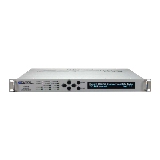
Overview Figure 1-1. CDM-625A Advanced Satellite Modem The CDM-625A Advanced Satellite Modem (Figure 1-1) is intended for both closed network and legacy Intelsat applications. It serves as the replacement for the CDM-625. It is 100% backwards compatible with the CDM-625, but incorporates new features and expansion capability. - Page 44 • A specialized version of the CDM-625A – the CDMER-625A – is also available. In addition to the features listed previously, this Environmentally Resistant (ER) version of the CDM-625A offers added protection in more aggressive operating environments that have a higher concentration of dust, sand and salt.
-
Page 45: Functional Description
CDM-625A Advanced Satellite Modem MN-CDM625A Introduction Revision 4 Functional Description The CDM-625A has two fundamentally different types of interface - IF and data: • The IF interface provides a bidirectional link with the satellite via the uplink and downlink equipment. •... -
Page 46: Features
1.3.3 Verification The CDM-625A includes many test modes and loopbacks for rapid verification of the correct functioning of the unit. Of particular note is the IF loopback, which permits you to perform a quick diagnostic test without having to disturb external cabling. During the loopback, all of the receive configuration parameters are temporarily changed to match those of the transmit side, and an internal RF switch connects the modulator output to the demodulator input. -
Page 47: Standard Data Interfaces
CDM-625A Advanced Satellite Modem MN-CDM625A Introduction Revision 4 Internet from Comtech EF Data’s Web site, via e-mail, or on CD, and can be transferred from an external client PC once connectivity has been established with the modem. 1.3.5 Standard Data Interfaces Chapter 3. -
Page 48: Table 1-1. Cdm-625A Optional Hardware And Accessories
PL-0021327 Modem Chassis – DC KT-0020683 DC to AC Conversion Kit for CDM-625A Base Modem KT-0020777 DC to AC Conversion Kit for CDM-625A with IP Packet Processor KT-0020692 DC Primary Power Supply: -48 VDC, w/req’d cables DC Power 3.3.3 PS-0020519... -
Page 49: Fully Accessible System Topology (Fast)
If you wish to upgrade the functionality of a unit at a later date, Comtech EF Data provides Fully Accessible System Topology (FAST), which permits the purchase and activation of options through special authorization codes. - Page 50 CDM-625A Advanced Satellite Modem MN-CDM625A Introduction Revision 4 Installation Option Description and Comments Method Data rate 18 kbps to 512 kbps FAST Data rate 18 kbps to 1 Mbps FAST Data rate 18 kbps to 2.5 Mbps FAST Data rate 18 kbps to 5.0 Mbps...
-
Page 51: Supporting Hardware And Software
CDM-625A. BUC Support: The CDM-625A incorporates an FSK serial link that can be activated on the Tx-IF port for the purpose of communicating with an FSK-capable “smart” BUC. This link is designed to be compatible with the Global VSAT Forum/ND SatCom specification. -
Page 52: Physical Features
CDM-625A Advanced Satellite Modem MN-CDM625A Introduction Revision 4 1.3.9 Physical Features 1.3.9.1 Dimensional Envelope All dimensions are in inches. Dimensions shown in parentheses are in metric units (mm). Figure 1-2. CDM-625A Dimensional Envelope 1–10... -
Page 53: Front Panel Features
Nested menus display Fluorescent 6.1.3 Display (VFD) all available options and prompt you to carry out a req’d action. These handles ease placement into and removal from a rack. Rack Handles Figure 1-3. CDM-625A Front Panel Features 1–11... -
Page 54: Rear Panel Features
(BOTTOM) Optional 48V DC Chassis (CEFD P/N PL-0021327) Figure 1-4. CDM-625A Rear Panel View Figure 1-4 shows the rear panel of the modem. External cables are attached to connectors on the rear panel of the CDM-625A. They comprise: Connection Group Name... -
Page 55: Summary Of Specifications
CDM-625A Advanced Satellite Modem MN-CDM625A Introduction Revision 4 Summary of Specifications 1.4.1 Modulator Modulation BPSK, QPSK, OQPSK, 8PSK, 8-QAM and 16-QAM Symbol rate range 18 ksps to 12.5 Msps Data rate range 18 kbps - 25 Mbps. See Section 1.4.7 Operating frequency 50 - 180 MHz (BNC connector) AND 950 - 2350 MHz (Type ‘N’... - Page 56 CDM-625A Advanced Satellite Modem MN-CDM625A Introduction Revision 4 FEC (cont.) Low Density Parity Check (LDPC) Codec (Optional plug-in card): Rate 1/2 BPSK/QPSK/OQPSK Rate 2/3 QPSK/OQPSK/8PSK/8-QAM Rate 3/4 QPSK/OQPSK/8PSK/8-QAM/16-QAM VersaFEC Codec (Optional plug-in card – short-block, low latency LDPC): Rate 0.488 BPSK (also 0.493 BPSK Ultra-Low-Latency) Rate 0.533, 0.631, 0.706, 0.803 QPSK (0.493, 0.654, 0.734 Ultra-Low-Latency)
- Page 57 CDM-625A Advanced Satellite Modem MN-CDM625A Introduction Revision 4 Output impedance 950-1950 MHz band: 50Ω, 19 dB minimum return loss (21 dB typical) 1950-2250 MHz band: 17dB minimum 50-180 MHz band: 50Ω, or 75Ω 16 dB minimum return loss (18 dB typical)
-
Page 58: Demodulator
CDM-625A Advanced Satellite Modem MN-CDM625A Introduction Revision 4 1.4.2 Demodulator Note: Data rate range, operating modes, descrambling, input impedance/return loss etc, as per Sect. 1.4.1 Modulator. Input power range, desired 950-2250 MHz band: carrier -130 + 10 (symbol rate) to -80 + 10... - Page 59 CDM-625A Advanced Satellite Modem MN-CDM625A Introduction Revision 4 LNB 10 MHz Reference On center conductor of L-Band input connector, selectable ON/OFF. Level: -3dBm ± 3 dB. Source: either Internal modem reference or External reference Performance: For phase noise, refer to L-Band modulator 10 MHz. Frequency stability same as the modulator 10 MHz reference.
- Page 60 CDM-625A Advanced Satellite Modem MN-CDM625A Introduction Revision 4 TURBO PRODUCT CODEC For BER=10 Rate – Guaranteed Eb/No (typical value in parentheses) Rate 21/44 (B, Q, OQ)* Rate 5/16 (B) Rate 21/44 B/Q/OQPSK BER=10 3.1 dB (2.9 dB) 2.7 dB (2.5dB)
- Page 61 CDM-625A Advanced Satellite Modem MN-CDM625A Introduction Revision 4 VersaFEC CODEC BER For BER=10 Rate – Guaranteed Eb/No (typical value in parentheses) QPSK Rate 0.533 QPSK Rate 0.631 QPSK Rate 0.706 QPSK Rate 0.803 QPSK (With two adjacent carriers, BER=10 2.3 dB (2.0 dB) 2.8 dB (2.5 dB)
- Page 62 CDM-625A Advanced Satellite Modem MN-CDM625A Introduction Revision 4 VersaFEC-2 Short Block For BER=10 Rate – Guaranteed Eb/No (typical value in parentheses) CODEC BER Rate 0.489 BPSK BPSK BER=10 2.6 dB (2.3 dB) (With two adjacent carriers, BER=10 3.2 dB (2.9 dB)
-
Page 63: Figure 1-5. Rx Carrier Level Vs. Symbol Rate - L-Band (950-2250 Mhz)
CDM-625A Advanced Satellite Modem MN-CDM625A Introduction Revision 4 Maximum Minimum 1000 10000 100000 Symbol Rate in ksps Figure 1-5. Rx Carrier Level vs. Symbol Rate – L-Band (950-2250 MHz) Maximum Minimum 1000 10000 100000 Symbol Rate in ksps Figure 1-6. Rx Carrier Level vs. Symbol Rate – IF Band (50-180 MHz) -
Page 64: Data Interfaces
CDM-625A Advanced Satellite Modem MN-CDM625A Introduction Revision 4 1.4.3 Data Interfaces Primary Data RS-422/EIA-530 DCE (Rates up to 14 Mbps) 25-pin D-sub (female) (4 selectable modes) (also supports X.21 DCE & DTE up to 2.048 Mbps and 8k ESC orderwire for IDR) V.35 DCE (Rates up to 14 Mbps) -
Page 65: Doubletalk Carrier- In-Carrier
CDM-625A Advanced Satellite Modem MN-CDM625A Introduction Revision 4 ® ® 1.4.5 DoubleTalk Carrier- in-Carrier (CnC) Requires the two links to share a common carrier frequency (Outbound and Inbound symbol rates do Operating Mode not have to be equal) BSPK/QPSK/8PSK/8-QAM: –7 dB to +11 dB (ratio of power spectral density, outbound interferer to... -
Page 66: Framing Summary
CDM-625A Advanced Satellite Modem MN-CDM625A Introduction Revision 4 1.4.6 Framing Summary Scrambling Available data rates Overhead Additional Reed- Framing Mode Overhead added and format components Solomon Overhead (see Note 1) 200/220 225/205 Basic ITU Transparent None All rates and formats... -
Page 67: Data Rate Ranges
CDM-625A Advanced Satellite Modem MN-CDM625A Introduction Revision 4 1.4.7 Data Rate Ranges UNFRAMED (NO REED SOLOMON) Lower Limit (kbps) Upper Limit (kbps) No FEC, BPSK 18.0 12500 No FEC, O/QPSK 36.0 25000.0 VITERBI, BPSK, 1/2 18.0 6250.0 VITERBI, O/QPSK, 1/2 18.0... - Page 68 CDM-625A Advanced Satellite Modem MN-CDM625A Introduction Revision 4 EDMAC, EDMAC-2, or EDMAC-3 (NO REED SOLOMON) Lower Limit (kbps) Upper Limit (kbps) No FEC, BPSK 18.0 12295.0 No FEC, O/QPSK 35.5 24590.1 VITERBI, BPSK, 1/2 18.0 6147.5 VITERBI, O/QPSK, 1/2 18.0 12295.0...
- Page 69 CDM-625A Advanced Satellite Modem MN-CDM625A Introduction Revision 4 IBS (NO REED SOLOMON) Lower Limit (kbps) Upper Limit (kbps) No FEC, BPSK 64.0 8448.0 No FEC, O/QPSK 64.0 8448.0 VITERBI, BPSK, 1/2 64.0 5859.3 VITERBI, O/QPSK, 1/2 64.0 8448.0 VITERBI, O/QPSK, 3/4 64.0...
- Page 70 CDM-625A Advanced Satellite Modem MN-CDM625A Introduction Revision 4 ESC++ (NO REED SOLOMON) Lower Limit (kbps) Upper Limit (kbps) No FEC, BPSK 64.0 12304.6 No FEC, O/QPSK 64.0 24609.3 VITERBI, BPSK, 1/2 64.0 5921.0 VITERBI, O/QPSK, 1/2 64.0 12304.6 VITERBI, O/QPSK, 3/4 64.0...
- Page 71 CDM-625A Advanced Satellite Modem MN-CDM625A Introduction Revision 4 VersaFEC (ANY MODE) Lower Limit (kbps) Upper Limit (kbps) VersaFEC BPSK Rate 0.488 18.0 5700.0 VersaFEC QPSK Rate 0.533 20.0 10000.0 VersaFEC QPSK Rate 0.631 23.0 10000.0 VersaFEC QPSK Rate 0.706 26.0 10000.0...
-
Page 72: Versafec Adaptive Coding And Modulation (Acm)
CDM-625A Advanced Satellite Modem MN-CDM625A Introduction Revision 4 1.4.8 VersaFEC Adaptive Coding and Modulation (ACM) 1.4.8.1 VersaFEC ACM Adaptive Coding and Modulation, using BPSK, QPSK, 8-QAM , 16-QAM and System type VersaFEC short-block LDPC coding – a total of 12 ModCods... -
Page 73: Versafec-2 Acm
CDM-625A Advanced Satellite Modem MN-CDM625A Introduction Revision 4 1.4.8.2 VersaFEC-2 ACM Adaptive Coding and Modulation, using BPSK, QPSK, 8-ARY, 16-ARY, 32-ARY and System type VersaFEC-2 Short-block and Long Block LDPC coding - total of 74 ModCods Symbol Rate Range 37 ksps to 12.5 Msps (Long) -
Page 74: Table 1-3. The Versafec-2 Modcod Set - Long Block
CDM-625A Advanced Satellite Modem MN-CDM625A Introduction Revision 4 Table 1-3. The VersaFEC-2 ModCod Set – Long Block Typical * Latency Min. Max. Min Sym Max Sym Spectral Block Es/No Code Data Rate, Data Rate, Rate, ACM Rate, ACM ModCod Modulation... -
Page 75: Table 1-4. The Versafec-2 Modcod Set - Short Block
CDM-625A Advanced Satellite Modem MN-CDM625A Introduction Revision 4 Table 1-4. The VersaFEC-2 ModCod Set – Short Block Typical * Latency Min. Max. Min Sym Max Sym Spectral Block Es/No Code Data Rate, Data Rate, Rate, ACM Rate, ACM ModCod Modulation... -
Page 76: Miscellaneous
CDM-625A Advanced Satellite Modem MN-CDM625A Introduction Revision 4 1.4.9 Miscellaneous Front Panel Tactile keypad, 6 keys (up, down, left, right, ENTER, CLEAR) Vacuum Fluorescent Display (blue) – two lines @ 40 characters/line Loopbacks Internal IF loopback, RF loopback, digital loopback, and inward/outward loopback... -
Page 77: Chapter 2. Installation
Unpack and Inspect the Shipment Figure 2-1. Unpack and Inspect the Shipment The CDM-625A Advanced Satellite Modem, its optional Installation and Operation Manual (otherwise available online at http://www.comtechefdata.com), and its power cord were packaged and shipped in a reusable cardboard carton containing protective foam spacing. -
Page 78: Install The Modem Into A Rack Enclosure
User-supplied screws to secure the front panel to the rack enclosure threaded front mounting rails; • Comtech EF Data’s optional KT/6228 (4”) or KT/6228 (10”) Rear-Mounting Support Brackets Kit (Figure 2-3). CAUTION – When mounting the modem into a rack enclosure: •... -
Page 79: Figure 2-2. Install The Modem Into A Rack Enclosure
Support. • The CDM-625A CANNOT have rack slides mounted to the sides of the chassis. Cooling fans and exhaust vents are provided here – air flow must not be impeded. Comtech EF Data recommends that an alternate method of support is provided within the rack, such as standard rack shelves or the optional Rear- Mounting Support Bracket Kit. -
Page 80: Install The Optional Rear-Mounting Support Brackets Kits
CDM-625A Advanced Satellite Modem MN-CDM625A Installation Revision 4 2.2.1 Install the Optional Rear-Mounting Support Brackets Kits Feature Description Back of modem Rack Enclosure Threaded Rear Mounting Rail (typical) Kit / Quantity Item CEFD P/N Description KT/6228-2 KT/6228-3 HW/10-32SHLDR Shoulder Screw, #10... -
Page 81: Configure The Modem
PINOUTS Once you verify correct operation via the Internal IF Loop test, use the front panel keypad to finalize your configuration as needed. Connect all external cables. If difficulties occur, contact Comtech EF Data Product Support for further assistance. 2–5... - Page 82 CDM-625A Advanced Satellite Modem MN-CDM625A Installation Revision 4 Notes: 2–6...
-
Page 83: Chapter 3. Rear Panel Connectors And Pinouts
(Type ‘N’ shown) Figure 3-1. Coaxial Connector Examples The types of coaxial cables used by Comtech EF Data are ‘BNC’, ‘TNC’, ‘N’, ‘F’, and ‘SMA’. Coaxial cables (plugs) and their mating connectors (jacks/sockets) are available in two coupling styles: Bayonet or Threaded. -
Page 84: Type 'Bnc
CDM-625A Advanced Satellite Modem MN-CDM625A Rear Panel Connectors and Pinouts Revision 4 • Threaded Coupling Style: The jack features external threads. The plug shell features internal threads, and has either a knurled outer surface to permit hand-tightening of the connection, or hex flats to accommodate torqued installation. -
Page 85: D-Subminiature Cable Connections
CDM-625A Advanced Satellite Modem MN-CDM625A Rear Panel Connectors and Pinouts Revision 4 3.1.2 D-Subminiature Cable Connections Type ‘D’ Connection Type Example Chassis Receptacles: Female (TOP) Male (BOTTOM) Type ‘D’ Cable with Jack Screws (female shown) Figure 3-2. D-Subminiature Connector Examples D-Subminiature connectors are also called Type ‘D’... -
Page 86: Cdm-625A Cabling Connections
15-pin Type ‘D’ male Form C Alarms (relay closures) PMSI 9-pin Type ‘D’ female Pre-Mapped Symbol Interface (CnC) 1:1 Control 9-pin Type ‘D’ female Connection to External 1:1 Controller External Reference BNC female Input/output Figure 3-3. CDM-625A Rear Panel View 3–4... -
Page 87: If Connection Group
CDM-625A Advanced Satellite Modem MN-CDM625A Rear Panel Connectors and Pinouts Revision 4 3.2.1 IF Connection Group WARNING! THERE MAY BE DC VOLTAGES, UP TO A MAXIMUM OF 48 VOLTS, PRESENT ON THE TYPE ‘N’ RX AND TX IF CONNECTORS. 3.2.1.1... -
Page 88: Terrestrial Data Connection Group
CDM-625A Advanced Satellite Modem MN-CDM625A Rear Panel Connectors and Pinouts Revision 4 3.2.2 Terrestrial Data Connection Group 3.2.2.1 Data Interface (DB-25F) The Data Interface connector is a 25-pin, Type ‘D’ female interface that conducts data input and output signals to and from the modem, and connects to customer’s terrestrial equipment, breakout panel, or... -
Page 89: Hssi Operation Via The Cic-60 Interface Adapter Module
For HSSI operation (Tx, Rx, or both), the optional CIC-60 Interface Adapter Module (Figure 3-4) may be purchased from Comtech EF Data to adapt the Data Interface 25-pin Type ‘D’ female connection to a standard 50-pin Type ‘HD’ HSSI (SCSI-II) female connection. -
Page 90: Table 3-2. Cic-60 Module Connector Pinouts - Hssi/Eia-613 Side
CDM-625A Advanced Satellite Modem MN-CDM625A Rear Panel Connectors and Pinouts Revision 4 Table 3-2. CIC-60 Module Connector Pinouts – HSSI/EIA-613 Side Table ordered by Signal Function Pin # Signal Function HSSI Signal EIA-613 Circuit Circuit Direction Comment (+, –) Signal Ground... -
Page 91: Connectors
CDM-625A Advanced Satellite Modem MN-CDM625A Rear Panel Connectors and Pinouts Revision 4 3.2.2.2 G.703 Connectors 3.2.2.2.1 Balanced G.703 (DB-9F) The Balanced G.703 connector is a 9-pin Type ‘D’ female connector. It is used for single port G.703, D&I or D&I++. When used with Quad E1 operations, this connector serves Ports 1 and 2 of the Quad E1 interface. -
Page 92: Ca-0000163 Adapter Cable
If all four ports of Quad E1 are needed, the user will need to obtain a quantity of (2X) of any adapter option. For Quad E1 operation, optional Comtech EF Data cabling accessories may be purchased from Comtech EF Data to adapt the Balanced G.703 or Auxiliary G.703 connectors as follows: Figure CEFD Part No. -
Page 93: Ca-0000164 Adapter Cable
CDM-625A Advanced Satellite Modem MN-CDM625A Rear Panel Connectors and Pinouts Revision 4 3.2.2.2.3.2 CA-0000164 Adapter Cable Figure 3-6. CA-0000164 Adapter Cable (DB-9M (2X) RJ-48F) Table 3-6. CA-0000164 Connector Pinouts Table ordered by Signal Function Connector Twisted Signal Function Pair Port 1 or 3 Tx In (+) ––... -
Page 94: Kt-0000122/Kt-0020570 Quad E1 Balanced/Unbalanced Adapter Cable Kits
CDM-625A Advanced Satellite Modem MN-CDM625A Rear Panel Connectors and Pinouts Revision 4 3.2.2.2.3.3 KT-0000122/KT-0020570 Quad E1 Balanced/Unbalanced Adapter Cable Kits Quad E1 Balanced/Unbalanced Adapter Kits Kit / Quantity CEFD Part No. Description KT-0000122 KT-0020570 –– CA-0000347 Y-Cable Assembly, 6”, DB-9M 2X RJ-48 Male (See Table 3-7) ––... -
Page 95: Unbal G.703 / Asi - Out (Ido), In (Ddi)
CDM-625A Advanced Satellite Modem MN-CDM625A Rear Panel Connectors and Pinouts Revision 4 3.2.2.2.4 Unbal G.703 / ASI – Out (IDO), In (DDI) Connector Type Description Direction G.703 Unbalanced Rx (IDO) / ASI G.703 Unbalanced Tx (DDI) / ASI 3.2.2.2.5 G.703 IDI (Insert Data In), DDO (Drop Data Out) -
Page 96: Esc (Db-9F)
CDM-625A Advanced Satellite Modem MN-CDM625A Rear Panel Connectors and Pinouts Revision 4 3.2.2.5 ESC (DB-9F) The ESC (Engineering Service Channel) port is a 9-pin Type ‘D’ female connector. Table 3-9. ESC Connector Pinouts (R>L) Asynchronous Synchronous Pin # –– EIA-232 Tx Clock Out EIA-485 Rx Data A Out ––... -
Page 97: Alarms (Db-15M)
CDM-625A Advanced Satellite Modem MN-CDM625A Rear Panel Connectors and Pinouts Revision 4 3.2.3.2 Alarms (DB-15M) Unit alarms are provided on this 15-pin Type ‘D’ male connector. Table 3-11. Alarm Interface Connector Pinouts (L>R) Name Signal Function Pin # Ground EXT-OFF... -
Page 98: 1:1 Control (Db-9F)
CDM-625A Advanced Satellite Modem MN-CDM625A Rear Panel Connectors and Pinouts Revision 4 3.2.3.4 1:1 Control (DB-9F) The 1:1 Control connector is intended only for connection to a CRS-170A or CRS-180 Redundancy Switch. The 1:1 Control connector is a 9-pin Type ‘D’ female connector. -
Page 99: Cdm-625A Ground And Power Connections
(TOP) Standard AC Chassis (CEFD P/N PL-0021325) (BOTTOM) Optional 48V DC Chassis (CEFD P/N PL-0021327) Figure 3-8. CDM-625A Chassis Ground Interface Use the #10-32 stud, located adjacent to the power interface, for connecting a common chassis ground among equipment. -
Page 100: Standard 100V/240V Alternating Current (Ac) Power Interface
T4A ( 250V AC operation) Figure 3-9. CDM-625A Standard AC Chassis (CEFD P/N PL/12587-1) 3.3.2.1 AC Operation – CDM-625A Accessories Contact Comtech EF Data Product Support to purchase any of these available accessories: CEFD P/N Description KT-0020703 AC to 24V DC Conversion Kit... -
Page 101: Ac Operation - Apply Power
3.3.2.3 AC Operation – Replace the Fuses For AC operation the CDM-625A uses two common 5mm x 20mm Slow-blow fuses – one each for line and neutral connections. The fuses are contained within a fuse holder that is press-fit into the body of the IEC power module (located on the rear panel, Figure 3-11). -
Page 102: Optional 48V Direct Current (Dc) Power Interface
43 – 60 VDC Nominal Input Voltage 36 – 60 VDC Maximum Connector Type Terminal Block (2X) 5mm x 20mm Slow-blow type fuses: Fuse Protection Modem Fuse: 3Amp/250Volts BUC Fuse: 6.3 Amp/250 Volts Figure 3-12. CDM-625A Optional DC Chassis (CEFD P/N PL-0021327) 3–20... -
Page 103: Optional Dc Operation - Cdm-625A Accessories
Rear Panel Connectors and Pinouts Revision 4 3.3.3.1 Optional DC Operation – CDM-625A Accessories Contact Comtech EF Data Product Support to purchase any of these available accessories: CEFD P/N Description KT-0020683 DC to AC Conversion Kit for CDM-625A Base Modem... -
Page 104: Optional Dc Operation - Replace The Fuses
Revision 4 3.3.3.3 Optional DC Operation – Replace the Fuses For DC operation the CDM-625A requires two different fuses that are contained within the individual screw-in receptacles below the terminal block (located on the rear panel, Figure 3-14). Figure 3-14. Replace the CDM-625A Optional DC Chassis Fuses... -
Page 105: Chapter 4. Updating Firmware
If a firmware update is needed, once Ethernet connectivity has been established with the unit, you can download the update archive file from the Comtech EF Data Web site (www.comtechefdata.com), or obtain it through e-mail from Comtech EF Data Product Support. -
Page 106: About Firmware Files, Naming, Versions, And Archive Formats
Revision 4 About Firmware Files, Naming, Versions, and Archive Formats Comtech EF Data’s Web site catalogues its firmware update files by product type (e.g., modem, converter, etc.) and specific model/optional configuration. For example, the base modem bulk firmware download hyperlink appears as F0020731*_V### (where ‘###’ indicates the firmware version number, and ‘*’... -
Page 107: Ethernet Ftp Upload Procedure
Web browser (e.g., Internet Explorer); and a terminal emulator program (e.g., Tera Term or HyperTerminal). • A 9-pin serial cable and a standard CAT5 Ethernet cable to connect the CDM-625A to the User PC. A. Use the 9-pin serial cable to connect the CDM-625A ‘Remote Control’ port to a serial port on the User PC. - Page 108 Ethernet IP Address/Range: 192.168.001.002/24 () Using the CDM-625A HTTP Interface (via the User PC Web Browser) – this assumes that you have already noted the Traffic/Management IP Address, which was previously required to open the CDM-625A HTTP Interface: •...
- Page 109 CDM-625A Advanced Satellite Modem MN-CDM625A Updating Firmware Revision 4 Using the CDM-625A Serial Remote Interface (via the User PC / terminal emulator program): • Firmware Info – Use the <0/SWR? (condensed) or <0/FRW? (detailed) remote query. • Ethernet Traffic/Management IP Address – Use the <0/IPA? remote query.
- Page 110 CDM-625A Advanced Satellite Modem MN-CDM625A Updating Firmware Revision 4 C. Use the ‘Run’ and ‘Browse’ windows to create and rename the temporary folder. • Select [Start] on the Windows taskbar, and then click the Run... icon. This opens the ‘Run’ window.
-
Page 111: Download And Extract The Firmware Update
4.3.2 Download and Extract the Firmware Update 1) First, download the firmware update file from the Comtech EF Data Web site: A. Go online to www.comtechefdata.com. B. On the Main page – under Support Information or the Support tab, select the Software Downloads hyperlink. - Page 112 CDM-625A Advanced Satellite Modem MN-CDM625A Updating Firmware Revision 4 For the Base Modem update, a minimum of two files should be extracted: • FW-0020731*_CDM-625A_#.#.#.bin – The base modem bulk image file (where ‘*’ is the revision letter). • CDM625A_ReleaseNotes_v#.#.#.pdf (or a variation of this filename, where “###”...
-
Page 113: Perform The Ethernet Ftp Upload Procedure
You may alternately use the CDM-625A HTTP Interface ‘Admin | Utilities’ page, as shown in this example: For either method, the response should confirm whether the unit is properly connected and communicating. 2) Use Command-line to transfer (FTP) the files from the User PC to the CDM-625A: 4–9... - Page 114 MN-CDM625A Updating Firmware Revision 4 A. Type "ftp xxx.xxx.xxx.xxx" (where ‘xxx.xxx.xxx.xxx’ is the CDM-625A Ethernet Traffic/Management IP Address). B. If the optional IP Packet Processor is installed and enabled, enter the User Name and Password when prompted. The default User Name and Password is “comtech”.
- Page 115 If you are a Base Modem user, the CDM-625A is now operating with its latest firmware and you may skip to Step 6. However, if you are running a CDM-625A with the optional IP Packet Processor installed, do NOT reboot at this time – once you have uploaded the base modem firmware you must proceed to the next step (Step 4) to upload the IP Packet Processor firmware.
- Page 116 PC-to-Modem IP Packet Processor firmware FTP file transfer was successful. 6) Use the modem front panel menus, or the CDM-625A HTTP Interface ‘Admin | Firmware | Base Modem’ or, as needed, ‘Admin | Firmware | Packet Processor’ page to select the desired firmware image to boot from: A.
- Page 117 PktP, VFEC-2 present Ver1.4.1 You will need to log in to a new Web session at this time. The CDM-625A HTTP Interface ‘Home’ page will serve to verify that the new firmware version is active, as shown in this example: The CDM-625A is now operating with its latest firmware.
- Page 118 CDM-625A Advanced Satellite Modem MN-CDM625A Updating Firmware Revision 4 Notes: 4–14...
-
Page 119: Chapter 5. Fast Activation Procedure
If you wish to upgrade the functionality of a unit at a later date, Comtech EF Data provides Fully Accessible System Topology (FAST), which permits the purchase and activation of options through special authorization codes. -
Page 120: Fast Activation Procedure
See Chapter 6. FRONT PANEL OPERATION for complete information about using this interface. 1) Before you contact Comtech EF Data Product Support to order FAST feature upgrades, you must retrieve the modem’s motherboard serial number: A. From the front panel main menu, SELECT: FAST, and then press ENTER. - Page 121 C. Obtain the invoice, the register-specific 20-digit FAST Access Code(s), and the FAST option activation instructions. When a FAST Access Code is obtained from Comtech EF Data, it will be for a specific option register . The FAST options are linked to two option registers: •...
-
Page 122: Fast Activation Using The Cdm-625A Http (Web Server) Interface
Figure 5-1. CDM-625A HTTP Interface – ‘Admin | FAST’ page Use the CDM-625A HTTP (Web Server) Interface ‘Admin | FAST’ page (Figure 5-1) for complete management of FAST Features. This page provides scrollable list boxes that display the availability and activation status for all FAST options. - Page 123 C. Obtain the invoice, the register-specific 20-digit FAST Access Code(s), and the FAST option activation instructions. When a FAST Access Code is obtained from Comtech EF Data, it will be for a specific option register . The FAST options are linked to two option registers: •...
- Page 124 CDM-625A Advanced Satellite Modem MN-CDM625A FAST Activation Procedure Revision 4 Notes: 5–6...
-
Page 125: Chapter 6. Front Panel Operation
The VFD is an active display showing two lines of 40 characters Vacuum each. It produces a blue light with adjustable brightness. Nested Fluorescent 6.1.3 menus (Figure 6-2) display all available options and prompt you to Display (VFD) carry out a required action. Figure 6-1. CDM-625A Front Panel Features 6–1... -
Page 126: Led Indicators
CDM-625A Advanced Satellite Modem MN-CDM625A Front Panel Operation Revision 4 6.1.1 LED Indicators In general, the Alarm relay state reflects the state of the Front Panel LEDs. For example, if the Unit Status LED is red, the Unit Alarm relay is active, etc. The sole exception is the Transmit Traffic relay –... -
Page 127: Keypad
CDM-625A Advanced Satellite Modem MN-CDM625A Front Panel Operation Revision 4 State Function BUC or LNB or CSAT or KST fault detected ODU FAULT Flashing Communication fault with BUC or CSAT or KST BUC or LNB or CSAT or KST no fault detected... -
Page 128: Vacuum Fluorescent Display (Vfd)
Front Panel Operation Revision 4 6.1.3 Vacuum Fluorescent Display (VFD) The CDM-625A features a Vacuum Fluorescent Display (VFD). The VFD is an active display showing two lines of 40 characters each. It produces a blue light with adjustable brightness. Compared to a Liquid Crystal Display (LCD), the VCD provides superior viewing characteristics and does not suffer problems of viewing angle or contrast. - Page 129 You may configure this mode via the front panel (SELECT: UtilityEm) or by remote control (remote command EMU=). When you select emulation, the CDM-625A opening screen displays this mode of operation, as this example shows:...
-
Page 130: Select: (Main) Menu
Utility FAST () Figure 6-2 shows the hierarchal structure of the CDM-625A principle menu tree from the SELECT: menu on down. Press ENTER or CLEAR to immediately access the SELECT: menu screen from the opening screen. From any nested menu, press CLEAR repeatedly until this screen reappears. -
Page 131: Figure 6-2. Cdm-625A Principle Menu Tree (Fw Ver. 1.4.1)
CDM-625A Advanced Satellite Modem MN-CDM625A Front Panel Operation Revision 4 Figure 6-2. CDM-625A Principle Menu Tree (FW Ver. 1.4.1) 6–7... -
Page 132: Select: Config (Configuration) Menu Branch
CDM-625A Advanced Satellite Modem MN-CDM625A Front Panel Operation Revision 4 6.2.1 SELECT: CONFIG (Configuration) Menu Branch CONFIG: Mode Clocks D&I/ACM EDMAC Misc Mask Remote () Use the ◄ ► arrow keys to select a submenu. Press ENTER. Valid selections are: Submenu Sect. -
Page 133: Config: All
CDM-625A Advanced Satellite Modem MN-CDM625A Front Panel Operation Revision 4 6.2.1.1 CONFIG: All All = Stop (Stop, Start) Use this menu to configure the unit on a step-by-step basis. Every available configuration menu displays in succession. First, use the arrow keys to select Stop or Start. Press ENTER to execute. -
Page 134: Config: Mode
CDM-625A Advanced Satellite Modem MN-CDM625A Front Panel Operation Revision 4 6.2.1.2 CONFIG: Mode MODE is a key parameter when configuring the modem. To simplify the menu selections, you must first determine the INTERFACE and FRAMING type for both Transmit and Receive. Once these have been selected, you are presented only with menu selections that are applicable to those particular modes. - Page 135 D&I (FAST option) G.703 interfaces to enable the modem to transmit or receive fractional parts of a T1 or E1 data stream. D&I++ is a Comtech EF Data proprietary framing – it is a closed- D&I++ (FAST option) • network frame structure similar to D&I, but which permits AUPC and EDMAC.
-
Page 136: Config: Tx
CDM-625A Advanced Satellite Modem MN-CDM625A Front Panel Operation Revision 4 6.2.1.3 CONFIG: Tx Tx-IF Freq Power FEC Mod Data Scrambler (Data 00192.000kbps, 00131.657ksps) () On the top line – Use the ◄ ►arrow keys to select a parameter. Press ENTER. -
Page 137: Config: Tx Freq (Frequency)
CDM-625A Advanced Satellite Modem MN-CDM625A Front Panel Operation Revision 4 • Txα (Tx Alpha Filter Rolloff Factor) – Use the arrow keys to select the Txα. Press ▲▼ ENTER. Valid settings are: Txα (Tx Alpha rollout Factor) (%) Default 0.05, 0.10, 0.15, 0.25 0.35... - Page 138 CDM-625A Advanced Satellite Modem MN-CDM625A Front Panel Operation Revision 4 6.2.1.3.3 CONFIG: Tx Power Output Power: Mode= Manual (Manual,AUPC) Level= –20.0 dBm () Use the ◄ ► arrow keys to select the Output Power Mode (top line) or to edit the Output Power Level (bottom line).
- Page 139 CDM-625A Advanced Satellite Modem MN-CDM625A Front Panel Operation Revision 4 CONFIG: Tx Power Mode AUPC Target-EbNo-Range Minimum EbNo of Remote Modem = 5.0dB Max Permitted Power Increase = 9dB () On the top line – Edit the Target Eb/No of the remote modem by using the ◄...
-
Page 140: Config: Tx Power
CDM-625A Advanced Satellite Modem MN-CDM625A Front Panel Operation Revision 4 CONFIG: Tx Power Mode AUPC Alarm-Action (IP-ACM or V2-ACM Mode) Tx-Alarm: Max Power (MaxPwr,MinMCod,None) Rem Demod Unlock Act=NomPwr(Nom,Max,Hold) On the top line – Use the ▲▼ arrow keys to select the alarm action that occurs if the AUPC causes the maximum output power level to be reached. -
Page 141: Config: Tx Fec
CDM-625A Advanced Satellite Modem MN-CDM625A Front Panel Operation Revision 4 6.2.1.3.4 CONFIG: Tx FEC Enc=Vit (Vit,Seq,TCM,TPC,LDPC,VFEC,ULL) Reed-Solomon=On (Off, On) () Use the ◄ ► arrow keys to select Encoder or Reed-Solomon (or Diff Encoder – see Note 1 below). Press ENTER. -
Page 142: Config: Tx Mod (Modulation)
CDM-625A Advanced Satellite Modem MN-CDM625A Front Panel Operation Revision 4 Otherwise, when Diff Encoder is selectable on the bottom line: CONFIG: Tx FEC Diff Encoder On Enc=None(Vit,Seq,TCM,TPC,LDPC,VFEC,ULL) Diff Encoder=On (Off,On) () Use the arrow keys to select the Diff Encoder as On or Off. Press ENTER: ▲▼... - Page 143 CDM-625A Advanced Satellite Modem MN-CDM625A Front Panel Operation Revision 4 Encoder Type Modulation Type FEC Rate Choice BPSK Fixed at 0.489 0.489, 0.537, 0.586, 0.611, 0.635, QPSK 0.660, 0.684, 0.733 VF2L (VersaFEC-2 Long Block) 0.521, 0.537, 0.562, 0.586, 0.611, 8-ARY 0.635, 0.770, 0.684, 0.708, 0.733...
-
Page 144: Config: Tx Data
CDM-625A Advanced Satellite Modem MN-CDM625A Front Panel Operation Revision 4 6.2.1.3.6 CONFIG: Tx Data Tx Data Rate Tx Sub-Mux () Use the ◄ ► arrow keys to select Tx Data Rate or Tx Sub-Mux. Press ENTER. When Tx Sub-Mux is ON, this menu provides read-only IP Info Rate information on the bottom... -
Page 145: Config: Tx Symb (Ip-Acm Or V2-Acm Modes Only)
CDM-625A Advanced Satellite Modem MN-CDM625A Front Panel Operation Revision 4 CONFIG: Tx Tx Data Tx Sub-Mux Tx Sub-Mux = Off (Off, On) Ratio = 1/9 (IP/Synchronous) () Use the arrow keys to select the desired ratio. Press ENTER. There are a total of 34 ratio ▲▼... - Page 146 CDM-625A Advanced Satellite Modem MN-CDM625A Front Panel Operation Revision 4 The modem automatically selects the actual scrambler used for Normal, depending on the exact operating mode: • If framing = IBS/D&I, the IESS-309 scrambler is used. • If Reed-Solomon is on but IBS/D&I is off, its frame synchronous scrambler is used per IESS-310, App.
-
Page 147: Config: Rx
CDM-625A Advanced Satellite Modem MN-CDM625A Front Panel Operation Revision 4 6.2.1.4 CONFIG: Rx RxIF Freq FEC Demod Data Descram Eq EbNo (Data 02048.000kbps,02184.533ksps) () On the top line – Use the ◄ ► arrow keys to select a parameter. Press ENTER. -
Page 148: Config: Rx Freq (Frequency)
CDM-625A Advanced Satellite Modem MN-CDM625A Front Panel Operation Revision 4 demodulator automatically synchronizes to either the normal time-ordering of bits FEC codeword pairs, or the inverted ordering used by certain other manufacturers. • Rxα (Rx Alpha Filter Rolloff Factor) – Use the arrow keys to select the Txα. -
Page 149: Config: Rx Fec
CDM-625A Advanced Satellite Modem MN-CDM625A Front Panel Operation Revision 4 6.2.1.4.3 CONFIG: Rx FEC Dec=Vit (Vit,Seq,TCM,TPC,LDPC,VFEC,ULL) Reed-Solomon=Off (Off,On) () Use the ◄ ► arrow keys to select Dec (Decoder) or Reed-Solomon (or Diff Encoder – see Note 1 below). Press ENTER. -
Page 150: Config: Rx Demod (Demodulation)
CDM-625A Advanced Satellite Modem MN-CDM625A Front Panel Operation Revision 4 CONFIG: Rx FEC Diff Encoder On When you select Differential Decoding as OFF, there is no way for the modem to resolve the phase ambiguities associated with PSK modulations. For BPSK there is a 50% chance that the polarity of the data will be correct. -
Page 151: Config: Rx Data
CDM-625A Advanced Satellite Modem MN-CDM625A Front Panel Operation Revision 4 Decoder Type Modulation Type FEC Rate Choice VF2L or VF2S (cont.) 0.521, 0.537, 0.562, 0.586, 0.611, 8-ARY 0.635, 0.770, 0.684, 0.708, 0.733 0.586, 0.611, 0.635, 0.660, 0.684, 16-ARY 0.708, 0.733, 0.757, 0.782 0.660, 0.684, 0.708, 0.733, 0.757,... - Page 152 CDM-625A Advanced Satellite Modem MN-CDM625A Front Panel Operation Revision 4 Use the top line to edit the Rx Data Rate. The bottom line permits selection of the Data Inversion or the Clock Inversion features (added for compatibility with certain older equipment).
-
Page 153: Config: Rx Symb (Ip-Acm Or V2-Acm Modes Only)
When framing = IBS/D&I, the IESS-309 scrambler is used. • When Reed-Solomon is ON but IBS/D&I is OFF, its frame synchronous scrambler is used per IESS-310, App. H. An exception to this is legacy Comtech EF Data Reed-Solomon, which instead uses a proprietary modified V.35 scrambler. •... -
Page 154: Config: Rx Eq (Equalizer)
CDM-625A Advanced Satellite Modem MN-CDM625A Front Panel Operation Revision 4 When you select IESS, the default ITU V.35 scrambler specified in IESS-315 takes priority over all “normal” scramblers and is used instead. Therefore, for many operating modes, the two scrambler selections are redundant. -
Page 155: Config: Clocks
CDM-625A Advanced Satellite Modem MN-CDM625A Front Panel Operation Revision 4 Edit the SNR Alarm Point by using the ◄ ► arrow keys to select a digit, and then using the ▲▼ arrow keys to change that digit. The allowable range is from 00.1 to 16.0 dB. Press ENTER. - Page 156 CDM-625A Advanced Satellite Modem MN-CDM625A Front Panel Operation Revision 4 6.2.1.5.2 CONFIG: Clocks Rx Buffer/Clock Clk=Rx-Sat (Rx-Sat,TxTerr,Int(SCT),Ins) Buffer-Size = 00016bytes(00002ms) CENTER ◄ ► arrow keys to set the Rx Clock (top line) or the Buffer-Size (bottom line). Use the On the top line –...
-
Page 157: Config: Clocks Clk-Ext (G.703 Clock Extension)
(T1, E1-B, E1-U) () When you select TxLock as the mode, the transmit timing of the CDM-625A locks to the timing presented of the interface type selected here. When you select RxEnable as the mode, the CDM-625A generates a timing signal of the interface type selected here. -
Page 158: Config: Clocks Freq-Ref
CDM-625A Advanced Satellite Modem MN-CDM625A Front Panel Operation Revision 4 6.2.1.5.4 CONFIG: Clocks Freq-Ref Frequency Reference: Internal (Internal(with O/P),1,2,5,10MHz) () Use the arrow keys to select one of the two internal reference modes – Internal and ▲▼ Internal (with Output) – and then press ENTER. -
Page 159: Config: D&I (Drop & Insert)
CDM-625A Advanced Satellite Modem MN-CDM625A Front Panel Operation Revision 4 6.2.1.6 CONFIG: D&I (Drop & Insert) • Sect. 6.2.1.2 CONFIG: Mode • Appendix E. CLOCK MODES DROP & INSERT (D&I). 1) Drop & Insert operation is a FAST option. 2) D&I (Drop & Insert) is not available when you select either ACM mode. - Page 160 CDM-625A Advanced Satellite Modem MN-CDM625A Front Panel Operation Revision 4 CONFIG: D&I Drp-Type or Ins-Type Appendix E.6 Frame Formats The available Frame Format types for Drop or Insert are: Frame Format (Type) Description T1-D4 T1 D4 Framing T1-ESF T1 Extended Super Frame Framing...
-
Page 161: Config: Quad D&I (Qdi) (Qdi, Framed Qdi Framing Mode)
CDM-625A Advanced Satellite Modem MN-CDM625A Front Panel Operation Revision 4 6.2.1.6.2 CONFIG: Quad D&I (QDI) (QDI, Framed QDI Framing Mode) With QDI or Framed QDI set as the framing mode, the D&I menu branch displays Quad D&I operation as follows: Quad D&I (QDI):... - Page 162 CDM-625A Advanced Satellite Modem MN-CDM625A Front Panel Operation Revision 4 Each display is limited to eight channels. The ‘>’ character displays at the top line, right-hand side of the Drop or Insert screen to indicate that there are channels beyond Channel 8 available ◄...
-
Page 163: Config: Acm (Adaptive Coding And Modulation) (Ip-Acm Or V2-Acm Modes Only)
CDM-625A Advanced Satellite Modem MN-CDM625A Front Panel Operation Revision 4 6.2.1.7 CONFIG: ACM (Adaptive Coding and Modulation) (IP-ACM or V2-ACM Modes Only) Appendix M. ADAPTIVE CODING AND MODULATION (ACM) ACM Config: Min/Max-ModCod Unlock-Action Target-SNR-Margin () Use the ◄ ► arrow keys to select a parameter. Press ENTER. -
Page 164: Config: Acm Unlock-Action
CDM-625A Advanced Satellite Modem MN-CDM625A Front Panel Operation Revision 4 6.2.1.7.2 CONFIG: ACM Unlock-Action If using IP-ACM Mode: When distant-end demod loses lock: Go to min Tx ModCod (Maintain,Min) () Use this submenu to establish the desired action when the remote demod loses lock. This is important, as the ACM system depends on the feedback of the SNR metric from the remote demod to determine the optimum ModCod. -
Page 165: Config: Cnc
CDM-625A Advanced Satellite Modem MN-CDM625A Front Panel Operation Revision 4 6.2.1.8 CONFIG: CnC CnC operation requires that you purchase one of several available FAST options to provide capability to a maximum of 25Mbps. 1) Appendix F. DoubleTalk Carrier-in-Carrier OPTION 2) For more information about purchasing FAST options: •... -
Page 166: Config: Cnc Search-Delay
CDM-625A Advanced Satellite Modem MN-CDM625A Front Panel Operation Revision 4 • Below 64 ksymbols/sec: ±1 to ±(Rs/2) kHz, where: Rs=symbol rate in ksymbols/sec • Between 64 and 389 ksymbols/sec: ± 1 up to a maximum of ± 32kHz • Above 389 ksymbols/sec: ±1 to ± (0.1Rs) kHz, up to a maximum of ± 200 kHz This range is pre-calculated and displayed in parentheses for reference. -
Page 167: Config: Cnc Pmsi-Control
To use this mode of operation, you must connect the appropriate cable to the PMSI connector on the rear panel of each modem: • For 1:N multi-drop applications – Use Comtech EF Data cable P/N CA-0000275; For 1:1 applications – Use Comtech EF Data cable P/N CA-0000276. •... -
Page 168: Config: Edmac
CDM-625A Advanced Satellite Modem MN-CDM625A Front Panel Operation Revision 4 6.2.1.9 CONFIG: EDMAC Appendix H. EDMAC CHANNEL Embedded Distant-end Monitor And Control (EDMAC) is a Comtech-proprietary framing that permits communication access to the distant-end modem. Without the proper active framing mode, the menu appears as follows:... -
Page 169: Config: Misc
CDM-625A Advanced Satellite Modem MN-CDM625A Front Panel Operation Revision 4 6.2.1.10 CONFIG: Misc Misc: G.703-LineCode IDR-ESC HSSI Audio-Vol HiRateESC WarmUp Stats MEO () Use the ◄ ► arrow keys to select a parameter. Press ENTER. 6.2.1.10.1 CONFIG: Misc G.703-LineCode (Ternary Code) This menu is functional only when the Data Interface Type is G.703. -
Page 170: Config: Misc Hssi
CDM-625A Advanced Satellite Modem MN-CDM625A Front Panel Operation Revision 4 6.2.1.10.3 CONFIG: Misc HSSI This menu is functional only when the Data Interface Type is HSSI. HSSI handshake control: (2 options) TA-> CA loop () Use the arrow keys to select HSSI handshake control as TA -> CA loop, RR cntl CA, or TA ▲▼... -
Page 171: Config: Misc Hirateesc
CDM-625A Advanced Satellite Modem MN-CDM625A Front Panel Operation Revision 4 6.2.1.10.6 CONFIG: Misc HiRateESC High-Rate-ESC=Off (Off,On) RS-232 2400 baud DataParityStop=8N1 () The ESC (Engineering Service Channel) is determined by the framing type (IBS, D&I, or ESC++) selected under CONFIG: Mode. The High Rate IBS (Engineering Service Channel) requires the Open Network FAST option. -
Page 172: Config: Misc Warm-Up
(MEO requires ACM, PaP, and no Cnc) MEO is non-functional when CnC is enabled. CDM-625A Advanced Satellite Modems are configurable for continuous pairing as Primary and non-Primary Modems in an Antenna Handover System when the MEO (Medium Earth Orbit) feature is enabled. - Page 173 CDM-625A Advanced Satellite Modem MN-CDM625A Front Panel Operation Revision 4 Ethernet data traffic is transmitted and received via the Primary and Non-Primary CDM-625’s four 10/100 Ethernet ports. The Antenna Handover signal received from the user-provided IF/RF switch determines which modem is the ONLINE or OFFLINE unit: •...
-
Page 174: Config: Mask
CDM-625A Advanced Satellite Modem MN-CDM625A Front Panel Operation Revision 4 • Use the arrow keys to set the Antenna Handover switching mode as Manual or ▲▼ Auto. • Set the Communication Port Address for this unit by using the ◄ ►... -
Page 175: Config: Mask Rxif
CDM-625A Advanced Satellite Modem MN-CDM625A Front Panel Operation Revision 4 When you select the Buffer Slip Alarm as Active, the modem generates a Buffer Slip Rx Fault whenever the Rx circuitry senses that the buffer is either underflowing or overflowing. Press ENTER. -
Page 176: Config: Mask Txsat (Satellite Tx Alarms)
▲▼ to set that alarm as Active or Masked. Press ENTER. 6.2.1.11.9 CONFIG: Mask BUC Chapter 10. CDM-625A ODU (TRANSCEIVER, BUC, LNB) OPERATION BUC alarm = Active (Active,Mask) Attach to Tx alarm = No (Yes,No)() When L-Band is in use, you may include a Block Up Converter (BUC) in the operating system. You may monitor and control a ‘smart’... -
Page 177: Config: Mask Lnb
For a modem in a 1:1 redundancy setup, you must customize the fault indications for the physical setup. 6.2.1.11.10 CONFIG: Mask LNB Chapter 10. CDM-625A ODU (TRANSCEIVER, BUC, LNB) OPERATION LNB alarm = Active (Active,Mask) Attach to Rx alarm = No (Yes,No)() -
Page 178: Config: Remote (Remote Control)
CDM-625A Advanced Satellite Modem MN-CDM625A Front Panel Operation Revision 4 6.2.1.12 CONFIG: Remote (Remote Control) Remote Control=Local (Local,Serial remote,Ethernet) () Use the arrow keys to select Local, Serial remote, or Ethernet. Press ENTER. ▲▼ When you select Local, you are not permitted to reconfigure the modem via Serial Remote or Ethernet, although remote monitoring is permissible. -
Page 179: Config: Ip
CDM-625A Advanced Satellite Modem MN-CDM625A Front Panel Operation Revision 4 6.2.1.13 CONFIG: IP IP Config: Addresses SNMP Setup PortMonitor AccessList PktP-Enable() arrow keys to select a parameter. PktP-Enable displays only when you install the Use the ◄ ► the optional IP Packet Processor card. -
Page 180: Config: Ip Snmp
CDM-625A Advanced Satellite Modem MN-CDM625A Front Panel Operation Revision 4 6.2.1.13.2 CONFIG: IP SNMP SNMP: Communities Traps () Use the ◄ ► arrow keys to select Communities or Traps. Press ENTER. CONFIG: IP SNMP Communities SNMP Communities:... - Page 181 CDM-625A Advanced Satellite Modem MN-CDM625A Front Panel Operation Revision 4 CONFIG: IP SNMP Traps Traps: Community Version IP-Addr#1 IP-Addr#2 () ◄ ► arrow keys to select a parameter. Press ENTER. Use the CONFIG: IP SNMP Traps Community...
-
Page 182: Config: Ip Setup
CDM-625A Advanced Satellite Modem MN-CDM625A Front Panel Operation Revision 4 6.2.1.13.3 CONFIG: IP Setup IP Setup: Mode PerPortCnfg DDMgmtPt MAC-Lrng Rad VLAN QoS Stats FrmSize () Use the ◄ ► arrow keys to select a parameter. Press ENTER. 6.2.1.13.3.1 CONFIG: IP IP Setup: Mode Working Mode: Router Point to Point (ManagedSwitch,R-PtoP, R-MPHub,R-MPRm)() -
Page 183: Config: Ip Setup: Perportcnfg
CDM-625A Advanced Satellite Modem MN-CDM625A Front Panel Operation Revision 4 6.2.1.13.3.3 CONFIG: IP Setup: PerPortCnfg Per-Port-Config: Port1 Port2 Port3 Port4 () Use the ◄ ► arrow keys to select Port1 through Port4. Press ENTER. CONFIG: IP IP Setup: PerPortCnfg Port#... - Page 184 CDM-625A Advanced Satellite Modem MN-CDM625A Front Panel Operation Revision 4 When the rate at which packets received from the LAN side approaches the maximum rate the modem can handle, the FIFO acts as an elastic buffer that will store a packet, or packets, on a temporary basis.
-
Page 185: Config: Ip Ip Setup: Ddmgmtpt (Dedicated Management Port)
() Use Dedicated Management Port mode in redundancy applications. When a redundant CDM-625A is Offline (Standby), all four of the offline modem’s Ethernet ports are disabled unless you first configure one of the four ports as the “Dedicated Management Port”. -
Page 186: Config: Ip Ip Setup: Mac-Lrng (Mac Learning)
CDM-625A Advanced Satellite Modem MN-CDM625A Front Panel Operation Revision 4 Local-only mode: • Allows the local modem management access through the assigned Dedicated Management Port. • Does not allow the local modem management access through any other port that is not designated as a Dedicated Management Port. -
Page 187: Config: Ip Ip Setup: Rad (Remote Authentication Dial In User Service)
1) You must first set CONFIG: MODE to IP or IP-ACM in order to use this menu. 2) RADIUS operating parameters may be configured by the Administrator via the CDM-625A HTTP (Web Server) Interface Admin | Access page, or by issuing Telnet-restricted remote commands. - Page 188 CDM-625A Advanced Satellite Modem MN-CDM625A Front Panel Operation Revision 4 CONFIG: IP IP Setup: VLAN PortMode Port# Where # denotes the selected Port: Port #: Port Mode= Trunk PVID=N/A () ◄ ► Use the arrow keys to select the operation parameter. Then, use the arrow keys to ▲▼...
- Page 189 CDM-625A Advanced Satellite Modem MN-CDM625A Front Panel Operation Revision 4 Your options are as follows: View, without changing, the behavior attributes assigned to each port under the selected VLAN ID: ACT=NONE (default). Edit the behavior attributes assigned to each port under the selected VLAN ID. Once ...
- Page 190 CDM-625A Advanced Satellite Modem MN-CDM625A Front Panel Operation Revision 4 o Delete the selected VLAN ID. After targeting a VLAN ID for deletion, use the ◄ ► arrow keys to select the ACT parameter, and then use the arrow keys to select ACT=Del.
- Page 191 CDM-625A Advanced Satellite Modem MN-CDM625A Front Panel Operation Revision 4 You must follow these rules when creating or adding a VLAN table entry: • The VLAN ID (0001-4095) must be unique – it cannot be a duplicate of any previously assigned VLAN ID, including PVIDs in the VLAN ID table.
-
Page 192: Config: Ip Ip Setup: Qos (Quality Of Service)
CDM-625A Advanced Satellite Modem MN-CDM625A Front Panel Operation Revision 4 6.2.1.13.3.8 CONFIG: IP IP Setup: QoS (Quality of Service) Appendix R. QUALITY SERVICE (QoS) QoS functionality depends on whether the optional IP Packet Processor card is either a) not installed or installed but disabled, or b) installed and enabled. -
Page 193: Config: Ip Ip Setup: Stats
CDM-625A Advanced Satellite Modem MN-CDM625A Front Panel Operation Revision 4 Define Port Priority by using the ◄ ► arrow keys to select the port (P1, P2, P3, or P4), and then using the arrow keys to designate a priority from 1 to 4 (with Priority 4 being the highest). -
Page 194: Config: Ip Ip Setup: Frmsize
CDM-625A Advanced Satellite Modem MN-CDM625A Front Panel Operation Revision 4 Available statistics are: IP Stats Type Available Statistics (Use ▲▼ to select) (Use ◄ ► to navigate to the bottom line, and then ▲▼ to display a desired statistic) HDLC Frames In / Out •... -
Page 195: Config: Ip Ant (Advanced Network Timing)
CDM-625A Advanced Satellite Modem MN-CDM625A Front Panel Operation Revision 4 6.2.1.13.4 CONFIG: IP ANT (Advanced Network Timing) IP Protocols: SNTP () Use the ◄ ► arrow keys to select SNTP or PTP. Press ENTER. 6.2.1.13.4.1 CONFIG: IP ANT SNTP (Simple Network Time Protocol) -
Page 196: Config: Ip Ant Ptp (Precision Time Protocol)
CDM-625A Advanced Satellite Modem MN-CDM625A Front Panel Operation Revision 4 On the top line – To edit the selected Time Server’s IP Address, use the ◄ ► arrow keys to select a digit, and then use the arrow keys to change that digit. -
Page 197: Config: Ip Portmonitor
CDM-625A Advanced Satellite Modem MN-CDM625A Front Panel Operation Revision 4 Press ENTER. CONFIG: IP ANT PTP: Transport=Unicast PTP Unicast Master = 192.012.002.021 Sync Rate = 1 Message every 2 seconds ◄ ► Once you select Unicast, use the arrow keys to navigate between the top and bottom line. -
Page 198: Config: Ip Accesslist
Each entry allows a user to specify an IP address and a subnet mask to define a unique class of machines that are allowed access. Once you define and enable an access list via SNMP or the CDM-625A Web Server interface ‘Admin | Access’ page, functionality of this menu appears as follows:... -
Page 199: Select: Test Menu Branch
CDM-625A Advanced Satellite Modem MN-CDM625A Front Panel Operation Revision 4 6.2.2 SELECT: Test Menu Branch TEST: Mode BERT () CnC-APC-Monitor Uncorrected-BER Use the ◄ ► arrow keys to select a test parameter. Press ENTER. 6.2.2.1 SELECT: TEST Mode Modem Test Mode = Normal () -
Page 200: Figure 6-3. Loopback Modes
CDM-625A Advanced Satellite Modem MN-CDM625A Front Panel Operation Revision 4 Figure 6-3. Loopback Modes 6–76... -
Page 201: Select: Test Bert
CDM-625A Advanced Satellite Modem MN-CDM625A Front Panel Operation Revision 4 6.2.2.2 SELECT: TEST BERT BERT: Config Monitor () Use the ◄ ► arrow keys to select Config or Monitor. Press ENTER. 6.2.2.2.1 SELECT: TEST BERT Config BERT... -
Page 202: Select: Test Uncorrected-Ber
CDM-625A Advanced Satellite Modem MN-CDM625A Front Panel Operation Revision 4 Note that, when CnC-APC is disabled, this menu is inaccessible and displays the following message: CnC-APC is disabled. () 6.2.2.4 SELECT: TEST Uncorrected-BER Uncorrected BER < 5.0E-6 In order for a valid test run, you must first configure the modem with Viterbi, VersaFEC CCM, or ULL (Ultra Low Latency) FEC. -
Page 203: Select: Monitor Menu Branch
CDM-625A Advanced Satellite Modem MN-CDM625A Front Panel Operation Revision 4 6.2.3 SELECT: Monitor Menu Branch Monitor: Live-Alarms Stored-Events ACM Stats Rx-Params RemEbNo AUPC CnC IP () Use the ◄ ► arrow keys to select a parameter. Press ENTER. 6.2.3.1 Monitor: Live-Alarms... - Page 204 Backward alarms 1-4 indicate that the hardware inputs available on the IDR Tx BW1-4 back panel of the modem have triggered, resulting in the generation, by the modem’s IDR framer, of a corresponding Tx backward alarm. Chapter 10. CDM-625A ODU (TRANSCEIVER, BUC, LNC) OPERATIONS 6–80...
-
Page 205: Monitor: Stored Events
CDM-625A Advanced Satellite Modem MN-CDM625A Front Panel Operation Revision 4 6.2.3.2 Monitor: Stored Events Stored Events: Clear-All: No (No,Yes) #199 FT- Frame Sync 25/10/07 16:25:24 ◄ ► An example of a Stored Events screen is shown here. Use the arrow keys to select the ‘#’... -
Page 206: Monitor: Statistics
CDM-625A Advanced Satellite Modem MN-CDM625A Front Panel Operation Revision 4 6.2.3.4 Monitor: Statistics This display shows the statistics data that has been measured and recorded. To enable statistics logging, see Sect. 6.2.1.10.8. For statistics logging, you first define a measurement interval (see CONFIG: Stats). - Page 207 CDM-625A Advanced Satellite Modem MN-CDM625A Front Panel Operation Revision 4 Example 1: 08.0,13.5,2.5,1.8,30.0,25.1 means: (08.0) Minimum Eb/No observed in the measurement interval = 8.0 dB (13.5) Average Eb/No observed in the measurement interval = 13.5 dB (2.5) Maximum TPLI observed in the measurement interval = 2.5 dB (1.8) Average TPLI observed in the measurement interval = 1.8 dB...
-
Page 208: Monitor: Rx Parameters
CDM-625A Advanced Satellite Modem MN-CDM625A Front Panel Operation Revision 4 Stats 116: 22.0,22.0,37,37,21.9,21,6 17/11/14 11:18:44 Clear-All: No (N/Y) The modem calculates and then displays, on the top line from left to right, statistics data as follows: • (22.0,22.0) First, the SNR is calculated: The minimum SNR value observed in the measurement interval is provided first, and then the average SNR observed value follows. -
Page 209: Monitor: Remoteebno
CDM-625A Advanced Satellite Modem MN-CDM625A Front Panel Operation Revision 4 6.2.3.6 Monitor: RemoteEbNo The appearance of this screen varies depending on the active mode of operation. For example, when a valid mode of operation is active: Remote EbNo= Unlock However, when an invalid mode of operation is active (e.g., Quad Drop & Insert): Not applicable without EDMAC/EDMAC2/D&I/... -
Page 210: Monitor: Cnc-Parameters
CDM-625A Advanced Satellite Modem MN-CDM625A Front Panel Operation Revision 4 6.2.3.8 Monitor: CnC-Parameters CnC-Params:PwrRatio=-04.1dB PSDR=+01.9dB Freq-offset=-123.4kHz Delay=123.4ms When enabled and locked, the screen displays the CnC performance data. This read-only display updates once every second. When CnC-APC is active, the PwrRatio and PSDR fields will display as ‘AUTO’. -
Page 211: Select: Info (Information) Menu Branch
CDM-625A Advanced Satellite Modem MN-CDM625A Front Panel Operation Revision 4 6.2.4 SELECT: Info (Information) Menu Branch Info: All ID Mode Clocks EDMAC Drop Insert Remote Alarm-Mask Misc These read-only screens display the modem’s current configuration information without risking ◄ ►... -
Page 212: Info: Tx
CDM-625A Advanced Satellite Modem MN-CDM625A Front Panel Operation Revision 4 6.2.4.4 Info: Tx Tx:On 0070.0000MHz PWR=-20.0 TSI=N Vit+RS:220/200 00064.000 QPSK Scrm This screen displays the following information: Item Configuration Setting Tx Carrier On, Off, or RTI. Tx Frequency xxxx.xxxx MHz. -
Page 213: Info: Clocks
CDM-625A Advanced Satellite Modem MN-CDM625A Front Panel Operation Revision 4 6.2.4.6 Info: Clocks Clocks:Tx=Int(SCT) CEX=RxEnable E1-unbal Rx=Int(SCT) Buffer=00016bytes REF=Int10 This screen displays information for Tx Clock, G.703 Clock Extension, Rx Clock, Reference, and Buffer. 6.2.4.7 Info: EDMAC EDMAC Function= On... -
Page 214: Info: Remote
CDM-625A Advanced Satellite Modem MN-CDM625A Front Panel Operation Revision 4 6.2.4.10 Info: Remote Remote-Control= Local Address= 0000 Interface= RS-232 9600 baud This screen displays if the unit is in Local, Remote or Ethernet (IP) mode; the electrical interface type selected; the unit’s address; and the active baud rate. -
Page 215: Select: Store/Ld (Store/Load) Menu Branch
CDM-625A Advanced Satellite Modem MN-CDM625A Front Panel Operation Revision 4 6.2.5 SELECT: Store/Ld (Store/Load) Menu Branch Configuration #2: Load Store () AVAILABLE You can store up to 10 modem configurations into an assigned “slot” – 0 through 9. If a configuration slot is available for storage, the bottom line notes the status of that slot as AVAILABLE. -
Page 216: Select: Utility Menu Branch
CDM-625A Advanced Satellite Modem MN-CDM625A Front Panel Operation Revision 4 6.2.6 SELECT: Utility Menu Branch Utilities: Set-RTC Display-Bright CarrID Redundancy Circuit-ID Firmware ◄ ► Use the arrow keys to select Set-RTC, Display-Bright, CarrID, LED, Redundancy, Circuit-ID, Firmware, or Em. Press ENTER. -
Page 217: Utilities: Carrid
CDM-625A Advanced Satellite Modem MN-CDM625A Front Panel Operation Revision 4 6.2.6.3 Utilities: CarrID Appendix D. CARRIER ID (DVB-CID M ®) ARRIER BEFORE USING CARRIER ID, BE SURE TO USE THIS MENU TO FIRST CREATE A CUSTOM MESSAGE OF 24 CHARACTERS OR LESS. -
Page 218: Utilities: Carrid Telephone
CDM-625A Advanced Satellite Modem MN-CDM625A Front Panel Operation Revision 4 6.2.6.3.3 Utilities: CarrID Telephone CarrierID Telephone Number: () ...+15555555555 ..Edit the Carrier ID unit Telephone Number on the bottom line, by using the ◄ ► arrow keys to select an alphanumeric character space. -
Page 219: Utilities: Redundancy
CDM-625A Advanced Satellite Modem MN-CDM625A Front Panel Operation Revision 4 6.2.6.5 Utilities: Redundancy Redundancy: Traffic-IP-Addr/Range Use the arrow keys to select Traffic-IP-Addr/Range, 1:1, or 1:N. Press ENTER. ▲▼ 6.2.6.5.1 Utilities: Redundancy Traffic-IP-Addr/Range Traffic IP address/Range 192.168.001.001/24 () To edit the Traffic IP Address and range, when the modem is part of a 1:1 or 1:N redundancy application: First, use the ◄... -
Page 220: Utilities: Circuit-Id
CDM-625A Advanced Satellite Modem MN-CDM625A Front Panel Operation Revision 4 6.2.6.6 Utilities: Circuit-ID Edit this Modem’s Circuit ID: () ---------------------------------------- Compose a Circuit ID string on the bottom line by using the ◄ ► arrow keys to select the alphanumeric character space to edit. Then, use the arrow keys to change that character. -
Page 221: Utilities: Firmware
Image#1* Image#2 Select () Use these submenus to view information about the CDM-625A Base Modem internal firmware. This screen identifies the firmware image that is loaded on startup or reboot of the Base Modem ◄ ► with an asterisk (*). Use the arrow keys to select Boot-Rom, Image#1, Image#2, or Select. -
Page 222: Utilities: Firmware Packet-Processor
Boot-ROM Image#1* Image#2 Select () This screen identifies, with an asterisk (*), the optional CDM-625A IP Packet Processor internal firmware image that is loaded on startup or reboot of the Base Modem. Use the ◄ ► arrow keys to select Boot-Rom, Image#1, Image#2, or Select. Press ENTER. -
Page 223: Utilities: Em (Cdm-600/600L Emulation)
SWR? remote query reflects that of the emulated modem’s firmware version number. There are some features that the CDM-625A does not support, and as a result are not possible while in CDM-600 or CDM-600L Emulation Modes: •... -
Page 224: Select: Odu Menu Branch (Summary Only)
LNB:PwrSupply+Ref FSK-control () Depending on 70/140 MHz or L-Band operation: Use this menu branch to monitor and control a standalone or redundant Comtech EF Data RF Transceiver (CSAT-5060 or KST-2000A/B) or LPOD BUC, when connected. 6.2.8 SELECT: FAST Menu Branch The display example as shown here depicts a unit shipped with the Two- channel Audio Drop hardware option installed. - Page 225 CDM-625A Advanced Satellite Modem MN-CDM625A Front Panel Operation Revision 4 You must contact Comtech EF Data Product Support to purchase the FAST Access Code for the desired option. Available options include: ► Data Rate ► Data Rate when configured for TPC/LDPC ►...
-
Page 226: Fast: Options Set Register1 Or Set Register 2
It is important to use the appropriate FAST access code for the appropriate register. Contact Comtech EF Data Product Support to order the desired options (see Sect. 6.2.8.1.1) – be prepared to provide the Modem Serial Number. The representative will verify the order and provide an invoice and instructions, including a register-specific 20-digit FAST Access Code. -
Page 227: Fast: Demo-Mode
FAST Options Demo Mode: Off (Off,On) () 1209600 seconds remaining. FAST Options Demo Mode allows access to ALL CDM-625A FAST options for 2592000 seconds (30 calendar days). On the top line, use the arrow keys to select Demo Mode as Off or On. Press ENTER. -
Page 228: Fast: Cnc
When the counters expire, you will see the following message: Fractional CnC is not installed. As per the previous screen examples, if you do not install Fractional CnC in the CDM-625A, the modem displays a message reflecting this state and provides “time remaining” and “time remaining refill”... - Page 229 CDM-625A Advanced Satellite Modem MN-CDM625A Front Panel Operation Revision 4 o When connected to a 1:1 redundant switch, the modem generates a phantom fault every 12 hours, allowing the Full License CnC modem to return online if its fault has cleared.
- Page 230 CDM-625A Advanced Satellite Modem MN-CDM625A Front Panel Operation Revision 4 Notes: 6–106...
-
Page 231: Chapter 7. Ethernet-Based Remote Product Management
Chapter 7. ETHERNET-BASED REMOTE PRODUCT MANAGEMENT Overview The CDM-625A Advanced Satellite Modem base unit is equipped with four RJ-45 10/100 BaseT Ethernet connectors, subject to the following conditions: • When Dedicated Management is disabled, you may use any port for Ethernet-based remote product management (monitor and control) purposes. -
Page 232: Snmp Interface
CDM-625A modem through FSK. MIB file FW-0020743*.mib MIB file consists of a subset of the CDM-625A MIB with all OIDs used manage to a distant-end CDM-625A. SNMP "gets" and "sets" are sent to the local CDM-625A DistantEnd CDM-625A MIB and EDMAC3 is used to communicate efficiently with the distant end modem. -
Page 233: Snmp Community Strings
Trap Community default = comtech For proper SNMP operation, the CDM-625A MIB files must be used with the associated version of the CDM-625A Advanced Satellite Modem M&C. Read the CDM-625A FW Release Notes for information on the required FW/SW compatibility. - Page 234 CDM-625A Advanced Satellite Modem MN-CDM625A Ethernet-based Remote Product Management Revision 4 The CDM-625A supports the following Alarms and Faults SNMPv1 traps / SNMPv2 notifications: Alarms and Faults SNMPv1 traps cdm625aUnitAlarmV1 6247641 cdm625aTxTrafficAlarmV1 6247642 cdm625aRxTrafficAlarmV1 6247643 cdm625aOpenNetworkAlarmV1 6247644 cdm625aBUCAlarmV1 6247645 cdm625aLNBAlarmV1...
-
Page 235: Telnet Interface
• Chapter 9. TELNET COMMAND-LINE INTERFACE (CLI) OPERATION Comtech EF Data provides a Telnet interface for the purpose of equipment monitor and control (M&C) using either the standard remote control protocol or, when the optional IP Packet Processor is installed and Enabled, the Telnet Command Line Interface (CLI). -
Page 236: Using Hyperterminal For Telnet Remote Control Operation
CDM-625A Advanced Satellite Modem MN-CDM625A Ethernet-based Remote Product Management Revision 4 7.4.1.1 Using HyperTerminal for Telnet Remote Control Operation There is a disadvantage when using Windows Command-line as a Telnet client with the serial- based Remote Control protocol. Since Command-line cannot translate a ‘\r’ (i.e., carriage return or “CR”) to a ‘\r\n’... -
Page 237: Using The Telnet Interface For Telnet Command Line Interface (Cli) Operation
1) The CDM-625A Telnet Command Line Interface (CLI) is accessible only when you install and enable the optional IP Packet Processor. 2) The CDM-625A Telnet CLI uses Telnet TCP Port 107. Be sure to specify this port when configuring your terminal emulator for CLI operation. -
Page 238: Http (Web Server) Interface
Revision 4 HTTP (Web Server) Interface A user-supplied Web browser allows the full monitor and control (M&C) of the CDM-625A from its HTTP Interface. The CDM-625A’s embedded web application is designed for, and works best with, Microsoft’s Internet Explorer Version 9.0 or higher. Comtech EF Data does not recommend setting your browser to IE7 Compatibility Mode. -
Page 239: Http Interface - Operational Features
Ethernet-based Remote Product Management Revision 4 remote control for the CDM-625A has not been set to Ethernet mode, access is blocked and the following error message displays in the browser window: Click [Enable Ethernet Mode] to switch over from your current mode to Ethernet Mode. -
Page 240: Drop-Down Lists
CDM-625A Advanced Satellite Modem MN-CDM625A Ethernet-based Remote Product Management Revision 4 Click an action button to do one of these tasks: • Refresh the page with current data. • Reset changed parameters to remove unsaved changes. • Submit (permanently save) changes. -
Page 241: Http Interface - Menu Tree
Any page marked with double asterisks (**) is functional only when an auxiliary product such as a BUC or LNB is installed. The menu tree diagram (Figure 7-2) lists the features available through the CDM-625A HTTP (Web Server) Interface. This interface features six navigation tabs (shown in blue). Primary page tabs (green) and nested page tabs (yellow) provide access to individual Web pages. -
Page 242: Conditional Access To Ip Packet Processor
There are a significant number of pages in the CDM-625A HTTP Interface that address operation of the CDM-625A once it is equipped with the optional IP Packet Processor card. These pages are accessible only when you install and enable the optional IP Packet Processor card. -
Page 243: Web Server
Ethernet-based Remote Product Management Revision 4 The CDM-625A HTTP Interface menu tree diagram (Figure 7-2) indicates those primary and nested IP Packet Processor pages having conditional access and operation with an asterisk (*). Further, each interface page subsection (under Sect. 7.5.4 Web Server Page Descriptions) -
Page 244: Home | Contact / Home | Support
CDM-625A Advanced Satellite Modem MN-CDM625A Ethernet-based Remote Product Management Revision 4 7.5.4.1.1 Home | Contact / Home | Support For all product support, please call: +1.240.243.1880 +1.866.472.3963 (toll free USA) 7.5.4.2 Admin Pages Use these pages to set up user access, manage the firmware load preferences, and activate FAST features. - Page 245 HTTP and SNMP. Click [Submit Admin] to save. RADIUS (Remote Authentication Dial In User Service) Appendix T. CDM-625A RADIUS CLIENT RADIUS operation is available only when the CDM-625A operating mode is set to IP or IP-ACM. 7–15...
- Page 246 • Server Shared Secret – Carefully enter the word to be used (64 characters maximum) as the ”shared secret” between the RADIUS Client Server and the networked device (CDM-625A). The interface conceals this entry for security purposes. •...
-
Page 247: Admin | Snmp
CDM-625 MIB Compatibility – Use the drop-down list to select as Disabled or Enabled. This feature is available only when the optional IP Packet Processor is installed and enabled. When enabled, you may use CDM-625 MIBs to monitor and control features that are common to both the CDM-625 and CDM-625A/AL modems. 7–17... -
Page 248: Admin | Firmware
CDM-625A Advanced Satellite Modem MN-CDM625A Ethernet-based Remote Product Management Revision 4 • SNMP Access Level – Use the drop-down list to select Read and Write (default) or Read Only. Click [Submit Admin] to save. 7.5.4.2.3 Admin | Firmware Pages Chapter 4. UPDATING FIRMWARE Click the Base Modem tab, or, when the optional IP Packet Processor card is installed, the Packet Processor tab to continue. -
Page 249: Admin | Firmware | Packet Processor
CDM-625A Advanced Satellite Modem MN-CDM625A Ethernet-based Remote Product Management Revision 4 Currently Running (read-only) The current running image is identified here. Next Reboot, will use Use the drop-down list to select Image 1 or Image 2 as the image to use upon next reboot, and then click [Submit] to save this selection. -
Page 250: Admin | Reboot
Revision 4 7.5.4.2.4 Admin | Reboot Use this page to perform a soft reboot of the CDM-625A using the current, active firmware Image as selected on the ‘Admin | Firmware | Base Modem’ page (Sect. 7.5.4.2.3.1) and/or the ‘Admin | Firmware | Packet Processor’ page (Sect. 7.5.4.2.3.2). -
Page 251: Admin | Fast
Figure 7-9. Admin | FAST page FAST code When you obtain a FAST access code from Comtech EF Data, it will be for a specific option register. Carefully enter each register-specific 20-character FAST access code in sequence, and then click [Submit FAST code] when done. A message will display at the top of this section that states whether or not the codes are accepted or if the upgrade is successful. -
Page 252: Admin | Utilities
Revision 4 Demo Time Remaining: FAST Options Demo-Mode allows access to ALL CDM-625A FAST options* for 30 calendar days. This section displays the remaining time in days, hours, and minutes. * The AES Feature is available only when the CDM-625A is equipped with the optional IP Packet Processor with AES software. -
Page 253: Configuration
7.5.4.3 Configuration Pages Use the ‘Configuration’ pages to configure all operating parameters for the CDM-625A, including its ODUs (Outdoor Units) when connected. Click the Modem, LAN, Routing, Managed Switch, WAN, Overhead, Utilities, D&I, BUC, LNB, or ANT tab to continue. - Page 254 CDM-625A Advanced Satellite Modem MN-CDM625A Ethernet-based Remote Product Management Revision 4 Figure 7-12. Configuration | Modem page (ACM Modes) Use the ‘Configuration | Modem’ page to configure these modem operating parameters: • • Tx / Rx Interfaces and Framing* Carrier-in-Carrier (CnC) Parameters •...
-
Page 255: Configuration | Lan
CDM-625A Advanced Satellite Modem MN-CDM625A Ethernet-based Remote Product Management Revision 4 7.5.4.3.2 Configuration | LAN Pages Click the IP tab, the ARP tab (only after you install and enable the optional IP Packet Processor card), or the Port Monitoring tab to continue. - Page 256 CDM-625A Advanced Satellite Modem MN-CDM625A Ethernet-based Remote Product Management Revision 4 You may enable L2 QoS only when the optional IP Packet Processor is disabled. • Dedicated Management Port – This feature is available in Managed Switch Mode, but it is unavailable when VLAN Mode is Enabled or when the optional IP Packet Processor is Enabled.
- Page 257 CDM-625A Advanced Satellite Modem MN-CDM625A Ethernet-based Remote Product Management Revision 4 o Router Point-to-Point – Functions as a point-to-point router in Point-to-Point configurations. o Router Multipoint Hub – Functions as the Hub side router in a Point-to-Multipoint network. Allows Satellite-to-Satellite packets to pass.
- Page 258 CDM-625A Advanced Satellite Modem MN-CDM625A Ethernet-based Remote Product Management Revision 4 VLAN Mode VLAN Mode is supported in Managed Switch Mode, with or without the optional IP Packet Processor Enabled. • VLAN Mode – Use the drop-down list to select the mode as Disabled or Enabled.
-
Page 259: Configuration | Lan | Arp
CDM-625A Advanced Satellite Modem MN-CDM625A Ethernet-based Remote Product Management Revision 4 • VLAN Table – This read-only table provides the user with the status for VLAN entry on a per- ID (0001-4095) and per-Port (1-4) basis, where U=Untagged, T=Tagged, and F=Filtered. - Page 260 CDM-625A Advanced Satellite Modem MN-CDM625A Ethernet-based Remote Product Management Revision 4 Add Static ARP This section allows you to directly add a static ARP entry. Note that the index will automatically increment to the next available number. Click [Add Entry] to save.
-
Page 261: Configuration | Lan | Port Monitoring
CDM-625A Advanced Satellite Modem MN-CDM625A Ethernet-based Remote Product Management Revision 4 7.5.4.3.2.3 Configuration | LAN | Port Monitoring Port monitoring allows a port’s ingress and/or egress traffic to be mirrored on another port. This is useful for link monitoring or packet capturing without interrupting live traffic. -
Page 262: Configuration | Routing
CDM-625A Advanced Satellite Modem MN-CDM625A Ethernet-based Remote Product Management Revision 4 7.5.4.3.3 Configuration | Routing Pages The nested Routes, IGMP, and DHCP pages are accessible only to Admin users and when you install and enable the optional IP Packet Processor card. See Sect. 7.5.3.1 for complete details about using conditional access pages. - Page 263 CDM-625A Advanced Satellite Modem MN-CDM625A Ethernet-based Remote Product Management Revision 4 Column Description Payload Comp. When the optional Payload Compression FAST feature is available, use the drop-down list to Disable or Enable operations. Encryption When the optional AES Encryption FAST feature is available, use the drop-down list to Disable or Enable operations.
-
Page 264: Configuration | Routing | Igmp
CDM-625A Advanced Satellite Modem MN-CDM625A Ethernet-based Remote Product Management Revision 4 7.5.4.3.3.2 Configuration | Routing | IGMP This page permits use of Internet Group Management Protocol (IGMP) with configured multicast routes. IGMP, when enabled, responds to IGMP queries for the configured multicast routes on the transmit side and generates IGMP queries on the receive side. - Page 265 CDM-625A Advanced Satellite Modem MN-CDM625A Ethernet-based Remote Product Management Revision 4 the “burstiness” of IGMP messages on the subnet; note that larger values make the traffic less “bursty” as host responses are spread out over a large interval. Enter a value, in seconds, from 1 to 25 (default = 10 seconds).
-
Page 266: Configuration | Routing | Dhcp
This prevents two devices from accidentally being configured with the same IP Address. The CDM-625A DHCP Relay feature allows you to deploy a single DHCP server at the hub that manages all of the devices throughout your remote networks. When a device on the CDM- 625A's network issues a DHCP request, it is relayed to the DHCP server as specified by the "DHCP Server IP Address". -
Page 267: Configuration | Routing | Dns
CDM-625A Advanced Satellite Modem MN-CDM625A Ethernet-based Remote Product Management Revision 4 7.5.4.3.3.4 Configuration | Routing | DNS Use this page to manage DNS (Domain Name System) caching. DNS caching provides an efficient way for DNS to keep the Internet synchronized as the IP addresses of some servers change and as new servers come online. -
Page 268: Configuration | Managed Switch
CDM-625A Advanced Satellite Modem MN-CDM625A Ethernet-based Remote Product Management Revision 4 7.5.4.3.4 Configuration | Managed Switch The features on this nested page are accessible only to Admin users and when you install and enable the optional IP Packet Processor card. See Sect. 7.5.3.1 for complete details about using conditional access pages. - Page 269 CDM-625A Advanced Satellite Modem MN-CDM625A Ethernet-based Remote Product Management Revision 4 o Select Key 1 through Key 8 to use the key specified in the Encryption/Decryption Configuration Page (Sect. 7.5.4.3.5.3) to encrypt WAN traffic. o Select Disable to force the IP Module to not encrypt any WAN traffic.
-
Page 270: Configuration | Wan
CDM-625A Advanced Satellite Modem MN-CDM625A Ethernet-based Remote Product Management Revision 4 7.5.4.3.5 Configuration | WAN Pages The nested QoS, Compression, and Encryption pages are accessible only to Admin users and when you install and enable the optional IP Packet Processor card. See Sect. -
Page 271: Configuration | Wan | Qos Pages - Max/Priority, Min/Max Modes
CDM-625A Advanced Satellite Modem MN-CDM625A Ethernet-based Remote Product Management Revision 4 7.5.4.3.5.1.1 Configuration | WAN | QoS Pages – Max/Priority, Min/Max Modes (TOP) QoS Control Mode = Max/Priority (BOTTOM) QoS Control Mode = Min/Max (Banner, Menu Bar, SAR section not shown) Figure 7-21. - Page 272 CDM-625A Advanced Satellite Modem MN-CDM625A Ethernet-based Remote Product Management Revision 4 QoS Rules Table For the ‘Max/Priority’ page: For the ‘Min/Max’ page: This section displays all existing QoS Rules Table entries. From left to right: Column Description Index This is the internal table index that is automatically assigned and cannot be edited.
- Page 273 CDM-625A Advanced Satellite Modem MN-CDM625A Ethernet-based Remote Product Management Revision 4 For the “Min/Max” page: From left to right: Column Description Protocol Use the drop-down list to select the Protocol as UDP, TCP, ICMP, RTP, VOICE, VIDEO, RTPS, FTP, HTTP, TELNET, SMTP, SNMP, All-IP, Non-IP, or All.
- Page 274 CDM-625A Advanced Satellite Modem MN-CDM625A Ethernet-based Remote Product Management Revision 4 Delete Rule This section is identical for both the “Max/Priority” and “Min/Max” pages. Enter Rule Index to Delete, and then click [Delete Rule] to execute deletion of the specified rule from the QoS Rules Table.
-
Page 275: Configuration | Wan | Qos Pages - Diffserv Mode
CDM-625A Advanced Satellite Modem MN-CDM625A Ethernet-based Remote Product Management Revision 4 7.5.4.3.5.1.2 Configuration | WAN | QoS Pages – DiffServ Mode QoS can be set to DiffServ Mode to make it fully compliant to the Differentiated Services QoS RFC (Request For Comments) standards. - Page 276 CDM-625A Advanced Satellite Modem MN-CDM625A Ethernet-based Remote Product Management Revision 4 ASFD Bandwidth Mode – Use the drop-down list to select Datarate or Percentage: • In the default Datarate mode, the minimum bandwidths for all Assured Forwarding Classes are those that are specified in the Service Rate (Kbps) column.
-
Page 277: Configuration | Wan | Compression
CDM-625A Advanced Satellite Modem MN-CDM625A Ethernet-based Remote Product Management Revision 4 7.5.4.3.5.2 Configuration | WAN | Compression Use this page to configure the optional Payload and Header Compression, when this FAST feature is enabled. Figure 7-23. Configuration | WAN | Compression page Compression Availability This section provides a hyperlink to the ‘Configuration | Managed Switch’... -
Page 278: Configuration | Wan | Encryption
7.5.4.3.5.3 Configuration | WAN | Encryption FAST features such as Encryption may be purchased from Comtech EF Data Sales Representatives during normal business hours. See Sect. 5.2.8 SELECT: FAST Menus or Chapter 5. FAST ACTIVATION PROCEDURE in this manual for addtional information about activating FAST features. - Page 279 For situations where, for example, export restrictions prohibit the availability of the AES Encryption option, the CDM-625A runs an FPGA chipset that does not allow encryption operations. The ‘Configuration | WAN | Encryption’ page is therefore disabled: The page, when...
-
Page 280: Configuration | Overhead
CDM-625A Advanced Satellite Modem MN-CDM625A Ethernet-based Remote Product Management Revision 4 the modem will select any of the eight allotted keys, even if a key is currently clear (set to all zeroes). 7.5.4.3.6 Configuration | Overhead This page appearance depends on whether Carrier-in-Carrier Automatic Power Control (CnC-APC) Mode is selected. - Page 281 CDM-625A Advanced Satellite Modem MN-CDM625A Ethernet-based Remote Product Management Revision 4 Use this page to configure the following overhead interfaces: • ESC including Tx / Rx IDR Esc Type, Audio Volume, High Rate ESC • IDR Backward Alarms for Tx 1-4 and Rx 1-4 •...
-
Page 282: Configuration | Utilities
CDM-625A Advanced Satellite Modem MN-CDM625A Ethernet-based Remote Product Management Revision 4 7.5.4.3.7 Configuration | Utilities pages Click the Utilities1 or CarrierID tab to continue. 7.5.4.3.7.1 Configuration | Utilities | Utilities1 Figure 7-26. Configuration | Utilities | Utilities1 page Redundancy If the unit is part of a 1:1 redundant pair of modems, and this unit is currently online, click [Force 1:1 Switch] to cause the unit to switch to standby. - Page 283 Circuit ID It is IMPORTANT to understand that Circuit ID and the MetaCarrier Custom Message are two distinct features of the CDM-625A. Read your documentation carefully. With Carrier ID Enabled, the first 24 characters of the 40-character Circuit ID are intended for and sent as the MetaCarrier Custom Message.
-
Page 284: Configuration | Utilities | Carrier Id
Revision 4 Save / Load (Save takes precedence over Load) The Save/Load feature stores and retrieves the CDM-625A Base Modem settings only. It does not include the optional IP Packet Processor settings. As a safeguard, to prevent any inadvertent action the Save Location and Load Location drop- down lists’... - Page 285 It is IMPORTANT to understand that the Carrier ID and MetaCarrier Custom Message are two distinct features of the CDM-625A. Read your documentation carefully. With Carrier ID Enabled, the first 24 characters of the 40-character Circuit ID are intended for and sent as the MetaCarrier Custom Message.
-
Page 286: Configuration | D&I (Drop And Insert)
CDM-625A Advanced Satellite Modem MN-CDM625A Ethernet-based Remote Product Management Revision 4 7.5.4.3.8 Configuration | D&I (Drop and Insert) • For D&I configuration information: Chapter 6. FRONT PANEL OPERATION • For D&I functionality overview: Appendix E. CLOCK MODES DROP AND INSERT (D&I). -
Page 287: Configuration | Buc (Block Up Converter)
7.5.4.3.9 Configuration | BUC (Block Up Converter) Chapter 10. CDM-625A ODU (TRANSCEIVER, BUC, LNB) OPERATION After configuring the CDM-625A for L-Band operation, and when a Block Up Converter (BUC) is installed, you may use this page to configure its operating parameters and to view the BUC operational status. -
Page 288: Configuration | Ant (Advanced Network Timing)
CDM-625A Advanced Satellite Modem MN-CDM625A Ethernet-based Remote Product Management Revision 4 7.5.4.3.11 Configuration | ANT (Advanced Network Timing) Pages Sect. K.7 Advanced Network Timing (ANT) (Appendix K. ETHERNET NETWORK CONFIGURATION) The ANT feature provides IP-based protocols to synchronize the modem's internal time-of-day clock to an external device such as a time server, Base Station Controller (BSC), or Radio Network Controller (RNC). - Page 289 CDM-625A Advanced Satellite Modem MN-CDM625A Ethernet-based Remote Product Management Revision 4 availability of the PTP protocol is dependent on the near-end (e.g., the RNC/BSC) and distant-end (e.g., the BTS) IEEE 1588v2 (PTP) capable network devices in the network. • Grandmaster – Use the drop-down list to assign from which port the PTP Grandmaster receives messages: the LAN port or the WAN port.
-
Page 290: Configuration | Ant | Sntp (Simple Network Timing Protocol)
CDM-625A Advanced Satellite Modem MN-CDM625A Ethernet-based Remote Product Management Revision 4 7.5.4.3.11.2 Configuration | ANT | SNTP (Simple Network Timing Protocol) Sect. K.7.1 Simple Network Timing Protocol (SNTP) (Appendix K. ETHERNET NETWORK CONFIGURATION) Simple Network Time Protocol (SNTP) is used to synchronize computer clocks throughout a computer network when the ultimate performance of the full NTP implementation as per RFC-1305 (Requests for Comment No. - Page 291 CDM-625A Advanced Satellite Modem MN-CDM625A Ethernet-based Remote Product Management Revision 4 Click [Submit] to save. Date and Time • Enter a time using HH:MM:SS format (where HH = hour [00 to 23], MM = minutes [00 to 59], and SS = seconds [00 to 59]).
-
Page 292: Configuration | Meo (Medium Earth Orbit)
V2-ACM as the active operating mode, and Carrier-in-Carrier disabled for any MEO Operational Modes to be accessible. Otherwise, this page is nonfunctional. CDM-625A Advanced Satellite Modems are configurable for continuous pairing as Primary and non-Primary Modems in an Antenna Handover System when the MEO (Medium Earth Orbit) feature is enabled. - Page 293 CDM-625A Advanced Satellite Modem MN-CDM625A Ethernet-based Remote Product Management Revision 4 Antenna Handover • Handover Type – Use the drop-down list to select Break Before Make or Make Before Break. • Feature – Use the drop-down list to select Antenna Handover operation as Disabled or Enabled.
-
Page 294: Status
CDM-625A Advanced Satellite Modem MN-CDM625A Ethernet-based Remote Product Management Revision 4 7.5.4.4 Status Pages The Status pages provide you with status, event logging, and operational statistics windows. Click the Modem Status, Modem Logs, Modem Info, Traffic Statistics, or – when you install and enable the optional IP Packet Processor card –... -
Page 295: Status | Modem Logs
CDM-625A Advanced Satellite Modem MN-CDM625A Ethernet-based Remote Product Management Revision 4 7.5.4.4.2 Status | Modem Logs Chapter 6. FRONT PANEL OPERATION Click the Base Modem tab, or – when you install and enable the optional IP Packet Processor card – the Packet Processor tab to continue. - Page 296 Statistics Log If you change your operating mode between Non-ACM and ACM (IP-ACM or V2- ACM) modes, Comtech EF Data recommends that you execute the Clear Statistics Log feature before retrieving any further statistics. Under normal operation, this section contains statistics information as per this example: •...
-
Page 297: Status | Modem Logs | Packet Processor
CDM-625A Advanced Satellite Modem MN-CDM625A Ethernet-based Remote Product Management Revision 4 7.5.4.4.2.2 Status | Modem Logs | Packet Processor This nested page is accessible only to Admin users and when you install and enable the optional IP Packet Processor card. See Sect. 7.5.3.1 for complete details about using conditional access pages. -
Page 298: Status | Modem Info
CDM-625A Advanced Satellite Modem MN-CDM625A Ethernet-based Remote Product Management Revision 4 7.5.4.4.3 Status | Modem Info Use this page to view read-only information about the currently configured modem: • General Information • Equipment ID • Scrollable windows listing Installed Options and available Options – Not Installed Figure 7-37. -
Page 299: Status | Traffic Statistics
CDM-625A Advanced Satellite Modem MN-CDM625A Ethernet-based Remote Product Management Revision 4 7.5.4.4.4 Status | Traffic Statistics Pages Click the Ethernet, WAN, or Clear Counters tab – and, when you install and enable the optional IP Packet Processor card – the Router, Managed Switch, WAN, Compression, QoS, PTP, MAC Table, or Clear Counters tab to continue. -
Page 300: Status | Traffic Statistics | Router
CDM-625A Advanced Satellite Modem MN-CDM625A Ethernet-based Remote Product Management Revision 4 7.5.4.4.4.2 Status | Traffic Statistics | Router This nested page is accessible only to Admin users and when you install and enable the optional IP Packet Processor card. See Sect. 7.5.3.1 for complete details about using conditional access pages. -
Page 301: Status | Traffic Statistics | Managed Switch
CDM-625A Advanced Satellite Modem MN-CDM625A Ethernet-based Remote Product Management Revision 4 7.5.4.4.4.3 Status | Traffic Statistics | Managed Switch This nested page is accessible only to Admin users and when you install and enable the optional IP Packet Processor card. See Sect. 7.5.3.1 for complete details about using conditional access pages. -
Page 302: Status | Traffic Statistics | Wan
CDM-625A Advanced Satellite Modem MN-CDM625A Ethernet-based Remote Product Management Revision 4 7.5.4.4.4.4 Status | Traffic Statistics | WAN This appearance of this page depends on whether the optional IP Packet Processor card is not installed / installed but Disabled or if it is installed and Enabled. See Sect. -
Page 303: Status | Traffic Statistics | Compression
CDM-625A Advanced Satellite Modem MN-CDM625A Ethernet-based Remote Product Management Revision 4 For either page version, note the following: Clear Statistics / WAN Statistics Click [Clear] or [Clear Statistics] to clear all WAN statistics from the buffer. Click [Refresh] to update the page with the latest available statistics. -
Page 304: Status | Traffic Statistics | Qos
CDM-625A Advanced Satellite Modem MN-CDM625A Ethernet-based Remote Product Management Revision 4 7.5.4.4.4.6 Status | Traffic Statistics | QoS This nested page is accessible only to Admin users and when you install and enable the optional IP Packet Processor card. Sect. 7.5.3.1 for complete details about using conditional access pages. -
Page 305: Status | Traffic Statistics | Ptp
CDM-625A Advanced Satellite Modem MN-CDM625A Ethernet-based Remote Product Management Revision 4 7.5.4.4.4.7 Status | Traffic Statistics | PTP Sect. K.7.3 PTP (Precision Time Protocol) (Appendix K. ETHERNET NETWORK CONFIGURATION) Use this page to obtain data intended to troubleshoot PTP (Precision Time Protocol) operational issues. - Page 306 CDM-625A Advanced Satellite Modem MN-CDM625A Ethernet-based Remote Product Management Revision 4 Row Title Description (from top) Displays the state for the clock on the WAN side: The State displays as “Slave” when Grandmaster is set to LAN port using the •...
-
Page 307: Status | Traffic Statistics | Mac Table
CDM-625A Advanced Satellite Modem MN-CDM625A Ethernet-based Remote Product Management Revision 4 7.5.4.4.4.8 Status | Traffic Statistics | MAC Table Use this page to view and refresh the MAC Addresses that the modem has discovered on one or more of its Ethernet switch ports. -
Page 308: Status | Traffic Statistics | Clear Counters
CDM-625A Advanced Satellite Modem MN-CDM625A Ethernet-based Remote Product Management Revision 4 7.5.4.4.4.9 Status | Traffic Statistics | Clear Counters Use this page to clear and reset the counters for all Traffic Statistics pages (Ethernet, and when applicable, Router, Managed Switch, WAN, Compression, QoS, and PTP). -
Page 309: Status | Performance
Click the Performance or Graphs tab to continue. 7.5.4.4.5.1 Status | Performance | Performance Use this page to view a tabulated “snapshot” of the CDM-625A performance statistics. Figure 7-47. Status | Performance | Performance page CPU Usage Component... -
Page 310: Status | Performance | Graphs
Status | Performance | Graphs Figure 7-48. Status | Performance | Graphs page Use this page to view a graphical representation of the CDM-625A performance. The displayed graphs automatically update in real time. Typical for both line graph types, the X-axis denotes elapsed time; the Y-axis denotes performance, in percent. -
Page 311: Odu (Outdoor Unit) Pages (Summary Only)
CSAT-5060 or KST-2000A/B Outdoor Unit that is connected via FSK to the CDM-625A. 2) The Comtech EF Data LPOD Amplifier / Block Up Converter is not supported by the CDM-625A HTTP (Web Server) Interface at this time. See Chapter 10. CDM-625A ODU (TRANSCEIVER, BUC, LNB) Operation for complete details on using the HTTP Interface for ODU operations. -
Page 312: Redundancy Page
Packet Processor Redundancy is supported in both 1:1 and 1:N redundant configurations using the CRS-500 M:N Redundancy System. Read your pertinent switch Installation and Operation Manuals for detailed information on using the CDM-625A in a redundancy configuration. Figure 7-50. Redundancy page Redundancy Config •... - Page 313 CDM-625A Advanced Satellite Modem MN-CDM625A Ethernet-based Remote Product Management Revision 4 The Redundancy Traffic IP Address and subnet mask is different from the Traffic/Management IP Address and subnet mask that is defined on the Configuration | LAN | IP page (Sect. 7.5.4.3.2.1).
- Page 314 CDM-625A Advanced Satellite Modem MN-CDM625A Ethernet-based Remote Product Management Revision 4 Notes: 7–84...
-
Page 315: Chapter 8. Serial-Based Remote Product Management
Overview The CDM-625A Advanced Satellite Modem serial remote product management interface is an electrical interface that is either an EIA-485 multi-drop bus (for the control of multiple devices) or an EIA-232 connection (for the control of a single device). The interface transmits data in asynchronous serial form, using ASCII characters. -
Page 316: Basic Protocol
CDM-625A Advanced Satellite Modem MN-CDM625A Serial-based Remote Product Management Revision 4 In the other direction, on the other pair each Target has a tri-state line driver connected, and the Controller has a line-receiver connected. All the line drivers are held in high-impedance mode until one (and only one) Target transmits back to the Controller. Each Target has a unique address, and each time the Controller transmits, the address of the intended recipient Target is included in a framed 'packet' of data. -
Page 317: Packet Structure
CDM-625A Advanced Satellite Modem MN-CDM625A Serial-based Remote Product Management Revision 4 All messages from Controller-to-Target require a response, with one exception: This will be either to return data that has been requested by the Controller, or to acknowledge reception of an instruction to change the configuration of the Target. The exception to this is when the Controller broadcasts a message (such as Set Time/Date) using Address 0, when the Target is set to EIA-485 mode. -
Page 318: Start Of Packet
CDM-625A Advanced Satellite Modem MN-CDM625A Serial-based Remote Product Management Revision 4 8.4.1.1 Start of Packet • Controller-to-Target: This is the character ‘<’ (ASCII code 60). • Target-to-Controller: This is the character ‘>’ (ASCII code 62). The ‘<’ and ‘>’ characters indicate the start of packet. They may not appear anywhere else within the body of the message. -
Page 319: Instruction Code Qualifier
CDM-625A Advanced Satellite Modem MN-CDM625A Serial-based Remote Product Management Revision 4 8.4.1.5 Instruction Code Qualifier This is a single character, which further qualifies the preceding instruction code. Code Qualifiers obey the following rules: 1) From Controller-to-Target, the only permitted values are:... -
Page 320: Optional Message Arguments
CDM-625A Advanced Satellite Modem MN-CDM625A Serial-based Remote Product Management Revision 4 If the Controller sends a correctly formatted command BUT the modem is in local mode, it will not allow reconfiguration and will (ASCI code 35) respond with TFQ# If a message was sent via a local modem to a distant end device or ODU, the message was transmitted transparently through the (ASCI code 126) local modem. -
Page 321: Remote Commands And Queries
CDM-625A Advanced Satellite Modem MN-CDM625A Serial-based Remote Product Management Revision 4 Remote Commands and Queries 8.5.1 Table Indexes NOTES: 1) Index Columns – Where Column ‘C’=Command, and Column ‘Q’=Query, columns marked ‘X’ designate the instruction code as Command only, Query only, or Command or Query. Where CODE=XXX, this indicates a priority command. - Page 322 CDM-625A Advanced Satellite Modem MN-CDM625A Serial-based Remote Product Management Revision 4 Sect. 8.5.4 Unit Parameters CODE PAGE CODE PAGE CODE PAGE CODE PAGE CODE PAGE 8-30 8-33 8-27 8-30 8-41 8-38 8-35 8-37 8-31 8-41 8-29 8-36 8-33 8-33 8-37...
- Page 323 CDM-625A Advanced Satellite Modem MN-CDM625A Serial-based Remote Product Management Revision 4 Sect. 8.5.7 Modem Performance Information CODE PAGE CODE PAGE CODE PAGE CODE PAGE CODE PAGE 8-56 8-58 8-56 8-56 8-58 8-57 8-57 8-56 8-58 8-57 8-53 8-53 8-53 8-53...
-
Page 324: Tx Parameters
CDM-625A Advanced Satellite Modem MN-CDM625A Serial-based Remote Product Management Revision 4 8.5.2 Tx Parameters Priority System: TIT (Highest priority) , TFM, TFT, TMD, TCR, TDR, and TSR (Lowest Priority), indicated by shading. Any change to a higher priority parameter can override any of the parameters of lower priority. - Page 325 CDM-625A Advanced Satellite Modem MN-CDM625A Serial-based Remote Product Management Revision 4 Command Query Parameter Number of Response to (Instruction Description of Arguments (Instruction & Response to Query Type Arguments Command & Qualifier) Qualifier) Tx FEC Type TFT= 1 byte, 0 thru 9, Command or Query.
- Page 326 CDM-625A Advanced Satellite Modem MN-CDM625A Serial-based Remote Product Management Revision 4 Command Query Parameter Number of Response to (Instruction Description of Arguments (Instruction & Response to Query Type Arguments Command & Qualifier) Qualifier) …Tx FEC E=VersaFEC CCM ModCod 4 – QPSK 0.803 Code Rate F=VersaFEC CCM ModCod 5 –...
- Page 327 CDM-625A Advanced Satellite Modem MN-CDM625A Serial-based Remote Product Management Revision 4 Command Query Parameter Number of Response to (Instruction Description of Arguments (Instruction & Response to Query Type Arguments Command & Qualifier) Qualifier) …Tx FEC y=VersaFEC-2 ModCod 29 – 32-ARY 0.684 Code Rate z=VersaFEC-2 ModCod 30 –...
- Page 328 CDM-625A Advanced Satellite Modem MN-CDM625A Serial-based Remote Product Management Revision 4 Command Query Parameter Number of Response to (Instruction Description of Arguments (Instruction & Response to Query Type Arguments Command & Qualifier) Qualifier) Tx Sub-Mux TMR= 2 bytes, numeric Command or Query.
- Page 329 CDM-625A Advanced Satellite Modem MN-CDM625A Serial-based Remote Product Management Revision 4 Command Query Parameter Number of Response to (Instruction Description of Arguments (Instruction & Response to Query Type Arguments Command & Qualifier) Qualifier) Tx Carrier TXO= 1 byte, 0 thru 9 Command or Query.
- Page 330 CDM-625A Advanced Satellite Modem MN-CDM625A Serial-based Remote Product Management Revision 4 Command Query Parameter Number of Response to (Instruction Description of Arguments (Instruction & Response to Query Type Arguments Command & Qualifier) Qualifier) …AUPC In IP-ACM mode or VersaFEC-2 ACM mode: Parameters a=Action on max.
- Page 331 CDM-625A Advanced Satellite Modem MN-CDM625A Serial-based Remote Product Management Revision 4 Command Query Parameter Number of Response to (Instruction Description of Arguments (Instruction & Response to Query Type Arguments Command & Qualifier) Qualifier) Drop Type DTY= 1 byte, 0 thru 3 Command or Query.
- Page 332 CDM-625A Advanced Satellite Modem MN-CDM625A Serial-based Remote Product Management Revision 4 Command Query Parameter Number of Response to (Instruction Description of Arguments (Instruction & Response to Query Type Arguments Command & Qualifier) Qualifier) Tx Sub-Mux IP 9 bytes, numeric Query only.
-
Page 333: Rx Parameters
CDM-625A Advanced Satellite Modem MN-CDM625A Serial-based Remote Product Management Revision 4 8.5.3 Rx Parameters Priority System: RIT (Highest priority) , RFM, RFT, RMD, RCR, RDR, and RSR (Lowest Priority), indicated by shading. Any change to a higher priority parameter can override any of the parameters of lower priority. - Page 334 CDM-625A Advanced Satellite Modem MN-CDM625A Serial-based Remote Product Management Revision 4 Command Query Length of Response to Parameter (Instruction Description of Arguments (Instruction & Response to Query Argument Command & Qualifier) Qualifier) Rx FEC Type RFT= 1 byte, 0 thru 9, Command or Query.
- Page 335 CDM-625A Advanced Satellite Modem MN-CDM625A Serial-based Remote Product Management Revision 4 Command Query Length of Response to Parameter (Instruction Description of Arguments (Instruction & Response to Query Argument Command & Qualifier) Qualifier) …Rx FEC E=VersaFEC CCM ModCod 4 – QPSK 0.803 Code Rate F=VersaFEC CCM ModCod 5 –...
- Page 336 CDM-625A Advanced Satellite Modem MN-CDM625A Serial-based Remote Product Management Revision 4 Command Query Length of Response to Parameter (Instruction Description of Arguments (Instruction & Response to Query Argument Command & Qualifier) Qualifier) …Rx FEC z=VersaFEC-2 ModCod 30 – 32-ARY 0.708 Code Rate “=VersaFEC-2 ModCod 31 –...
- Page 337 CDM-625A Advanced Satellite Modem MN-CDM625A Serial-based Remote Product Management Revision 4 Command Query Length of Response to Parameter (Instruction Description of Arguments (Instruction & Response to Query Argument Command & Qualifier) Qualifier) Rx Sub-Mux RMR= 2 bytes, numeric Command or Query.
- Page 338 CDM-625A Advanced Satellite Modem MN-CDM625A Serial-based Remote Product Management Revision 4 Command Query Length of Response to Parameter (Instruction Description of Arguments (Instruction & Response to Query Argument Command & Qualifier) Qualifier) Rx Clock RCK= 1 byte, 0 thru 3 Command or Query.
- Page 339 CDM-625A Advanced Satellite Modem MN-CDM625A Serial-based Remote Product Management Revision 4 Command Query Length of Response to Parameter (Instruction Description of Arguments (Instruction & Response to Query Argument Command & Qualifier) Qualifier) Receive RBA= 4 bytes, each 0 Command or Query. (IDR parameter)
- Page 340 CDM-625A Advanced Satellite Modem MN-CDM625A Serial-based Remote Product Management Revision 4 Command Query Length of Response to Parameter (Instruction Description of Arguments (Instruction & Response to Query Argument Command & Qualifier) Qualifier) Rx Sub-Mux IP 9 bytes, numeric Query only.
-
Page 341: Unit Parameters
1 byte, 0 thru 2 Command or Query. EMU= EMU? EMU=x Emulation The CDM-625A is designed to be a ‘drop-in’ replacement for the CDM-600 or CDM-600L modems. This parameter EMU? (see Description of permits the CDM-625A modem emulate CDM-600/L operation. EMU* Arguments) - Page 342 CDM-625A Advanced Satellite Modem MN-CDM625A Serial-based Remote Product Management Revision 4 Command Query Length of Response to Parameter (Instruction Description of Arguments (Instruction & Response to Query Arguments Command & Qualifier) Qualifier) Engineering ESC= 1 byte, 0 or 1 Command or Query. (IBS and ESC++ feature)
- Page 343 CDM-625A Advanced Satellite Modem MN-CDM625A Serial-based Remote Product Management Revision 4 Command Query Length of Response to Parameter (Instruction Description of Arguments (Instruction & Response to Query Arguments Command & Qualifier) Qualifier) One Ti m e OTO= 1 byte, 0 or 1 Command or Query.
- Page 344 CDM-625A Advanced Satellite Modem MN-CDM625A Serial-based Remote Product Management Revision 4 Command Query Length of Response to Parameter (Instruction Description of Arguments (Instruction & Response to Query Arguments Command & Qualifier) Qualifier) Unit Alarm MSK= 13 bytes Command or Query.
- Page 345 CDM-625A Advanced Satellite Modem MN-CDM625A Serial-based Remote Product Management Revision 4 Command Query Length of Response to Parameter (Instruction Description of Arguments (Instruction & Response to Query Arguments Command & Qualifier) Qualifier) …Retrieve next C=Fault Code number, as in FLT? or Info Code, which may be:...
- Page 346 2) If there are no new events, the unit replies with RNS*. 3) Do not mix use of RNS and RNN. Comtech EF Data recommends that you limit your use of RNS to maintain backward-compatibility with other legacy modems or when the unit is used in CDM600/L Emulation mode. RNS is a legacy query that does NOT provide Rx Signal Level (RSL) information as RNN does.
- Page 347 2) If there are no new events, the unit replies with RNN*. 3) Do not mix use of RNN and RNS. Comtech EF Data recommends that you use the RNN query instead of the legacy RNS query. RNN includes all information provided in RNS *PLUS* Rx Signal Level (RSL). Since RNN and RNS use the same index system for statistics entries, if users mix use of the two queries, the statistics entries won't be displayed sequentially by either RNN or RNS.
- Page 348 CDM-625A Advanced Satellite Modem MN-CDM625A Serial-based Remote Product Management Revision 4 Command Query Length of Response to Parameter (Instruction Description of Arguments (Instruction & Response to Query Arguments Command & Qualifier) Qualifier) IP Address IPA= 18 bytes, Command or Query.
- Page 349 CDM-625A Advanced Satellite Modem MN-CDM625A Serial-based Remote Product Management Revision 4 Command Query Length of Response to Parameter (Instruction Description of Arguments (Instruction & Response to Query Arguments Command & Qualifier) Qualifier) POCO PCO= 1 byte, 0 or 1 Command or Query.
- Page 350 CDM-625A Advanced Satellite Modem MN-CDM625A Serial-based Remote Product Management Revision 4 Command Query Length of Response to Parameter (Instruction Description of Arguments (Instruction & Response to Query Arguments Command & Qualifier) Qualifier) G.703 Clock CEX= 2 bytes Command or Query. (FAST option)
- Page 351 CDM-625A Advanced Satellite Modem MN-CDM625A Serial-based Remote Product Management Revision 4 Command Query Length of Response to Parameter (Instruction Description of Arguments (Instruction & Response to Query Arguments Command & Qualifier) Qualifier) Rx BERT RBP= 1 byte Command or Query.
- Page 352 CDM-625A Advanced Satellite Modem MN-CDM625A Serial-based Remote Product Management Revision 4 Command Query Length of Response to Parameter (Instruction Description of Arguments (Instruction & Response to Query Arguments Command & Qualifier) Qualifier) ACM= 4 bytes Command or Query. (Only applicable in VersaFEC ACM and VersaFEC-2 ACM mode.)
- Page 353 CDM-625A Advanced Satellite Modem MN-CDM625A Serial-based Remote Product Management Revision 4 Command Query Length of Response to Parameter (Instruction Description of Arguments (Instruction & Response to Query Arguments Command & Qualifier) Qualifier) Antenna AHD= 3 bytes Command or Query. AHD=...
- Page 354 CDM-625A Advanced Satellite Modem MN-CDM625A Serial-based Remote Product Management Revision 4 Command Query Length of Response to Parameter (Instruction Description of Arguments (Instruction & Response to Query Arguments Command & Qualifier) Qualifier) Carrier ID LNG= 9 bytes Command or Query.
- Page 355 CDM-625A Advanced Satellite Modem MN-CDM625A Serial-based Remote Product Management Revision 4 Command Query Length of Response to Parameter (Instruction Description of Arguments (Instruction & Response to Query Arguments Command & Qualifier) Qualifier) Radius RAT= 1 byte, 0 or 1 Command or Query.
- Page 356 CDM-625A Advanced Satellite Modem MN-CDM625A Serial-based Remote Product Management Revision 4 Command Query Length of Response to Parameter (Instruction Description of Arguments (Instruction & Response to Query Arguments Command & Qualifier) Qualifier) Port PMD= 1 byte Command or Query. PMD=...
-
Page 357: Bulk Configuration Strings
CDM-625A Advanced Satellite Modem MN-CDM625A Serial-based Remote Product Management Revision 4 8.5.5 Bulk Configuration Strings NOTE: In order to completely get/set the configuration of the modem, the following commands must be queried/set: • • OGC (L-Band Only) • Drop and Insert (specified in MGC): DNI (Open Network Drop and Insert );... - Page 358 CDM-625A Advanced Satellite Modem MN-CDM625A Serial-based Remote Product Management Revision 4 Command Query Number of Response to Parameter (Instruction Description of Arguments (Instruction & Response to Query Arguments Command & Qualifier) Qualifier) …Global i=Rx Interface Type same as RIT Configuration...
- Page 359 H=Dedicated Management Port same as DMP NOTE: Much of the CDM-625A MGC format carries over from the 600/L MGC format, except where “*” indicates the differences. For “**ee=Compressed Ethernet port speed” Ethernet port speed is compressed from 4 bytes in SEC command to 2 bytes in MGC.
- Page 360 CDM-625A Advanced Satellite Modem MN-CDM625A Serial-based Remote Product Management Revision 4 Command Query Number of Response to Parameter (Instruction Description of Arguments (Instruction & Response to Query Arguments Command & Qualifier) Qualifier) Drop & Insert DNI= 51 bytes Command or Query. (D&I only)
- Page 361 CDM-625A Advanced Satellite Modem MN-CDM625A Serial-based Remote Product Management Revision 4 Command Query Number of Response to Parameter (Instruction Description of Arguments (Instruction & Response to Query Arguments Command & Qualifier) Qualifier) Quad Drop & QDI= 73 bytes Command or Query.
- Page 362 CDM-625A Advanced Satellite Modem MN-CDM625A Serial-based Remote Product Management Revision 4 Command Query Number of Response to Parameter (Instruction Description of Arguments (Instruction & Response to Query Arguments Command & Qualifier) Qualifier) Bulk Status Query 29 bytes Query only. BSQ?
-
Page 363: Modem Information
CDM-625A Advanced Satellite Modem MN-CDM625A Serial-based Remote Product Management Revision 4 8.5.6 Modem Information Command Query Number of Response to Parameter (Instruction Description of Arguments (Instruction & Response to Query Arguments Command & Qualifier) Qualifier) Hardware 4 bytes Query only. - Page 364 CDM-625A Advanced Satellite Modem MN-CDM625A Serial-based Remote Product Management Revision 4 Command Query Number of Response to Parameter (Instruction Description of Arguments (Instruction & Response to Query Arguments Command & Qualifier) Qualifier) Equipment ID 33 bytes Query only. EID? EID=AAAABCDEFGHs...
- Page 365 CDM-625A Advanced Satellite Modem MN-CDM625A Serial-based Remote Product Management Revision 4 Command Query Number of Response to Parameter (Instruction Description of Arguments (Instruction & Response to Query Arguments Command & Qualifier) Qualifier) ...Equipment ID 7=up to 20 Mbps (cont.) 8=up to 25 Mbps...
- Page 366 CDM-625A Advanced Satellite Modem MN-CDM625A Serial-based Remote Product Management Revision 4 Command Query Number of Response to Parameter (Instruction Description of Arguments (Instruction & Response to Query Arguments Command & Qualifier) Qualifier) …Equipment ID Y=AES Encryption, where: (cont.) 0=Not installed...
-
Page 367: Modem Performance Information
CDM-625A Advanced Satellite Modem MN-CDM625A Serial-based Remote Product Management Revision 4 8.5.7 Modem Performance Information Command Query Number of Response to Parameter (Instruction Description of Arguments (Instruction & Response to Query Arguments Command & Qualifier) Qualifier) Rx Signal Level 5 bytes Query Only. - Page 368 No_Comms=Indicates that a 1kHz signal has been detected, but that there is no (or not yet) a response for the modem; abcdef=The FLT? response information from the offline 600L unit; or abcdefghxx=The FLT? response information from the offline CDM-625A unit. Faults and 10 bytes Query only.
- Page 369 CDM-625A Advanced Satellite Modem MN-CDM625A Serial-based Remote Product Management Revision 4 Command Query Number of Response to Parameter (Instruction Description of Arguments (Instruction & Response to Query Arguments Command & Qualifier) Qualifier) …Faults and Exceptions – 600L: 6=BUC current 7=BUC voltage Status (cont.)
- Page 370 CDM-625A Advanced Satellite Modem MN-CDM625A Serial-based Remote Product Management Revision 4 Command Query Number of Response to Parameter (Instruction Description of Arguments (Instruction & Response to Query Arguments Command & Qualifier) Qualifier) …Faults and 4=BUC no comms/bad checksum 5=BUC PLL Status (cont.)
- Page 371 CDM-625A Advanced Satellite Modem MN-CDM625A Serial-based Remote Product Management Revision 4 Command Query Number of Response to Parameter (Instruction Description of Arguments (Instruction & Response to Query Arguments Command & Qualifier) Qualifier) CnC-APC BER ABR= None Command only. ABR= Reset This command takes no arguments.
- Page 372 CDM-625A Advanced Satellite Modem MN-CDM625A Serial-based Remote Product Management Revision 4 Command Query Number of Response to Parameter (Instruction Description of Arguments (Instruction & Response to Query Arguments Command & Qualifier) Qualifier) CnC-APC Max APL= 3 bytes Command or Query.
-
Page 373: Buc Parameters (L-Band Device)
CDM-625A Advanced Satellite Modem MN-CDM625A Serial-based Remote Product Management Revision 4 8.5.8 BUC Parameters (L-Band Device) Command Query Number of Response to Parameter (Instruction Description of Arguments (Instruction & Response to Query Arguments Command & Qualifier) Qualifier) BPS= 1 byte, 0 or 1 Command or Query. - Page 374 CDM-625A Advanced Satellite Modem MN-CDM625A Serial-based Remote Product Management Revision 4 Command Query Number of Response to Parameter (Instruction Description of Arguments (Instruction & Response to Query Arguments Command & Qualifier) Qualifier) 4 bytes Query only. BUT? BUT=sxxx Temperature Returns BUCTemperature in the form sxxx, where: Exception –...
-
Page 375: Lnb Parameters (L-Band Device)
CDM-625A Advanced Satellite Modem MN-CDM625A Serial-based Remote Product Management Revision 4 8.5.9 LNB Parameters (L-Band Device) Command Query Number of Response to Parameter (Instruction Description of Arguments (Instruction & Response to Query Arguments Command & Qualifier) Qualifier) LPS= 1 byte, 0 thru 3 Command or Query. -
Page 376: Ethernet Parameters
Up to 347 Command or Query. EGC= EGC? EGC=1abccccdxxx;2a Configuration bytes Sets or returns Global Configuration of CDM-625A Ethernet, in the form shown in the Response to Query column, where: EGC? EGC?n (where bccccdxxx;3abccccdx EGC* n=0 thru 9. xx;4abccccdxxxDEFF 1abccccdxxx;2abccccdxxx;3abccccdxxx;4abccccdxxx=Switch Ports configuration... - Page 377 CDM-625A Advanced Satellite Modem MN-CDM625A Serial-based Remote Product Management Revision 4 Command Query Number of Response to Parameter (Instruction Description of Arguments (Instruction & Response to Query Arguments Command & Qualifier) Qualifier) WAN Buffer WBL= 3 bytes Command or Query.
- Page 378 CDM-625A Advanced Satellite Modem MN-CDM625A Serial-based Remote Product Management Revision 4 Command Query Number of Response to Parameter (Instruction Description of Arguments (Instruction & Response to Query Arguments Command & Qualifier) Qualifier) Packet PPE= 1 byte, 0 or 1 Command or Query.
- Page 379 CDM-625A Advanced Satellite Modem MN-CDM625A Serial-based Remote Product Management Revision 4 Command Query Number of Response to Parameter (Instruction Description of Arguments (Instruction & Response to Query Arguments Command & Qualifier) Qualifier) Dedicated DMP= 1 byte, 0 thru 8 Command or Query.
- Page 380 CDM-625A Advanced Satellite Modem MN-CDM625A Serial-based Remote Product Management Revision 4 Command Query Number of Response to Parameter (Instruction Description of Arguments (Instruction & Response to Query Arguments Command & Qualifier) Qualifier) Packet None Query only. VS2? VS2=x Processor Valid only when Packet Processor is installed and Enabled.
-
Page 381: Overview
The Telnet Command Line Interface (referred to hereafter as the Telnet CLI or the CLI) is an Ethernet-based user menu system for the CDM-625A Advanced Satellite Modem equipped with an installed and enabled optional IP Packet Processor card. The CLI allows configuration, monitoring and control of the unit using a user-supplied terminal emulator (e.g., PuTTY or Tera... -
Page 382: Terminal Emulator Considerations
Telnet Command Line Interface (CLI) Operation Revision 4 9.1.2 Terminal Emulator Considerations 1) For best results, Comtech EF Data recommends PuTTY or Tera Term as the preferred terminal emulators. 2) Use of the HyperTerminal terminal emulator is not supported or recommended. - Page 383 Next, log in to the Telnet CLI using a valid Username and Password: The Telnet CLI Home menu should now be accessible: 1) In order to use the Telnet CLI to make configuration changes to the CDM-625A, Remote Access Mode should always be set to [Ethernet].
-
Page 384: Using The Tera Term Terminal Emulator
CDM-625A Advanced Satellite Modem MN-CDM625A Telnet Command Line Interface (CLI) Operation Revision 4 9.1.2.2 Using the Tera Term Terminal Emulator First, you must define your Telnet session connection: • Select TCP/IP; • For Host, enter the interface IP Address (e.g., 192.168.1.11);... - Page 385 CDM-625A Advanced Satellite Modem MN-CDM625A Telnet Command Line Interface (CLI) Operation Revision 4 Next, before you log in, Tera Term requires the following settings on the Setup > Terminal page: • For New-Line[Receive], use the drop-down list to select CR;...
- Page 386 Telnet Command Line Interface (CLI) Operation Revision 4 The Telnet CLI Home menu should now be accessible: In order to use the Telnet CLI to make configuration changes to the CDM-625A, Remote Access Mode should always be set to [Ethernet]. 9–6...
-
Page 387: Using The Telnet Command Line Interface (Cli)
The Telnet CLI allows monitoring, configuration, and control of the CDM-625A Satellite Modem in a manner similar to functionality provided via its front panel menus and the CDM-625A Web Server Interface. See those chapters for more in-depth explanations of operation. - Page 388 CDM-625A Advanced Satellite Modem MN-CDM625A Telnet Command Line Interface (CLI) Operation Revision 4 Note the following: Selection Description Press [ENTER] to accept any updates or changes made on this page – this does not [ENTER]Select save the selection to configuration memory, additional action is required.
- Page 389 CDM-625A Advanced Satellite Modem MN-CDM625A Telnet Command Line Interface (CLI) Operation Revision 4 5) Any menu item that has been changed since the previous save gets appended with an asterisk [*], as “CnC Mode“ shows in this example: You must press [F8] to save any changes to the modem memory. If you press [ESC] after changes have been made –...
-
Page 390: Command Line Interface
Outdoor Unit (ODU) only) 9.3.7 Redundancy Access 1:1 or 1:N redundancy configuration submenu 9.3.8 Enter alphanumeric Circuit ID; view read-only CDM-625A operations General Information information screens 9.3.9 Access Base Modem and Packet Processor stored events and Logs statistics logs, alarms control submenus 9.3.10... -
Page 391: Home > Remote Access Mode
CDM-625A Advanced Satellite Modem MN-CDM625A Telnet Command Line Interface (CLI) Operation Revision 4 9.3.1.1 Home > Remote Access Mode In order to proceed with the operations described through the remaining chapter, you must be sure to set Remote Access Mode to [Ethernet] in order for configuration changes to be saved into memory. -
Page 392: Home > Administration Submenu
CDM-625A Advanced Satellite Modem MN-CDM625A Telnet Command Line Interface (CLI) Operation Revision 4 9.3.2 Home > Administration Submenu Open the Administration submenu from the Home menu. This submenu contains the following options: Configuration Page Function Sect. 9.3.2.1 Host Access List... -
Page 393: Home > Administration > Host Access List
CDM-625A Advanced Satellite Modem MN-CDM625A Telnet Command Line Interface (CLI) Operation Revision 4 9.3.2.1 Home > Administration > Host Access List Open the scrollable Host Access List page from the Administration submenu. This page contains the following options: Dialog Window... -
Page 394: Home > Administration > Snmp
CDM-625A Advanced Satellite Modem MN-CDM625A Telnet Command Line Interface (CLI) Operation Revision 4 9.3.2.2 Home > Administration > SNMP Open the SNMP page from the Administration submenu. This page contains the following options: Dialog Window Option Entry Contact Name Typical for each entry – Enter the desired designations Location Use the ↑↓... -
Page 395: Home > Administration > Firmware (Base Modem) Or (Packet Processor)
CDM-625A Advanced Satellite Modem MN-CDM625A Telnet Command Line Interface (CLI) Operation Revision 4 9.3.2.3 Home > Administration > Firmware (Base Modem) or (Packet Processor) Open the Base Modem and Packet Processor Firmware pages from the Administration submenu. Use these pages to view the current firmware information, or to select the alternate firmware image to be loaded at startup or reboot. -
Page 396: Home > Administration > Reboot
9.3.2.4 Home > Administration > Reboot Open the Reboot page from the Administration submenu. Use this page to perform a soft reboot of the CDM-625A. Otherwise, press [ESC] to return to the Administration submenu. Dialog Window Option Entry Use the ↑↓ arrow keys to select No (default) or Yes to reboot Force Reboot You must restart your Telnet CLI session upon reboot of the CDM-625A. -
Page 397: Home > Administration > Fast
CDM-625A Advanced Satellite Modem MN-CDM625A Telnet Command Line Interface (CLI) Operation Revision 4 9.3.2.5 Home > Administration > FAST • Chapter 5. FAST ACTIVATION PROCEDURE • Sect. 6.2.8 SELECT: FAST Menus in Chapter 6. FRONT PANEL OPERATION Open the FAST Options page from the Administration submenu. Use this page to review your unit’s available and installed FAST features. - Page 398 Use the ↑↓ arrow keys to set Demo Mode as Disabled Demo Mode (default) or Enabled If Enabled, the CDM-625A begins operation in FAST Demo Mode – FAST Options Demo Mode allows access to ALL CDM-625A FAST options for 30 calendar days...
-
Page 399: Home > Administration > Save Modem Configuration / Load Modem Configuration
CDM-625A Advanced Satellite Modem MN-CDM625A Telnet Command Line Interface (CLI) Operation Revision 4 9.3.2.6 Home > Administration > Save Modem Configuration / Load Modem Configuration Open the Save Modem Configuration and Load Modem Configuration pages from the Administration submenu. Use these pages to save and load up to 10 modem configurations. - Page 400 CDM-625A Advanced Satellite Modem MN-CDM625A Telnet Command Line Interface (CLI) Operation Revision 4 • Next, open the Save Modem Configuration window (Home > [A] Administration > [G] Save Modem Configuration). Note the Configuration slots listed in the window, and then press [A] Save to Slot.
-
Page 401: Home > Administration > Restore Factory Defaults
9.3.2.7 Home > Administration > Restore Factory Defaults Open the Restore Factory Default page from the Administration submenu. Use this page to restore the CDM-625A settings to the original settings as shipped from the factory. Dialog Window Option Entry Restore Factory Defaults Use the ↑↓... -
Page 402: Home > Modem Submenu
CDM-625A Advanced Satellite Modem MN-CDM625A Telnet Command Line Interface (CLI) Operation Revision 4 9.3.3 Home > Modem Submenu Open the Modem submenu from the Home menu. This submenu contains the following options: Configuration Page Function Sect. Interface Configure the Tx and Rx Framing Modes 9.3.3.1... -
Page 403: Home > Modem > Interface
CDM-625A Advanced Satellite Modem MN-CDM625A Telnet Command Line Interface (CLI) Operation Revision 4 9.3.3.1 Home > Modem > Interface Open the Interface page from the Modem submenu. This page contains the following options: Dialog Window Option Entry Typical for either entry – Use the ↑↓ arrow keys to select: Tx Interface Type •... -
Page 404: Home > Modem > Modem Tx
CDM-625A Advanced Satellite Modem MN-CDM625A Telnet Command Line Interface (CLI) Operation Revision 4 9.3.3.2 Home > Modem > Modem TX Open the Modem TX page from the Modem submenu. This page contains the following options: Dialog Window Option Entry Tx FEC Type Use the ↑↓... - Page 405 CDM-625A Advanced Satellite Modem MN-CDM625A Telnet Command Line Interface (CLI) Operation Revision 4 Dialog Window Option Entry Enter a value as follows: Tx Power Level Range 1 – From -99.9 to 99.9 dBm • Range 2 – From-40.00 to 0.0 dBm •...
-
Page 406: Home > Modem > Modem Rx
CDM-625A Advanced Satellite Modem MN-CDM625A Telnet Command Line Interface (CLI) Operation Revision 4 9.3.3.3 Home > Modem > Modem RX Open the Modem RX page from the Modem submenu. This page contains the following options: Dialog Window Option Entry Rx FEC Type Use the ↑↓... - Page 407 CDM-625A Advanced Satellite Modem MN-CDM625A Telnet Command Line Interface (CLI) Operation Revision 4 Dialog Window Option Entry Enter an Rx Frequency as follows: Rx Frequency Range 1 – From 50.0000 to 180.0000 MHz • Range 2 – From 950.0000 to 2250.0000 MHz •...
-
Page 408: Home > Modem > Carrier-In-Carrier (Cnc)
CDM-625A Advanced Satellite Modem MN-CDM625A Telnet Command Line Interface (CLI) Operation Revision 4 9.3.3.4 Home > Modem > Carrier-in-Carrier (CnC) Appendix F. D C) OPTION OUBLE ARRIER ARRIER Open the Carrier-in-Carrier (CnC) page from the Modem submenu. This page contains the... -
Page 409: Home > Modem > Adaptive Coding And Modulation (Acm)
CDM-625A Advanced Satellite Modem MN-CDM625A Telnet Command Line Interface (CLI) Operation Revision 4 9.3.3.5 Home > Modem > Adaptive Coding and Modulation (ACM) Appendix M. ADAPTIVE CODING MODULATION (ACM) OPTION Open the ACM page from the Modem submenu. Use this page as a quick reference guide for the Minimum and Maximum Tx ModCod settings. -
Page 410: Home > Modem > Drop And Insert (D&I)
CDM-625A Advanced Satellite Modem MN-CDM625A Telnet Command Line Interface (CLI) Operation Revision 4 9.3.3.6 Home > Modem > Drop and Insert (D&I) Appendix E. CLOCK MODES DROP INSERT (D&I) Open the Drop and Insert (D&I) page from the Modem page. This page contains the following... -
Page 411: Home > Modem > Drop And Insert (D&I) > D&I Tables
CDM-625A Advanced Satellite Modem MN-CDM625A Telnet Command Line Interface (CLI) Operation Revision 4 9.3.3.6.1 Home > Modem > Drop and Insert (D&I) > D&I Tables From the Drop and Insert (D&I) page, press E (D&I Table), F (D&I++ Table ) or G D&I Quad Table to continue. - Page 412 CDM-625A Advanced Satellite Modem MN-CDM625A Telnet Command Line Interface (CLI) Operation Revision 4 The D&I++ Table dialog window shows the current value for the table. To edit the table value, press A, and then enter a new value*. Press [ENTER] to accept the change or [ESC] to return to the D&I dialog window.
-
Page 413: Home > Modem > Block Upconverter (Buc)
CDM-625A Advanced Satellite Modem MN-CDM625A Telnet Command Line Interface (CLI) Operation Revision 4 9.3.3.7 Home > Modem > Block Upconverter (BUC) Open the Block Upconverter (BUC) page from the Modem submenu. This page features a read- only status section for the installed device and contains the following options:... -
Page 414: Home > Modem > (Low-Noise Block Downconverter) Lnb
CDM-625A Advanced Satellite Modem MN-CDM625A Telnet Command Line Interface (CLI) Operation Revision 4 9.3.3.8 Home > Modem > (Low-Noise Block Downconverter) LNB Open the (Low-Noise Block Downconverter) LNB page from the Modem submenu. This page provides a read-only status section for the installed device and contains the following options:... -
Page 415: Home > Modem > Meo (Medium-Earth Orbit) (Future)
CDM-625A Advanced Satellite Modem MN-CDM625A Telnet Command Line Interface (CLI) Operation Revision 4 9.3.3.9 Home > Modem > MEO (Medium-Earth Orbit) (FUTURE) MEO (Medium Earth Orbit) and its associated functions are not supported in FW Ver. 1.2.4. Its hot key and nested screen, while selectable and viewable, are NON- FUNCTIONAL at this time. -
Page 416: Home > Modem > Utilities
CDM-625A Advanced Satellite Modem MN-CDM625A Telnet Command Line Interface (CLI) Operation Revision 4 9.3.3.10 Home > Modem > Utilities Open the scrollable Utilities page from the Modem submenu. This page contains the following options: Dialog Window Option Entry Unit Test Mode Use the ↑↓... - Page 417 CDM-625A Advanced Satellite Modem MN-CDM625A Telnet Command Line Interface (CLI) Operation Revision 4 Dialog Window Option Entry Use the ↑↓ arrow keys to select Loop No Action, Loop RTS Controls Request To Send Tx Output, or Ignore RTS Assert CTS Use the ↑↓...
-
Page 418: Home > Modem > Overhead
CDM-625A Advanced Satellite Modem MN-CDM625A Telnet Command Line Interface (CLI) Operation Revision 4 9.3.3.11 Home > Modem > Overhead Open the scrollable Overhead page from the Modem submenu. This page contains the following options: Dialog Window Option Entry IDR Tx ESC Type Typical for either entry –... - Page 419 CDM-625A Advanced Satellite Modem MN-CDM625A Telnet Command Line Interface (CLI) Operation Revision 4 Dialog Window Option Entry Tx Backward Alarm Enable Port1 Tx Backward Alarm Enable Port2 Tx Backward Alarm Enable Port3 Tx Backward Alarm Enable Port4 Typical for each entry – Use the ↑↓ arrow keys to select Off or On...
-
Page 420: Home > Network Submenu
CDM-625A Advanced Satellite Modem MN-CDM625A Telnet Command Line Interface (CLI) Operation Revision 4 9.3.4 Home > Network Submenu Open the Network submenu from the Home menu. This submenu contains the following options: Configuration Page Function Sect. Ethernet Ports Configure Ethernet Ports 1 through 4 9.3.4.1... -
Page 421: Home > Network > Ethernet Ports
CDM-625A Advanced Satellite Modem MN-CDM625A Telnet Command Line Interface (CLI) Operation Revision 4 9.3.4.1 Home > Network > Ethernet Ports Open the scrollable Ethernet Ports page from the Network submenu. This page lists the current configuration settings for Ethernet Ports 1 through 4. -
Page 422: Home > Network > Ethernet Ports > Ethernet Port
CDM-625A Advanced Satellite Modem MN-CDM625A Telnet Command Line Interface (CLI) Operation Revision 4 9.3.4.1.1 Home > Network > Ethernet Ports > Ethernet Port # Open the nested Ethernet Port 1 through Ethernet Port 4 pages from the scrollable Home >... -
Page 423: Home > Network > Lan Ip
CDM-625A Advanced Satellite Modem MN-CDM625A Telnet Command Line Interface (CLI) Operation Revision 4 9.3.4.2 Home > Network > LAN IP Open the LAN IP page from the Network submenu. This page contains the following options: Dialog Window Option Entry 2048-byte Ethernet Frames Use the ↑↓... -
Page 424: Home > Network > Lan Arp
CDM-625A Advanced Satellite Modem MN-CDM625A Telnet Command Line Interface (CLI) Operation Revision 4 9.3.4.3 Home > Network > LAN ARP Open the LAN ARP page from the Network submenu. This page contains the following options: Dialog Window Option Entry ARP Table Use the ↑↓... -
Page 425: Home > Network > Lan Arp > Arp Table > Arp Entry
CDM-625A Advanced Satellite Modem MN-CDM625A Telnet Command Line Interface (CLI) Operation Revision 4 9.3.4.3.1 Home > Network > LAN ARP > Arp Table > Arp Entry # Open the ARP Table from the nested ARP submenu. Use the ↑↓ arrow keys to scroll through the available entries. -
Page 426: Home > Network > Vlan
CDM-625A Advanced Satellite Modem MN-CDM625A Telnet Command Line Interface (CLI) Operation Revision 4 9.3.4.4 Home > Network > VLAN Open the VLAN submenu from the Network submenu. This submenu contains the following options: Dialog Window Option Entry Use the ↑↓ arrow keys to select a table – see Sect. 9.3.4.3.1 VLAN Table Use the ↑↓... -
Page 427: Home > Network > Vlan > Vlan Table > Vlan
CDM-625A Advanced Satellite Modem MN-CDM625A Telnet Command Line Interface (CLI) Operation Revision 4 9.3.4.4.1 Home > Network > VLAN > VLAN Table > VLAN # Open the VLAN Table from the nested VLAN submenu. Use the ↑↓ arrow keys to scroll through the available entries. - Page 428 CDM-625A Advanced Satellite Modem MN-CDM625A Telnet Command Line Interface (CLI) Operation Revision 4 9.3.4.5 Home > Network > Routes Open the Routes page from the Network submenu. This page contains the following options: Dialog Window Option Entry Use the ↑↓ arrow keys to select an index – see Sect. 9.3.4.5.1 Route Table Use the ↑↓...
- Page 429 CDM-625A Advanced Satellite Modem MN-CDM625A Telnet Command Line Interface (CLI) Operation Revision 4 9.3.4.5.1 Home > Network > Routes > Route Table Open the Route Table from the nested Routes submenu. Use the ↑↓ arrow keys to scroll through the available entries. You may also select a header (e.g., <Index 1>) and press [ENTER]...
- Page 430 CDM-625A Advanced Satellite Modem MN-CDM625A Telnet Command Line Interface (CLI) Operation Revision 4 9.3.4.6 Home > Network > Managed Switch Open the Managed Switch page from the Network submenu. This page contains the following options: Dialog Window Option Entry Use the ↑↓ arrow keys to select Disable, Layer 2 Only, or Layer...
- Page 431 CDM-625A Advanced Satellite Modem MN-CDM625A Telnet Command Line Interface (CLI) Operation Revision 4 9.3.4.7 Home > Network > IGMP (Internet Group Management Protocol) Open the IGMP page from the Network submenu. This page contains the following options: Dialog Window Option Entry Lists the IGMP Groups that are active on the modem.
- Page 432 CDM-625A Advanced Satellite Modem MN-CDM625A Telnet Command Line Interface (CLI) Operation Revision 4 9.3.4.8 Home > Network > DNS (Domain Name System) Open the DNS Caching page from the Network submenu. This page contains the following options: Dialog Window Option Entry Use the ↑↓...
- Page 433 CDM-625A Advanced Satellite Modem MN-CDM625A Telnet Command Line Interface (CLI) Operation Revision 4 9.3.4.10 Home > Network > PTP (Precision Time Protocol) Open the PTP (Precision Time Protocol) page from the Network submenu. This page contains the following options: Dialog Window...
- Page 434 CDM-625A Advanced Satellite Modem MN-CDM625A Telnet Command Line Interface (CLI) Operation Revision 4 9.3.4.11 Home > Network > SNTP (Simple Network Time Protocol) Open the Simple Network Time Protocol (SNTP) page from the Network submenu. This page contains the following options:...
- Page 435 CDM-625A Advanced Satellite Modem MN-CDM625A Telnet Command Line Interface (CLI) Operation Revision 4 9.3.4.12 Home > Network > MAC Table Open the MAC Table page from the Network submenu. Use this page to review status information on the recognized MAC Addresses.
- Page 436 CDM-625A Advanced Satellite Modem MN-CDM625A Telnet Command Line Interface (CLI) Operation Revision 4 9.3.5 Home > WAN Submenu Open the WAN submenu from the Home menu. This submenu contains the following options: Configuration Page Function Sect. Configure Quality of Service operation 9.3.5.2...
- Page 437 CDM-625A Advanced Satellite Modem MN-CDM625A Telnet Command Line Interface (CLI) Operation Revision 4 9.3.5.1 Home > WAN > QoS Submenu Open the QoS (Quality of Service) submenu from the WAN submenu. The appearance of this page changes with the selected Advanced QoS mode (see Sect. 9.3.4.2 Home > Network > LAN IP).
- Page 438 CDM-625A Advanced Satellite Modem MN-CDM625A Telnet Command Line Interface (CLI) Operation Revision 4 9.3.5.1.1 Home > WAN > QoS > Max-Pri / Min-Max Table Open the scrollable QoS Table (Max-Pri / Min-Max Table) from the QoS submenu. Use the ↑↓ arrow keys to scroll through the available entries. You may also select a header (e.g., <Index 1>) and press [ENTER] to view, in a standalone window, a specific set of statistics as...
- Page 439 CDM-625A Advanced Satellite Modem MN-CDM625A Telnet Command Line Interface (CLI) Operation Revision 4 9.3.5.1.2 Home > WAN > QoS > QoS Differentiated Services Table Open the nested QoS Differentiated Services page from the QoS submenu. This page contains the following options:...
- Page 440 CDM-625A Advanced Satellite Modem MN-CDM625A Telnet Command Line Interface (CLI) Operation Revision 4 9.3.5.2 Home > WAN > Compression Open the Compression page from the WAN submenu. This page contains the following options: Dialog Window Option Entry Header Comp RTP Refresh Rate Typical for each entry –...
- Page 441 CDM-625A Advanced Satellite Modem MN-CDM625A Telnet Command Line Interface (CLI) Operation Revision 4 9.3.5.3 Home >WAN > Encryption Open the Encryption page from the WAN submenu. This page contains the following options: Dialog Window Option Entry Allow Unencrypted Rx Use the ↑↓ arrow keys to select Drop or Allow Encryption Feature Use the ↑↓...
- Page 442 CDM-625A Advanced Satellite Modem MN-CDM625A Telnet Command Line Interface (CLI) Operation Revision 4 Dialog Window Option Entry Encryption Key 6 Encryption Key 7 Encryption Key 8 Decryption Key 1 Decryption Key 2 Typical for each key entry – Enter a 32-character decryption code Decryption Key 3 Press a hot key to open a dialog window.
- Page 443 Revision 4 9.3.6 Home > Outdoor Unit (ODU) Submenus (Summary Only) 1) After configuring the CDM-625A for 70/140 MHz operation, and then enabling ODU Comms, you may use the Telnet CLI ‘ODU (Outdoor Unit)’ submenus and pages to control and monitor a CSAT-5060 Outdoor Unit that is connected via FSK to the CDM-625A.
- Page 444 CDM-625A Advanced Satellite Modem MN-CDM625A Telnet Command Line Interface (CLI) Operation Revision 4 9.3.7 Home > Redundancy Submenu Open the Redundancy submenu from the Home menu. This submenu additionally displays the status of the redundant modem setup. The redundant modem operation options are as follows:...
- Page 445 CDM-625A Advanced Satellite Modem MN-CDM625A Telnet Command Line Interface (CLI) Operation Revision 4 9.3.8 Home > General Information Submenu Open the General Information submenu from the Home menu. This submenu contains the following options: Information Page Sect. Modem Status 9.3.8.1 Modem Information 9.3.8.2...
- Page 446 CDM-625A Advanced Satellite Modem MN-CDM625A Telnet Command Line Interface (CLI) Operation Revision 4 9.3.8.1 Home > General Information > Modem Status Press [ESC] to return to the General Information submenu. 9–66...
- Page 447 CDM-625A Advanced Satellite Modem MN-CDM625A Telnet Command Line Interface (CLI) Operation Revision 4 9.3.8.2 Home > General Information > Modem Information Open the Modem Information page from the General Information submenu. This page contains the following option: Dialog Window Option Entry...
- Page 448 CDM-625A Advanced Satellite Modem MN-CDM625A Telnet Command Line Interface (CLI) Operation Revision 4 9.3.8.3 Home > General Information > MAC Table Press [ESC] to return to the General Information submenu. 9–68...
- Page 449 CDM-625A Advanced Satellite Modem MN-CDM625A Telnet Command Line Interface (CLI) Operation Revision 4 9.3.8.4 Home > General Information > Block Upconverter (BUC) Press [ESC] to return to the General Information submenu. 9.3.8.5 Home > General Information > Low Noise Block Downconverter (LNB) Press [ESC] to return to the General Information submenu.
- Page 450 CDM-625A Advanced Satellite Modem MN-CDM625A Telnet Command Line Interface (CLI) Operation Revision 4 9.3.9 Home > Logs Submenu Open the Logs submenu from the Home menu. This submenu contains the following options: Dialog Window Sect. Base Modem 9.3.9.1 9.3.9.2 Packet Processor Press a hot key to access a submenu.
- Page 451 CDM-625A Advanced Satellite Modem MN-CDM625A Telnet Command Line Interface (CLI) Operation Revision 4 9.3.9.1 Home > Logs > Base Modem Open the Base Modem page from the Logs submenu. This page contains the following options: Dialog Window Option Entry Stored Event Table See Sect.
- Page 452 CDM-625A Advanced Satellite Modem MN-CDM625A Telnet Command Line Interface (CLI) Operation Revision 4 9.3.9.1.1 Home > Logs > Base Modem > Stored Event Table Open the scrollable Stored Event Table from the Base Modem page. Use the ↑↓ arrow keys to scroll through the available entries.
- Page 453 CDM-625A Advanced Satellite Modem MN-CDM625A Telnet Command Line Interface (CLI) Operation Revision 4 9.3.9.1.2 Home > Logs > Base Modem > Stored Statistic Table An Eb No value of 99.9 dB means “signal loss.” Open the scrollable Stored Statistic Table from the Base Modem page. Use the ↑↓ arrow keys to scroll through the available entries.
- Page 454 CDM-625A Advanced Satellite Modem MN-CDM625A Telnet Command Line Interface (CLI) Operation Revision 4 9.3.9.2 Home > Logs > Packet Processor Open the Packet Processor page from the Logs submenu. This page contains the following options: Page / Dialog Window Description / Option Entry See Sect.
- Page 455 CDM-625A Advanced Satellite Modem MN-CDM625A Telnet Command Line Interface (CLI) Operation Revision 4 9.3.9.2.1 Home > Logs > Packet Processor > Stored Event Table Open the scrollable Stored Event Table from the Packet Processor page. Use the ↑↓ arrow keys to scroll through the available entries.
- Page 456 CDM-625A Advanced Satellite Modem MN-CDM625A Telnet Command Line Interface (CLI) Operation Revision 4 9.3.10 Home > Statistics Submenu The Telnet CLI Statistics submenu provides access to a number of read-only informational pages. Most page submenus provide a dialog window that affords you the option to reset (clear) the counters for that specific page.
- Page 457 CDM-625A Advanced Satellite Modem MN-CDM625A Telnet Command Line Interface (CLI) Operation Revision 4 9.3.10.1 Home > Statistics > Ethernet Submenu Open the nested Ethernet submenu from the Statistics submenu: Page / Dialog Window Description / Option Entry Rx Statistics See Sect. 9.3.10.1.1 Tx Statistics See Sect.
- Page 458 CDM-625A Advanced Satellite Modem MN-CDM625A Telnet Command Line Interface (CLI) Operation Revision 4 9.3.10.1.1 Home > Statistics > Ethernet > Rx Open the scrollable Rx statistics page from the nested Ethernet submenu. Use the ↑↓ arrow keys to scroll through the available entries. You may also select a header (e.g., <Port 1>) and...
- Page 459 CDM-625A Advanced Satellite Modem MN-CDM625A Telnet Command Line Interface (CLI) Operation Revision 4 9.3.10.1.2 Home > Statistics > Ethernet > Tx Open the scrollable Tx statistics page from the nested Ethernet submenu. Use the ↑↓ arrow keys to scroll through the available entries. You may also select a header (e.g., <Port 1>) and...
- Page 460 CDM-625A Advanced Satellite Modem MN-CDM625A Telnet Command Line Interface (CLI) Operation Revision 4 9.3.10.1.3 Home > Statistics > Ethernet > Errors Open the scrollable Error statistics page from the nested Ethernet submenu. Use the ↑↓ arrow keys to scroll through the available entries. You may also select a header (e.g., <Port 1>) and...
- Page 461 CDM-625A Advanced Satellite Modem MN-CDM625A Telnet Command Line Interface (CLI) Operation Revision 4 9.3.10.2 Home > Statistics > Router Open the Router statistics page from the Statistics submenu: Dialog Window Option Entry Router Clear Stats Use the ↑↓ arrow keys to select Cancel or Clear Press the hot key to open the dialog window.
- Page 462 CDM-625A Advanced Satellite Modem MN-CDM625A Telnet Command Line Interface (CLI) Operation Revision 4 9.3.10.3 Home > Statistics > Managed Switch Open the Managed Switch statistics page from the Statistics submenu: Dialog Window Option Entry Router Clear Stats Use the ↑↓ arrow keys to select Cancel or Clear Press the hot key to open the dialog window.
- Page 463 CDM-625A Advanced Satellite Modem MN-CDM625A Telnet Command Line Interface (CLI) Operation Revision 4 9.3.10.4 Home > Statistics > WAN (Router Mode) Open the scrollable WAN (Router Mode) statistics page from the Statistics submenu. Otherwise, press [ESC] to return to the Statistics submenu.
- Page 464 CDM-625A Advanced Satellite Modem MN-CDM625A Telnet Command Line Interface (CLI) Operation Revision 4 9.3.10.5 Home > Statistics > WAN (Managed Switch Mode) Open the scrollable WAN (Managed Switch Mode) statistics page from the Statistics submenu: Dialog Window Option Entry Clear Stats Use the ↑↓...
- Page 465 CDM-625A Advanced Satellite Modem MN-CDM625A Telnet Command Line Interface (CLI) Operation Revision 4 9.3.10.6 Home > Statistics > Compression Open the Compression statistics page from the Statistics submenu: Page / Dialog Window Option Entry / Description Compression Clear Counters Use the ↑↓ arrow keys to select Cancel or Clear View Statistics Table See Sect.
- Page 466 CDM-625A Advanced Satellite Modem MN-CDM625A Telnet Command Line Interface (CLI) Operation Revision 4 9.3.10.6.1 Home > Statistics > Compression > Table View Open the scrollable Compression statistics table from the nested Compression submenu. Use the ↑↓ arrow keys to scroll through the available entries. You may also select a header (e.g., <Route Index 1>) and press [ENTER] to view, in a standalone window, a specific set of...
- Page 467 CDM-625A Advanced Satellite Modem MN-CDM625A Telnet Command Line Interface (CLI) Operation Revision 4 9.3.10.7 Home > Statistics > QoS Open the QoS statistics page from the Statistics submenu: Page / Dialog Window Option Entry / Description Use the ↑↓ arrow keys to select Cancel or Clear QoS Clear Counters See Sect.
- Page 468 CDM-625A Advanced Satellite Modem MN-CDM625A Telnet Command Line Interface (CLI) Operation Revision 4 9.3.10.8 Home > Statistics > PTP Open the PTP statistics page from the Statistics submenu: Page Description LAN Details See Sect. 9.3.10.8.1 WAN Details See Sect. 9.3.10.8.2 Press a hot key to view a statistics page.
- Page 469 CDM-625A Advanced Satellite Modem MN-CDM625A Telnet Command Line Interface (CLI) Operation Revision 4 9.3.10.8.1 Home > Statistics > PTP > LAN Details Open the LAN Details statistics page from the PTP page. Otherwise, press [ESC] to return to the PTP page.
- Page 470 CDM-625A Advanced Satellite Modem MN-CDM625A Telnet Command Line Interface (CLI) Operation Revision 4 9.3.10.9 Home > Statistics > CPU Open the CPU statistics page from the Statistics submenu. Otherwise, press [ESC] to return to the Statistics submenu. 9.3.10.10 Home > Statistics > Clear All Counters...
- Page 471 • KST-2000B (LNB) Ku-Band Satellite Transceiver Under L-Band operation, ODU refers to use of a Comtech EF Data LPOD Outdoor Amplifier / Block Up Converter (BUC), or an LNB (Low-Noise Block Down Converter). For either 70/140 MHz or L-Band operation, you may fully monitor and control ODU operations in the following ways: •...
-
Page 472: Odu Remote Control Address Setup
10.2 ODU Remote Control Address Setup The ODU, as connected to a CDM-625A through FSK (Frequency Shift Keying), can be remotely monitored and controlled through the use of ODU commands and queries issued via serial remote control or with the Telnet Command Line Interface (CLI). - Page 473 10.3 ODU Operations via the CDM-625A Front Panel 1) The ODU menu branch is accessible from the CDM-625A front panel menu only when the CDM-625A detects the presence of an installed ODU. 2) This chapter deals strictly with ODU operations. Chapter 6. FRONT PANEL OPERATION provides detailed information for any CDM-625A menu operations or selections not otherwise specified here.
- Page 474 10.3.2 CDM-625A Front Panel Menus – ODU Menu Hierarchy Figure 10-2 identifies the CDM-625A front panel menu hierarchies allocated to the configuration, monitor, and control of a Comtech EF Data ODU. More specifically, menu branches that incorporate ODU operations are shown in bold; menu content that is dedicated to ODU operations is additionally italicized.
- Page 475 ODU) Menu Branches in this chapter. FAST 6.2.8 (Fully Accessible System Topology) Use to configure available options – e.g., extended data rates, interfaces, etc. Contact Comtech EF Data Product Support for details. From the top SELECT: menu, use the ◄ ►...
- Page 476 CDM-625A Advanced Satellite Modem MN-CDM625A CDM-625A ODU (Transceiver, BUC, LNB) Operation Revision 4 10.3.3.1 (SELECT: CONFIGURATION) Menu Branches CONFIG: Mode Clocks D&I/ACM EDMAC Misc Mask Remote () Use the ◄ ► arrow keys to select Tx, Rx, or Mask, and then press ENTER.
- Page 477 CDM-625A Advanced Satellite Modem MN-CDM625A CDM-625A ODU (Transceiver, BUC, LNB) Operation Revision 4 10.3.3.1.2.1 CONFIG: Mask BUC BUC alarm = Active (Active,Mask) Attach to Tx alarm = No (Yes,No)() When using L-Band, a Block Up Converter (BUC) may be included in the system. A ‘smart’ BUC may be monitored and/or controlled via the modem via FSK (Frequency-Shift Keying control).
- Page 478 CDM-625A Advanced Satellite Modem MN-CDM625A CDM-625A ODU (Transceiver, BUC, LNB) Operation Revision 4 10.3.3.1.2.2 CONFIG: Mask LNB LNB alarm = Active (Active,Mask) Attach to Rx alarm = No (Yes,No)() When using L-Band, a Low-Noise Block Down Converter (LNB) may be included in the system. It cannot be monitored and/or controlled by the modem, except for the power supply values.
- Page 479 CDM-625A Advanced Satellite Modem MN-CDM625A CDM-625A ODU (Transceiver, BUC, LNB) Operation Revision 4 10.3.3.2 (SELECT: MONITOR) Live-Alarms Menu Live Unit=None Net=None Alarms Rx=Demod Lock Tx=No Clock () Live BUC=None Alarms LNB=None () Six alarm types are provided across two screens. The last two alarm types (on the second screen) pertain to ODU operation as shown in the preceding examples.
- Page 480 CDM-625A Advanced Satellite Modem MN-CDM625A CDM-625A ODU (Transceiver, BUC, LNB) Operation Revision 4 10.3.3.3 (SELECT:) ODU Menu Branches ODU: BUC:PwrSupply+Ref LNB:PwrSupply+Ref FSK-control () Use the ◄ ► arrow keys to select BUC:PwrSupply+Ref, LNB:PwrSupply+Ref, or FSK-control, and then press ENTER: ODU Menu Branch Sect.
- Page 481 CDM-625A Advanced Satellite Modem MN-CDM625A CDM-625A ODU (Transceiver, BUC, LNB) Operation Revision 4 10.3.3.3.1.2 ODU: BUC:PwrSupply+Ref LO Freq (Local Oscillator Frequency) BUC-LO Frequency= 00000 MHz Mix= High [-] (Hi,Lo) () Use the ◄ ► arrow keys to select BUC-LO (Local Oscillator) Frequency for the upconversion, or Mix to set the polarity for the upconversion mix in the BUC.
- Page 482 CDM-625A Advanced Satellite Modem MN-CDM625A CDM-625A ODU (Transceiver, BUC, LNB) Operation Revision 4 10.3.3.3.2 ODU: LNB:PwrSupply+Ref (Power Supply and Reference) LNB control/monitor: PSU-and-10MHz LO-freq PSUmonitor () The modem can supply DC power to an LNB connected to the Type ‘N’ rear panel Rx connector.
- Page 483 The appearance of the ODU: FSK-control screen adjusts automatically to the mode of operation: 70/140 MHz or L-Band. When the Tx frequency is 70/140 MHz – Communication with a Comtech EF Data CSAT or KST transceiver is achieved using a low-speed, half-duplex FSK link over the Rx IF port, with a carrier frequency around 2.7 MHz.
- Page 484 CDM-625A Advanced Satellite Modem MN-CDM625A CDM-625A ODU (Transceiver, BUC, LNB) Operation Revision 4 To enable FSK, on the top line use the ◄ ► arrow keys to select FSK, and then use the ▲▼ arrow keys to set control as On.
-
Page 485: Configuration Settings
CDM-625A Advanced Satellite Modem MN-CDM625A CDM-625A ODU (Transceiver, BUC, LNB) Operation Revision 4 10.3.3.3.3.1 ODU: FSK-control CSAT The CSAT menus that follow assume that you have already selected, and the system has identified, a (standalone) CSAT connected via the rear panel Rx IF port. - Page 486 CDM-625A Advanced Satellite Modem MN-CDM625A CDM-625A ODU (Transceiver, BUC, LNB) Operation Revision 4 Selection Setting Mute (Mute setting) Muted (i.e., Tx off) or Unmuted (i.e., Tx on) Slope Manual (0.0 to 1.0, in increments of 0.1) or Calibrated Press ENTER to save, or CLEAR to cancel and return to the previous menu.
- Page 487 CDM-625A Advanced Satellite Modem MN-CDM625A CDM-625A ODU (Transceiver, BUC, LNB) Operation Revision 4 Selection Setting Summary or No-Summary. This controls whether or not an LNA Current- Window fault activates the Summary Fault Relay, and further permits you to Fault-Logic: select whether or not to switch the Online/Offline CSAT in the event of an LNA Current-Window fault.
- Page 488 CDM-625A Advanced Satellite Modem MN-CDM625A CDM-625A ODU (Transceiver, BUC, LNB) Operation Revision 4 Press ENTER or CLEAR after viewing any Monitor screen to return to the previous menu. ODU: FSK-control CSAT (2CSATs CSAT #X) Monitor Tx Tx: SynTune = 09.6 VDC...
- Page 489 CDM-625A Advanced Satellite Modem MN-CDM625A CDM-625A ODU (Transceiver, BUC, LNB) Operation Revision 4 10.3.3.3.3.1.3.2 ODU: FSK-control CSAT (2CSATs CSAT #X) Alarms Stored-Alarms As stored events are compiled, the screen shows: Reading Stored Faults..Please Wait Once the events are compiled, the Stored Alarms screen appears as shown here:...
- Page 490 CDM-625A Advanced Satellite Modem MN-CDM625A CDM-625A ODU (Transceiver, BUC, LNB) Operation Revision 4 ODU: FSK-control CSAT (2CSATs CSAT #X) Info Model Model: CSAT-5060/025 V2.19 S/N: 010300346 Use this screen to view the CSAT model number, its operating firmware, and the unit serial number.
- Page 491 CDM-625A Advanced Satellite Modem MN-CDM625A CDM-625A ODU (Transceiver, BUC, LNB) Operation Revision 4 10.3.3.3.3.2 ODU: FSK-control 2CSATs The menus that follow assume that you have selected and the system has identified two CSATs connected via the Rx IF port and the ODU Redundancy Controller Box.
- Page 492 CDM-625A Advanced Satellite Modem MN-CDM625A CDM-625A ODU (Transceiver, BUC, LNB) Operation Revision 4 • AUTO mode – When the Online ODU faults, the switchover is done automatically to replace the faulty unit. If the ODU Redundancy system is in AUTO mode, a ‘forced switch-over’ can only occur if the currently OFFLINE unit is fault-free.
- Page 493 CDM-625A Advanced Satellite Modem MN-CDM625A CDM-625A ODU (Transceiver, BUC, LNB) Operation Revision 4 10.3.3.3.3.3.1.3 ODU: FSK-control KST Configuration Miscellaneous HPA:Off Fault-Logic=Summary LNA:OFF Fault-Logic=Summary Cal:No Use the ◄ ► arrow keys to select HPA, (HPA) Fault-Logic-Summary, LNA, (LNA) Fault-Logic-...
- Page 494 CDM-625A Advanced Satellite Modem MN-CDM625A CDM-625A ODU (Transceiver, BUC, LNB) Operation Revision 4 10.3.3.3.3.3.1.6 ODU: FSK-control KST Information Tx+Rx-Param Info: Tx:Off 13955MHz 10dB 11950MHz 20dB Ref:087 This screen displays the Tx and Rx states, Frequencies, and Attenuation, and the reference.
- Page 495 CDM-625A Advanced Satellite Modem MN-CDM625A CDM-625A ODU (Transceiver, BUC, LNB) Operation Revision 4 P-Supplies: 7V:OK 17V:OK -7V:OK 12V:OK (EC) Down-Converter: Comms:OK L-Synth:OK Over-Temp:OK Ku-Synth:OK HPA: Comms:OK 9.75V:OK Over-Temp:OK Bias:OK -5V:OK Once any KST Alarms screen has been viewed, press ENTER or CLEAR to return to the previous menu.
- Page 496 CDM-625A Advanced Satellite Modem MN-CDM625A CDM-625A ODU (Transceiver, BUC, LNB) Operation Revision 4 Press ENTER or CLEAR to return to the previous menu. 10.3.3.3.3.4.3 ODU: FSK-control BUC Advanced-FSK Advanced FSK: CEFD BUC Type: LPOD (LPOD,2LPODs) () Use the ▲▼arrow keys to select LPOD or 2LPODs, and then press ENTER.
- Page 497 CDM-625A Advanced Satellite Modem MN-CDM625A CDM-625A ODU (Transceiver, BUC, LNB) Operation Revision 4 Selection Setting (Attenuation) 0 to 20 dB, in increments of .25dB. Limit and increments are variable based upon unit Info string. (Amplifier setting) Off or On Mute (Mute Mode) Disabled(i.e., Tx off) or Enabled (i.e., Tx on)
- Page 498 CDM-625A Advanced Satellite Modem MN-CDM625A CDM-625A ODU (Transceiver, BUC, LNB) Operation Revision 4 ODU: FSK-control BUC Advanced-FSK LPOD (2LPODs Online/Offline LPOD) Configuration Misc Misc: AFR=Enabled Ref-Adjust=087 () LowFwdPowerThreshold=00.00 Sync-Clock=No ◄ ► Use the arrow keys to select a setting, and then use the arrow keys to edit the setting: ▲▼...
- Page 499 CDM-625A Advanced Satellite Modem MN-CDM625A CDM-625A ODU (Transceiver, BUC, LNB) Operation Revision 4 ODU: FSK-control BUC Advanced-FSK LPOD (2LPODs Online/Offline LPOD) Monitor Temperature Temperature: Heat Sink=048.0°C External Air=030.0°C ODU: FSK-control BUC Advanced-FSK LPOD (2LPODs ...
- Page 500 CDM-625A Advanced Satellite Modem MN-CDM625A CDM-625A ODU (Transceiver, BUC, LNB) Operation Revision 4 Use the arrow keys to view additional Current Alarm status screens. Press ENTER or CLEAR ▲▼ to return to the previous menu. ODU: FSK-control BUC Advanced-FSK LPOD (2LPODs ...
- Page 501 CDM-625A Advanced Satellite Modem MN-CDM625A CDM-625A ODU (Transceiver, BUC, LNB) Operation Revision 4 ODU: FSK-control BUC Advanced-FSK LPOD (2LPODs Online/Offline LPOD) Statistics Config Stats: Logging=Enabled Interval=10 min Averaging=Disabled Clear-All=No (◄ ►) arrow keys to select Logging, Interval, Averaging, or Clear-All, and then use the Use the ▲▼...
- Page 502 CDM-625A Advanced Satellite Modem MN-CDM625A CDM-625A ODU (Transceiver, BUC, LNB) Operation Revision 4 • Attenuation The bottom line displays: • Entry date (in DAY-MONTH-YEAR format) • Entry Time (in HH:MMSS format) • On/Off state for RF Amplifier mode • On/Off state for Mute mode •...
- Page 503 CDM-625A Advanced Satellite Modem MN-CDM625A CDM-625A ODU (Transceiver, BUC, LNB) Operation Revision 4 ODU: FSK-control BUC Advanced-FSK LPOD (2LPODs Online/Offline LPOD) Information Amp Amp Info: Att=20.00dB Amp=On Mute=Disabled Att-Offset=00.00dB This screen displays the RF Amplifier state, RF Mute state, Attenuation, and AUX Mute state.
- Page 504 CDM-625A Advanced Satellite Modem MN-CDM625A CDM-625A ODU (Transceiver, BUC, LNB) Operation Revision 4 10.3.3.3.3.4.3.1.6 ODU: FSK-control BUC Advanced-FSK LPOD (2LPODs Online/Offline LPOD) Redun Redundancy-Switch-Mode=1:1 Red TX+RX Force-Online=N Online-State=Offline() Use the ◄ ► arrow keys to select a setting, and then use the arrow keys to change that ▲▼...
- Page 505 Type the CDM-625A’s IP Address into the Address area of the user-supplied web browser, and then enter a valid User Name and Password is accepted. You will see the CDM-625A Web Server Interface “splash” page (Figure 10-3). Note that the Base Modem and Packet Processor Firmware Versions shown in this example are subject to change.
- Page 506 Tabs not specific to ODU operation appear dimmed and are explicitly defined in Chapter 7. ETHERNET-BASED REMOTE PRODUCT MANAGEMENT. Click a navigation tab to continue. Pages marked with double asterisks (**) are operable only when BUCs or LNBs are installed. Figure 10-4. CDM-625A HTTP (Web Server) Interface Menu Tree (FW Ver. 1.4.1) 10–36...
-
Page 507: Web Page Descriptions
CDM-625A Advanced Satellite Modem MN-CDM625A CDM-625A ODU (Transceiver, BUC, LNB) Operation Revision 4 10.4.2 Web Page Descriptions 10.4.2.1 Configuration | BUC (Block Up Converter) Page When a Block Up Converter (BUC) is available, use this page to configure its operating settings and to view the BUC status for L-Band operation. - Page 508 CDM-625A Advanced Satellite Modem MN-CDM625A CDM-625A ODU (Transceiver, BUC, LNB) Operation Revision 4 10.4.2.2 Configuration | LNB (Low Noise Block Down Converter) When a Low Noise Block Down Converter (LNB) is available, use this page to configure its operating settings and to view the LNB status for L-Band operation.
- Page 509 CDM-625A ODU (Transceiver, BUC, LNB) Operation Revision 4 10.4.2.3 Status | Modem Logs | Base Modem Page Use this page to control how the CDM-625A processes ODU faults and alarms. Figure 10-7. Status | Modem Logs | Base Modem page Events Log •...
- Page 510 CDM-625A Advanced Satellite Modem MN-CDM625A CDM-625A ODU (Transceiver, BUC, LNB) Operation Revision 4 • Clear Statistics Log – Click to wipe clean the stored statistics log. • Initialize Statistics Pointer – Click to reset the log’s internal pointer. • Unread Statistics – Displays the total number of unread stored statistics in the scrollable statistics window.
-
Page 511: Odu Pages
Use the drop-down list to select ODU operation as Disabled or Enabled, and then click [Submit]. If you encounter a communications issue – e.g., an ODU is either physically not present or the ODU Comms cable is not connected to the CDM-625A – the following error page displays after clicking [Submit]:... - Page 512 10.4.2.4.2 ODU | Config Pages When you configure either the Comtech EF Data CSAT-5060 or KST-2000A/B as the ODU, you may use this page to configure operating settings specific to the active unit. Otherwise, when you attempt to access this page without first enabling ODU communications per the previous section, the following error page displays: 10.4.2.4.2.1 ODU | Config (CSAT-5060)
- Page 513 CDM-625A Advanced Satellite Modem MN-CDM625A CDM-625A ODU (Transceiver, BUC, LNB) Operation Revision 4 ODU Selection If you use ODUs in redundancy, you may toggle this page between the Online and Offline units. Use the drop-down list to select CSAT #1 or CSAT #2, and then click [Select ODU]. A message in the right hand column of this section identifies which unit is ‘ONLINE’.
- Page 514 CDM-625A Advanced Satellite Modem MN-CDM625A CDM-625A ODU (Transceiver, BUC, LNB) Operation Revision 4 LNA Parameters • Current Alarm Window – Enter a value of 20-50, or 99 to disable this feature. • Current Source – From the drop-down list, select Disable or Enable.
- Page 515 CDM-625A Advanced Satellite Modem MN-CDM625A CDM-625A ODU (Transceiver, BUC, LNB) Operation Revision 4 10.4.2.4.2.2 ODU | Config (KST-2000A/B) Figure 10-10 shows the ‘ODU | Config’ page as it appears when you configure the Comtech EF Data KST-2000A/B as the ODU. Use this page to configure the primary ODU’s Transmit and Receive Parameters.
- Page 516 CDM-625A Advanced Satellite Modem MN-CDM625A CDM-625A ODU (Transceiver, BUC, LNB) Operation Revision 4 • LNA Power Enable – From the drop-down list, select On or Off. • LNA Fault Logic – From the drop-down list, select Summary or No Summary.
- Page 517 CDM-625A. Use this page to review read-only status windows pertaining to the current operating condition for either the Comtech EF Data CSAT-5060 or the KST-2000A/B ODU. 10.4.2.4.3.1 ODU | Status (CSAT-5060) Figure 10-11 shows the ‘ODU | Status’ page as it appears when you configure the Comtech EF Data CSAT-5060 as the ODU.
- Page 518 CDM-625A Advanced Satellite Modem MN-CDM625A CDM-625A ODU (Transceiver, BUC, LNB) Operation Revision 4 10.4.2.4.3.2 ODU | Status (KST-2000A/B) Figure 10-12 shows the read-only ‘ODU | Status’ page as it appears when you configure the Comtech EF Data KST-2000A/B as the ODU.
- Page 519 The appearance of the ‘ODU | Utilities’ page adjusts to the type of ODU that is configured for operation with the CDM-625A. Use this page to configure various ODU utility functions for either the Comtech EF Data CSAT-5060 or the KST-2000A/B ODU.
- Page 520 CDM-625A Advanced Satellite Modem MN-CDM625A CDM-625A ODU (Transceiver, BUC, LNB) Operation Revision 4 Recalibrate LNA Current Click to recalibrate the LNA Current. Redundancy Box Mode Select Automatic or Manual, and then click [Submit]. ODU Date & Time • Enter a date in the form DD/MM/YY (where DD = day [01 to 31], MM = month [01 to 12], and YY = year [00 to 99]).
- Page 521 CDM-625A Advanced Satellite Modem MN-CDM625A CDM-625A ODU (Transceiver, BUC, LNB) Operation Revision 4 10.4.2.4.4.2 ODU | Utilities (KST-2000A/B) Figure 10-14 shows the read-only ‘ODU | Utilities’ page as it appears when you configure the Comtech EF Data KST-2000A/B as the ODU.
- Page 522 1) The CDM-625A Telnet Command Line Interface (CLI) is accessible only when the optional IP Packet Processor is installed and enabled. 2) The CDM-625A Telnet CLI uses Telnet TCP Port 107. Be sure to specify this port when configuring your terminal emulator for CLI operation.
-
Page 523: Odu Operations Using The Telnet Cli
10.5.1 ODU Operations using the Telnet CLI 1) ODU Comms must be Enabled, and the CDM-625A must be configured for 70/140 MHz operation in order to fully use the Telnet CLI ODU menus. 2) The Comtech EF Data KST-2000A/B Transceiver and LPOD Amplifier / Block Up Converter are not supported by the Telnet CLI at this time. - Page 524 Revision 4 10.5.1.2 Home > Outdoor Unit (ODU) Submenu After configuring the CDM-625A for 70/140 MHz operation, you may use the ‘ODU (Outdoor Unit)’ pages to control and monitor the CSAT-5060 Outdoor Unit that is connected via FSK to the CDM-625A.
- Page 525 CDM-625A Advanced Satellite Modem MN-CDM625A CDM-625A ODU (Transceiver, BUC, LNB) Operation Revision 4 10.5.1.2.1 Home > Outdoor Unit (ODU) > CSAT-5060 Submenu Open the nested CSAT-5060 submenu from the Outdoor Unit (ODU) submenu. This submenu contains the following options: Dialog Window Option Entry Sect.
- Page 526 10.5.1.2.1.1 Home > Outdoor Unit (ODU) > CSAT-5060 > Up Converter Settings 1/2, 2/2 After configuring the CDM-625A for L-Band operation, and when a Block Up Converter (BUC) is installed, you may use this page to configure BUC operating settings and to view the BUC operational status.
- Page 527 10.5.1.2.1.2 Home > Outdoor Unit (ODU) > CSAT-5060 > Down Converter Settings 1/2, 2/2 After configuring the CDM-625A for L-Band operation, and when a Low Noise Block Down Converter (LNB) is installed, you may use this page to configure LNB operating settings and to view the LNB operational status.
- Page 528 CDM-625A Advanced Satellite Modem MN-CDM625A CDM-625A ODU (Transceiver, BUC, LNB) Operation Revision 4 10.5.1.2.1.3 Home > Outdoor Unit (ODU) > CSAT-5060 > Unit Settings 1/2, Open the Unit Settings 1/2 page or the Unit Settings 2/2 page from the nested CSAT-5060 submenu.
- Page 529 CDM-625A Advanced Satellite Modem MN-CDM625A CDM-625A ODU (Transceiver, BUC, LNB) Operation Revision 4 10.5.1.2.1.4 Home > Outdoor Unit (ODU) > CSAT-5060 > LNA Settings Open the LNA Settings page from the nested CSAT-5060 submenu. This page contains the following options:...
- Page 530 CDM-625A Advanced Satellite Modem MN-CDM625A CDM-625A ODU (Transceiver, BUC, LNB) Operation Revision 4 10.5.1.2.1.5 Home > Outdoor Unit (ODU) > CSAT-5060 > Status Open the read-only Status page from the nested CSAT-5060 submenu. This page provides the following information: Item...
- Page 531 CDM-625A Advanced Satellite Modem MN-CDM625A CDM-625A ODU (Transceiver, BUC, LNB) Operation Revision 4 10.5.1.2.1.6 Home > Outdoor Unit (ODU) > CSAT-5060 > Logs Open the Logs page from the nested CSAT-5060 submenu. This page contains the following options: Dialog Window...
- Page 532 CDM-625A Advanced Satellite Modem MN-CDM625A CDM-625A ODU (Transceiver, BUC, LNB) Operation Revision 4 10.5.1.2.1.7 Home > Outdoor Unit (ODU) > CSAT-5060 > Redundancy Open the Redundancy page from the nested CSAT-5060 submenu. Redundant ODU configuration options are as follows: Dialog Window...
- Page 533 Figure A-2 depicts the cable required for EIA-530 -to- V.35 DCE conversion. • Figure A-3 depicts a standard EIA-232 cable for connection between the CDM-625A Rear Panel Remote Control port and any serial port on the User PC. 1) The Electronic Industries Association (EIA) designations supersede the Recommended Standard (RS) designations.
- Page 534 CDM-625A Advanced Satellite Modem MN-CDM625A Appendix A Revision 4 A.1.1 EIA-530 to EIA-422/449 DCE Conversion Cable Use this EIA-530-to-EIA-422/449 DCE Conversion Cable for connections between the CDM-625A and the user data. Figure A-1. EIA-530 to EIA-422/449 DCE Conversion Cable (CEFD P/N CA/WR0049)
- Page 535 CDM-625A Advanced Satellite Modem MN-CDM625A Appendix A Revision 4 A.1.2 EIA-530 to V.35 DCE Conversion Cable Use this EIA-530 to V.35 DCE Conversion Cable for connections between the CDM-625A and the user data. Figure A-2. EIA-530 to V.35 DCE Conversion Cable...
- Page 536 Use this EIA-232 Remote Control Cable for firmware updates in the absence of an Ethernet-based connection. You may also use this cable for serial-based M&C of the CDM-625A. Connect this cable from the CDM-625A Rear Panel “Remote Control” port to any User PC serial port.
- Page 537 ERROR CORRECTION) OPTIONS FEC Overview As standard, the CDM-625A Advanced Satellite Modem is equipped with four Forward Error Correction encoders/decoders – Viterbi, Sequential, concatenated Reed-Solomon and Trellis (which is available with the 8-PSK FAST option). The constraint lengths and encoding polynomials are not only Open Network compatible, but are also Closed Network compatible with the vast majority of existing modems from other manufacturers.
- Page 538 (i.e., does not fail rapidly below a certain value of Eb/No). Note that, in BPSK mode, the CDM-625A only permits a coding rate of 1/2. Because the method of convolutional coding used with Viterbi, the encoder does not preserve the original data intact, and is called non-systematic.
- Page 539 CDM-625A Advanced Satellite Modem MN-CDM625A Appendix B Revision 4 Sequential Although the method of convolutional coding and Sequential decoding appears to be very similar to the Viterbi method, there are some fundamental differences. To begin with, the convolutional encoder is said to be systematic – it does not alter the input data, and the FEC overhead bits are simply appended to the data.
- Page 540 RS decoder do not exceed its capacity to correct those errors. In the case of the CDM-625A, different RS code rates are used according to the mode of operation: Closed Network Modes and Open Network Modes.
- Page 541 CDM-625A Advanced Satellite Modem MN-CDM625A Appendix B Revision 4 CAUTION – You must take care not to operate the demodulator near its sync threshold. Small fluctuations in Eb/No may cause total loss of the link and, as a result, the demodulator will need to re-acquire the signal.
- Page 542 – the natural consequences of the higher-order modulation. The CDM-625A fully implements the IESS-310 specification at data rates up to 20 Mbps. In accordance with the specification, the RS outer code can be disabled. Performance curves for both cases are shown in the following figures.
- Page 543 Turbo Codes have been developed, Turbo Convolutional Codes (TCC), and Turbo Product Codes (TPC, a block coding technique). Comtech EF Data has chosen to implement an FEC codec based on TPC. A Turbo Product Code is a 2 or 3 dimensional array of block codes. Encoding is relatively straightforward, but decoding is a very complex process requiring multiple iterations of processing for maximum performance to be achieved.
- Page 544 CDM-625A Advanced Satellite Modem MN-CDM625A Appendix B Revision 4 TPC and Low Density Parity Check (LDPC) Coding B.7.1 Overview In the past few years there has been an unprecedented resurgence in interest in Forward Error Correction (FEC) technology. The start of this new interest has its origins in the work done by Claude Berrou et al, and the 1993 landmark paper, Near Shannon Limit Error Correcting Coding and Decoding –...
- Page 545 (capacity) vs. Eb/No above these limit curves. The horizontal distance to the limit provides a metric of overall performance. It can be seen from this graph that, for Code Rates above 3/4, Comtech EF Data’s TPCs are very close (1-1.5 dB) to the Shannon Limit. However, at 3/4 and below, LDPCs are performing 0.7-1.2 dB better than TPCs.
- Page 546 1/2 to 0.95, both an LDPC and a TPC codec need to be offered. In order to meet this requirement, Comtech EF Data has developed a combination LDPC/TPC Codec module that can be added to the CDM-625A Modem. Table B-5 outlines the operating modes provided by this module.
- Page 547 Viterbi/Reed-Solomon * The occupied bandwidth is defined at the width of the transmitted spectrum taken at the –10 dB points on the plot of power spectral density. This equates to 1.19 x symbol rate for the CDM-625A transmit filtering. ** Included for comparative purposes...
- Page 548 In many cases, FEC methods that provide increased coding gain do so at the expense of increased processing delay. However, with TPC, this increase in delay is very modest. Table B-7 shows the processing delays for the CDM-625A’s major FEC types, including the three TPC modes.
- Page 549 VersaFEC (Short-block LDPC) VersaFEC is a system of short-block LDPC codes that have been designed as a low-latency alternative to both Comtech EF Data’s existing LDPC codes, and to the system set forth in the DVB-S2 specification (EN 302307) ratified by ETSI.
- Page 550 CDM-625A Advanced Satellite Modem MN-CDM625A Appendix B Revision 4 As a comparison, looking at LDPC Rate 2/3 8-QAM and VersaFEC Rate 0.642 8-QAM essentially identical spectral efficiency and Eb/No performance. However, at 64 kbps, the latency has been reduced from 350 milliseconds to 89 milliseconds – reduction by a factor of 4.
- Page 551 CDM-625A Advanced Satellite Modem MN-CDM625A Appendix B Revision 4 B.8.1 VersaFEC Extensions B.8.1.1 Extended CCM Codes Two additional rates are available with the VersaFEC family of codes. Note that these are CCM (Constant Coding and Modulation) only – they are NOT included in the ACM set of ModCods.
- Page 552 ERSA ERSA OPTION Comtech EF Data’s second generation VersaFEC-2 comprises 74 new ModCods, with a new family of constellations. This new functionality requires the plug-in VersaFEC-2 Option Card, Firmware Version 1.3.1 or higher, and activation of the appropriate FAST codes.
- Page 553 CDM-625A Advanced Satellite Modem MN-CDM625A Appendix B Revision 4 • VersaFEC-2 adds new circular or quasi-circular constellations for higher-order modulations (above QPSK) to replace the square VersaFEC constellations. • Es/No span from -1.3 dB (ModCod 0) to 16.3 dB (ModCod 37), giving an average of approx.
- Page 554 CDM-625A Advanced Satellite Modem MN-CDM625A Appendix B Revision 4 Table B-11. The VersaFEC-2 ModCod Set – Short Block Typical * Min. Max. Min Sym Spectral Block Es/No Latency at Max Sym Code Data Rate, Data Rate, Rate, ACM ModCod Modulation...
- Page 555 CDM-625A Advanced Satellite Modem MN-CDM625A Appendix B Revision 4 Figure B-3. VersaFEC-2 Codes vs. Constrained Capacity (Typical Values Shown) B.9.1 VersaFEC-2 ACM Latency Section M.6.1 addresses latency in VersaFEC ACM mode. Table B-12 summarizes both VersaFEC- 2 Long and Short Block modes: Table B-12.
- Page 556 There are occasions where a user may wish to operate a satellite link with no forward error correction of any kind. For this reason, the CDM-625A offers this uncoded mode for three modulation types – BPSK, QPSK, and OQPSK. However, you should be aware of some of the implications of using this approach.
- Page 557 CDM-625A Advanced Satellite Modem MN-CDM625A Appendix B Revision 4 The second problem inherent in PSK demodulators is that of ‘data false locking’. In order to accomplish the task of carrier recovery, the demodulator must use a non-linear process. BPSK uses a second-order non-linearity; QPSK uses a fourth-order non-linearity. When you use data at a certain symbol rate to modulate the carrier, the demodulator can lock at incorrect frequencies, spaced at intervals of one-quarter of the symbol rate away from the carrier.
- Page 558 CDM-625A Advanced Satellite Modem MN-CDM625A Appendix B Revision 4 Eb/No in dB 1E-1 Uncoded BPSK/QPSK Viterbi Decoding 1E-2 Typical Performance 1E-3 1E-4 1E-5 1E-6 Specification limit, Rate 7/8 1E-7 Coding 1E-8 Specification Specification limit Rate 1/2 limit, Rate 3/4 Coding...
- Page 559 CDM-625A Advanced Satellite Modem MN-CDM625A Appendix B Revision 4 Eb/No in dB 1E-1 Viterbi with Uncoded BPSK/QPSK concatenated RS 220,200 1E-2 Outer Code Sync threshold, Rate 3/4 1E-3 Sync threshold, Rate 7/8 1E-4 Combined sync 1E-5 threshold, demod and Viterbi...
- Page 560 CDM-625A Advanced Satellite Modem MN-CDM625A Appendix B Revision 4 Eb/No in dB 1E-1 8-PSK/TCM Rate 2/3 Uncoded BPSK/QPSK Decoding, with and without 219, 201 RS 1E-2 Outer Code 1E-3 1E-4 Typical Performance 1E-5 1E-6 1E-7 1E-8 Specification limit Specification Rate 2/3 Coding and...
- Page 561 CDM-625A Advanced Satellite Modem MN-CDM625A Appendix B Revision 4 Eb/No in dB 1E-1 16-QAM Viterbi, Rate 3/4 and Rate 7/8 with 220,200 RS Outer Code Uncoded BPSK/QPSK 1E-2 Uncoded 16-QAM 1E-3 1E-4 Specification limit Rate 7/8 Viterbi and 220,200 RS...
- Page 562 CDM-625A Advanced Satellite Modem MN-CDM625A Appendix B Revision 4 Eb/No in dB 1E-1 Sequential Decoding Uncoded BPSK/QPSK 64 kbps, BPSK, QPSK and OQPSK 1E-2 Typical Performance 1E-3 1E-4 1E-5 1E-6 Specification limit, Rate 7/8 Coding, QPSK, OQPSK 1E-7 Specification limit,...
-
Page 563: Sequential Decoding
CDM-625A Advanced Satellite Modem MN-CDM625A Appendix B Revision 4 Eb/No in dB 1E-1 Sequential Decoding Uncoded BPSK/QPSK 2048 kbps, QPSK, OQPSK 1E-2 Typical Performance 1E-3 1E-4 1E-5 1E-6 Specification limit, Rate 7/8 Coding QPSK, OQPSK 1E-7 Specification limit, Rate 3/4 Coding... - Page 564 CDM-625A Advanced Satellite Modem MN-CDM625A Appendix B Revision 4 Eb/No in dB 1E-1 Sequential with Uncoded BPSK/QPSK concatenated RS 220,200 Outer Code, 512 kbps 1E-2 BPSK, QPSK, OQPSK Typical Performance 1E-3 1E-4 1E-5 1E-6 Specification Limit Rate 3/4 and 220,200 Outer Code...
- Page 565 CDM-625A Advanced Satellite Modem MN-CDM625A Appendix B Revision 4 Eb/No in dB 1E-1 Comtech Turbo Product Codec Rate 5/16 BPSK Uncoded BPSK/QPSK 1E-2 1E-3 Spec limit Rate 5/16 BPSK 1E-4 1E-5 1E-6 1E-7 1E-8 Typical performance 1E-9 Figure B-11. Turbo Product Code Rate 5/16 BPSK...
- Page 566 CDM-625A Advanced Satellite Modem MN-CDM625A Appendix B Revision 4 Eb/No in dB 1E-1 Comtech Turbo Product Codec Rate 21/44 BPSK/QPSK/OQPSK Uncoded BPSK/QPSK 1E-2 Notes: * Rate 21/44 QPSK is shown as R1/2 on the front panel 1E-3 * The OQPSK acquisition...
- Page 567 CDM-625A Advanced Satellite Modem MN-CDM625A Appendix B Revision 4 Eb/No in dB 1E-1 Comtech Turbo Product Codec Rate 3/4 QPSK/OQPSK, Uncoded 8-PSK/8-QAM and 16-QAM BPSK/QPSK 1E-2 Uncoded 16-QAM Spec limit - Uncoded Spec limit Rate 3/4 8-PSK Rate 3/4 QPSK/OQPSK...
- Page 568 CDM-625A Advanced Satellite Modem MN-CDM625A Appendix B Revision 4 Eb/No in dB 1E-1 Comtech Turbo Product Codec Rate 7/8 QPSK/OQPSK, Uncoded 8-PSK/8-QAM and 16-QAM BPSK/QPSK 1E-2 Uncoded Uncoded 16-QAM Spec limit - 8-PSK Rate 7/8 QPSK/OQPSK 1E-3 Spec limit Rate 7/8...
- Page 569 CDM-625A Advanced Satellite Modem MN-CDM625A Appendix B Revision 4 Eb/No in dB 1E-1 Comtech Turbo Product Codec Rate 0.95 QPSK/OQPSK Uncoded BPSK/QPSK and 8-PSK/8-QAM 1E-2 Spec limit Rate 0.95 QPSK/OQPSK 1E-3 Uncoded 8-PSK 1E-4 1E-5 1E-6 1E-7 Spec limit Rate 0.95...
- Page 570 CDM-625A Advanced Satellite Modem MN-CDM625A Appendix B Revision 4 Eb/No in dB 1E-1 Comtech LDPC Codec Rate 1/2 BPSK/QPSK/OQPSK Uncoded BPSK/QPSK 1E-2 Note: The OQPSK demod acquisition and tracking 1E-3 threshold is about 1 dB worse than the QPSK Spec limit...
- Page 571 CDM-625A Advanced Satellite Modem MN-CDM625A Appendix B Revision 4 Eb/No in dB 1E-1 Comtech LDPC Rate 2/3 QPSK/OQPSK Uncoded BPSK/QPSK and 8-PSK/8-QAM 1E-2 1E-3 Spec limit Spec limit Rate 2/3 Rate 2/3 Uncoded QPSK/OQPSK 8-QAM 8-PSK 1E-4 1E-5 1E-6 Spec limit...
- Page 572 CDM-625A Advanced Satellite Modem MN-CDM625A Appendix B Revision 4 Eb/No in dB 1E-1 Comtech LDPC Rate 3/4 QPSK/OQPSK Uncoded BPSK/QPSK 8-PSK/8-QAM and 16-QAM 1E-2 1E-3 Spec limit Spec limit Rate 3/4 Rate 3/4 8-PSK Uncoded QPSK/OQPSK 8-QAM 8-PSK 1E-4 1E-5...
- Page 573 CDM-625A Advanced Satellite Modem MN-CDM625A Appendix B Revision 4 Eb/No in dB 1E-1 Comtech VersaFEC® Codec Rate 0.488 BPSK Uncoded BPSK/QPSK 1E-2 1E-3 Rate 0.488 BPSK 1E-4 Typical performance shown - guaranteed performance curve is 0.3 dB to the right...
- Page 574 CDM-625A Advanced Satellite Modem MN-CDM625A Appendix B Revision 4 Eb/No in dB 1E-1 Comtech VersaFEC® Codec Rate 0.533, 0.631, 0.706, Uncoded and 0.803 QPSK BPSK/QPSK 1E-2 Rate Rate Rate Rate 1E-3 0.533 0.631 0.706 0.803 QPSK QPSK QPSK QPSK 1E-4...
- Page 575 CDM-625A Advanced Satellite Modem MN-CDM625A Appendix B Revision 4 Eb/No in dB 1E-1 Comtech VersaFEC® Codec Rate 0.642, 0.711, 0.780 Uncoded 8-QAM BPSK/QPSK 1E-2 Rate Rate Rate 0.642 0.711 0.780 8-QAM 8-QAM 8-QAM 1E-3 Uncoded 8-PSK 1E-4 1E-5 1E-6 1E-7...
- Page 576 CDM-625A Advanced Satellite Modem MN-CDM625A Appendix B Revision 4 Eb/No in dB 1E-1 Comtech VersaFEC® Codec Rate 0.731, 0.780, 0.829 and 0.853 16-QAM Uncoded BPSK/QPSK 1E-2 Uncoded 16-QAM Rate Rate Rate Rate 0.731 0.780 0.829 0.853 16-QAM 16-QAM 16-QAM 16-QAM...
- Page 577 CDM-625A Advanced Satellite Modem MN-CDM625A Appendix B Revision 4 Eb/No in dB 1E-1 Comtech VersaFEC® Codec - Extended CCM Uncoded 0.576 8-QAM and BPSK/QPSK 1E-2 0.644 16-QAM Rate Rate 0.576 0.644 1E-3 8-QAM 16-QAM Uncoded 8-PSK 1E-4 1E-5 1E-6 1E-7...
- Page 578 CDM-625A Advanced Satellite Modem MN-CDM625A Appendix B Revision 4 Eb/No in dB 1E-1 Comtech Ultra-Low-Latency (ULL) Codec - Rate 0.493 Uncoded BPSK/QPSK, BPSK/QPSK 1E-2 0.654 and 0.734 QPSK Rate Rate Rate 1E-3 0.654 0.734 0.493 QPSK QPSK BPSK/QPSK 1E-4 Typical performance shown - guaranteed performance curves are 0.3 dB to the right...
- Page 579 CDM-625A Advanced Satellite Modem MN-CDM625A Appendix B Revision 4 Figure B-25. VersaFEC-2 Short Block B–43...
- Page 580 CDM-625A Advanced Satellite Modem MN-CDM625A Appendix B Revision 4 Figure B-26. VersaFEC-2 Short Block B–44...
- Page 581 CDM-625A Advanced Satellite Modem MN-CDM625A Appendix B Revision 4 Eb/No in dB 1E-1 Differential Encoding - No FEC, no Uncoded BPSK/QPSK 1E-2 scrambling 1E-3 1E-4 1E-5 1E-6 1E-7 1E-8 1E-9 Figure B-27. Differential Encoding – No FEC, No Scrambling B–45...
- Page 582 CDM-625A Advanced Satellite Modem MN-CDM625A Appendix B Revision 4 Notes: B–46...
- Page 583 Appendix C. AUPC (AUTOMATIC UPLINK POWER CONTROL) AUPC Overview WARNING! YOU MUST OBTAIN PERMISSION FROM THE SATELLITE OPERATOR TO USE THIS FEATURE. IMPROPER USE OF THIS FEATURE COULD RESULT IN A TRANSMITTING TERMINAL SERIOUSLY EXCEEDING ITS ALLOCATED FLUX DENSITY ON THE OPERATOR’S SATELLITE.
- Page 584 CDM-625A Advanced Satellite Modem MN-CDM625A Appendix C Revision 4 Setting AUPC Parameters The important consideration is that EDMAC framing should be enabled. 1) Use the SELECT: Configuration Mode menu to first select EDMAC framing. You may select EDMAC as IDLE, or define the unit as an EDMAC Master or Slave.
- Page 585 CDM-625A Advanced Satellite Modem MN-CDM625A Appendix C Revision 4 C.2.3 Alarm This defines modem behavior if the maximum power limit is reached while under AUPC control. The two choices are: • NONE (no action) – default setting. • Tx ALARM (generate a Tx alarm).
- Page 586 Appendix C Revision 4 Monitoring CAUTION – Comtech EF Data strongly cautions against the use of large values of permitted power level increase under AUPC control. Users should consider using the absolute minimum range necessary to improve rain-fade margin. The remote demodulator’s value of Eb/No can be monitored at all times, either from the front panel (SELECT: Monitor ...
- Page 587 MetaCarrier® spread spectrum technology to embed a unique carrier identification sequence for the transmitted carrier. The CDM-625A with MetaCarrier® is used in tandem with the Comtech EF Data MCDD-100 MetaCarrier® Detection Device to provide a complete MetaCarrier embedding and decoding solution.
- Page 588 DVB-CID. The CDM-625A creates a composite carrier by first sizing the appropriate MetaCarrier, and then by adding the spread spectrum CID (at a highly reduced power spectral density compared with that of the host carrier).
- Page 589 Carrier ID operation requires that you first enable Carrier ID feature operation, and then create a MetaCarrier Custom Message. All other parameters (center frequency, symbol rate, and the CDM-625’s MAC address) are set automatically. The CDM-625A provides several means for configuring Carrier ID operation: •...
- Page 590 ENTER. ▲▼ CarrierID:Custom message: () ----------- Comtech EF Data -------------- Enter the custom message that you want to be associated with the particular CDM-625A satellite link, using the arrow keys, then press ENTER. ▲▼ D–4...
- Page 591 DTE also returns the clock (Terminal Timing, or TT) – the modem can accept it if it is present, but uses ST if it is not. At rates above 2 Mbps, Comtech EF Data highly recommends that you return TT to ensure the correct clock/data relationship.
- Page 592 Sect. 9.2.2 in that, in this mode, the signal appearing on TT is used to provide the timing reference for the transmit side of the CDM-625A. However, in this mode the ST pins on the interface are active and provide a copy of the RX Satellite clock (i.e., the clock from the demodulator, prior to the buffer).
- Page 593 CDM-625A Advanced Satellite Modem MN-CDM625A Appendix E Revision 4 • No framing (EDMAC, etc.) may be used. • No RS coding may be used. • RS-422, V.35, HSSI, and LVDS are the only interfaces supported and used on the Type ‘D’ 25- pin connector.
- Page 594 Revision 4 Receive Clocking There are three receive clocking modes in the CDM-625A: Buffer Disabled (RX Satellite), Buffer Enabled (TX=RX), and Buffer Enabled (RX< >TX). An additional setting used only for Drop and Insert is described in further detail later in this appendix. Figure E-2 provides a graphic depiction of these modes.
- Page 595 CDM-625A Advanced Satellite Modem MN-CDM625A Appendix E Revision 4 Figure E-2. RX Clock Modes E–5...
- Page 596 CDM-625A Advanced Satellite Modem MN-CDM625A Appendix E Revision 4 X.21 Notes The central feature of X.21 is that the DCE supplies the clock for both directions. Therefore, the first requirement is that TX and RX data rates are the same. Because the DCE doesn’t get an input clock moving in the same direction as its input data, the several nanoseconds of delay through long cables and the modem’s data transceivers can cause the clock phase to change...
- Page 597 CDM-625A Advanced Satellite Modem MN-CDM625A Appendix E Revision 4 Frame Formats Figure E-3 shows the supported E1 and T1 Frame Formats. Note that, for D&I++, the smaller overhead frame structure does not support CAS signaling, although E1 timeslot 16 may still be one of the channels transmitted.
- Page 598 CDM-625A Advanced Satellite Modem MN-CDM625A Appendix E Revision 4 Timeslot Selection Selection of the transmit and receive data rates may be made in certain 64 kbps increments and may be independent of each other. The actual satellite rates for open network D&I are 16/15 of...
- Page 599 Appendix E Revision 4 Drop and Insert (D&I) Clocking Figure E-4 shows the general arrangement for Drop and Insert clocking in the CDM-625A. Note that there are two inputs and two outputs shown for Drop and Insert Operation: • Drop Data In (DDI) •...
- Page 600 CDM-625A Advanced Satellite Modem MN-CDM625A Appendix E Revision 4 RX Buffer Clock = Insert (D&I only) The E1 or T1 clock recovery from the IDI G.703 port serves as the RX Buffer reference. In addition, the recovered data is the E1/T1 input to the Insert Mux. If the RX G.703 recovery circuit detects no activity at IDI input, or cannot detect the expected frame format, Buffer Clock = RX Satellite will be chosen as a fall-back.
- Page 601 G.703 synchronizing signal. However, with the G.703 clock extension mode this may become unnecessary, as the CDM-625A – operating at either end of the link, where the local modem has access to a high-stability G.703 signal – can provide an almost perfect copy of this signal at the distant end.
- Page 602 CDM-625A Advanced Satellite Modem MN-CDM625A Appendix E Revision 4 emphasized that the synthesis is exact. The net result is that the E1 or T1 timing signal used at the local end is reproduced at the distant end, regardless of the link data rate.
- Page 603 CDM-625A Advanced Satellite Modem MN-CDM625A Appendix E Revision 4 CDM-625A CDM-625A Figure E-7. G.703 Clock Extension Mode 1 E–13...
- Page 604 CDM-625A Advanced Satellite Modem MN-CDM625A Appendix E Revision 4 CDM-625A CDM-625A Figure E-8. G.703 Clock Extension Mode 2 E–14...
- Page 605 CDM-625A Advanced Satellite Modem MN-CDM625A Appendix E Revision 4 CDM-625A CDM-625A Figure E-9. G.703 Clock Extension Mode 3 E–15...
- Page 606 Up to four complete or fractional E1 streams may be concatenated into a single Comtech proprietary satellite frame structure using the Quad E1 feature. The “Balanced G.703” and “Aux G.703” 9-pin D-sub female connectors on the CDM-625A rear panel each provide access to two ports. See Sect. 3.2.2.2 G.703 Connectors for pinout details.
- Page 607 Comtech EF Data has added a new dimension to satellite communication optimization: DoubleTalk Carrier-in-Carrier. F.1.1 What is DoubleTalk Carrier-in-Carrier? The CDM-625A’s DoubleTalk Carrier-in-Carrier (CnC) option uses a patented signal processing...
- Page 608 Link must be full duplex. • A CDM-625A must be used at the end of the link where the cancellation needs to take place. • The transponder is operated as Loopback. That is, each end of the link must be able to see a copy of its own signal in the return (downlink) path from the satellite.
- Page 609 2) Frequency offset and drift: Common sources are satellite Doppler shift, up and down converter frequency uncertainties, and other drift associated with the electronics in the CDM-625A itself. CnC tracks and compensates for this frequency offset and drift. 3) Atmospheric effects: Fading and scintillation can affect amplitude, phase, and spectral composition of the signal and the degree to which it correlates with the original signal.
- Page 610 CDM-625A Advanced Satellite Modem MN-CDM625A Appendix F Revision 4 example of the latter would be transient power differences due to different levels of atmospheric fading in the uplinks. CnC compensates for the asymmetries, up to a certain extent. In a number of ways, CnC carriers behave similar to conventional carriers in satellite links. They are both exposed to adjacent carriers, cross-polarization and rain fade, and exhibit impairments when any of these become too great.
- Page 611 The transponder downlinks the composite signal containing both carriers on the same band to the CDM-625A which then translates the signal to near baseband where it can be filtered (decimated) and then processed as a complex envelope signal. The CDM-625A then suppresses the version of the near end carrier on the downlink side and then passes the desired carrier to the demodulator for normal processing.
- Page 612 MN-CDM625A Appendix F Revision 4 Figure F-3. Same Link Using CDM-625A and DoubleTalk Carrier-in-Carrier Figure F-4. Duplex Link Optimization CnC operates on the near-zero signal before the demodulator, and is waveform agnostic. This means that no prior knowledge of the underlying modulation, FEC, or any other waveform specific parameter is required in order to perform the signal suppression operation.
- Page 613 CDM-625A Advanced Satellite Modem MN-CDM625A Appendix F Revision 4 One possible way to mitigate false peaks is to narrow the correlation window. For example, if the delay is known to be around 240ms, set the minimum search delay to 230ms and the maximum search delay to 250ms.
- Page 614 CDM-625A Advanced Satellite Modem MN-CDM625A Appendix F Revision 4 locally, it is possible to estimate and remove its influence prior to demodulation of the data transmitted from the remote location. For the DoubleTalk Carrier-in-Carrier cancellation, it is necessary to provide each demodulator with a copy of its local modulator’s output.
- Page 615 Eb/No. To compensate for the residual noise, a small amount of additional link margin is required to maintain the BER. Margin requirements depend on the product, modulation and power ratios: For the CDM-625A, the additional margin requirements are as follows: Modulation Nominal Margin* BPSK 0.3 dB...
- Page 616 CDM-625A Advanced Satellite Modem MN-CDM625A Appendix F Revision 4 F.2.5.1 Symmetric Data Rate Link Consider the following example: Satellite & Transponder Galaxy 18 @ 123º W, 13K/13K Earth Station 1 Phoenix, AZ – 4.6 m Earth Station 2 Phoenix, AZ – 2.4 m...
- Page 617 CDM-625A Advanced Satellite Modem MN-CDM625A Appendix F Revision 4 Link parameters and LST summary for QPSK, LDPC 2/3 with Carrier-in-Carrier is as follows: F–11...
- Page 618 CDM-625A Advanced Satellite Modem MN-CDM625A Appendix F Revision 4 The link budget summary for the different ModCod combinations is as follows: Allocated Leased BW Savings Compared S. No. Modulation & FEC PEB (MHz) Ratio BW (MHz) (MHz) to Original (dB) 8-QAM, LDPC 2/3 0.3584...
- Page 619 CDM-625A Advanced Satellite Modem MN-CDM625A Appendix F Revision 4 The savings summary is as follows: Original Link With Carrier-in-Carrier and LDPC Item Savings Hub to Remote to Hub to Remote Total Total Remote Remote to Hub Data Rate (kbps) 3000...
- Page 620 CDM-625A Advanced Satellite Modem MN-CDM625A Appendix F Revision 4 To continue, consider this example: Satellite & Transponder IS-901 @ 342º W, 22/22 (EH/EH) Earth Station 1 Africa – 9.2 m Earth Station 2 Africa – 4.5 m Data Rate 2.048 Mbps / 2.048 Mbps Whereas the original link used 8-PSK TPC 3/4, the Carrier-in-Carrier link used QPSK VersaFEC 0.803.
- Page 621 Carrier-in-Carrier mode and all system issues including external interference, antenna pointing, cabling, SSPA backoff are resolved., You should attempt to turn Carrier-in-Carrier on only after the link is robust. Comtech EF Data recommends that you do these steps for CnC commissioning and deployment: Step Task Turn ON the carrier at Site ‘A’.
- Page 622 You may easily validate Carrier-in-Carrier performance by verifying that Eb/No degradation due to Carrier-in-Carrier is within published specification for the observed Power Spectral Density Ratio. Comtech EF Data recommends that you do these steps to validate CnC performance: Step Task Setup a conventional side-by-side link of the desired Eb/No: Carrier-in-Carrier should be OFF.
- Page 623 Appendix F Revision 4 Operational References F.3.1 Calculate Carrier-in-Carrier Link Budget Comtech EF Data recommends that you do these steps to calculate the link budget for a CnC Link: Step Task Calculate the link budget for both carriers in the duplex link, with required CnC margin: Verify that the PDS ration is within spec for the CDM-625A.
- Page 624 CDM-625A Advanced Satellite Modem MN-CDM625A Appendix F Revision 4 F.3.2 Methods to Estimate PSD Ration F.3.2.1 Use Downlink EIRP and Symbol Rate Use Downlink EIRP and Symbol Rate to estimate the PSD Ratio from a link budget: PSD = Downlink EIRP – 10 * Log (Symbol Rate)
- Page 625 CDM-625A Advanced Satellite Modem MN-CDM625A Appendix F Revision 4 F.3.2.3 Use Satmaster F.3.2.4 Use a Spectrum Analyzer You may use a Spectrum Analyzer capable of integrating the signal power in a given bandwidth to estimate PSD Ratio or CnC Ratio: CnC Ratio (in dB) = Power (in dBm) –...
- Page 626 APC) F.4.1 Overview A number of Comtech EF Data modems, including the CDM-625A, offer Automatic Uplink Power Control (AUPC) to mitigate the effects of rain fading and other link impairments. It is important to note that the simple system employed in AUPC (whereby distant-end Eb/No is...
- Page 627 2 dB. You enter this into the CDM-625A as a setup parameter. If this value is ignored, or incorrectly entered, compression or saturation could occur, either during the initial re-balance, or during a fade event.
- Page 628 Following the re-balance, the CDM-625A stores key parameters, such as Tx Power level, that are referred to as the Home State. In the event of a loss of communication between the two sides, the modem will revert to Home State, which is a known safe condition that will not cause TCP to be exceeded.
- Page 629 CDM-625A Advanced Satellite Modem MN-CDM625A Appendix F Revision 4 The algorithm uses a number of inputs, from both sides of the link, including knowledge of the satellite band in use (which you are required to know at the time of set-up). The characteristics of rain fading changes with frequency, and there are different models for C-Band, X-Band, Ku-Band, and Ka-Band.
- Page 630 F.4.4.1 CnC-APC Framing and the Self-Locking Problem Self-locking is a problem that has been previously reported to Comtech EF Data Customer Service on CnC links that have identical data rates, FEC and modulation. In the case where both ends of the link are up and running, the CnC canceller performs as intended.
- Page 631 3) Decide, arbitrarily, which is Side ‘A’, and which is Side ‘B’. 4) From the CDM-625A front panel, select the CONFIG CnC Mode menu: CnC Mode: APC,Side A,C-Band (Off, On, APC) Activate? N (Y,N) APC is not active ()
- Page 632 CDM-625A Advanced Satellite Modem MN-CDM625A Appendix F Revision 4 On the bottom line, to edit the power output level and the maximum permitted increase in ◄ ► power level when in APC Mode: Use the arrow keys to select a digit to edit, and then use arrow keys to change the value of that digit.
- Page 633 Sect. 6.2.1.8.4 CONFIG: CnC PMSI-Control (Chapter 6. FRONT PANEL OPERATION) 2) At this time, 1:N redundancy in the CRS-300/CRS-500 is not yet supported – a firmware update for these switches will be available in the future. Please consult Comtech EF Data Technical Support for updated information. F–27...
- Page 634 CDM-625A Advanced Satellite Modem MN-CDM625A Appendix F Revision 4 DoubleTalk Carrier-in-Carrier Specifications Requires the two links to share a common carrier frequency (Outbound and Inbound symbol Operating Mode rates do not have to be equal) Power Spectral Density Ratio BSPK/QPSK/8-PSK/8-QAM: –7 dB to +11 dB (ratio of power spectral density, outbound...
- Page 635 Appendix F Revision 4 Carrier-in-Carrier Summary Comtech EF Data’s DoubleTalk Carrier-in-Carrier can provide significant savings in operational expenses. The following should be considered when evaluating DoubleTalk Carrier-in-Carrier: • DoubleTalk Carrier-in-Carrier can only be used for full duplex links where the transmitting earth station is able to receive itself.
- Page 636 CDM-625A Advanced Satellite Modem MN-CDM625A Appendix F Revision 4 • Power Available / MHz = 1995.26 / 36 = 55.424 W • If a carrier uses 24 dBW, its PEB = 10 / 55.424 = 4.532 MHz This corresponds to 12.59% of available transponder power.
- Page 637 CDM-625A Advanced Satellite Modem MN-CDM625A Appendix F Revision 4 Co+No/No Ratio of Carrier Density (C ) + Noise (N ) to Noise Density (N ) (unit in dB): – 10log(B) [where B is bandwidth in Hz] C/N = C/N = C/N –...
- Page 638 CDM-625A Advanced Satellite Modem MN-CDM625A Appendix F Revision 4 Notes: F–32...
- Page 639 Appendix G. E MEASUREMENT Although the CDM-625A Advanced Satellite Modem calculates and displays the value of receive on the front panel of the unit, it is sometimes useful to measure the value using a spectrum analyzer, if one is available.
- Page 640 CDM-625A Advanced Satellite Modem MN-CDM625A Appendix G Revision 4 Example: In the above diagram, the (Co+No)/No measured is 4.6 dB. If Rate 1/2 QPSK is used, this corresponds to an E of approximately 2.6 dB. The exact relationship used to derive the...
- Page 641 CDM-625A Advanced Satellite Modem MN-CDM625A Appendix G Revision 4 G–3...
- Page 642 CDM-625A Advanced Satellite Modem MN-CDM625A Appendix G Revision 4 Notes: G–4...
- Page 643 Appendix H. EDMAC CHANNEL Overview H.1.1 EDMAC EDMAC is the acronym for Embedded Distant-end Monitor And Control. This feature permits user access to the M&C features of modems that are at the distant-end of a satellite link. This is accomplished by adding extra information to your data, but in a manner that is otherwise transparent.
- Page 644 CDM-625A Advanced Satellite Modem MN-CDM625A Appendix H Revision 4 framing: by adding the extra 5% to the transmitted data rate, the effective Eb/No that is seen will degrade by a factor of 10log(1.05), or 0.21 dB (0.07dB in the case of the two BPSK Turbo rates or EDMAC-2).
- Page 645 CDM-625A Advanced Satellite Modem MN-CDM625A Appendix H Revision 4 Now, a unit that has been designated an EDMAC master not only responds to its own unique bus address, but it will also be configured to listen for the address that corresponds to its EDMAC Slave.
- Page 646 CDM-625A Advanced Satellite Modem MN-CDM625A Appendix H Revision 4 Setup Summary To access a distant-end unit: • Designate a Master/Slave pair: Master at the local-end, Slave at the distant-end. • On the local-end unit, enable framing and EDMAC, define the unit as MASTER, and then enter the bus address.
- Page 647 25 Mbps may be used with ESC++. In all cases, if the Reed-Solomon outer codec is used, the 126/112 ratio is employed with ESC++. The new frame structure may be used with any FEC codec type available with the CDM-625A. J–1...
- Page 648 CDM-625A Advanced Satellite Modem MN-CDM625A Appendix J Revision 4 Available Baud Rates At the lowest data rates, the 11.76% overhead may not allow all baud rates. Available rates are as follows: Data rate Baud rates available 64 to 127.999 kbps 1200, 2400, 4800 128 to 191.999 kbps...
- Page 649 Interface Architecture Figure K-1. CDM-625A Ethernet Architecture Design Figure K-1 shows the internal Ethernet architecture for the CDM-625A. The CDM-625A features four built-in 10/100 BaseT Ethernet Ports (port configuration and statistics are available on a per-port basis) connected to a single internal Ethernet Layer 2 Managed Switch.
- Page 650 Figure K-3 shows a simplified version of this loop. As shown here, two switches have been connected – each switch has two or more separate connections. This is not how the CDM-625A’s Ethernet switches are designed to be used, and this configuration will cause a network outage.
- Page 651 CDM-625A Advanced Satellite Modem MN-CDM625A Appendix K Revision 4 K.2.3.1 Networking Loops in Managed Switch Mode K.2.3.1.1 Hub-to-Hub Using Ethernet Switches Figure K-4. Networking Loop Example When connecting two or more “hub-sites” where there are multi-paths between each site, care must be taken to ensure that no Ethernet Networking Loops occur.
- Page 652 CDM-625A Advanced Satellite Modem MN-CDM625A Appendix K Revision 4 K.2.3.1.2 Hub-to-Hub Using Ethernet Routers Figure K-5. Hub-to-Hub with Standard Traffic Using Routers Figure K-5 shows two hub-sites connected with standard Ethernet traffic, using routers instead of switches for the Ethernet connection. The routers will block the broadcasts coming from the remote network;...
- Page 653 CDM-625A Advanced Satellite Modem MN-CDM625A Appendix K Revision 4 K.2.3.1.3 Hub-to-Remotes Using Ethernet Switches or Routers Figure K-6. Hub-to-Remotes with Standard Traffic Using Routers or Switches Figure K-6 shows a hub-to-remotes configuration using switches or routers with standard Ethernet traffic, the routers/switches will block broadcasts coming from the hub and remote networks;...
- Page 654 Networking Loops in Router Mode (with IP Packet Processor) Figure K-7. Point-to-Point Configuration in “Router Multipoint Hub” Working Mode In a network where more than one CDM-625A’s working mode is set to “Router Multipoint Hub”, care must be taken in route table configuration to avoid Ethernet Networking Loops.
- Page 655 CDM-625A Advanced Satellite Modem MN-CDM625A Appendix K Revision 4 Ethernet Network Configurations in Managed Switch Mode K.3.1 Point-to-Multipoint Hub-to-Remotes, Split-path Traffic Using Routers Figure K-8. Point-to-Multipoint Using Routers Figure K-8 shows hub-to-remotes configuration using routers with standard and split-path Ethernet traffic. A Static ARP Entry is needed in the switch so that routing of the Tx side of the modems will be on the correct port of the router.
- Page 656 CDM-625A Advanced Satellite Modem MN-CDM625A Appendix K Revision 4 K.3.2 Point-to-Multipoint Hub-to-Remotes, Split-path Traffic Using Switches Figure K-9. Point-to-Multipoint Using Switches With switches used, the hub and remote are on the same subnet as shown in Figure K-9, meaning that broadcasts will be allowed to transverse the network. Learning Mode must be disabled on the Hub Tx/Rx modem, because if a computer on the remote sends a broadcast out to the Hub, the modem learns that MAC is local –...
- Page 657 Figure K-10 depicts a Point-to-Multipoint (Router Multipoint Hub) setup, with the optional IP Packet Processor installed and enabled in the CDM-625A and configured for Router Mode. This configuration features a Hub Outbound CDM-625A, with a rack of Hub Demods (Rx-only CDM- 625As are connected on single LAN networks), and Remotes (each) connected to a separate LAN network).
- Page 658 CDM-625A Advanced Satellite Modem MN-CDM625A Appendix K Revision 4 K.4.1.1 Router Multipoint Hub Configuration To configure a Router Multipoint Hub Network: • For the “Hub Outbound” Modem Configuration: o Referring to Sect. 7.5.4.3.2.1 Configuration | LAN | IP in Chapter 7. ETHERNET-BASED PRODUCT MANAGEMENT: From the page’s Network Configuration section, use the...
- Page 659 LAN Downstream Interface – the LAN Downstream Interface is the interface to which multicast packets arriving at the upstream interface are forwarded if a multicast group has at least one listener. The CDM-625A LAN interfaces are configured as Downstream Interface and the IGMP server is enabled by default. •...
- Page 660 CDM-625A Advanced Satellite Modem MN-CDM625A Appendix K Revision 4 K.4.2.1 Multicast Routing Configuration Figure K-12. Configuration Example for a Multicast Routing Network To configure a Multicast Routing Network (Figure K-12): • For “Hub Outbound” Modem Configuration – Referring to Sect. 7.5.4.3.3.1 Configuration | Routing | Routes in Chapter 7.
- Page 661 K.5.2 Router Mode or Managed Switch Mode (with IP Packet Processor) When the optional IP Packet Processor is installed and enabled : The CDM-625A uses Comtech EF Data’s patented Streamline Encapsulation (SLE) Framing instead of HDLC Framing. Note that in SLE Framing, no bit stuffing overhead is involved; hence, WAN overhead is deterministic.
- Page 662 • Packet Processor Redundancy is supported in both 1:1 and 1:N redundant configurations using the CRS-500 M:N Redundancy System. Refer to the pertinent switch Installation and Operation Manuals for detailed information on using the CDM-625A in a redundancy configuration. K–14...
- Page 663 CDM-625A Advanced Satellite Modem MN-CDM625A Appendix K Revision 4 Advanced Network Timing K.7.1 Overview The Advanced Network Timing (ANT) feature provides IP-based protocols to synchronize the modem's internal time-of-day clock to an external device such as a time server, Base Station Controller (BSC), or Radio Network Controller (RNC).
- Page 664 Best Master Clock (BMC) algorithm. This algorithm allows PTP devices to vote on which device has the best clock resolution. The CDM-625A will become a PTP master if there is no Grandmaster device or the Grandmaster is not reachable.
- Page 665 In this segment, the RNC/BSC is the master, and the near-end modem LAN port is the slave. Using the CDM-625A ‘A’ front panel or its Web Server Interface, set the PTP Grandmaster on this near-end modem as LAN. •...
- Page 666 CDM-625A Advanced Satellite Modem MN-CDM625A Appendix K Revision 4 Notes: K–18...
- Page 667 PROCESSOR OPTION Overview The IP Packet Processor is an optional feature for the CDM-625A Advanced Satellite Modem. In addition to providing Layer 3 functionality, it incorporates a number of key features for Wide Area Network (WAN) bandwidth optimization. This includes very low overhead Streamline Encapsulation (SLE), Header Compression, Payload Compression, Advanced Quality of Service (QoS), and Advanced Encryption Standard (AES) Encryption.
- Page 668 HDLC. L.2.2 Modes of Operation Appendix K. ETHERNET NETWORK CONFIGURATION A CDM-625A equipped with the IP Packet Processor can operate in four modes to support Point- to-Point and Point-to-Multipoint network topologies: • Router Point-to-Point • Router Hub • Router Remote •...
- Page 669 • Sect. 6.2.8 SELECT: FAST Menus (Chapter 6. FRONT PANEL OPERATION) If there is a need to upgrade the CDM-625A IP Packet Processor’s functionality, Comtech EF Data provides Fully Accessible System Topology (FAST), a technology that permits the purchase and installation of options through special authorization codes.
- Page 670 CDM-625A Advanced Satellite Modem MN-CDM625A Appendix L Revision 4 • Min/Max – Provides a Committed Information Rate (CIR) to each user-defined class of traffic with the ability to allow a higher burstable rate depending on availability When using rule-based QoS, you can configure up to 32 different rules based on:...
- Page 671 IP networks. An SNMP-managed network consists of three key components: The managed device – This includes the CDM-625A Advanced Satellite Modem. • The SNMP Agent – The software that runs on the CDM-625A. The CDM-625A SNMP Agent • supports both SNMPv1 and SNMPv2c.
- Page 672 • Chapter 9. TELNET COMMAND LINE INTERFACE (CLI) OPERATION Comtech EF Data provides a Telnet interface for the purpose of equipment monitor and control (M&C) using either the standard remote control protocol or, when the optional IP Packet Processor is installed and enabled...
- Page 673 CDM-625A Advanced Satellite Modem MN-CDM625A Appendix L Revision 4 List of Supported Internet RFCs (Requests for Comment) RFC No. Description User Datagram Protocol Internet Protocol Transmission Control Protocol Ethernet Address Resolution Protocol A Standard for the Transmission of IP Datagrams over Ethernet Networks...
-
Page 674: Overview
Overview This section describes the field upgrade procedure you will need to follow to retrofit your CDM-625A-Advanced Satellite Modem, having a 175W AC or 125W DC Power Supply, with the optional IP Packet Processor card. See Sections L.1.1 and L.1.2 in this appendix for a detailed description of the requirements and limitations of using the IP Packet Processor with the CDM-625A. - Page 675 L.5.3 Field Upgrade Procedure Step Task Turn off the CDM-625A and disconnect the modem’s power cord from its power source. Next, use the screwdriver to remove the top cover mounting hardware. Remove the cover from the CDM-625A chassis. IMPORTANT: Be sure to retain the top cover mounting hardware for cover re-installation once you have installed the IP Packet Processor Card and its cooling fan.
- Page 676 CDM-625A Advanced Satellite Modem MN-CDM625A Appendix L Revision 4 Step Task The illustration at right identifies the upgrade locations within the chassis for: Installation of the fan into the chassis (A); • Plug-in of both the fan power cable (B) and IP Packet •...
- Page 677 CDM-625A Advanced Satellite Modem MN-CDM625A Appendix L Revision 4 Step Task Use the screwdriver and pliers, as needed, to install the fan (CEFD P/N PL-0000449) and fan guard (CEFD P/N FN/FGDC12V01) securely into the chassis with the provided mounting hardware (4X CEFD P/N HW/4-...
- Page 678 CDM-625A Advanced Satellite Modem MN-CDM625A Appendix L Revision 4 Step Task Use needle-nose pliers as needed to plug the fan power cable receptacle (A) into the mating connector on the modem’s framing board (B). IMPORTANT NOTE 1: Note the orientation of the fan’s power cable receptacle and wiring to the mating connector and its pins on the modem’s framing board.
- Page 679 CDM-625A Advanced Satellite Modem MN-CDM625A Appendix L Revision 4 Step Task Use the screwdriver to secure the IP Packet Processor card to the chassis with its provided mounting hardware (2X 4-40 x 1/4 pan head screws). Plug the front panel ribbon cable back into its mating connector on the modem’s framing board.
- Page 680 Use the screwdriver to reinstall the top cover onto the CDM-625A chassis with its existing mounting hardware. Plug the modem’s power cord back into its power source. The CDM-625A IP Packet Processor upgrade is now complete. You may turn on and resume use of the modem. L–14...
- Page 681 Comtech EF Data and Comtech AHA Enterprise Products Group. VersaFEC is a registered trademark of Comtech AHA Enterprise Products Group. ACM (Adaptive Coding and Modulation) is a significant feature in the CDM-625A. It may be used with either VersaFEC or, for modems running Firmware Version 1.3.1 or later, with a VersaFEC-2 plug-in Option Card (see Sect.
- Page 682 CDM-625A Advanced Satellite Modem MN-CDM625A Appendix M Revision 4 Background ACM has been used for some time in wireless communications, including terrestrial microwave applications and, more recently, over satellite links. Its primary function is to optimize throughput in a wireless data link, by adapting the modulation order used and the Forward Error Correction code rate –...
- Page 683 CDM-625A Advanced Satellite Modem MN-CDM625A Appendix M Revision 4 Requirements for ACM A generic example of ACM-over-Satellite is shown in Figure M-1. There are a number of essential requirements for enabling this scheme: 1) A modulator and FEC encoder that can instantaneously, when commanded, change either modulation type (order) or FEC encoder rate, or both.
- Page 684 CDM-625A Advanced Satellite Modem MN-CDM625A Appendix M Revision 4 Figure M-1. ACM-over-Satellite – Generic Example M–4...
- Page 685 CDM-625A Advanced Satellite Modem MN-CDM625A Appendix M Revision 4 An Existing Satellite ACM Scheme The best-known scheme for ACM-over-Satellite is addressed in the DVB-S2 specification (EN 302307) ratified by ETSI in March 2005. Hughes Network Systems (Germantown, MD) has commercially deployed DVB-S2 with ACM-over-Satellite.
- Page 686 CDM-625A Advanced Satellite Modem MN-CDM625A Appendix M Revision 4 • In an ACM mode, no overhead channel was defined by DVB-S2 for the purpose of reporting SNR metrics to the originating end. It has been left to individual equipment manufacturers to decide their own method. This illustrates that all ACM systems, DVB-S2 or not, are proprietary.
- Page 687 CDM-625A Advanced Satellite Modem MN-CDM625A Appendix M Revision 4 Table M-1. The VersaFEC ModCod set Spectral Typical Latency at Min. Max. Code Block Modulation efficiency, Eb/No, for 64 kbps, in Data Rate, Data Rate, Rate size, bits bps/Hz BER = 5 x 10...
-
Page 688: Versafec Acm Latency
CDM-625A Advanced Satellite Modem MN-CDM625A Appendix M Revision 4 VersaFEC ACM Latency M.6.1 In an ACM system that has a number of ModCods, each having a different latency, what defines the overall system latency? The answer is simple – the latency of the worst-case ModCod. (This may not seem obvious to some, and it is beyond the scope of this appendix to provide a rigorous defense of this statement. - Page 689 Configuring VersaFEC ACM in the CDM-625A VersaFEC ACM requires the appropriate FAST code for the maximum operating symbol rate. Chapter 6. FRONT PANEL OPERATION. Do these steps to configure the CDM-625A for VersaFEC ACM operation from the CDM-625A front panel: Step Task...
- Page 690 CDM-625A Advanced Satellite Modem MN-CDM625A Appendix M Revision 4 Step Task Front Panel VFD Mnemonic (SELECT) CONFIG: ACM CONFIG: All Mode Tx Clocks Configure the desired ACM operating parameters, EDMAC Misc Mask Remote IP () by selecting the ACM submenu from the CONFIG: menu branch.
- Page 691 Appendix M Revision 4 Figure M-3. CDM-625A – ACM ModCod Switch Points The Figure M-3 graph shows the switch points with the Target Eb/No margin set to 0dB. However, the switch points can be moved (increased) by configuring the Target Eb/No margin parameter, which can vary from 0 to 4.5 dB, in 0.5dB steps.
- Page 692 Revision 4 VersaFEC-2 ACM Comtech EF Data’s second generation VersaFEC-2 comprises 74 new ModCods, with a new family of constellations. This new functionality requires the plug-in VersaFEC-2 Option Card, Firmware Version 1.3.1 or higher, and activation of the appropriate FAST codes.
- Page 693 CDM-625A Advanced Satellite Modem MN-CDM625A Appendix M Revision 4 • Es/No span from -1.3 dB (ModCod 0) to 16.3 dB (ModCod 37), giving an average of approx. 0.45 dB per ModCod, and a 17.6 dB total span. • The overhead associated with AUPC is eliminated. (A framed mode such as EDMAC is normally required.)
- Page 694 CDM-625A Advanced Satellite Modem MN-CDM625A Appendix M Revision 4 Table M-4. The VersaFEC-2 ModCod Set – Short Block Typical * Latency Min. Max. Min Sym Max Sym Spectral Block Es/No Code Data Rate, Data Rate, Rate, ACM Rate, ACM ModCod Modulation...
- Page 695 CDM-625A Advanced Satellite Modem MN-CDM625A Appendix M Revision 4 Figure M-4. VersaFEC-2 Codes vs. Constrained Capacity (typical values shown) M.7.1 VersaFEC-2 ACM latency Section M.6.1 addresses latency in VersaFEC ACM mode. The analysis for VersaFEC-2 is proceeds identically. The following table shows a summary for both VersaFEC-2 Long and Short Block...
-
Page 696: Front Panel
VersaFEC-2 ACM requires the plug-in Option Card , and the appropriate FAST code for the maximum operating symbol rate. Chapter 6. FRONT PANEL OPERATION. Do these steps to configure the CDM-625A for VersaFEC-2 ACM operation from the CDM-625A front panel: Step... - Page 697 CDM-625A Advanced Satellite Modem MN-CDM625A Appendix M Revision 4 Step Task Front Panel VFD Mnemonic (SELECT) CONFIG: RX FEC RxIF Freq FEC Demod Symb Descram Eq EbNo Set the Rx FEC type as VersaFEC-2 Long, or (Data 02048.000kbps,02184.533ksps)() VersaFEC-2 Short Block. Note that this does not have to match the Tx FEC type.
- Page 698 Revision 4 Monitoring ACM Performance The CDM-625A provides several ways to determine the current state of the ACM system. Use the front panel menu to select MONITOR: ACM. The current Tx and Rx ModCod, along with the Local and Remote SNR, are displayed here. The SNR displays values between –3.0 dB and +22.0 dB, with a resolution of 0.1 dB.
- Page 699 ACM in order to protect the link. The AUPC scheme is, in most respects, identical to the ‘standard’ AUPC found in the CDM-625A. The significant difference is that it does not require an additional overhead mode to be selected (such as EDMAC) in order to transmit SNR metrics to the other end of the link.
- Page 700 • The ACM controller algorithm that resides in the CDM-625A modem exhibits a different response depending on whether SNR is increasing or decreasing. If the SNR is improving, the ACM controller switches to higher ModCods sequentially until the highest possible ModCod has been reached.
- Page 701 IP packet size. The default setting is 20ms for VersaFEC, and 100ms for VersaFEC-2. • All IP features that are available in the CDM-625A (VLAN, QoS, etc) are available when in IP- ACM mode. The Sub-Mux feature, however, is not available.
- Page 702 CDM-625A Advanced Satellite Modem MN-CDM625A Appendix M Revision 4 M.12 Summary of Specifications M.12.1 VersaFEC ACM Adaptive Coding and Modulation, using BPSK, QPSK, 8-QAM , 16-QAM and System type VersaFEC short-block LDPC coding - total of 12 ModCods Symbol Rate Range...
- Page 703 CDM-625A Advanced Satellite Modem MN-CDM625A Appendix M Revision 4 M.12.2 VersaFEC-2 ACM Adaptive Coding and Modulation, using BPSK, QPSK, 8-ARY, 16-ARY, 32-ARY and System type VersaFEC-2 Short-block and Long Block LDPC coding - total of 74 ModCods Symbol Rate Range 37 ksps to 12.5 Msps (Long)
- Page 704 CDM-625A Advanced Satellite Modem MN-CDM625A Appendix M Revision 4 Notes: M–24...
- Page 705 Revision 4 M.13 Field Upgrade Procedure – VersaFEC-2 Option Card M.13.1 Overview This section describes the field upgrade procedure you will need to follow to retrofit your CDM-625A-Advanced Satellite Modem with the optional VersaFEC-2 Option Card. M.13.2 Requirements for Field Upgrade •...
- Page 706 CAUTION – Obey precautions for handling electrostatic-sensitive devices. This procedure differs if your CDM-625A is already equipped with the Optional IP Packet Processor. Make sure to follow all steps carefully and note this exception to the procedure when performing your upgrades.
- Page 707 (D) Assembly of the Air Baffle to the chassis floor. • If the optional IP Packet Processor Kit (CEFD P/N KT-0000176) has already been installed into the CDM-625A Chassis, then it is not necessary to install the kit fan assembly and its mating hardware. Appendix L. IP PACKET PROCESSOR OPTION (Sect.
- Page 708 CDM-625A Advanced Satellite Modem MN-CDM625A Appendix M Revision 4 Step Task Use the screwdriver and pliers, as needed, to install the fan (CEFD P/N PL-0000449) and fan guard (CEFD P/N FN/FGDC12V01) securely into the chassis with the provided mounting hardware (4X CEFD P/N HW/4-...
- Page 709 CDM-625A Advanced Satellite Modem MN-CDM625A Appendix M Revision 4 Step Task (A) Prepare the VerseFEC-2 Option Card for installation by aligning its connector with the mating receptacle on the modem board. Plug the card firmly into the receptacle – take care not to damage any top-mounted components.
- Page 710 CDM-625A Advanced Satellite Modem MN-CDM625A Appendix M Revision 4 Step Task Follow this step if your modem IS equipped with the optional IP Packet Processor card: (A) Peel the adhesive protective paper off the bottom of the mounting tabs and position the air baffle as shown in Step 7(A).
- Page 711 Plug the modem’s power cord back into its power source. The CDM-625A VersaFEC-2 Option Card upgrade is now complete. You may turn on and resume use of the modem. Before continuing, it is important that you make sure you are running the latest available firmware, and that you have activated the necessary VersaFEC-2 FAST options.
- Page 712 CDM-625A Advanced Satellite Modem MN-CDM625A Appendix M Revision 4 Notes: M–32...
- Page 713 Appendix N. IP S Overview Subsystem Multiplex – referred to throughout this manual as Sub-Mux – is a secondary framing structure that combines IP traffic with any currently available combination of framing and interface type (excluding IP itself). The composite data rate to the modulator and from the demodulator is referenced to the primary, non-IP interface rate by a specific ratio selected by the user.
- Page 714 CDM-625A Advanced Satellite Modem MN-CDM625A Appendix N Revision 4 This gives you 34 ratios from which to choose. If framing is on, the overhead associated with the selected frame structure is applied to the primary data only, and the IP ratios above are fractions of the framed primary data.
- Page 715 Appendix P. OPEN NETWORK OPERATIONS Overview This appendix summarizes the functionality and specifications of the IBS, Drop and Insert (D&I), and IDR Open Network framing modes. Primary Data Rates Supported G.703 1544, 2048, 6312 and 8448 kbps SD, RD EIA-422, V.35, LVDS N x 64 kbps SD, RD (up to 8448 kbps) ADPCM Audio (2 Channels) 64 kbps only, full duplex...
- Page 716 CDM-625A Advanced Satellite Modem MN-CDM625A Appendix P Revision 4 P.2.1 IBS Clock/Data Recovery and De-jitter This feature performs clock and data recovery on the G.703 format. Clock de-jitter and data encoding/decoding is done as with the IDR configuration. P.2.2 IBS Framing...
- Page 717 CDM-625A Advanced Satellite Modem MN-CDM625A Appendix P Revision 4 Drop and Insert (D&I) Primary Data Rates Supported 1544 kbps SD, RD, DDO, IDI G.703, EIA-422, V.35 and Serial LVDS 2048 kbps SD, RD, DDO, IDI N x 64 kbps Satellite Data Rates Supported...
- Page 718 CDM-625A Advanced Satellite Modem MN-CDM625A Appendix P Revision 4 P.3.1 D&I Primary Data Interfaces When configured for D&I operation, multiplexing/demultiplexing follows the IBS satellite frame structure and ESC features, but with the following changes: • It accepts and outputs primary data through the G.703 connectors.
- Page 719 CDM-625A Advanced Satellite Modem MN-CDM625A Appendix P Revision 4 Primary Data Rates Supported G.703 1544 kbps SD, RD EIA-422 (Replaces 8K Overhead) 2048 kbps SD, RD V.35 (Replaces 8K Overhead) 6312 kbps SD, RD 8448 kbps SD, RD Engineering Service Channel...
- Page 720 CDM-625A Advanced Satellite Modem MN-CDM625A Appendix P Revision 4 P.4.1 IDR Primary Data Interfaces When configured for IDR operation, the board performs these functions: • It receives and performs clock and data recovery on incoming G.703 T1 and E1 pseudo- ternary data.
- Page 721 OQPSK is the acronym for Offset Quadrature Phase Shift Keying modulation. OQPSK is a variation of normal QPSK that is offered in the CDM-625A Advanced Satellite Modem. Normal band-limited QPSK produces an RF signal envelope that necessarily goes through a point of zero amplitude when the modulator transitions through non-adjacent phase states.
- Page 722 CDM-625A Advanced Satellite Modem MN-CDM625A Appendix Q Revision 4 Notes: Q–2...
- Page 723 – Layer 2 QoS and Layer 3 QoS: • Layer 2 QoS is available on the CDM-625A by default when the optional IP Packet Processor card is either not installed, or is installed but disabled . Layer 2 QoS is based on OSI model Layer 2 header parameters such as IEEE 802.1q VLAN priority field, and is also based on the...
- Page 724 Layer 2 QoS Tx bandwidth can be set near to the modem’s data rate. Table R-1 lists the step sizes for both CDM-625A hardware versions. Note that the Layer 2 QoS scheduling algorithm runs on the basis of QoS Tx data rate; however, the modem can send only the modem Tx data rate.
- Page 725 Kbps, which is 196 Kbps. R.2.2 Flow Control In Layer 2 QoS mode, the CDM-625A supports Ethernet-based pause frame control (IEEE 802.3). Flow control can be enabled or disabled independently in any of the LAN ports. R.2.3 Port-based Layer 2 QoS When selecting Port-based Layer 2 QoS, each port’s priority is configurable to a QoS queue...
- Page 726 CDM-625A Advanced Satellite Modem MN-CDM625A Appendix R Revision 4 QUESTION: What is the total output data rate and what is individual ports output data rate? ANSWER: • Based on Table R-1 for a modem Tx bandwidth of 1 Mbps, the QoS output bandwidth is set to 1 Mbps.
- Page 727 CDM-625A Advanced Satellite Modem MN-CDM625A Appendix R Revision 4 Remaining Data L2 QoS Input QoS Output Port Rate* (After Serving Output Data Rate Priority Data Rate Data Rate the Priority Queue) 500 Kbps 500 Kbps 2500 Kbps 500 x (2.5/3) = 417 Kbps...
- Page 728 CDM-625A Advanced Satellite Modem MN-CDM625A Appendix R Revision 4 In case VLAN Q-in-Q (double VLAN tag), the L2 VLAN QoS considers first VLAN tag priority field only for traffic prioritization. QoS Example 4 1) VLAN-based Layer 2 QoS mode is selected.
- Page 729 CDM-625A Advanced Satellite Modem MN-CDM625A Appendix R Revision 4 • Port 3 priority is set to 3; • Ports 2 and 4 priorities are set to trunk mode (native disabled). 3) The modem data rate is set to 4000 Kbps.
- Page 730 CDM-625A Advanced Satellite Modem MN-CDM625A Appendix R Revision 4 Layer 3 QoS Layer 3 QoS scheduling operates on modem Tx bandwidth with 1-byte resolution, so there is further trimming or clipping data rate after the QoS scheduler. Layer 3 QoS is implemented with at least one 1-second burst at maximum data rate. So Layer 3 QoS can process much larger bursts than Layer 2 QoS.
- Page 731 CDM-625A Advanced Satellite Modem MN-CDM625A Appendix R Revision 4 Dest VLAN Src IP/ Min Src Index Protocol Priority Filter WRED Range mask Port mask Port Port Port 0-4094 ***/* ***/* 65535 65535 0-4094 ***/* ***/* 65535 65535 99999 HTTP 0-4094...
- Page 732 CDM-625A Advanced Satellite Modem MN-CDM625A Appendix R Revision 4 R.3.2 Layer 3 QoS Min-Max Mode In Min-Max mode, up to 32 QoS rules can be configurable using source IP subnet, destination IP subnet, source port range, destination port range, and protocol. For each created rule, you can also set the QoS treatment, such as guaranteed minimum bandwidth, maximum clipping bandwidth, WRED enable or disable, and filter rule.
- Page 733 CDM-625A Advanced Satellite Modem MN-CDM625A Appendix R Revision 4 • In this mode, the minimum bandwidth for all rules – the excluding the default rule – will be served first in round robin fashion. In this example, the total minimum BW for Rules 1 and 2 is 5000 Kbps. Since the total bandwidth is 20 Mbps, it has enough bandwidth to serve.
- Page 734 CDM-625A Advanced Satellite Modem MN-CDM625A Appendix R Revision 4 R.3.3 Layer 3 QoS DiffServ Mode Layer 3 DiffServ QoS is fully compliance to RFC standards. When the Layer 3 QoS mode is set to DiffServ, the system automatically configures the rules with DSCP code points, priority values, and WRED.
- Page 735 CDM-625A Advanced Satellite Modem MN-CDM625A Appendix R Revision 4 • The resulting individual data rates are as follows: Stream Priority PHB / DSCP Code Service Rate Drop Precedence Data Rate Management CS7 / b111000 200 Kbps 9.8 Mbps 200 Kbps...
- Page 736 CDM-625A Advanced Satellite Modem MN-CDM625A Appendix R Revision 4 QoS with ACM (Adaptive Coding and Modulation) When ACM is enabled, the modem is configured with symbol rate. However, while the QoS system recognizes data rate, both Layer 2 QoS and Layer 3 QoS operate on data rate. Therefore, while the symbol rate will be constant in ACM mode, the data rate will not be constant.
- Page 737 CDM-625A Advanced Satellite Modem MN-CDM625A Appendix R Revision 4 • Since ASFD 4 has the service rate 100 Kbps, the excess 75 Kbps will be given the other queues where the service rate not met. • In this case the 75 Kbps again will share equally among ASFD3, ASFD2, and ASFD1 since these service rates were not met.
- Page 738 CDM-625A Advanced Satellite Modem MN-CDM625A Appendix R Revision 4 Notes: R–16...
- Page 739 (particularly with non-round constellations). A White Paper that is to be published by Comtech EF Data after the initial release of the CDM-625A will offer precise guidelines on the amount of additional output backoff (OBO) that is required for these new rolloffs.
- Page 740 Now that you can choose between six different values of Txα, it now becomes important to match the Rx Alpha (Rxα) accordingly . Comtech EF Data has analyzed the effect of mismatching Txα and Rxα, and has concluded that there is little benefit in providing six values of Rxα.
-
Page 741: Radius List Of Supported Rfcs (Requests For Comment
Overview Ethernet-based remote monitor and control (M&C) of the CDM-625A Advanced Satellite Modem is available through the CDM-625A HTTP (Web Server) Interface, SNMP, and through the issuance of remote commands and queries via Telnet. For CDM-625A Advanced Satellite Modems that are equipped with the Optional IP Packet Processor, additional remote M&C access is available via the Telnet Command Line Interface... -
Page 742: Service Types
Figure T-1 shows the typical RADIUS connectivity with the CDM625A Advanced Satellite Modem. Remote monitor and control of the CDM-625A Advanced Satellite Modem is accomplished with the User PC. The Modem connects to the RADIUS Server for user credential authentication. - Page 743 B. It transmits the RADIUS:Access-Reject message upon credential mismatch. C. It transmits the RADIUS: Access-Challenge for further validation. The CDM-625A, upon receiving one of the above responses from the RADIUS server, then does one of the following: A. Upon receiving the RADIUS:Access-Accept message, it transmits the “HTTP 201 OK” message to the User PC.
-
Page 744: Radius Operation And Configuration
CDM-625A Advanced Satellite Modem MN-CDM625A Appendix T Revision 4 RADIUS Operation and Configuration RADIUS is available only when you configure the CDM-625A for IP or IP-ACM operating mode. Enabling and disabling of RADIUS is possible only through: • The CDM-625A front panel; •... - Page 745 CDM-625A Advanced Satellite Modem MN-CDM625A Appendix T Revision 4 Read/write and read-only user credentials are managed via the RADIUS Client Server – the RADIUS Client Server cannot grant Admin level access. The modem locally stores one Admin- level user name and password. If the RADIUS client is disabled or the modem cannot access the primary and the secondary server, any user trying to access the modem will be authenticated with the locally stored username and password, which provides full Admin access.
-
Page 746: Radius Operation Using The Cdm-625A Front Panel
Figure T-2. CDM-625A Front Panel Keypad and Vacuum Fluorescent Display Chapter 6. FRONT PANEL OPERATION • Access to and operation of the CDM-625A Front Panel is not controlled by RADIUS. • Control of RADIUS operations from the front panel is limited only to enabling and disabling the feature. -
Page 747: Radius M&C Using The Cdm-625A Http (Web Server) Interface
• Server Shared Secret – Carefully enter the word to be used (64 characters maximum) as the ”shared secret” between the RADIUS Client Server and the networked device (CDM-625A). The interface conceals this entry for security purposes. •... -
Page 748: Radius M&C Using Telnet
CDM-625A Advanced Satellite Modem MN-CDM625A Appendix T Revision 4 T.4.3 RADIUS M&C Using Telnet • Chapter 7. ETHERNET-BASED REMOTE PRODUCT MANAGEMENT • Chapter 8. SERIAL-BASED REMOTE PRODUCT MANAGEMENT The RADIUS commands/queries are available only if you log in to the Telnet Remote Control Interface (not to be confused with the Telnet CLI –... -
Page 749: Appendix U. Cdm-625A Ftp Modem-To-Modem Configuration
PuTTY or HyperTerminal for use of the Serial Remote Product Management Interface. 2) If you are using a CDM-625A Advanced Satellite Modem with an installed and enabled optional IP Packet Processor, this procedure is available only if you log in with Administrative privileges. -
Page 750: Perform The Ftp Modem Configuration Procedure
Type "ftp xxx.xxx.xxx.xxx" without quotes (where xxx.xxx.xxx.xxx is the Source Modem Traffic/Management IP Address). If you are using a CDM-625A Advanced Satellite Modem and you have installed and enabled the optional IP Packet Processor, use of FTP is restricted to users with Administrator privileges. You will be prompted to type in the Admin User Name and Password (the default for both is ‘comtech’) before you can continue. -
Page 751: Use The Modem Configuration File To Configure A Target Modem
Save and close the Modem Configuration File. Continue to the next step. 2) Use Command-line to send a “PING” command to confirm proper connection and communication between the User PC and the CDM-625A Target Modem: • Open a Command-line window…... - Page 752 To prevent any network operating conflicts, use one of the following methods to re-assign the Traffic Modem Traffic/Management IP Address. You will not be able to use the CDM-625A HTTP (Web Server) Interface until you re-define the Target Modem Traffic/Management IP Address.
- Page 753 Target Modem Traffic/Management IP Address) to configure. You may issue the remote query (<0/IPA? {CR}{LF}) to report back the result: >0/IPA=192.168.001.091.24 (example) The CDM-625A Target Modem is now configured to operate identically to the CDM-625A Source Modem. The FTP Modem-to-Modem Configuration procedure is now complete. U–5...
- Page 754 CDM-625A Advanced Satellite Modem MN-CDM625A Appendix U Revision 4 Notes: U–6...
- Page 756 2114 85281 WEST TH STREET TEMPE ARIZONA 480 • 333 • 2200 PHONE 480 • 333 • 2161...
Need help?
Do you have a question about the CDM-625A and is the answer not in the manual?
Questions and answers