Table of Contents
Advertisement
Quick Links
CDM-625
Installation and Operation Manual
Advanced Satellite Modem (18 kbps – 25 Mbps)
For Firmware Version 1.1.5 or higher
(see New in this Release - Section 1.6)
IMPORTANT NOTE: The information contained in this document supercedes all previously published
information regarding this product. Product specifications are subject to change without prior notice.
Part Number MN-0000036 (Ref MN/CDM625.IOM) Revision 1
Advertisement
Table of Contents

Related Manuals for Comtech EF Data CDM-625


Summary of Contents for Comtech EF Data CDM-625
- Page 1 CDM-625 Installation and Operation Manual Advanced Satellite Modem (18 kbps – 25 Mbps) For Firmware Version 1.1.5 or higher (see New in this Release - Section 1.6) IMPORTANT NOTE: The information contained in this document supercedes all previously published information regarding this product. Product specifications are subject to change without prior notice.
- Page 3 (see New in this Release – Section 1.6) Part Number MN-0000036 (Ref MN/CDM625.IOM) Revision 1 May 28, 2008 Copyright © 2008 Comtech EF Data. All rights reserved. Printed in the USA. Comtech EF Data, 2114 West 7th Street, Tempe, Arizona 85281 USA, 480.333.2200, FAX: 480.333.2161...
- Page 4 This page is intentionally blank.
-
Page 5: Table Of Contents
Table of Contents TABLE OF CONTENTS ......................III TABLES ............................ XIV FIGURES ..........................XIV PREFACE ..........................XVII Customer Support ........................... xvii About this Manual ..........................xviii Reporting Comments or Suggestions Concerning this Manual ............xviii Conventions and References ......................... xviii Metric Conversion .......................... -
Page 6: Table Of Contents
CDM-625 Advanced Satellite Modem Revision 1 Table of Contents MN-0000036 (Ref MN/CDM625.IOM) 1.3.1.1 Front Panel ........................1–3 1.3.1.2 Rear Panel ......................... 1–3 1.3.1.3 Major Assemblies ......................1–4 1.3.2 Software – Flash Upgrading ....................1–4 1.3.3 Verification ........................... 1–5 1.3.4 Data Interfaces ........................1–5 ... - Page 7 CDM-625 Advanced Satellite Modem Revision 1 Table of Contents MN-0000036 (Ref MN/CDM625.IOM) 3.3 Terrestrial Data Connections ..................... 3–4 3.3.1 Data Interface Connector, DB-25F ..................3–4 3.3.1.1 HSSI Operation via the Data Interface Connector ............3–5 3.3.2 G.703 Connectors ......................... 3–7 ...
- Page 8 CDM-625 Advanced Satellite Modem Revision 1 Table of Contents MN-0000036 (Ref MN/CDM625.IOM) 5.4.3.2 CONFIG: Tx Freq (Frequency) ................. 5–11 5.4.3.3 CONFIG: Tx Power ....................5–11 5.4.3.4 CONFIG: Tx FEC ...................... 5–12 CONFIG: Tx Reed-Solomon On ................5–13 5.4.3.5 CONFIG: Tx Mod (Modulation) ................
- Page 9 CDM-625 Advanced Satellite Modem Revision 1 Table of Contents MN-0000036 (Ref MN/CDM625.IOM) 5.4.11.5 CONFIG: Mask Satellite-Tx Alarms ..............5–38 5.4.11.6 CONFIG: Mask Satellite-Rx Alarms ..............5–38 5.4.11.7 CONFIG: Mask Terr-Alarm .................. 5–39 5.4.11.8 CONFIG: Mask BUC ..................... 5–39 5.4.11.9 CONFIG: Mask LNB .....................
- Page 10 CDM-625 Advanced Satellite Modem Revision 1 Table of Contents MN-0000036 (Ref MN/CDM625.IOM) 5.8 SELECT: Store/Ld (Store/Load) ..................... 5–57 Store/Load: Override........................5–57 5.9 SELECT: Utility ........................5–58 5.9.1 Utilities: Set-RTC ....................... 5–58 5.9.2 Utilities: Display Brightness ....................5–58 5.9.3 Utilities: LEDs ........................5–58 ...
- Page 11 CDM-625 Advanced Satellite Modem Revision 1 Table of Contents MN-0000036 (Ref MN/CDM625.IOM) 5.10.8 ODU: FSK-control KST ....................5–70 5.10.8.1 ODU: FSK-control Configuration ............5–70 ODU: FSK-control Configuration Tx ..............5–70 ODU: FSK-control Configuration Rx ..............5–70 ODU: FSK-control Configuration Miscellaneous ..........5–71 ...
- Page 12 CDM-625 Advanced Satellite Modem Revision 1 Table of Contents MN-0000036 (Ref MN/CDM625.IOM) 6.5.4.3.6 Config | BUC (Block Up Converter) ................ 6–19 6.5.4.3.7 Config | LNB (Low Noise Block Down Converter) ..........6–20 6.5.4.4 Status Pages ........................6–21 6.5.4.4.1 Status | Modem Status Page ..................6–21 ...
- Page 13 CDM-625 Advanced Satellite Modem Revision 1 Table of Contents MN-0000036 (Ref MN/CDM625.IOM) 8.3 Compensation Rate ........................8–3 8.4 Monitoring ........................... 8–4 CHAPTER 9. CLOCK MODES AND DROP AND INSERT (D&I) ........9–1 9.1 Introduction ..........................9–1 9.2 Transmit Clocking ........................9–1 ...
- Page 14 CDM-625 Advanced Satellite Modem Revision 1 Table of Contents MN-0000036 (Ref MN/CDM625.IOM) 10.6 1 CnC Example: Adjacent Carriers, CnC Ratio and Rain Fade ........10–7 10.7 2 CnC Example: CnC Ratio With Asymmetric Links ............10–9 10.8 3 CnC Example: Asymmetric Link With Rain Fade ............10–11 ...
- Page 15 CDM-625 Advanced Satellite Modem Revision 1 Table of Contents MN-0000036 (Ref MN/CDM625.IOM) 14.4.1 IDR Primary Data Interfaces ....................14–6 14.4.2 IDR Engineering Service Channel ..................14–6 APPENDIX A. CABLE DRAWINGS ..................A-1 A.1 Overview ............................A-1 A.1.1 EIA-530 to RS-422/449 Data Cable ..................A-2 ...
- Page 16 Table 7-3. 8-PSK/TCM Coding Summary ....................7–4 Table 7-4. Available TPC and LDPC Modes ................... 7–7 Table 7-5. Comparison of all Comtech EF Data TPC and LDPC Modes (CDM-625 with LDPC/TPC Codec) 7–8 Table 7-6. Turbo Product Coding Processing Delay Comparison ............7–9 Table 7-7.
- Page 17 Figure 10-8. Asymmetric Link with the Same Data Rate but Different Antennas ......... 10–9 Figure A-1. DCE Conversion Cable – EIA-530 to RS-422/449 (CA/WR0049) ........A-2 Figure A-2. DCE Conversion Cable – EIA-530 to V.35 ................A-3 Figure A-3. CDM-625 RS-232 Remote Control Port to PC 9-Pin Serial Port .......... A-4...
- Page 18 CDM-625 Advanced Satellite Modem Revision 1 Table of Contents MN-0000036 (Ref MN/CDM625.IOM) This page is intentionally blank.
-
Page 19: Preface
Tempe, Arizona 85281 USA 480.333.2200 (Main Comtech EF Data number) 480.333.4357 (Customer Support Desk) 480.333.2161 FAX To return a Comtech EF Data product (in-warranty and out-of-warranty) for repair or replacement: the Comtech EF Data Customer Support Department. Be prepared to supply • Contact the Customer Support representative with the model number, serial number, and a description of the problem. -
Page 20: About This Manual
MN-0000036 (Ref MN/CDM625.IOM) About this Manual This manual provides installation and operation information for the Comtech EF Data CDM-625 Advanced Satellite Modem. This is a technical document intended for earth station engineers, technicians, and operators responsible for the operation and maintenance of the CDM-625. -
Page 21: Electrical Safety
The equipment is not designed for connection to power system that has no direct connection to ground. The CDM-625 is shipped with a line inlet cable suitable for use in the country of operation. If it is necessary to replace this cable, ensure the replacement has an equivalent specification. Examples... -
Page 22: Telecommunications Terminal Equipment Directive
In accordance with the Telecommunications Terminal Equipment Directive 91/263/EEC, this equipment should not be directly connected to the Public Telecommunications Network. CE Mark Comtech EF Data declares that the CDM-625 modem meets the necessary requirements for the CE Mark. RoHS Compliancy This unit satisfies (with exemptions) the requirements specified in the European Union Directive on the Restriction of Hazardous Substances, Directive 2002/95/EC, (EU RoHS). - Page 23 CDM-625 Advanced Satellite Modem Revision 1 Preface MN-0000036 (Ref MN/CDM625.IOM) Additionally, the CDM-625 has been shown to comply with the following standards: EN 61000-3-2 Harmonic Currents Emission EN 61000-3-3 Voltage Fluctuations and Flicker EN 61000-4-2 ESD Immunity EN 61000-4-4 EFT Burst Immunity...
-
Page 24: Warranty Policy
During the warranty period, Comtech EF Data will, at its option, repair or replace products that prove to be defective. For equipment under warranty, the owner is responsible for freight to Comtech EF Data and all related customs, taxes, tariffs, insurance, etc. -
Page 25: Exclusive Remedies
Preface MN-0000036 (Ref MN/CDM625.IOM) A fixed charge established for each product will be imposed for all equipment returned for warranty repair where Comtech EF Data Corporation cannot identify the cause of the reported failure. Exclusive Remedies Comtech EF Data Corporation’s warranty, as stated is in lieu of all other warranties, expressed, implied, or statutory, including those of merchantability and fitness for a particular purpose. - Page 26 CDM-625 Advanced Satellite Modem Revision 1 Preface MN-0000036 (Ref MN/CDM625.IOM) Notes: xxiv...
-
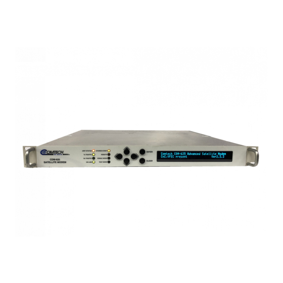
Page 27: Chapter 1. Introduction
Figure 1-1. CDM-625 Advanced Satellite Modem • The CDM-625 offers variable data rates from 18 to 25 Mbps, in BPSK, QPSK, Offset QPSK, 8-PSK, 8-QAM and 16-QAM modes. Viterbi, concatenated Reed-Solomon (RS), Trellis Coded Modulation (TCM), Turbo Product Coding (TPC), and Low-density Parity Check Coding (LDPC) are provided as Forward Error Correction (FEC) options. -
Page 28: Functional Description
CDM-625 Advanced Satellite Modem Revision 1 Introduction MN-0000036 (Ref MN/CDM625.IOM) Functional Description The CDM-625 has two fundamentally different types of interface - IF and data: • The IF interface provides a bidirectional link with the satellite via the uplink and downlink equipment. •... -
Page 29: Features
View Figure 1-3 shows the rear panel of the modem. External cables are attached to connectors on the rear panel of the CDM-625. Each connector is described in detail in Chapter 3. REAR PA NEL CONNECTOR PINOUTS. They comprise: 1–3... -
Page 30: Major Assemblies
CDM-625 Advanced Satellite Modem Revision 1 Introduction MN-0000036 (Ref MN/CDM625.IOM) Connector Group Name Connector Type Function (Chapter 3 Sect. Ref.) BNC female (70/140MHz band) IF Input (Sect. 3.2) Type ’N’ female (L-Band) BNC female (70/140MHz band) IF Output Type ’N’ female (L-Band) -
Page 31: Verification
1.3.4 Data Interfaces The CDM-625 includes, as standard, a universal data interface that eliminates the need to exchange interface cards for different applications. The interfaces offered include: • RS-422 (EIA530) DCE (at rates up to 14 Mbps) •... -
Page 32: Fast Accessible Options
115/230 volt AC Main Power Supply HARDWARE -48 volt DC HARDWARE 1.4.1 FAST Accessible Options Comtech EF Data’s FAST system allows immediate implementation of different options through the user interface keypad. All FAST options are available through the basic platform unit. 1–6... -
Page 33: Fast System Theory
The access code can be purchased at any time from Comtech EF Data. Once obtained, the access code is loaded into the unit through the front panel keyboard or the rear remote port. -
Page 34: Compatibility
BUC using the front panel display and keypad of the modem or the modem’s remote control interface. The EDMAC channel can be used to convey M&C interface to a BUC at the distant end of a satellite link if it is connected to a CDM-625. Compatibility The CDM-625 is fully backwards-compatible with the Comtech EF Data CDM-500, CDM-550, and CDM-550T modems (not including sequential FEC). -
Page 35: Summary Of Specifications
CDM-625 Advanced Satellite Modem Revision 1 Introduction MN-0000036 (Ref MN/CDM625.IOM) Summary of Specifications 1.7.1 Modulator BPSK, QPSK, OQPSK, 8-PSK, 8-QAM and 16-QAM Modulation 18 ksps to 12.5 Msps Symbol rate range 18 kbps - 25 Mbps. See Section 17.7 Data rate range... - Page 36 CDM-625 Advanced Satellite Modem Revision 1 Introduction MN-0000036 (Ref MN/CDM625.IOM) None: Uncoded BPSK/QPSK/OQPSK Viterbi: k=7, per IESS-308/309 BPSK: Rate 1/2 QPSK/OQPSK: Rate 1/2, Rate 3/4 and Rate 7/8 16-QAM: Rate 3/4 and Rate 7/8 (Viterbi plus Reed-Solomon only) Reed-Solomon (Open Network):...
- Page 37 CDM-625 Advanced Satellite Modem Revision 1 Introduction MN-0000036 (Ref MN/CDM625.IOM) Internal, ±0.06 ppm (SCT) Clocking options External, locking over a ±100 ppm range (TT) Loop timing (Rx satellite clock) - supports asymmetric operation - Rx and Tx data rates need not be identical External Clock G.703 Clock Extension mode –...
-
Page 38: Demodulator
CDM-625 Advanced Satellite Modem Revision 1 Introduction MN-0000036 (Ref MN/CDM625.IOM) 1.7.2 Demodulator Data rate range, operating modes, de-scrambling, input impedance/return loss etc, as per Modulator. Input power range, 950-1950 MHz band: -130 + 10 log(symbol rate) to -80 + 10 log(symbol rate) dBm... - Page 39 CDM-625 Advanced Satellite Modem Revision 1 Introduction MN-0000036 (Ref MN/CDM625.IOM) 8-PSK/TCM CODEC Rate 2/3 8-PSK/TCM Rate 2/3 8-PSK/TCM Guaranteed Eb/No: w/concatenated RS (typical value in Guaranteed Eb/No: (With two adjacent For: parentheses) (typical value in carriers, each 7 dB parentheses)
- Page 40 CDM-625 Advanced Satellite Modem Revision 1 Introduction MN-0000036 (Ref MN/CDM625.IOM) LDPC CODEC BER 8-PSK Rate 2/3 LDPC 8-PSK Rate 3/4 LDPC Guaranteed Eb/No: Guaranteed Eb/No: Rate 2/3 8-PSK (typical value in (typical value in Rate 3/4 8-PSK For: parentheses) parentheses)
-
Page 41: Data Interfaces
CDM-625 Advanced Satellite Modem Revision 1 Introduction MN-0000036 (Ref MN/CDM625.IOM) 1.7.3 Data Interfaces RS-422/EIA-530 DCE (Rates up to 14 Mbps) 25-pin D-sub (female) Primary Data (also supports X.21 DCE & DTE and 8k ESC orderwire for IDR) (4 selectable modes) V.35 DCE (Rates up to 14 Mbps) -
Page 42: Doubletalk ® Carrier-In-Carrier
CDM-625 Advanced Satellite Modem Revision 1 Introduction MN-0000036 (Ref MN/CDM625.IOM) ® ® 1.7.5 DoubleTalk Carrier-in-Carrier Requires the two links to share a common carrier frequency Operating Mode (Outbound and Inbound symbol rates do not have to be equal) From –7 dB to +11 dB (ratio of power spectral density, outbound interferer to desired inbound) -
Page 43: Framing Summary
CDM-625 Advanced Satellite Modem Revision 1 Introduction MN-0000036 (Ref MN/CDM625.IOM) 1.7.6 Framing Summary Scrambling Overhead added Available data Overhead Additional Reed- (see Note 1) rates and format components Solomon Overhead Transparent None All rates and None 200/220 Basic ITU formats 225/205 V.35 (Intelsat) -
Page 44: Data Rate Ranges
CDM-625 Advanced Satellite Modem Revision 1 Introduction MN-0000036 (Ref MN/CDM625.IOM) 1.7.7 Data Rate Ranges UNFRAMED, NO REED SOLOMON Lower Limit (kbps) Upper Limit (kbps) No FEC, BPSK 18.0 12500 No FEC, O/QPSK 36.0 25000.0 VITERBI, BPSK, 1/2 18.0 6250.0 VITERBI, O/QPSK, 1/2 18.0... - Page 45 CDM-625 Advanced Satellite Modem Revision 1 Introduction MN-0000036 (Ref MN/CDM625.IOM) TPC, O/QPSK, 3/4 26.6 18442.6 TPC, O/QPSK, 17/18 (aka 0.95) 33.5 23224.0 TPC, O/QPSK, 7/8 31.0 21516.3 TPC, 8-PSK/8-QAM, 3/4 39.9 25000.0 TPC, 8-PSK/8-QAM, 17/18 (aka 0.95) 50.2 25000.0 TPC, 8-PSK/8-QAM, 7/8 46.5...
- Page 46 CDM-625 Advanced Satellite Modem Revision 1 Introduction MN-0000036 (Ref MN/CDM625.IOM) LDPC, 8-PSK/8-QAM, 2/3 64.0 8448.0 LDPC, 16-QAM, 3/4 64.0 8448.0 IBS, ANY REED SOLOMON Lower Limit (kbps) Upper Limit (kbps) VITERBI, BPSK, 1/2 64.0 5208.0 VITERBI, O/QPSK, 1/2 64.0 8448.0 VITERBI, O/QPSK, 3/4 64.0...
-
Page 47: Miscellaneous
CDM-625 Advanced Satellite Modem Revision 1 Introduction MN-0000036 (Ref MN/CDM625.IOM) 1.7.8 Miscellaneous Tactile keypad, 6 keys (Up/Down), Left/Right, Enter/Clear) Front Panel Vacuum Fluorescent Display (blue) – 2 lines of 40 characters Internal IF loopback, RF loopback, digital loopback, and inward/outward loopback... - Page 48 CDM-625 Advanced Satellite Modem Revision 1 Introduction MN-0000036 (Ref MN/CDM625.IOM) Notes: 1–22...
-
Page 49: Chapter 2. Installation
Inspect shipping containers for damage. If shipping containers are damaged, keep them until the contents of the shipment have been carefully inspected and checked for normal operation. The CDM-625 Advanced Satellite Modem and its Installation and Operation Manual are packaged and shipped in a pre-formed, reusable cardboard carton containing foam spacing for maximum shipping protection. -
Page 50: Mounting
MN-0000036 (Ref MN/CDM625.IOM) Mounting If the CDM-625 is to be mounted in a rack, ensure that there is adequate clearance for ventilation, particularly at the sides. In rack systems where there is high heat dissipation, forced air cooling must be provided by top or bottom mounted fans or blowers. Under no circumstance should the highest internal rack temperature be allowed to exceed 50°C (122°F). -
Page 51: Configuration
CDM-625 Advanced Satellite Modem Revision 1 Installation MN-0000036 (Ref MN/CDM625.IOM) Equipment Rack Rear Mounting Rail #10 Shoulder Screw Support Bracket #10 Flat Washer #10 Flat Washer #10 Split Washer #10 Bracket Bolt #10 Hex Nut Back of unit Figure 2-1. Optional Rear-Mounting Support Bracket Installation... -
Page 52: Select Internal If Loop
From the top level menu, select TEST: IF LOOP (refer to Chapter 5. FRONT PANEL OPERATION). The demod should synchronize, and the green RECEIVE TRAFFIC LED should illuminate. If the unit does not pass this test, call Comtech EF Data's Customer Support department for assistance. -
Page 53: Chapter 3. Rear Panel Connector Pinouts
Table 3-1 on the next page summarizes the connectors provided on the rear panel interface, grouped according to service function. CDM-625 with AC Power Option CDM-625 with DC Power Option Figure 3-1. CDM-625 – Rear Panel View 3–1... -
Page 54: Table 3-1. Cdm-625 Rear Panel Connectors
CDM-625 Advanced Satellite Modem Revision 1 Rear Panel Connector Pinouts MN-0000036 (Ref MN/CDM625.IOM) Table 3-1. CDM-625 Rear Panel Connectors Connector Name Connector Type Function Group BNC female (70/140MHz band) IF Input Sect. 3.2 Type ’N’ female (L-band) BNC female (70/140MHz band) IF Output Type ’N’... -
Page 55: If Connections
CDM-625 Advanced Satellite Modem Revision 1 Rear Panel Connector Pinouts MN-0000036 (Ref MN/CDM625.IOM) IF Connections There may be DC voltages present on the Type ‘N’ Rx and Tx IF connectors, up to a maximum of 48 volts. CA UTIO N 3.2.1... -
Page 56: Terrestrial Data Connections
CDM-625 Advanced Satellite Modem Revision 1 Rear Panel Connector Pinouts MN-0000036 (Ref MN/CDM625.IOM) Terrestrial Data Connections 3.3.1 Data Interface Connector, DB-25F The Data Interface connector is a 25-pin, Type ‘D’ female interface that conducts data input and output signals to and from the modem, and connects to customer’s terrestrial equipment, breakout panel, or... -
Page 57: Hssi Operation Via The Data Interface Connector
For HSSI operation (Tx, Rx, or both), the optional CIC-60 Adapter Module, shown in Figure 3-2, may be purchased from Comtech EF Data to adapt the Data Interface 25-pin Type ‘D’ female connection to a standard 50-pin Type ‘HD’ HSSI (SCSI-II) female connection. Refer to Table 3-3 for the pin assignments for the HSSI side of the CIC-60 Adapter Module. -
Page 58: Table 3-3. Cic-60 Connector Pin Assignments (Hssi Side)
CDM-625 Advanced Satellite Modem Revision 1 Rear Panel Connector Pinouts MN-0000036 (Ref MN/CDM625.IOM) Table 3-3. CIC-60 Connector Pin Assignments (HSSI side) HSSI/EIA-613 Interface Connector Pinout HSSI EIA-613 Circuit Signal Function Pin # (+,-) Comment Signal Circuit Direction Signal Ground 1, 26... -
Page 59: Connectors
CDM-625 Advanced Satellite Modem Revision 1 Rear Panel Connector Pinouts MN-0000036 (Ref MN/CDM625.IOM) 3.3.2 G.703 Connectors 3.3.2.1 Balanced G.703 Connector, DB-9F The Balanced G.703 connector is a 9-pin Type ‘D’ female connector. It is used for single port G.703, D&I or D&I++; when used with Quad E1 operations, this connector serves Ports 1 and 2 of the Quad E1 interface. -
Page 60: Quad E1 Operation Via The Balanced G.703 / Aux G.703 Connectors
For Quad E1 operation, the optional CA-0000163 and CA-0000164 Adapter Cables, shown in Figure 3-3 and Figure 3-4 respectively, may be purchased from Comtech EF Data to adapt the Balanced G.703 or Auxiliary G.703 9-pin Type ‘D’ female connectors to either a standard 15-pin Type ‘D’ or a RJ-48 female connection pair. -
Page 61: Ca-0000164 Adapter Cable
CDM-625 Advanced Satellite Modem Revision 1 Rear Panel Connector Pinouts MN-0000036 (Ref MN/CDM625.IOM) 3.3.2.3.2 CA-0000164 Adapter Cable Figure 3-4. CA-0000164 Adapter Cable (DB-9M (2X) RJ-48F) Table 3-7. CA-0000164 Pin Assignments Twisted Signal Function Pair Port 1 or 3 Tx In +... -
Page 62: Quad Ethernet Connectors, Rj-45
CDM-625 Advanced Satellite Modem Revision 1 Rear Panel Connector Pinouts MN-0000036 (Ref MN/CDM625.IOM) 3.3.3 Quad Ethernet Connectors, RJ-45 These are four standard RJ-45 female connectors, operating at 10/100 Mbps, half and full duplex, auto-negotiating. 3.3.4 IDR Data / Alarms / Audio Connector, HD-44F Table 3-8. -
Page 63: Esc Connector, Db-9F
CDM-625 Advanced Satellite Modem Revision 1 Rear Panel Connector Pinouts MN-0000036 (Ref MN/CDM625.IOM) 3.3.5 ESC Connector, DB-9F The ESC (Engineering Service Channel) port is a 9-pin Type ‘D’ female connector. Refer to Table 3-9 for pin assignments. Table 3-9. ESC Connector Pin Assignments... -
Page 64: Alarms Connector, Db-15M
CDM-625 Advanced Satellite Modem Revision 1 Rear Panel Connector Pinouts MN-0000036 (Ref MN/CDM625.IOM) 3.4.2 Alarms Connector, DB-15M Unit alarms are provided on a 15-pin Type ‘D’ male connector. Refer to Table 3-11 for pin assignments. Table 3-11. Alarm Interface Connector Pin Assignments... -
Page 65: 1:1 Control Connector, Db-9F
CDM-625 Advanced Satellite Modem Revision 1 Rear Panel Connector Pinouts MN-0000036 (Ref MN/CDM625.IOM) 3.4.4 1:1 Control Connector, DB-9F The 1:1 Control connector is a 9-pin Type ‘D’ female connector. Refer to Table 3-13 for pin assignments. Note: The 1:1 Control connector is intended only for connection to a CRS-170A or CRS-180 Redundancy Switch. -
Page 66: Power / Ground Connections
CDM-625 Advanced Satellite Modem Revision 1 Rear Panel Connector Pinouts MN-0000036 (Ref MN/CDM625.IOM) Power / Ground Connections 3.5.1 Alternating Current Power Connector A standard, detachable, non-locking, 3-prong power cord (IEC plug) supplies the Alternating Current (AC) power to the modem via this connector. -
Page 67: Chassis Ground Connector
CDM-625 Advanced Satellite Modem Revision 1 Rear Panel Connector Pinouts MN-0000036 (Ref MN/CDM625.IOM) 3.5.3 Chassis Ground Connector A #10-32 stud adjacent to the power connector is used for connecting a common chassis ground among equipment. Note: The AC power connector provides the safety ground. - Page 68 CDM-625 Advanced Satellite Modem Revision 1 Rear Panel Connector Pinouts MN-0000036 (Ref MN/CDM625.IOM) Notes: 3–16...
-
Page 69: Chapter 4. Flash Upgrading
• New firmware can be downloaded via the Internet to an external PC. • The upgrade can be performed without opening the CDM-625 by simply connecting the unit to the serial port of a computer. • The firmware update is transferred, via File Transfer Protocol (FTP), to the CDM-625. -
Page 70: Ethernet Ftp Upload Procedure
– see Step 1); revision letter, if applicable; version; and release date. The base modem bulk firmware for the CDM-625 is FW12864*_*_* (where the asterisks signify revision, version and release date). The current version firmware release is provided. If applicable, one version prior to the current release is also available. - Page 71 Releasenotes.pdf c. README.TXT installation notes 5. Connect the external PC to any one of the four CDM-625 modem 10/100 Ethernet ports, via a hub or a switch, or directly to a PC with a crossover cable. 6. Send a “ping” command to the modem to verify the communication and connection.
- Page 72 Verify the new software versions are booting by observing the following messages on the modem display: Comtech CDM-625 Advanced Satellite Modem Ver 1.1.5 Note: If the Top Card Application has been changed, when booting into a new image an additional step will occur as the modem downloads to a different flash memory.
-
Page 73: Chapter 5. Front Panel Operation
Indicators Figure 5-1. CDM-625 – Front Panel View The user can fully control and monitor the operation of the CDM-625 from the front panel using the keypad and display. Nested menus are used, which display all available options, and prompt the user to carry out a required action. -
Page 74: Front Panel Led Indicators
CDM-625 Advanced Satellite Modem Revision 1 Front Panel Operation MN-0000036 (Ref MN/CDM625.IOM) 5.1.1 Front Panel LED Indicators In general, the Alarm relay state will reflect the state of the Front Panel LEDs. For instance, if the Unit Status LED is red, the Unit Alarm relay will be active, etc. The one exception is the Transmit Traffic relay. -
Page 75: Front Panel Keypad
Down) 5.1.3 Front Panel Vacuum Fluorescent Display (VFD) The CDM-625 features a Vacuum Fluorescent Display (VFD). The VFD is an active display showing two lines of 40 characters each. It produces a blue light, the brightness of which can be controlled by the user. -
Page 76: Opening Screen
The CDM-625 modem is designed to be a ‘drop-in’ replacement for the CDM-600 and CDM-600L modems. To be able to do this, the CDM-625 has an emulation mode, which may be configured via remote control (using the remote command mnemonic EMU), or via the front panel, Utility: Em. -
Page 77: Figure 5-2. Cdm-625 Front Panel Principle Menu Tree
VIEW FOR SELECTED PORT AUPC PARAMETERS REMOTE Eb/No, TX PWR INCREASE CnC PARAMETERS RX PARAMETERS CnC PARAMS: FREQ-OFFSET = +011.7kHz RX PARAMETERS: Eb/No=12.6dB dF=+011.7kHz RATIO +10dB DELAY = 245.8ms BER=1.2E-4 BUFFER=54% RX-LEVEL=-55dBm Figure 5-2. CDM-625 Front Panel Principle Menu Tree 5–5... -
Page 78: Select: (Main) Menu
CDM-625 Advanced Satellite Modem Revision 1 Front Panel Operation MN-0000036 (Ref MN/CDM625.IOM) SELECT: (Main) Menu Select: Configuration Test Monitor Info Store/Ld Utility FAST (34) ◄ ► Use the arrow keys to select from the choices shown, then press ENTER. The following... -
Page 79: Select: Configuration
CDM-625 Advanced Satellite Modem Revision 1 Front Panel Operation MN-0000036 (Ref MN/CDM625.IOM) SELECT: Configuration CONFIG: Mode Clocks D&I EDMAC Misc Mask Remote (34) ◄ ► Use the arrow keys to select from the submenu choices shown, then press ENTER. The... -
Page 80: Config: All
CDM-625 Advanced Satellite Modem Revision 1 Front Panel Operation MN-0000036 (Ref MN/CDM625.IOM) 5.4.1 CONFIG: All All = Stop (Stop, Start) This menu permits the user to configure the unit, in a step-by-step process, by viewing each menu in ◄ ►... - Page 81 EDMAC2 (as in the CDM-570) • ESC++ EDMAC is Comtech EF Data’s proprietary framing. The framing permits bi-directional passing of M&C and AUPC (Automatic Uplink Power Control) data between local and distant-end units. EDMAC is backwards compatible with the CDM-500, CDM-550, CDM-550T, CDM-600 and CDM-600L.
-
Page 82: Config: Tx
CDM-625 Advanced Satellite Modem Revision 1 Front Panel Operation MN-0000036 (Ref MN/CDM625.IOM) 5.4.3 CONFIG: Tx Tx-IF Freq Power FEC Mod Data Scrambler (Data 00192.000kbps, 00131.657ksym) (34) Select the parameter on the top line using the ◄ ► arrow keys – the submenu branches available are Tx-IF, Freq, Power, FEC, Mod, Data, and Scrambler –... -
Page 83: Config: Tx Freq (Frequency)
CDM-625 Advanced Satellite Modem Revision 1 Front Panel Operation MN-0000036 (Ref MN/CDM625.IOM) 5.4.3.2 CONFIG: Tx Freq (Frequency) Tx-IF Frequency: 0050.0000 MHz (34v) Select each digit of the frequency to be edited using the ◄ ► arrow keys. Edit the value of the digit using the arrow keys, then press ENTER when done. -
Page 84: Config: Tx Fec
CDM-625 Advanced Satellite Modem Revision 1 Front Panel Operation MN-0000036 (Ref MN/CDM625.IOM) Selecting Target-EbNo-Range displays the following menu: Minimum EbNo of Remote Modem = 5.0dB Max Permitted Power Increase = 9dB (34v) Edit the Target Eb/No of the remote modem. The default value is 3.0 dB; the upper limit is 14.9 dB. -
Page 85: Config: Tx
CDM-625 Advanced Satellite Modem Revision 1 Front Panel Operation MN-0000036 (Ref MN/CDM625.IOM) If the user selects Differential Encoding=OFF, there is no way for the modem to resolve the phase ambiguities associated with PSK modulations. For BPSK there is a 1 in 2 chance that the polarity of the data will be correct. In QPSK IMPORTANT there is a 1 in 4 chance the data will be correct. - Page 86 CDM-625 Advanced Satellite Modem Revision 1 Front Panel Operation MN-0000036 (Ref MN/CDM625.IOM) BPSK 5/16, 21/44 QPSK, OQPSK 1/2 (aka 21/44), 3/4, 7/8, 0.95 TPC (with TPC/LDPC 8-PSK (FAST option) 3/4, 7/8, 0.95 Codec installed) 16-QAM (FAST option) 3/4, 7/8 BPSK...
- Page 87 CDM-625 Advanced Satellite Modem Revision 1 Front Panel Operation MN-0000036 (Ref MN/CDM625.IOM) 5.4.3.7 CONFIG: Tx Scrambler Tx Scrambler = Normal (Normal,Off) Frame Scrambler Select either On or Off using the arrow keys, then press ENTER. ▲ ▼ The choice of scrambler is selected automatically, and depends on the exact operating mode: •...
-
Page 88: Config: Rx
CDM-625 Advanced Satellite Modem Revision 1 Front Panel Operation MN-0000036 (Ref MN/CDM625.IOM) 5.4.4 CONFIG: Rx RxIF Freq FEC Demod Data Descram Eq EbNo (Data 02048.000kbps,02184.533ksym) (34v) Select the parameter on the top line using the ◄ ► arrow keys – the submenu branches available are RxIF, Freq, FEC, Demod, Data, Descrambler, Eq, and EbNo –... -
Page 89: Config: Rx Freq (Frequency)
CDM-625 Advanced Satellite Modem Revision 1 Front Panel Operation MN-0000036 (Ref MN/CDM625.IOM) 5.4.4.2 Config: Rx Freq (Frequency) Rx-IF Frequency: 0050.0000 MHz (34v) Select each digit of the frequency to be edited using the ◄ ► arrow keys. Edit the value of the digit using the arrow keys. -
Page 90: Config: Rx Fec Reed-Solomon On
CDM-625 Advanced Satellite Modem Revision 1 Front Panel Operation MN-0000036 (Ref MN/CDM625.IOM) If None is selected, the bottom line of the display changes from the Reed-Solomon selection to a Differential Encoding selection, as shown: Decoder=None (None,Vit,TCM,TPC,LDPC) Diff-Decoder=On (Off,On) (34v) If the user selects Differential Decoding = OFF, there is no way for the modem to resolve the phase ambiguities associated with PSK modulations. -
Page 91: Config: Rx Data Rate
CDM-625 Advanced Satellite Modem Revision 1 Front Panel Operation MN-0000036 (Ref MN/CDM625.IOM) The Decoder type dictates the FEC Rate choices: Decoder Type Modulation Type FEC Rate Choice BPSK Fixed at 1/1 No Encoder QPSK, OQPSK Fixed at 1/1 BPSK Fixed at Rate 1/2... -
Page 92: Config: Rx Descram (Descrambler)
CDM-625 Advanced Satellite Modem Revision 1 Front Panel Operation MN-0000036 (Ref MN/CDM625.IOM) In QDI (Quad D&I) mode, these data rates are read-only! The data rate will be the sum of the tributary rates for all ports, and must be edited via the QDI menu. -
Page 93: Config: Rx Ebno
CDM-625 Advanced Satellite Modem Revision 1 Front Panel Operation MN-0000036 (Ref MN/CDM625.IOM) may be viewed on the monitor screen. The equalizer is then turned on, and the Eb/No viewed on the monitor screen to determine any improvement. 5.4.4.8 CONFIG: Rx EbNo Receive EbNo Alarm Point = 02.0 dB... -
Page 94: Config: Clocks
CDM-625 Advanced Satellite Modem Revision 1 Front Panel Operation MN-0000036 (Ref MN/CDM625.IOM) 5.4.5 CONFIG: Clocks Clocking: TxClock RxBuffer/Clock Clock-Ext Freq-Ref Int-Ref-Adjust (34) Select one of the parameters using the ◄ ► arrow keys – the submenus branches available are TxClock, RxBuffer/Clock, Clock-Ext, Freq-Ref, and Int-Ref-Adjust – then press ENTER. -
Page 95: Config: Clocks Rx Buffer/Clock
CDM-625 Advanced Satellite Modem Revision 1 Front Panel Operation MN-0000036 (Ref MN/CDM625.IOM) 5.4.5.2 CONFIG: Clocks Rx Buffer/Clock Clk=Rx-Sat (Rx-Sat,TxTerr,Int(SCT),Ins) Buffer-Size = 00016bytes(00002ms) Center se the arrow keys to select from the choices shown in parentheses. Then, to edit the Rx ▲... -
Page 96: Config: Clocks Rx Buffer/Clock Center
If the user selects Interface, the following sub menu is displayed: G.703 Clock Extension: Interface: T1 (T1, E1-B, E1-U) If TxLock is selected as the mode, the transmit timing of the CDM-625 will be locked to the timing presented to interface type selected here. 5–24... - Page 97 Front Panel Operation MN-0000036 (Ref MN/CDM625.IOM) If RxEnable is selected as the mode the CDM-625 will generate a timing signal of the type selected here. Note: For a particular link, the two interface types need not be the same. For example: If it is required to generate an E1 reference signal at the remote site, but at the local end only a T1 reference signal is available, this is supported.
-
Page 98: Config: D&I (Drop & Insert)
CDM-625 Advanced Satellite Modem Revision 1 Front Panel Operation MN-0000036 (Ref MN/CDM625.IOM) 5.4.6 CONFIG: D&I (Drop & Insert) For a detailed discussion of Drop & Insert, refer to Chapter 9. CLOCK MODES and DROP & INSERT (D&I). IMPORTANT If D&I has not been selected, the menu displays as shown:... -
Page 99: Config: D&I Insert Channel Timeslots
CDM-625 Advanced Satellite Modem Revision 1 Front Panel Operation MN-0000036 (Ref MN/CDM625.IOM) 5.4.6.2 CONFIG: D&I Insert Channel Timeslots Ins-Ch: TS: 01 ◄ ► Select the Channel to edit using the arrow keys, edit the timeslot value using the ▲ ▼... -
Page 100: Config: Quad Drop & Insert (Qdi)
CDM-625 Advanced Satellite Modem Revision 1 Front Panel Operation MN-0000036 (Ref MN/CDM625.IOM) 5.4.7 CONFIG: Quad Drop & Insert (QDI) Quad D&I (QDI): Drop Insert (34) ◄ ► Select Drop or Insert using the arrow keys, then press ENTER. 5.4.7.1 CONFIG: Quad D&I... - Page 101 CDM-625 Advanced Satellite Modem Revision 1 Front Panel Operation MN-0000036 (Ref MN/CDM625.IOM) QDI Ins-Ch: > Port#X TS: 01 02 03 04 11 12 13 14 The display can only show up to 8 channels. If a character is displayed at the top right-hand >...
-
Page 102: Config: Cnc
CDM-625 Advanced Satellite Modem Revision 1 Front Panel Operation MN-0000036 (Ref MN/CDM625.IOM) 5.4.8 CONFIG: CnC Carrier in Carrier: Mode Freq-Offset Search-Delay PMSI (34) See Chapter 10. DoubleTalk ® ® OPTION for more information about this Carrier-in-Carrier feature. Select Mode, Freq-Offset, Search-Delay, or PMSI using the ◄... -
Page 103: Config: Cnc Frequency Offset
Data part number CA-0000102) needs to be connected to the PMSI connector on the rear panel of each modem. Consult Comtech EF Data Customer Service for details about this cable. arrow keys to select the desired configuration, then press ENTER. -
Page 104: Config: Edmac
CDM-625 Advanced Satellite Modem Revision 1 Front Panel Operation MN-0000036 (Ref MN/CDM625.IOM) 5.4.9 CONFIG: EDMAC EDMAC Mode= Idle (Idle,Master,Slave) (34v) EDMAC is a Comtech-proprietary framing which permits communication access to the distant- end modem. For further information, refer to Chapter 11. EDMAC CHANNEL. In order to edit the EDMAC mode, the framing must be set for EDMAC, EDMAC-2 or D&I++. -
Page 105: Config: Misc
CDM-625 Advanced Satellite Modem Revision 1 Front Panel Operation MN-0000036 (Ref MN/CDM625.IOM) 5.4.10 CONFIG: Misc Misc: G.703-LineCode IDR-ESC HSSI Audio-Vol HiRateESC WarmUp Stats (34) ◄ ► Select the parameter using the arrow keys, then press ENTER. 5.4.10.1 CONFIG: Misc G.703 Ternary Code Tx G.703/DDO Code= AMI... -
Page 106: Config: Misc Hssi Handshake Control
CDM-625 Advanced Satellite Modem Revision 1 Front Panel Operation MN-0000036 (Ref MN/CDM625.IOM) 5.4.10.3 CONFIG: Misc HSSI Handshake Control HSSI handshake control: (2 options) TA-> CA loop Note: This control setting is only applicable is the data interface type is HSSI. -
Page 107: Config: Misc High-Rate-Esc
CDM-625 Advanced Satellite Modem Revision 1 Front Panel Operation MN-0000036 (Ref MN/CDM625.IOM) 5.4.10.6 CONFIG: Misc High-Rate-ESC High-Rate-ESC=Off (Off,On) RS-232 2400 baud DataParityStop=8N1 (34v) The ESC (Engineering Service Channel) is determined by the framing type selected under CONFIG: Mode. The two options are either High-Rate IBS ESC, or ESC++. -
Page 108: Config: Misc Warm-Up
CDM-625 Advanced Satellite Modem Revision 1 Front Panel Operation MN-0000036 (Ref MN/CDM625.IOM) 5.4.10.7 CONFIG: Misc Warm-Up High-Stab Reference Warm-Up Delay: Enabled (None,Enable) The High-Stability Reference Module contains an oven for the crystal. It can take a little time for the oven & crystal to come up to temperature; during this time, the frequency accuracy is not guaranteed. -
Page 109: Config: Mask
CDM-625 Advanced Satellite Modem Revision 1 Front Panel Operation MN-0000036 (Ref MN/CDM625.IOM) 5.4.11 CONFIG: Mask The Mask submenus permit the user to selectively mask, or make active, various alarms and traffic conditions that are monitored in the modem. Alarm Masks: AIS Buffer Ref RxIF TxClk TxSat RxSat Terr-Alarm BUC LNB CEX (34) Use the ◄... -
Page 110: Config: Mask Txclk
CDM-625 Advanced Satellite Modem Revision 1 Front Panel Operation MN-0000036 (Ref MN/CDM625.IOM) 5.4.11.3 CONFIG: Mask Rx-IF RxIF Alarms: AGC=Active (Active,Mask) EbNo=Masked (34v) ◄ ► Use the arrow keys to select the parameter to edit: AGC or EbNo. Select Active or Masked using the arrow keys, then press ENTER. - Page 111 CDM-625 Advanced Satellite Modem Revision 1 Front Panel Operation MN-0000036 (Ref MN/CDM625.IOM) 5.4.11.7 CONFIG: Mask Terr-Alarm Terr-Alm: Tx= Active (Active,Mask) Rx= Off (Off,Enabled)(34v) Note: These alarms are applicable for D&I operation only. ◄ ► Use the arrow keys to select the parameter to edit. Edit the alarm mask using the ▲...
-
Page 112: Config: Mask Lnb
CDM-625 Advanced Satellite Modem Revision 1 Front Panel Operation MN-0000036 (Ref MN/CDM625.IOM) 5.4.11.9 CONFIG: Mask LNB alarm = Active (Active,Mask) Attach to Rx alarm = No (Yes,No)(34v) When using L-band, a LNB (Low-Noise Block) may be included in the system. It cannot be monitored and/or controlled by the modem, except for the power supply values. -
Page 113: Config: Remote Control
CDM-625 Advanced Satellite Modem Revision 1 Front Panel Operation MN-0000036 (Ref MN/CDM625.IOM) 5.4.12 CONFIG: Remote Control Remote Control=Local (Local,Remote,Ethernet) Select Local, Remote or Ethernet using the arrow keys, then press ENTER. ▲ ▼ If Local is selected, then reconfiguration via Remote or Ethernet is not permitted. Remote monitoring is still possible. -
Page 114: Config: Ip
CDM-625 Advanced Satellite Modem Revision 1 Front Panel Operation MN-0000036 (Ref MN/CDM625.IOM) 5.4.13 CONFIG: IP IP Config: Addresses SNMP Switch-set-up (34) Use the ◄ ► arrow keys to select the parameter to configure. 5.4.13.1 CONFIG: IP Addresses IP Addresses: Gateway... -
Page 115: Config: Ip Snmp
CDM-625 Advanced Satellite Modem Revision 1 Front Panel Operation MN-0000036 (Ref MN/CDM625.IOM) 5.4.13.2 CONFIG: IP SNMP SNMP: Communities Traps (34) ◄ ► Use the arrow keys to select the parameter to configure: Communities or Traps. CONFIG: IP SNMP Communities SNMP Communities:... -
Page 116: Config: Ip Snmp Traps Community
CDM-625 Advanced Satellite Modem Revision 1 Front Panel Operation MN-0000036 (Ref MN/CDM625.IOM) CONFIG: IP SNMP Traps Community SNMP Traps Community: Comtech (20 chars) (34v) This menu permits the user to edit the SNMP Traps Community string. Only the first 20 characters on the bottom line are available. -
Page 117: Config: Ip (Ethernet) Switch Set-Up Stats
CDM-625 Advanced Satellite Modem Revision 1 Front Panel Operation MN-0000036 (Ref MN/CDM625.IOM) CONFIG: IP (Ethernet) Switch set-up Stats IP stats: Port x (34v) Unicasts: 00000003 00000023 Clr:N This menu show the IP traffic statistics for both the In (Ingress) and Out (Egress) directions. -
Page 118: Select: Test
CDM-625 Advanced Satellite Modem Revision 1 Front Panel Operation MN-0000036 (Ref MN/CDM625.IOM) SELECT: Test Modem Test Mode = Normal (NORM,Tx-CW,Tx-1/0,IF↓,RF↓,DIG↓,I/O↓) Select a Test Mode or Normal Operation from the parameters shown in the parentheses using arrow keys, then press ENTER. -
Page 119: Figure 5-3. Loopback Modes
CDM-625 Advanced Satellite Modem Revision 1 Front Panel Operation MN-0000036 (Ref MN/CDM625.IOM) Figure 5-3. Loopback Modes 5–47... -
Page 120: Select: Monitor
CDM-625 Advanced Satellite Modem Revision 1 Front Panel Operation MN-0000036 (Ref MN/CDM625.IOM) SELECT: Monitor Monitor: Live-Alarms Stored-Events Statistics Rx-Params AUPC IP (34) ◄ ► Select the parameter to monitor using the arrow keys, then press ENTER 5.6.1 Monitor: Live-Alarms Live... - Page 121 CDM-625 Advanced Satellite Modem Revision 1 Front Panel Operation MN-0000036 (Ref MN/CDM625.IOM) Demod Lock: indicates either the demodulator or the following FEC decoder cannot Receive lock to the incoming signal. AGC Alarm: is indicated if the demod signal level is out of range.
-
Page 122: Monitor: Stored Events
CDM-625 Advanced Satellite Modem Revision 1 Front Panel Operation MN-0000036 (Ref MN/CDM625.IOM) 5.6.2 Monitor: Stored Events Stored Events: Clear-All: No (No,Yes) #199 FT- Frame Sync 25/10/07 16:25:24 An example of a Stored Events screen is shown. ◄ ► Use the arrow keys to select the ‘#’... -
Page 123: Monitor: Statistics
CDM-625 Advanced Satellite Modem Revision 1 Front Panel Operation MN-0000036 (Ref MN/CDM625.IOM) 5.6.3 Monitor: Statistics Statistics: Sta114: 16.0,16.0,9.0,9.0 09/12/99 14:48:06 Clear-All: No (N/Y) The user may scroll backwards or forwards through the entries in the statistics log using the ▲ ▼... -
Page 124: Monitor: Rx Parameters
CDM-625 Advanced Satellite Modem Revision 1 Front Panel Operation MN-0000036 (Ref MN/CDM625.IOM) 5.6.4 Monitor: Rx Parameters ΔF=+011.7kHz Rx-Parameters: EbNo=11.4dB BER=0.0E-9 Buffer=51% RxLevel=-43.5dBm If the demodulator is locked, this screen shows the following: This shows the value of Eb/No calculated by the demodulator. The value... -
Page 125: Select: Info (Information)
CDM-625 Advanced Satellite Modem Revision 1 Front Panel Operation MN-0000036 (Ref MN/CDM625.IOM) SELECT: Info (Information) Info: All ID Mode Clocks EDMAC Drop Insert Remote Alarm-Mask Misc Select the information menu to view using the ◄ ► arrow keys, then press ENTER. -
Page 126: Info: Tx
CDM-625 Advanced Satellite Modem Revision 1 Front Panel Operation MN-0000036 (Ref MN/CDM625.IOM) 5.7.4 Info: Tx Tx:On 0070.0000MHz PWR=-20.0 TSI=N Vit+RS:220/200 00064.000 QPSK Scrm A sample display of Tx Info is shown. The information displayed here is as follows: Top Line:... -
Page 127: Info: Edmac
CDM-625 Advanced Satellite Modem Revision 1 Front Panel Operation MN-0000036 (Ref MN/CDM625.IOM) 5.7.7 Info: EDMAC EDMAC Function= On EDMAC Mode= Master EDMAC Addr= 0020 This screen shows if EDMAC is enabled or not. If it is enabled, the EDMAC Mode and Address are shown. -
Page 128: Info: Alarms Mask
CDM-625 Advanced Satellite Modem Revision 1 Front Panel Operation MN-0000036 (Ref MN/CDM625.IOM) 5.7.11 Info: Alarms Mask Alarms Masked: TxAIS Terr REF TxClk Buf-Slip RxAIS EbNo This modem screen shows only the alarm(s) that are currently masked, though all are shown for this example. -
Page 129: Select: Store/Ld (Store/Load)
CDM-625 Advanced Satellite Modem Revision 1 Front Panel Operation MN-0000036 (Ref MN/CDM625.IOM) SELECT: Store/Ld (Store/Load) Configuration #2: Load Store (34v) AVAILABLE Move the cursor to the configuration location number using the ◄ ► arrow keys. Edit the value using the arrow keys. -
Page 130: Select: Utility
CDM-625 Advanced Satellite Modem Revision 1 Front Panel Operation MN-0000036 (Ref MN/CDM625.IOM) SELECT: Utility Utilities: Set-RTC Display-Brightness Circuit-ID Firmware Select a Utilities parameter using the ◄ ► arrow keys, then press ENTER 5.9.1 Utilities: Set-RTC Edit Real-Time Clock: Time: 12:01:02... -
Page 131: Utilities: 1:N
TECHNICIAN. IMPORTANT This series of submenus permits the user to view information about the CDM-625 internal firmware. The modem can store two complete firmware images, and the user can select which image will be loaded the next time the unit reboots. -
Page 132: Utilities: Firmware Select
The CDM-625 modem is designed to be a ‘drop-in’ replacement for the CDM-600 and CDM- 600L modems. To be able to do this, the CDM-625 has an emulation mode, which may be configured via remote control, using the remote command mnemonic EMU or, via the front panel, Utility:Em. -
Page 133: Select: Odu
CDM-625 Advanced Satellite Modem Revision 1 Front Panel Operation MN-0000036 (Ref MN/CDM625.IOM) 5.10 SELECT: ODU The CDM-625 modem is able to interface with various ODUs (Outdoor Units). These are: • Comtech RF Transceivers: CSAT-5060, KST-2000 series • L-band BUC (Block Up Converter) •... -
Page 134: Odu: Buc:pwrsupply+Ref Lo Frequency
CDM-625 Advanced Satellite Modem Revision 1 Front Panel Operation MN-0000036 (Ref MN/CDM625.IOM) 5.10.1.2 ODU: BUC:PwrSupply+Ref LO Frequency BUC-LO Frequency= 00000 MHz Mix= High [-] (Hi,Lo) (34v) This menu permits the user to enter the BUC LO frequency for the up conversion. Entering a non- zero value for BUC LO will cause the Tx-IF frequency menu to show LO and Satellite frequencies. - Page 135 CDM-625 Advanced Satellite Modem Revision 1 Front Panel Operation MN-0000036 (Ref MN/CDM625.IOM) 5.10.2.2 ODU: LNB:PwrSupply+Ref LO Frequency LNB-LO Frequency= 00000 MHz Mix= High [-] (Hi,Lo) (34v) This menu permits the user to enter the LNB LO frequency for the up conversion. Entering a non- zero value for LNB LO will cause the Rx-IF frequency menu to show LO and Satellite frequencies.
-
Page 136: Odu: Fsk-Control
CDM-625 Advanced Satellite Modem Revision 1 Front Panel Operation MN-0000036 (Ref MN/CDM625.IOM) ◄ ► Use the arrow keys to move the cursor to the ODU type, and edit it from the selection available using the arrow keys. Then press ENTER. The modem will then attempt to ▲... -
Page 137: Odu: Fsk-Control 2 Csats
CDM-625 Advanced Satellite Modem Revision 1 Front Panel Operation MN-0000036 (Ref MN/CDM625.IOM) The menu indicates: • which of the two CSATs in currently online • Operating mode • Waveguide Switch status, both Tx and Rx: Ok or Ft (fault) •... -
Page 138: Odu: Fsk-Control (2 Csats) Csat Configuration Rx
CDM-625 Advanced Satellite Modem Revision 1 Front Panel Operation MN-0000036 (Ref MN/CDM625.IOM) ◄ ► Use the arrow keys to select the parameter to edit. Use the arrow keys to edit the ▲ ▼ parameter, then press ENTER to implement, or CLEAR to cancel and return to the previous menu. -
Page 139: Odu: Fsk-Control (2 Csats) Csat Monitor
CDM-625 Advanced Satellite Modem Revision 1 Front Panel Operation MN-0000036 (Ref MN/CDM625.IOM) If enabled, when the CSAT is powered on, the IF and RF outputs will remain Cold-Start muted for 15 minutes. (Auto Fault Recovery) This defines how a CSAT will react to momentary fault conditions: Off: CSAT will mute when faulted and remain muted. -
Page 140: Odu: Fsk-Control (2 Csats) Csat Monitor Power-Supplies
CDM-625 Advanced Satellite Modem Revision 1 Front Panel Operation MN-0000036 (Ref MN/CDM625.IOM) ODU: FSK-control (2 CSATs) CSAT Monitor Power-Supplies 24V=24.1 VDC 12V=12.5VDC +5V=+5.4VDC 20V=21.2 VDC 10V=10.2VDC -5V=-5.3VDC Press ENTER or CLEAR to return to previous menu. 5.10.7.3 ODU: FSK-control (2 CSATs) -
Page 141: Odu: Fsk-Control (2 Csats) Csat Information
CDM-625 Advanced Satellite Modem Revision 1 Front Panel Operation MN-0000036 (Ref MN/CDM625.IOM) To clear the Stored Alarms Log, select YES using the arrow keys in the Clear-All option, ▲ ▼ then press ENTER. 5.10.7.4 ODU: FSK-control (2 CSATs) CSAT Information... -
Page 142: Odu: Fsk-Control (2 Csats) Csat Information Lna
CDM-625 Advanced Satellite Modem Revision 1 Front Panel Operation MN-0000036 (Ref MN/CDM625.IOM) ODU: FSK-control (2 CSATs) CSAT Information Info: LNA:Off Fault-Logic:Summary Window:48% (EC) Press ENTER or CLEAR to return to previous menu. 5.10.8 ODU: FSK-control KST Select: Conguration Information Alarms (34) ◄... -
Page 143: Odu: Fsk-Control
CDM-625 Advanced Satellite Modem Revision 1 Front Panel Operation MN-0000036 (Ref MN/CDM625.IOM) ODU: FSK-control Configuration Miscellaneous HPA:Off Fault-Logic=Summary LNA:OFF Fault-Logic=Summary Cal:No ◄ ► Use the arrow keys to select the parameter to edit, then use the arrow keys to edit the ▲... -
Page 144: Odu: Fsk-Control
CDM-625 Advanced Satellite Modem Revision 1 Front Panel Operation MN-0000036 (Ref MN/CDM625.IOM) Note: The Rx Band information is not shown for the KST-2000A. Press ENTER or CLEAR to return to previous menu. ODU: FSK-control Information Numbers M&C: F/W:9364-1B VER:01.01.03 assy:9357-1A... -
Page 145: Select: Fast
Demo-Mode Motherboard S/N 123456789 HW Rev 1.0 FAST (Fully Accessible System Topology) is the way to enable new options in the modem. Obtain the FAST code for the new option from Comtech EF Data. The options include: • Data Rate •... - Page 146 CDM-625 Advanced Satellite Modem Revision 1 Front Panel Operation MN-0000036 (Ref MN/CDM625.IOM) Register 2 contains the lockdown for: • Open Network • Modulation: o 8PSK/8QAM, o 16QAM • Drop & Insert: o 1-port (D&I) o 4-port (Quad D&I) • L-band •...
- Page 147 ▲ ▼ seconds remaining for the free Demo Mode. When enabled, Demo Mode allows access to ALL CDM-625 FAST options for 604800 seconds (7 full days). Demo Mode may be turned on and off an unlimited number of time until the 604800 seconds have expired.
- Page 148 CDM-625 Advanced Satellite Modem Revision 1 Front Panel Operation MN-0000036 (Ref MN/CDM625.IOM) Notes: 5–76...
-
Page 149: Chapter 6. Ethernet Management
The CDM-625 SNMP agent supports both SNMPv1 and v2c. For proper SNMP operation, the CDM-625 MIB files must be used with the associated version of the CDM-625 modem M&C. Please refer to the CDM-625 FW Release Notes for information on the required FW/SW compatibility. -
Page 150: Snmp Community Strings
There are three MIB files associated with the CDM-625 : MIB File/Name Description FW10874-2-.mib ComtechEFData MIB file gives the root tree for ALL Comtech EF Data products and consists of only the following OID: ComtechEFData MIB file Name: comtechEFData Type: MODULE-IDENTITY OID: 1.3.6.1.4.1.6247... -
Page 151: Snmp Traps
CDM-625 Advanced Satellite Modem Revision 1 Ethernet Management MN-0000036 (Ref MN/CDM625.IOM) 6.3.3 SNMP Traps The modem has the ability to send out SNMP traps when certain events occur in the modem. The modem sends out traps when an alarm or a fault occurs in the modem. These include unit faults, TX faults, RX faults, and ODU faults. -
Page 152: Telnet Interface
CDM-625 Advanced Satellite Modem Revision 1 Ethernet Management MN-0000036 (Ref MN/CDM625.IOM) Telnet Interface The modem provides a Telnet interface for the purpose of Equipment M&C via the standard equipment Remote Control protocol. The Telnet interface Requires user login at the Administrator level and Read/Write level. -
Page 153: Web Server (Http) Interface
The embedded Web Server application provides the user with an easy to use interface to configure and monitor all aspects of the CDM-625. These Web pages have been designed for optimal performance when using Microsoft’s Internet Explorer Version 5.5 or higher (the examples shown use Internet Explorer Version 6.0). -
Page 154: User Login
Type the User Name and Password, then click [OK]. Once the valid User Name and Password is accepted, the user will see the CDM-625 Advanced Satellite Modem Web Server Interface “splash” page (right). From this top level menu, the user has access to five (5) navigation tabs: •... -
Page 155: Web Server Page Descriptions
6.5.4.1 Home Page 6.5.4.1.1 Home | Home Page Figure 6-1. CDM-625 Satellite Modem Home page From any location within the Web Server Interface, the user can select the Home tab and/or hyperlink to return back to this top-level page. 6–7... -
Page 156: Home | Contact Page
MN-0000036 (Ref MN/CDM625.IOM) 6.5.4.1.2 Home | Contact Page Figure 6-2. Home | Contact Information page The ‘Contact’ page (Figure 6-2) provides basic contact informatio n to reach Comtech EF Data Sales and Customer Support via phone or automated e-mail links. 6–8... -
Page 157: Home | Support Page
Home | Support Page Figure 6-3. Home | Customer Support page The CDM-625 ‘Support’ page (Figure 6-3) allows the user to compose an e-mail message for questions or problems with the modem. The Problem Report area of the display allows up to 256 characters maximum. -
Page 158: Admin
Figure 6-4. Admin | Access page The ‘Admin | Access’ page (Figure 6-4) provides the means to set up user names, passwords, the e-mail server, and the host IP addresses to facilitate communication with the CDM-625 Web Server. System Account Access Information •... - Page 159 CDM-625 Advanced Satellite Modem Revision 1 Ethernet Management MN-0000036 (Ref MN/CDM625.IOM) • SMTP Server: Specify the mail server IP address from where you want to send the e- mail. • SMTP Domain Name / Destination: The Administrator can assign the SMTP Domain Name and Destination.
-
Page 160: Figure 6-5. Admin | Snmp Page
Figure 6-5. Admin | SNMP page The ‘Admin | SNMP’ page (Figure 6-5) sets and returns administration information for the CDM-625 Simple Network Management Protocol (SNMP) feature. The Administrator can assign up to two SNMP Trap IP addresses. The Administrator can assign a SNMP Trap Community String. The factory default for this parameter is public. -
Page 161: Figure 6-6. Config | Ip Page
CDM-625 Advanced Satellite Modem Revision 1 Ethernet Management MN-0000036 (Ref MN/CDM625.IOM) 6.5.4.3 Config (Configuration) Pages The ‘Config Mdm’ pages (Figure 6-6 through Figure 6-12) are used to configure all modem parameters. 6.5.4.3.1 Config | IP Figure 6-6. Config | IP page The ‘Config | IP’... -
Page 162: Figure 6-7. Config | Modem Page
CDM-625 Advanced Satellite Modem Revision 1 Ethernet Management MN-0000036 (Ref MN/CDM625.IOM) 6.5.4.3.2 Config | Modem Figure 6-7. Config | Modem page The ‘Config | Modem’ page (Figure 6-7) is used to configure modem operating (Tx / Rx) param eters including: •... - Page 163 CDM-625 Advanced Satellite Modem Revision 1 Ethernet Management MN-0000036 (Ref MN/CDM625.IOM) 6.5.4.3.3 Config | Overhead Figure 6-8. Config | Overhead page The ‘Config | Overhead’ page (Figure 6-8) is used to configure the following overhead interfaces: • ESC, including Tx / Rx IDR Esc Type, Audio Volume, High Rate ESC •...
- Page 164 6.5.4.3.4 Config | Utilities Figure 6-9. Config | Utilities page The ‘Config | Utilities’ page (Figure 6-9) is used to configure the following CDM-625 utility functions: Unit o Test Mode, Sats Sample Interval, Front Panel Lockout, RTS/CTS Control, and HSSI Handshake Control.
-
Page 165: Date And Time
CDM-625 Advanced Satellite Modem Revision 1 Ethernet Management MN-0000036 (Ref MN/CDM625.IOM) Date and Time o The user may enter a date using international format in the form DD/MM/YY (where DD = day [01 to 31], MM = month [01 to 12], and YY = year [00 to 99]). - Page 166 CDM-625 Advanced Satellite Modem Revision 1 Ethernet Management MN-0000036 (Ref MN/CDM625.IOM) 6.5.4.3.5 Config | D&I (Drop and Insert) Figure 6-10. Config | D&I page The appearance of the ‘Config | D&I’ page (Figure 6-10) is dependent on the framing mode selected on the ‘Config | Modem’...
-
Page 167: Config | Buc (Block Up Converter)
CDM-625 Advanced Satellite Modem Revision 1 Ethernet Management MN-0000036 (Ref MN/CDM625.IOM) 6.5.4.3.6 Config | BUC (Block Up Converter) Figure 6-11. Config | BUC page The ‘Config | BUC’ page (Figure 6-11) is used to configure Block Up Converter parameters, and display the BUC status for L-Band operation. -
Page 168: Config | Lnb (Low Noise Block Down Converter)
CDM-625 Advanced Satellite Modem Revision 1 Ethernet Management MN-0000036 (Ref MN/CDM625.IOM) 6.5.4.3.7 Config | LNB (Low Noise Block Down Converter) Figure 6-12. Config | LNB page The ‘Config | LNB’ page (Figure 6-12) is used to configure Low Noise Block Down Converter parameters, and display the LNB status for L-Band operation. -
Page 169: Status
CDM-625 Advanced Satellite Modem Revision 1 Ethernet Management MN-0000036 (Ref MN/CDM625.IOM) 6.5.4.4 Status Pages The Status pages provide the user with status, event logging, and operational statistics windows. 6.5.4.4.1 Status | Modem Status Page Figure 6-13. Status | Modem Status page The ‘Status | Modem Status’... -
Page 170: Status | Modem Logs Page
CDM-625 Advanced Satellite Modem Revision 1 Ethernet Management MN-0000036 (Ref MN/CDM625.IOM) 6.5.4.4.2 Status | Modem Logs Page Figure 6-14. Status | Modem Logs page The ‘Status | Modem Logs’ page (Figure 6-14) provides the user with control over how the following parameters are processed by the unit: •... -
Page 171: Status | Firmware Info Page
CDM-625 Advanced Satellite Modem Revision 1 Ethernet Management MN-0000036 (Ref MN/CDM625.IOM) 6.5.4.4.3 Status | Firmware Info Page Figure 6-15. Status | Firmware Info page The ‘Status | Firmware Info’ page (Figure 6-15) provides the user with read-only status windows that permit the user to view information about the currently loaded Bootrom; for Image 1 and Image 2, the user can scroll through information of all the constituent firmware blocks that make up the bulk. -
Page 172: Status | Ethernet Statistics Page
CDM-625 Advanced Satellite Modem Revision 1 Ethernet Management MN-0000036 (Ref MN/CDM625.IOM) 6.5.4.4.4 Status | Ethernet Statistics Page Figure 6-16. Status | Ethernet Statistics page The ‘Status | Ethernet Statistics’ page (Figure 6-16) is used to view Ethernet Statistics on a ‘Per Port’... -
Page 173: Odu (Outdoor Unit)
The ‘ODU (Outdoor Unit)’ pages are used to control and monitor the CSAT-5060 or KST-2000A/B Outdoor Unit that is connected via FSK to the CDM-625. ODU Comms must be enabled in order for the user to be able to fully access the ‘ODU | Config’, ‘ODU | Status’, and ‘ODU | Utilities’... -
Page 174: Odu | Config Page
CDM-625 Advanced Satellite Modem Revision 1 Ethernet Management MN-0000036 (Ref MN/CDM625.IOM) 6.5.4.5.2 ODU | Config Page Note: If the user attempts to access the ‘ODU | Config’ page without first enabling ODU communications as shown in the previous section, the following error page is displayed: Otherwise, when properly configured to operate with either the CSAT-5060 or the KST-2000A/B ODU, the ‘ODU | Config’... - Page 175 CDM-625 Advanced Satellite Modem Revision 1 Ethernet Management MN-0000036 (Ref MN/CDM625.IOM) Figure 6-18 shows the ‘ODU | Config’ page as it appears with the CSAT-5060 configured as the ODU. The user can use this page to configure the primary Transmit and Receive Parameters of a CSAT-5060 ODU.
-
Page 176: Odu | Config Page (Kst-2000A/B)
CDM-625 Advanced Satellite Modem Revision 1 Ethernet Management MN-0000036 (Ref MN/CDM625.IOM) 6.5.4.5.2.2 ODU | Config Page (KST-2000A/B) Figure 6-19. ODU | Config page (KST-2000A/B) Figure 6-19 shows the ‘ODU | Config’ page with the KST-2000A/B configured as the ODU. The user can use this page to configure the primary Transmit and Receive Parameters of a KST- 2000A/B ODU. -
Page 177: Odu | Status Page
Note: The appearance of the ‘ODU | Status’ page changes depending on which type of ODU had been configured for operation with the CDM-625. These pages provide the user with read-only status windows pertaining to the current operating condition for either the CSAT-5060 or the KST-2000A/B ODUs. -
Page 178: Odu | Status Page (Kst-2000A/B)
CDM-625 Advanced Satellite Modem Revision 1 Ethernet Management MN-0000036 (Ref MN/CDM625.IOM) ODU Selection If redundant ODUs are used, the CSAT-5060 ‘ODU | Status’ page can be toggled between the Online and Offline units by selecting CSAT #1 or CSAT #2, then clicking Select ODU. A message identifies the currently active unit as ‘ONLINE’... -
Page 179: Odu | Utilities Page
ODU | Utilities Page Note: The appearance of the ‘ODU | Utilities’ page changes depending on which type of ODU had been configured for operation with the CDM-625. This page is used to configure various ODU utility functions. 6.5.4.5.4.1 ODU | Utilities Page (CSAT-5060) Figure 6-22. - Page 180 CDM-625 Advanced Satellite Modem Revision 1 Ethernet Management MN-0000036 (Ref MN/CDM625.IOM) Re-Calibrate LNA Current Click to recalibrate the LNA Current. Redundancy Box Mode Select Automatic or Manual, then click [Submit] as needed to save those changes. ODU Date and Time •...
-
Page 181: Odu | Utilities Page (Kst-2000A/B)
CDM-625 Advanced Satellite Modem Revision 1 Ethernet Management MN-0000036 (Ref MN/CDM625.IOM) 6.5.4.5.4.2 ODU | Utilities Page (KST-2000A/B) Figure 6-23. ODU | Utilities page (KST-2000A/B) Figure 6-23 shows the ‘ODU | Utilities’ page, as it appears with the KST-2000A/B configured as the ODU. - Page 182 CDM-625 Advanced Satellite Modem Revision 1 Ethernet Management MN-0000036 (Ref MN/CDM625.IOM) Notes: 6–34...
-
Page 183: Introduction
(i.e., does not fail rapidly below a certain value of Eb/No). Note that, in BPSK mode, the CDM-625 only permits a coding rate of 1/2. Because the method of convolutional coding used with Viterbi, the encoder does not preserve the original data intact, and is called non-systematic. -
Page 184: Closed Network Modes
R-S decoder do not exceed its capacity to correct those errors. In the case of the CDM-625, different R-S code rates are used, according to the mode of operation: Closed Network Modes and Open Network Modes. -
Page 185: Open Network Modes
This may be due to the carrier-recovery circuits, or the synchronization threshold of the primary FEC device, or both. In the CDM-625, and Rate 1/2 operation, this threshold is around 4 dB Eb/No. Below this value, operation is not possible, but above this value, the error performance of the concatenated R-S system produces exceptionally low error rates for a very small increase in Eb/No. -
Page 186: Turbo Product Codec (Hardware Option)
– the natural consequences of the higher- order modulation. The CDM-625 fully implements the IESS-310 specification at data rates up to 20 Mbps. In accordance with the specification, the R-S outer code can be disabled. Performance curves for both cases are shown in the following Figures. -
Page 187: Tpc And Low Density Parity Check (Ldpc) Coding
CDM-625 Advanced Satellite Modem Revision 1 Forward Error Correction Options MN-0000036 (Ref MN/CDM625.IOM) TPC and Low Density Parity Check (LDPC) coding 7.6.1 Introduction In the past few years there has been an unprecedented resurgence in interest in Forward Error Correction (FEC) technology. The start of this new interest has its origins in the work done by Claude Berrou et al, and the landmark paper in 1993 - Near Shannon Limit Error Correcting Coding and Decoding - Turbo Codes. -
Page 188: Ldpc Versus Tpc
In order to take full advantage of the coding gain increase that LDPC provides, it became necessary to find an alternative to 8-PSK. Comtech EF Data has therefore developed an 8-QAM approach that permits acquisition and tracking at much lower values of Eb/No than 8-PSK. -
Page 189: Table 7-4. Available Tpc And Ldpc Modes
25000.0 Rate 3/4 16-QAM This new LDPC/TPC codec module may be installed in any existing CDM-625 as a simple field upgrade, or can be pre-installed in new modems ordered from the factory. It also requires the appropriate FAST codes for enabling operation beyond the base data rate limit of 5 Mbps. -
Page 190: End-To-End Processing Delay
Viterbi/Reed-Solomon * The occupied bandwidth is defined at the width of the transmitted spectrum taken at the –10 dB points on the plot of power spectral density. This equates to 1.19 x symbol rate for the CDM-625 transmit filtering. ** Included for comparative purposes 7.6.3 End-to-End Processing Delay... -
Page 191: Uncoded Operation (No Fec)
There are occasions where a user may wish to operate a satellite link with no forward error correction of any kind. For this reason, the CDM-625 offers this uncoded mode for three modulation types - BPSK, QPSK, and OQPSK. However, the user should be aware of some of the implications of using this approach. - Page 192 8 kHz. If there is any frequency uncertainty on the incoming carrier, this should be subtracted from the sweep width. The problem becomes progressively better with increasing symbol rate. Comtech EF Data cannot be held responsible for incorrect operation if the user does not adhere to these guidelines when using uncoded operation. 7–10...
- Page 193 CDM-625 Advanced Satellite Modem Revision 1 Forward Error Correction Options MN-0000036 (Ref MN/CDM625.IOM) Eb/No in dB 1E-1 Uncoded BPSK/QPSK Viterbi Decoding 1E-2 Typical Performance 1E-3 1E-4 1E-5 1E-6 Specification limit, Rate 7/8 1E-7 Coding 1E-8 Specification Specification limit Rate 1/2...
- Page 194 CDM-625 Advanced Satellite Modem Revision 1 Forward Error Correction Options MN-0000036 (Ref MN/CDM625.IOM) Eb/No in dB 1E-1 Viterbi with Uncoded BPSK/QPSK concatenated RS 220,200 1E-2 Outer Code Sync threshold, Rate 3/4 1E-3 Sync threshold, Rate 7/8 1E-4 Combined sync 1E-5...
- Page 195 CDM-625 Advanced Satellite Modem Revision 1 Forward Error Correction Options MN-0000036 (Ref MN/CDM625.IOM) Eb/No in dB 1E-1 8-PSK/TCM Rate 2/3 Uncoded BPSK/QPSK Decoding, with and without 219, 201 RS 1E-2 Outer Code 1E-3 1E-4 Typical Performance 1E-5 1E-6 1E-7 1E-8...
- Page 196 CDM-625 Advanced Satellite Modem Revision 1 Forward Error Correction Options MN-0000036 (Ref MN/CDM625.IOM) Eb/No in dB 1E-1 16-QAM Viterbi, Rate 3/4 and Rate 7/8 with 220,200 RS Outer Code Uncoded BPSK/QPSK 1E-2 Uncoded 16-QAM 1E-3 1E-4 Specification limit Rate 7/8...
- Page 197 CDM-625 Advanced Satellite Modem Revision 1 Forward Error Correction Options MN-0000036 (Ref MN/CDM625.IOM) Eb/No in dB 1E-1 Comtech Turbo Product Codec Rate 5/16 BPSK Uncoded BPSK/QPSK 1E-2 1E-3 Spec limit Rate 5/16 BPSK 1E-4 1E-5 1E-6 1E-7 1E-8 Typical performance 1E-9 Figure 7-5.
- Page 198 CDM-625 Advanced Satellite Modem Revision 1 Forward Error Correction Options MN-0000036 (Ref MN/CDM625.IOM) Eb/No in dB 1E-1 Comtech Turbo Product Codec Rate 21/44 BPSK/QPSK/OQPSK Uncoded BPSK/QPSK 1E-2 Notes: * Rate 21/44 QPSK is shown as R1/2 on the front panel...
- Page 199 CDM-625 Advanced Satellite Modem Revision 1 Forward Error Correction Options MN-0000036 (Ref MN/CDM625.IOM) Eb/No in dB 1E-1 Comtech Turbo Product Codec Rate 3/4 QPSK/OQPSK, Uncoded 8-PSK/8-QAM and 16-QAM BPSK/QPSK 1E-2 Uncoded 16-QAM Spec limit - Uncoded Spec limit Rate 3/4...
- Page 200 CDM-625 Advanced Satellite Modem Revision 1 Forward Error Correction Options MN-0000036 (Ref MN/CDM625.IOM) Eb/No in dB 1E-1 Comtech Turbo Product Codec Rate 7/8 QPSK/OQPSK, Uncoded 8-PSK/8-QAM and 16-QAM BPSK/QPSK 1E-2 Uncoded Uncoded 16-QAM Spec limit - 8-PSK Rate 7/8 QPSK/OQPSK...
- Page 201 CDM-625 Advanced Satellite Modem Revision 1 Forward Error Correction Options MN-0000036 (Ref MN/CDM625.IOM) Eb/No in dB 1E-1 Comtech Turbo Product Codec Rate 0.95 QPSK/OQPSK Uncoded BPSK/QPSK and 8-PSK/8-QAM 1E-2 Spec limit Rate 0.95 QPSK/OQPSK 1E-3 Uncoded 8-PSK 1E-4 1E-5 1E-6...
- Page 202 CDM-625 Advanced Satellite Modem Revision 1 Forward Error Correction Options MN-0000036 (Ref MN/CDM625.IOM) Eb/No in dB 1E-1 Comtech LDPC Codec Rate 1/2 BPSK/QPSK/OQPSK Uncoded BPSK/QPSK 1E-2 Note: The OQPSK demod 1E-3 acquisition and tracking threshold is about 1 dB worse than the QPSK...
- Page 203 CDM-625 Advanced Satellite Modem Revision 1 Forward Error Correction Options MN-0000036 (Ref MN/CDM625.IOM) Eb/No in dB 1E-1 Comtech LDPC Rate 2/3 QPSK/OQPSK Uncoded BPSK/QPSK and 8-PSK/8-QAM 1E-2 1E-3 Spec limit Spec limit Rate 2/3 Rate 2/3 Uncoded QPSK/OQPSK 8-QAM 8-PSK...
- Page 204 CDM-625 Advanced Satellite Modem Revision 1 Forward Error Correction Options MN-0000036 (Ref MN/CDM625.IOM) Eb/No in dB 1E-1 Comtech LDPC Rate 3/4 QPSK/OQPSK Uncoded BPSK/QPSK 8-PSK/8-QAM and 16-QAM 1E-2 1E-3 Spec limit Spec limit Rate 3/4 Rate 3/4 8-PSK Uncoded QPSK/OQPSK...
- Page 205 CDM-625 Advanced Satellite Modem Revision 1 Forward Error Correction Options MN-0000036 (Ref MN/CDM625.IOM) Eb/No in dB 1E-1 Differential Encoding - No FEC, no Uncoded BPSK/QPSK 1E-2 scrambling 1E-3 1E-4 1E-5 1E-6 1E-7 1E-8 1E-9 Figure 7-13. Differential Encoding - No FEC, No Scrambling...
- Page 206 CDM-625 Advanced Satellite Modem Revision 1 Forward Error Correction Options MN-0000036 (Ref MN/CDM625.IOM) Notes: 7–24...
-
Page 207: Chapter 8. Automatic Uplink Power Control
Chapter 8. AUTOMATIC UPLINK POWER CONTROL Introduction Automatic Uplink Power Control (AUPC) is a feature whereby a local modem is permitted to adjust its own output power level in order to attempt to maintain the Eb/No at the remote modem. The user MUST obtain permission from the Satellite Operator to use this feature. -
Page 208: Setting Aupc Parameters
CDM-625 Advanced Satellite Modem Revision 1 Automatic Uplink Power Control (AUPC) MN-0000036 (Ref MN/CDM625.IOM) Setting AUPC Parameters 1) The user, under the menu SELECT: Configuration Mode, first ensures that EDMAC is selected. EDMAC may be selected as IDLE, or the unit may be defined as an EDMAC Master or Slave. -
Page 209: Alarm
CDM-625 Advanced Satellite Modem Revision 1 Automatic Uplink Power Control (AUPC) MN-0000036 (Ref MN/CDM625.IOM) 8.2.3 Alarm This parameter defines how the user wants the modem to act if, under AUPC control, the maximum power limit is reached. The two choices are: •... -
Page 210: Monitoring
AUPC is disabled, this will indicate 0.0 dB. This value is also available via the remote control interface. Comtech EF Data strongly cautions against the use of large values of permitted power level increase under AUPC control. Users should consider using the absolute minimum range necessary to improve rain-fade margin. -
Page 211: Introduction
DTE also returns the clock (Terminal Timing, or TT) - the modem can accept it if it is present, but uses ST if it is not. At rates above 2 Mbps, Comtech EF Data highly recommends that the user returns TT to ensure the correct clock/data relationship. -
Page 212: Tx Terrestrial
9.2.2 in that, in this mode, the signal appearing on TT is used to provide the timing reference for the transmit side of the CDM-625. However, in this mode, the ST pins on the interface are active and provide a copy of the Rx Satellite clock (i.e., the clock from the demodulator, prior to the buffer). -
Page 213: Receive Clocking
Clock Modes and Drop and Insert (D&I) MN-0000036 (Ref MN/CDM625.IOM) Receive Clocking There are three receive clocking modes in the CDM-625, plus an additional setting used for Drop and Insert only – see later section. 9.3.1 Buffer Disabled (RX Satellite) When the buffer is disabled, the receive clock (Receive Timing, or RT) is derived directly from the demodulator, and hence will be subject to plesiochronous and Doppler offsets. - Page 214 CDM-625 Advanced Satellite Modem Revision 1 Clock Modes and Drop and Insert (D&I) MN-0000036 (Ref MN/CDM625.IOM) Figure 9-1. Tx Clock Modes 9–4...
- Page 215 CDM-625 Advanced Satellite Modem Revision 1 Clock Modes and Drop and Insert (D&I) MN-0000036 (Ref MN/CDM625.IOM) Figure 9-2. Rx Clock Modes 9–5...
-
Page 216: Drop And Insert
CDM-625 Advanced Satellite Modem Revision 1 Clock Modes and Drop and Insert (D&I) MN-0000036 (Ref MN/CDM625.IOM) Drop and Insert The Drop and Insert (D&I) multiplexer works in conjunction with the G.703 interfaces to enable the modem to transmit or receive fractional parts of a T1 or E1 data stream. -
Page 217: Time Slot Selection
CDM-625 Advanced Satellite Modem Revision 1 Clock Modes and Drop and Insert (D&I) MN-0000036 (Ref MN/CDM625.IOM) Time Slot Selection Selection of the transmit and receive data rates may be made in certain 64 kbps increments and may be independent of each other. The actual satellite rates for open network D&I are 16/15 of... -
Page 218: Drop And Insert (D&I) Clocking
MN-0000036 (Ref MN/CDM625.IOM) Drop and Insert (D&I) Clocking The general arrangement for Drop and Insert clocking in the CDM-625 is shown below: Figure 9-4. Drop and Insert Clocking Note that there are two inputs and two outputs shown for Drop and Insert Operation:... -
Page 219: Single-Source Multiple Modems
CDM-625 Advanced Satellite Modem Revision 1 Clock Modes and Drop and Insert (D&I) MN-0000036 (Ref MN/CDM625.IOM) detects no activity at IDI input, or cannot detect the expected frame format, Buffer Clock = Rx Satellite will be chosen as a fall-back. -
Page 220: Clock Extension
G.703 synchronizing signal. However, with the G.703 clock extension mode, this may become uneccessary, as the CDM-625 – operating at either end of the link, where the local modem has access to a high-stability G.703 signal – can provide an almost perfect copy of this signal at the distant end. -
Page 221: Clock Extension Mode 2
CDM-625 Advanced Satellite Modem Revision 1 Clock Modes and Drop and Insert (D&I) MN-0000036 (Ref MN/CDM625.IOM) The net result is that the E1 or T1 timing signal used at the local end is reproduced at the distant end, regardless of the link data rate. - Page 222 CDM-625 Advanced Satellite Modem Revision 1 Clock Modes and Drop and Insert (D&I) MN-0000036 (Ref MN/CDM625.IOM) LOCAL END DISTANT END USER USER EQUIPMENT EQUIPMENT Demod Demod Buffer Notes: Clock Synth Core 1) The EIA-530 / v.35 interface can operate at any data rate, with...
- Page 223 CDM-625 Advanced Satellite Modem Revision 1 Clock Modes and Drop and Insert (D&I) MN-0000036 (Ref MN/CDM625.IOM) LOCAL END DISTANT END USER USER EQUIPMENT EQUIPMENT Demod * TT assumed to be Notes: *ST optional derived from a high stability source 1) The modems can be set to any...
- Page 224 CDM-625 Advanced Satellite Modem Revision 1 Clock Modes and Drop and Insert (D&I) MN-0000036 (Ref MN/CDM625.IOM) LOCAL END DISTANT END Rx clock at desired link data rate Demod DATA ETHERNET ETHERNET (HDLC) (HDLC) DATA Demod Notes: Any desired 1) The IP interface can be set to...
-
Page 225: Chapter 10. Doubletalk
The transponder downlinks the composite signal containing both carriers on the same band to the CDM-625 which then translates the signal to near baseband where it can be filtered (decimated) and then processed as a complex envelope signal. The CDM-625 then suppresses the version of the near end carrier on the downlink side and then passes the desired carrier to the demodulator for normal processing. - Page 226 Option MN-0000036 (Ref MN/CDM625.IOM) Upconverter Downconverter Upconverter Downconverter CDM-600 Satellite Modem CDM-600 Satellite Modem Figure 10-1. Conventional FDMA Link CDM-625 with CnC CDM-625 with CnC CDM-625 with CnC ® ® Figure 10-2. Same Link Using CDM-625 and DoubleTalk Carrier-in-Carrier 10–2...
-
Page 227: Application Requirements
• Link must be full duplex. • A CDM-625 must be used at the end of the link where the cancellation needs to take place. • The transponder is operated as Loopback. That is, each end of the link must be able to see a copy of its own signal in the return (downlink) path from the satellite. - Page 228 2) Frequency offset and drift. Common sources are satellite Doppler shift, up and down converter frequency uncertainties, and other drift associated with the electronics in the CDM-625 itself. The CnC module tracks and compensates for this frequency offset and drift.
-
Page 229: Symbol Rate And Doubletalk Carrier-In-Carrier Ratio
10.4 Symbol Rate and DoubleTalk Carrier-in-Carrier Ratio In the CDM-625 implementation of CnC, there is no restriction on the ratio of symbol rates for the outbound interferer and the desired inbound carrier. There could, therefore, be a significant difference in symbol rates. - Page 230 3 dB CnC ratio when the CnC carriers have the same spectral density. During CnC operation, the interfering carrier is removed by the CDM-625 using a stored version of the transmitted carrier to adaptively cancel it from the composite received signal. The desired carrier remaining after the cancellation process is delivered to the demodulator and decoder to recover the data.
-
Page 231: Cnc Carrier Frequency Offset
CDM-625 Advanced Satellite Modem Revision 1 ® ® DoubleTalk Carrier-in-Carrier Option MN-0000036 (Ref MN/CDM625.IOM) 10.5 CnC Carrier Frequency Offset CnC carriers are normally placed directly on top of each other with the same center frequency for both carriers. Normal operation is obtained when the center frequency of the two carriers is within the normal acquisition range of the modem for standard and CnC carriers. - Page 232 CDM-625 Advanced Satellite Modem Revision 1 ® ® DoubleTalk Carrier-in-Carrier Option MN-0000036 (Ref MN/CDM625.IOM) Site A Site B Parameter Comment Parameter Comment Relative Level of Due to fade @ A Relative Level of Due to fade @ A Carrier A @ Site A...
-
Page 233: Nd Cnc Example: Cnc Ratio With Asymmetric Links
CDM-625 Advanced Satellite Modem Revision 1 ® ® DoubleTalk Carrier-in-Carrier Option MN-0000036 (Ref MN/CDM625.IOM) 10.7 2 CnC Example: CnC Ratio With Asymmetric Links Networks with asymmetric antennas are common with a larger antenna at one site (hub) and smaller ones at the other sites (remotes) and often have asymmetric data rates. In a number of links even a significant rain fade is not a big factor in CnC performance. - Page 234 CDM-625 Advanced Satellite Modem Revision 1 ® ® DoubleTalk Carrier-in-Carrier Option MN-0000036 (Ref MN/CDM625.IOM) Parameters Site A Site B Satellite EIRP (dBW) Satellite BOo (dB) Satellite BOi (dB) Satellite SFD (dbW/m Satellite G/T (dB/K) E/S Antenna (meters) Data Rate (kbps)
-
Page 235: Rd Cnc Example: Asymmetric Link With Rain Fade
CDM-625 Advanced Satellite Modem Revision 1 ® ® DoubleTalk Carrier-in-Carrier Option MN-0000036 (Ref MN/CDM625.IOM) 10.8 3 CnC Example: Asymmetric Link With Rain Fade A reasonable question to ask about the previous example is the impact rain fade has on the link. -
Page 236: Summary Of Specifications
CDM-625 Advanced Satellite Modem Revision 1 ® ® DoubleTalk Carrier-in-Carrier Option MN-0000036 (Ref MN/CDM625.IOM) 10.9 Summary of Specifications Operating Mode Requires the two links to share a common carrier frequency (Outbound and Inbound symbol rates do not have to be equal) Power Spectral Density From –7 dB to +11 dB (ratio of power spectral density, outbound interferer to desired... -
Page 237: Chapter 11. Edmac Channel
Chapter 11. EDMAC CHANNEL 11.1 Theory Of Operation As explained earlier, EDMAC is an acronym for Embedded Distant-end Monitor And Control. This is a feature that permits the user to access the M&C features of modems that are at the distant-end of a satellite link. -
Page 238: M&C Connection
CDM-625 Advanced Satellite Modem Revision 1 EDMAC Channel MN-0000036 (Ref MN/CDM625.IOM) by a factor of 10log(1.05), or 0.21 dB (0.07dB in the case of the two BPSK Turbo rates or EDMAC-2). The use of an externally synchronized scrambler and descrambler almost exactly compensates for this degradation. -
Page 239: Setup Summary
CDM-625 Advanced Satellite Modem Revision 1 EDMAC Channel MN-0000036 (Ref MN/CDM625.IOM) of 19,200 baud. It should be pointed out that at 2.4 kbps, the effective throughput of the overhead channel is only 11 async characters/second. For a message of 24 bytes, the time between sending a poll request and receiving a response will be around 5 seconds. - Page 240 CDM-625 Advanced Satellite Modem Revision 1 EDMAC Channel MN-0000036 (Ref MN/CDM625.IOM) Notes: 11–4...
-
Page 241: Chapter 12. Esc
25 Mbps may be used with ESC++. In all cases, if the Reed-Solomon outer codec is used, the 126/112 ratio is employed with ESC++. The new frame structure may be used with any FEC codec type available with the CDM-625. 12–1... -
Page 242: Available Baud Rates
CDM-625 Advanced Satellite Modem Revision 1 ESC++ MN-0000036 (Ref MN/CDM625.IOM) 12.3 Available Baud Rates At the lowest data rates, the 11.76% overhead may not allow all baud rates. The following table shows available rates: Data rate Baud rates available 64 to 127.999 kbps 1200, 2400, 4800 128 to 191.999 kbps... -
Page 243: Chapter 13. Offset Qpsk Operation
Chapter 13. OFFSET QPSK OPERATION Offset QPSK modulation is a variation of normal QPSK, which is offered in the CDM-625. Normal bandlimited QPSK produces an RF signal envelope that necessarily goes through a point of zero amplitude when the modulator transitions through non-adjacent phase states. This is not considered to be a problem in most communication systems, as long as the entire signal processing chain is linear. - Page 244 CDM-625 Advanced Satellite Modem Revision 1 Offset QPSK Operation MN-0000036 (Ref MN/CDM625.IOM) Notes: 13–2...
-
Page 245: Overview
Chapter 14. OPEN NETWORK OPERATIONS 14.1 Overview This chapter summarizes the functionality and specifications of the various Open Network operating modes: • • Drop and Insert (D&I) • 14.2 IBS Primary Data Rates Supported G.703 1544, 2048, 6312 and 8448 kbps SD, RD EIA-422, V.35, LVDS N x 64 kbps SD, RD (up to 8448 kbps) ADPCM Audio... -
Page 246: Ibs Clock/Data Recovery And De-Jitter
CDM-625 Advanced Satellite Modem Revision 1 Open Network Operations MN-0000036 (Ref MN/CDM625.IOM) 14.2.1 IBS Clock/data Recovery and De-jitter Performs clock and data recovery on the G.703 format. Clock de-jitter and data encoding/decoding is done as with the IDR configuration. 14.2.2... -
Page 247: Drop And Insert (D&I)
CDM-625 Advanced Satellite Modem Revision 1 Open Network Operations MN-0000036 (Ref MN/CDM625.IOM) 14.3 Drop and Insert (D&I) Primary Data Rates Supported 1544 kbps SD, RD, DDO, IDI G.703, EIA-422, V.35 and Serial LVDS 2048 kbps SD, RD, DDO, IDI N x 64 kbps... -
Page 248: D&I Primary Data Interfaces
CDM-625 Advanced Satellite Modem Revision 1 Open Network Operations MN-0000036 (Ref MN/CDM625.IOM) 14.3.1 D&I Primary Data Interfaces When configured for D&I operation, multiplexing/demultiplexing follows the IBS satellite frame structure and ESC features, but with the following changes: • Accepts and outputs primary data through the G.703 connectors. -
Page 249: Idr
CDM-625 Advanced Satellite Modem Revision 1 Open Network Operations MN-0000036 (Ref MN/CDM625.IOM) 14.4 IDR Primary Data Rates Supported G.703 1544 kbps SD, RD EIA-422 (Replaces 8K Overhead) 2048 kbps SD, RD V.35 (Replaces 8K Overhead) 6312 kbps SD, RD 8448 kbps SD, RD... -
Page 250: Idr Primary Data Interfaces
CDM-625 Advanced Satellite Modem Revision 1 Open Network Operations MN-0000036 (Ref MN/CDM625.IOM) 14.4.1 IDR Primary Data Interfaces When configured for IDR operation, the board performs these functions: • Receives and performs clock and data recovery on incoming G.703 T1 and E1 pseudo-ternary data. -
Page 251: Appendix A. Cable Drawings
Figure A-1 depicts the cable required for EIA-530 to EIA-422/449 DCE conversion • Figure A-2 depicts the cable required for EIA-530 to V.35 DCE conversion • Figure A-3 depicts a standard EIA-232 cable for use with the Remote Control port of the CDM-625. -
Page 252: To Rs-422/449 Data Cable
MN-0000036 (REF MN/CDM625.IOM) A.1.1 EIA-530 to RS-422/449 Data Cable Figure A-1 depicts the cable drawing for a EIA-530 to RS-422/449 DCE conversion for connections between the CDM-625 and the user data. Figure A-1. DCE Conversion Cable – EIA-530 to RS-422/449 (CA/WR0049) -
Page 253: To V.35 Data Cable
MN-0000036 (REF MN/CDM625.IOM) A.1.2 EIA-530 to V.35 Data Cable Figure A-2 depicts the cable drawing for a EIA-530 to V.35 DCE conversion for connections between the CDM-625 and the user data. Figure A-2. DCE Conversion Cable – EIA-530 to V.35... -
Page 254: Remote Control Cable
MN-0000036 (REF MN/CDM625.IOM) A.1.3 RS-232 Remote Control Cable Figure A-3 depicts the cable required for a simple RS-232 connection between the CDM-625 Remote Control port and a PC serial port. This cable is needed for Flash upgrading. Figure A-3. CDM-625 RS-232 Remote Control Port to PC 9-Pin Serial Port... -
Page 255: Appendix B. Eb/No Measurement
Appendix B. Eb/No MEASUREMENT Although the CDM-625 calculates and displays the value of receive E on the front panel of the unit, it is sometimes useful to measure the value using a spectrum analyzer, if one is available. The idea is to accurately measure the value of (Co+No)/No, (Carrier density + Noise density/Noise density). - Page 256 CDM-625 Advanced Satellite Modem Revision 1 Eb/No Measurement MN-0000036 (Ref MN/CDM625.IOM) To make this measurement: • Use a vertical scale of 1 or 2 dB/division. • Set the Resolution Bandwidth of the Spectrum Analyzer to < 20 % of the symbol rate.
- Page 257 CDM-625 Advanced Satellite Modem Revision 1 Eb/No Measurement MN-0000036 (Ref MN/CDM625.IOM) B–3...
- Page 258 CDM-625 Advanced Satellite Modem Revision 1 Eb/No Measurement MN-0000036 (Ref MN/CDM625.IOM) Notes: B–4...
-
Page 259: Appendix C. Fast Activation Procedure
Register 1 is for Data Rate options • Register 2 is for L-band, Modulation type and Framing options • Register 3 is reserved for future options When an unlock FAST code is obtained from Comtech EF Data it will be for a specific register. C–1... -
Page 260: Activation Procedure
‘Installed’ or ‘Not Installed’. Any that are ‘Not Installed’ may be purchased as a FAST upgrade. Contact a Comtech EF Data sales representative to order features. You will be asked to provide the Modem Serial Number. Comtech EF Data Customer Support personnel will verify the order and provide an invoice and instructions, including a 20-character configuration code. -
Page 261: Appendix D. Remote Control
Overview This appendix describes the protocol and message command set for remote monitor and control of the CDM-625 Modem. The electrical interface is either an EIA-485 multi-drop bus (for the control of many devices) or an EIA-232 connection (for the control of a single device), and data is transmitted in asynchronous serial form, using ASCII characters. -
Page 262: Basic Protocol
CDM-625 Advanced Satellite Modem Revision 1 Remote Control MN-0000036 (Ref MN/CDM625.IOM) EIA-485 (full duplex) summary: Two differential pairs – one pair for controller to target, one pair for target to controller. • Controller-to-target pair has one line driver (controller), and all targets have line-receivers. -
Page 263: Packet Structure
CDM-625 Advanced Satellite Modem Revision 1 Remote Control MN-0000036 (Ref MN/CDM625.IOM) Packet Structure Controller-to-Target: Start of Target Address Instruction Code Optional End of Packet Address De-limiter Code Qualifier Arguments Packet < = or ? Carriage Return ASCII codes ASCII code 13... -
Page 264: Instruction Code
CDM-625 Advanced Satellite Modem Revision 1 Remote Control MN-0000036 (Ref MN/CDM625.IOM) Instruction Code This is a three-character alphabetic sequence that identifies the subject of the message. Wherever possible, the instruction codes have been chosen to have some significance. For example: TFQ for Transmit FreQuency;... -
Page 265: Message Arguments
CDM-625 Advanced Satellite Modem Revision 1 Remote Control MN-0000036 (Ref MN/CDM625.IOM) The * code (target to controller) is only used as follows: (ASCII code 42) If the controller sends an instruction to set a parameter to a particular value, then, if the value sent in the argument is valid, BUT the modem will not permit that particular parameter to be changed at that time, the target will acknowledge the message by replying, for example, with TFQ* (with no message arguments). - Page 266 CDM-625 Advanced Satellite Modem Revision 1 Remote Control MN-0000036 (Ref MN/CDM625.IOM) Remote Commands and Queries Index Notes: Where Indicator Code (Column ‘CODE’) reads XXX = Not available in this release. Column ‘C’ = Command; Column ‘Q’ = Query; columns marked ‘X’ designate instruction code as Command only, Query only, or Command/Query.
-
Page 267: Tx Parameters
TFQ# 950 MHz to 1950 MHz (L-band – FAST option) Exception Exception Resolution=100Hz. 600 emulation 600 emulation: Note: The CDM-625 supports 70,140 MHz bands and L-band. 8 bytes TFQ=xxx.xxxx Example: TFQ=0950.9872 Command or Query. Tx Interface TIT= 1 byte, value of... - Page 268 CDM-625 Advanced Satellite Modem Revision 1 Remote Control MN-0000036 (Ref MN/CDM625.IOM) Command Query Parameter Number of Response to (Instruction Description of Arguments (Instruction Response to Query Type Arguments Command & Qualifier) & Qualifier) Command or Query. Tx Framing TFM= 1 byte, value of...
- Page 269 CDM-625 Advanced Satellite Modem Revision 1 Remote Control MN-0000036 (Ref MN/CDM625.IOM) Command Query Parameter Number of Response to (Instruction Description of Arguments (Instruction Response to Query Type Arguments Command & Qualifier) & Qualifier) Command or Query. TMD= 1 byte, value of...
- Page 270 CDM-625 Advanced Satellite Modem Revision 1 Remote Control MN-0000036 (Ref MN/CDM625.IOM) Command Query Parameter Number of Response to (Instruction Description of Arguments (Instruction Response to Query Type Arguments Command & Qualifier) & Qualifier) Command or Query. Tx Data Rate TDR=...
- Page 271 CDM-625 Advanced Satellite Modem Revision 1 Remote Control MN-0000036 (Ref MN/CDM625.IOM) Command Query Parameter Number of Response to (Instruction Description of Arguments (Instruction Response to Query Type Arguments Command & Qualifier) & Qualifier) Command or Query. Tx Spectrum TSI= 1 byte, 0 or 1...
- Page 272 CDM-625 Advanced Satellite Modem Revision 1 Remote Control MN-0000036 (Ref MN/CDM625.IOM) Command Query Parameter Number of Response to (Instruction Description of Arguments (Instruction Response to Query Type Arguments Command & Qualifier) & Qualifier) Command or Query. Tx Carrier TXO= 1 byte, value of...
- Page 273 CDM-625 Advanced Satellite Modem Revision 1 Remote Control MN-0000036 (Ref MN/CDM625.IOM) Command Query Parameter Number of Response to (Instruction Description of Arguments (Instruction Response to Query Type Arguments Command & Qualifier) & Qualifier) Command or Query. AUPC APP= 6 bytes...
- Page 274 CDM-625 Advanced Satellite Modem Revision 1 Remote Control MN-0000036 (Ref MN/CDM625.IOM) Command Query Parameter Number of Response to (Instruction Description of Arguments (Instruction Response to Query Type Arguments Command & Qualifier) & Qualifier) Command or Query. (Audio/IDR parameter) Tx Audio...
- Page 275 CDM-625 Advanced Satellite Modem Revision 1 Remote Control MN-0000036 (Ref MN/CDM625.IOM) Command Query Parameter Number of Response to (Instruction Description of Arguments (Instruction Response to Query Type Arguments Command & Qualifier) & Qualifier) Command or Query. (IDR parameter) Transmit TET=...
-
Page 276: Rx Parameters
950 MHz to 1950 MHz (L-band – FAST option) Exception Resolution=100Hz. Exception 600 emulation: 600 emulation: 8 bytes Note: The CDM-625 supports 70,140 MHz bands and L-band. RFQ=xxx.xxxx Example: RFQ=0950.9872 Command or Query. Rx Interface RIT= 1 byte, value RIT=... - Page 277 CDM-625 Advanced Satellite Modem Revision 1 Remote Control MN-0000036 (Ref MN/CDM625.IOM) Command Query Parameter Number of Response to (Instruction Description of Arguments (Instruction Response to Query Type Arguments Command & Qualifier) & Qualifier) Command or Query. Rx Framing RFM= 1 byte, value...
- Page 278 CDM-625 Advanced Satellite Modem Revision 1 Remote Control MN-0000036 (Ref MN/CDM625.IOM) Command Query Parameter Number of Response to (Instruction Description of Arguments (Instruction Response to Query Type Arguments Command & Qualifier) & Qualifier) Command or Query. Rx Demod RMD= 1 byte, value...
- Page 279 CDM-625 Advanced Satellite Modem Revision 1 Remote Control MN-0000036 (Ref MN/CDM625.IOM) Command Query Parameter Number of Response to (Instruction Description of Arguments (Instruction Response to Query Type Arguments Command & Qualifier) & Qualifier) Command or Query. Rx Data Rate RDR=...
- Page 280 CDM-625 Advanced Satellite Modem Revision 1 Remote Control MN-0000036 (Ref MN/CDM625.IOM) Command Query Parameter Number of Response to (Instruction Description of Arguments (Instruction Response to Query Type Arguments Command & Qualifier) & Qualifier) Command or Query. Rx Spectrum RSI= 1 byte, 0 or 1...
- Page 281 CDM-625 Advanced Satellite Modem Revision 1 Remote Control MN-0000036 (Ref MN/CDM625.IOM) Command Query Parameter Number of Response to (Instruction Description of Arguments (Instruction Response to Query Type Arguments Command & Qualifier) & Qualifier) Command or Query. Eb/No Alarm EBA= 4 bytes...
- Page 282 CDM-625 Advanced Satellite Modem Revision 1 Remote Control MN-0000036 (Ref MN/CDM625.IOM) Command Query Parameter Number of Response to (Instruction Description of Arguments (Instruction Response to Query Type Arguments Command & Qualifier) & Qualifier) Command or Query. (IDR parameter) Receive RBA=...
- Page 283 CDM-625 Advanced Satellite Modem Revision 1 Remote Control MN-0000036 (Ref MN/CDM625.IOM) Command Query Parameter Number of Response to (Instruction Description of Arguments (Instruction Response to Query Type Arguments Command & Qualifier) & Qualifier) Rx Terminal 10 bytes Query only. RTF? RTF=xxxxx.xxxx...
-
Page 284: Unit Parameters
EMU=x Emulation 0,1 or 2 EMU? (see description of The CDM-625 is designed to be a ‘drop-in’ replacement for the arguments) EMU* CDM-600 or CDM-600L modems. In order for complete modem EMU# emulation, all parameters, including the EID(equipment ID) must be that of the modem it is emulating. - Page 285 CDM-625 Advanced Satellite Modem Revision 1 Remote Control MN-0000036 (Ref MN/CDM625.IOM) Command Query Parameter Number of Response to (Instruction Description of Arguments (Instruction Response to Query Type Arguments Command & Qualifier) & Qualifier) Command or Query. Circuit ID CID= 40 bytes...
- Page 286 CDM-625 Advanced Satellite Modem Revision 1 Remote Control MN-0000036 (Ref MN/CDM625.IOM) Command Query Parameter Number of Response to (Instruction Description of Arguments (Instruction Response to Query Type Arguments Command & Qualifier) & Qualifier) Command or Query. EDMAC Slave ESA= 4 bytes...
- Page 287 CDM-625 Advanced Satellite Modem Revision 1 Remote Control MN-0000036 (Ref MN/CDM625.IOM) Command Query Parameter Number of Response to (Instruction Description of Arguments (Instruction Response to Query Type Arguments Command & Qualifier) & Qualifier) Command or Query. (IBS and ESC++ feature)
- Page 288 CDM-625 Advanced Satellite Modem Revision 1 Remote Control MN-0000036 (Ref MN/CDM625.IOM) Command Query Parameter Number of Response to (Instruction Description of Arguments (Instruction Response to Query Type Arguments Command & Qualifier) & Qualifier) Command or Query. (Hi-stab Ref parameter) Warm-up...
- Page 289 CDM-625 Advanced Satellite Modem Revision 1 Remote Control MN-0000036 (Ref MN/CDM625.IOM) Command Query Parameter Number of Response to (Instruction Description of Arguments (Instruction Response to Query Type Arguments Command & Qualifier) & Qualifier) Command or Query. Unit Alarm MSK= 13 bytes...
- Page 290 CDM-625 Advanced Satellite Modem Revision 1 Remote Control MN-0000036 (Ref MN/CDM625.IOM) Command Query Parameter Number of Response to (Instruction Description of Arguments (Instruction Response to Query Type Arguments Command & Qualifier) & Qualifier) Query only. Retrieve next 80 bytes RNE?
- Page 291 CDM-625 Advanced Satellite Modem Revision 1 Remote Control MN-0000036 (Ref MN/CDM625.IOM) Command Query Parameter Number of Response to (Instruction Description of Arguments (Instruction Response to Query Type Arguments Command & Qualifier) & Qualifier) Command or Query. Statistics SSI= 1 byte,...
- Page 292 ODU=x Comms ODU? (see description of Enables or disables communications, via the FSK link, with a enable arguments) ODU* Comtech EF Data transceiver (ODU), where: ODU# 0=Disabled 1=Enabled Example: ODU=0 (selects Disabled) Command or Query. 1:N (One For OFN= 1 byte, 0 or 1...
- Page 293 CDM-625 Advanced Satellite Modem Revision 1 Remote Control MN-0000036 (Ref MN/CDM625.IOM) Command Query Parameter Number of Response to (Instruction Description of Arguments (Instruction Response to Query Type Arguments Command & Qualifier) & Qualifier) Command or Query. IP Address IPA= 18 bytes...
- Page 294 CDM-625 Advanced Satellite Modem Revision 1 Remote Control MN-0000036 (Ref MN/CDM625.IOM) Command Query Parameter Number of Response to (Instruction Description of Arguments (Instruction Response to Query Type Arguments Command & Qualifier) & Qualifier) Command or Query. Traffic IP IPT= 15 bytes...
- Page 295 CDM-625 Advanced Satellite Modem Revision 1 Remote Control MN-0000036 (Ref MN/CDM625.IOM) Command Query Parameter Number of Response to (Instruction Description of Arguments (Instruction Response to Query Type Arguments Command & Qualifier) & Qualifier) Command or Query. (HSSI parameter) HSSI HHC=...
- Page 296 CDM-625 Advanced Satellite Modem Revision 1 Remote Control MN-0000036 (Ref MN/CDM625.IOM) Command Query Parameter Number of Response to (Instruction Description of Arguments (Instruction Response to Query Type Arguments Command & Qualifier) & Qualifier) Command or Query. (CnC parameter) CCF= 3 bytes...
- Page 297 CDM-625 Advanced Satellite Modem Revision 1 Remote Control MN-0000036 (Ref MN/CDM625.IOM) D.7.4 Bulk Configuration Strings Command Query Parameter Number of Response to (Instruction Description of Arguments (Instruction & Response to Query Type Arguments Command & Qualifier) Qualifier) Drop & Insert...
- Page 298 CDM-625 Advanced Satellite Modem Revision 1 Remote Control MN-0000036 (Ref MN/CDM625.IOM) Command Query Parameter Number of Response to (Instruction Description of Arguments (Instruction & Response to Query Type Arguments Command & Qualifier) Qualifier) Drop & Insert DIC= 67 bytes Command or Query. (D&I++ only)
- Page 299 CDM-625 Advanced Satellite Modem Revision 1 Remote Control MN-0000036 (Ref MN/CDM625.IOM) Command Query Parameter Number of Response to (Instruction Description of Arguments (Instruction & Response to Query Type Arguments Command & Qualifier) Qualifier) MGC… FFFF.FFFF=Tx Frequency same as TFQ OEEEETeeeeeeeeeee eeWALQUHHHHhhhh DDDDD.DDD=TX Data Rate...
- Page 300 CDM-625 Advanced Satellite Modem Revision 1 Remote Control MN-0000036 (Ref MN/CDM625.IOM) Command Query Parameter Number of Response to (Instruction Description of Arguments (Instruction & Response to Query Type Arguments Command & Qualifier) Qualifier) MGC… i=Rx Interface Type same as RIT...
- Page 301 CDM-625 Advanced Satellite Modem Revision 1 Remote Control MN-0000036 (Ref MN/CDM625.IOM) Command Query Parameter Number of Response to (Instruction Description of Arguments (Instruction & Response to Query Type Arguments Command & Qualifier) Qualifier) MGC… uuu.uuu.uuu.uuu.uu=IP address same as IPA vvv.vvv.vvv.vvv=IP gateway address...
- Page 302 CDM-625 Advanced Satellite Modem Revision 1 Remote Control MN-0000036 (Ref MN/CDM625.IOM) Command Query Parameter Number of Response to (Instruction Description of Arguments (Instruction & Response to Query Type Arguments Command & Qualifier) Qualifier) Configuration CST= 1 byte, value of 0 Command only.
- Page 303 CDM-625 Advanced Satellite Modem Revision 1 Remote Control MN-0000036 (Ref MN/CDM625.IOM) Command Query Parameter Number of Response to (Instruction Description of Arguments (Instruction & Response to Query Type Arguments Command & Qualifier) Qualifier) Quad Drop & QDI= 73 bytes Command or Query.
- Page 304 CDM-625 Advanced Satellite Modem Revision 1 Remote Control MN-0000036 (Ref MN/CDM625.IOM) In order to completely get/set the configuration of the modem, the following set of commands must be queried/set: • • OGC (L-Band Only) • Drop and Insert (specified in MGC)
- Page 305 CDM-625 Advanced Satellite Modem Revision 1 Remote Control MN-0000036 (Ref MN/CDM625.IOM) D.7.5 Modem Information Command Query Parameter Number of Response to (Instruction Description of Arguments (Instruction & Response to Query Type Arguments Command & Qualifier) Qualifier) Hardware 4 bytes Query only.
- Page 306 CDM-625 Advanced Satellite Modem Revision 1 Remote Control MN-0000036 (Ref MN/CDM625.IOM) Command Query Parameter Number of Response to (Instruction Description of Arguments (Instruction & Response to Query Type Arguments Command & Qualifier) Qualifier) Equipment ID 33 bytes Query only. EID?
- Page 307 CDM-625 Advanced Satellite Modem Revision 1 Remote Control MN-0000036 (Ref MN/CDM625.IOM) Command Query Parameter Number of Response to (Instruction Description of Arguments (Instruction & Response to Query Type Arguments Command & Qualifier) Qualifier) Equipment N=CnC data rate option, where ID…...
- Page 308 CDM-625 Advanced Satellite Modem Revision 1 Remote Control MN-0000036 (Ref MN/CDM625.IOM) Command Query Parameter Number of Response to (Instruction Description of Arguments (Instruction & Response to Query Type Arguments Command & Qualifier) Qualifier) Equipment 600 emulation: see CDM-600 manual ID…...
- Page 309 CDM-625 Advanced Satellite Modem Revision 1 Remote Control MN-0000036 (Ref MN/CDM625.IOM) D.7.6 Modem Performance Information Command Query Parameter Number of Response to (Instruction Description of Arguments (Instruction & Response to Query Type Arguments Command & Qualifier) Qualifier) Rx Signal 5 bytes Query Only.
- Page 310 CDM-625 Advanced Satellite Modem Revision 1 Remote Control MN-0000036 (Ref MN/CDM625.IOM) Command Query Parameter Number of Response to (Instruction Description of Arguments (Instruction & Response to Query Type Arguments Command & Qualifier) Qualifier) Rx Eb/No 4 bytes Query only. EBN?
- Page 311 CDM-625 Advanced Satellite Modem Revision 1 Remote Control MN-0000036 (Ref MN/CDM625.IOM) Command Query Parameter Number of Response to (Instruction Description of Arguments (Instruction & Response to Query Type Arguments Command & Qualifier) Qualifier) Faults and 10 bytes Query only. FLT?
- Page 312 CDM-625 Advanced Satellite Modem Revision 1 Remote Control MN-0000036 (Ref MN/CDM625.IOM) Command Query Parameter Number of Response to (Instruction Description of Arguments (Instruction & Response to Query Type Arguments Command & Qualifier) Qualifier) Faults and c = Rx Traffic status: Status…...
- Page 313 CDM-625 Advanced Satellite Modem Revision 1 Remote Control MN-0000036 (Ref MN/CDM625.IOM) Command Query Parameter Number of Response to (Instruction Description of Arguments (Instruction & Response to Query Type Arguments Command & Qualifier) Qualifier) Faults and g= BUC status/faults: Status… 0=OK, masked, or not present...
- Page 314 CDM-625 Advanced Satellite Modem Revision 1 Remote Control MN-0000036 (Ref MN/CDM625.IOM) D.7.7 BUC Commands (L-Band Device) Command Response Query Parameter Number of (Instruction Description of Arguments (Instruction & Response to Query Type Arguments & Qualifier) Command Qualifier) BPS= 1 byte, value Command or Query.
- Page 315 CDM-625 Advanced Satellite Modem Revision 1 Remote Control MN-0000036 (Ref MN/CDM625.IOM) Command Response Query Parameter Number of (Instruction Description of Arguments (Instruction & Response to Query Type Arguments & Qualifier) Command Qualifier) 4 bytes Query only. BDC? BDC=xxxx (see description of...
- Page 316 CDM-625 Advanced Satellite Modem Revision 1 Remote Control MN-0000036 (Ref MN/CDM625.IOM) Command Response Query Parameter Number of (Instruction Description of Arguments (Instruction & Response to Query Type Arguments & Qualifier) Command Qualifier) 2 bytes Query only. BPC? BPC=xx Power Class (see description of BUC Power Class, where xx indicates the Power Class in watts.
-
Page 317: Lnb Commands (L-Band Device
CDM-625 Advanced Satellite Modem Revision 1 Remote Control MN-0000036 (Ref MN/CDM625.IOM) D.7.8 LNB Commands (L-Band Device) Command Query Parameter Number of Response to (Instruction Description of Arguments (Instruction & Response to Query Type Arguments Command & Qualifier) Qualifier) LPS= 1 byte Command or Query. -
Page 318: Vlan Configuration Strings (Not Available In This Release
CDM-625 Advanced Satellite Modem Revision 1 Remote Control MN-0000036 (Ref MN/CDM625.IOM) (NOT AVAILABLE IN THIS RELEASE) D.7.9 VLAN Configuration Strings Command Query Parameter Number of Response to (Instruction Description of Arguments (Instruction & Response to Query Type Arguments Command & Qualifier) - Page 319 CDM-625 Advanced Satellite Modem Revision 1 Remote Control MN-0000036 (Ref MN/CDM625.IOM) Command Query Parameter Number of Response to (Instruction Description of Arguments (Instruction & Response to Query Type Arguments Command & Qualifier) Qualifier) Switch VLAN SVD= 4 bytes, numeric Command only.
- Page 320 CDM-625 Advanced Satellite Modem Revision 1 Remote Control MN-0000036 (Ref MN/CDM625.IOM) Notes: D–60...
-
Page 321: Metric Conversions
METRIC CONVERSIONS Units of Length Unit Centimeter Inch Foot Yard Mile Meter Kilometer Millimeter 1 centimeter — 0.3937 0.03281 0.01094 6.214 x 10 0.01 — — 1 inch 2.540 — 0.08333 0.2778 1.578 x 10 0.254 — 25.4 1 foot 30.480 12.0 —... - Page 322 2114 85281 WEST TH STREET TEMPE ARIZONA 480 • 333 • 2200 PHONE 480 • 333 • 2161...
Need help?
Do you have a question about the CDM-625 and is the answer not in the manual?
Questions and answers