Table of Contents
Advertisement
Quick Links
Advertisement
Table of Contents

Subscribe to Our Youtube Channel
Related Manuals for Comtech EF Data CDM-740


Summary of Contents for Comtech EF Data CDM-740
-
Page 1: Installation And Operation Manual
CDM-740 Advanced Satellite Modem Installation and Operation Manual IMPORTANT NOTE: The information contained in this document supersedes all previously published information regarding this product. Product specifications are subject to change without prior notice. Part Number MN-CDM740 Revision 0... - Page 3 Errata Page 1 of 4 Errata A Comtech EF Data Documentation Update Subject: Update CDM-740 Firmware Upgrade Procedure, Front Panel Operation, and Web Server login parameters Date: January 19, 2010 Original Manual Part Number/Rev: MN-CDM740 Rev 0 Errata Number/ Agile Document ID: ER-MNCDM740.EA0...
- Page 4 – see Step 1); revision letter, if applicable; and release version. The downloadable for the CDM-740 base modem bulk firmware is named F0000279x_V###, where “x” denotes the revision letter, and “###” the firmware version. The downloadable files are stored in two formats: *.exe (self-extracting) and *.zip (compressed).
- Page 5 Errata Page 3 of 4 Chapter 5. FRONT PANEL OPERATION Replace Sect. 5.4.2.5 (CONFIG:) Rx Data (page 5-10) Instructions: Sect. 5.4.2.5 is replaced in its entirety as follows: AGILE DOC ID ER-MNCDM740.EA0 THIS DOCUMENT IS NOT SUBJECT TO REVISION/UPDATE! AGILE CO10672...
- Page 6 Errata Page 4 of 4 III. Chapter 6. ETHERNET MANAGEMENT Replace Sect. 6.5.3 User Login (page 6-5) Instructions: Sect. 6.5.3 is replaced in its entirety as follows: AGILE DOC ID ER-MNCDM740.EA0 THIS DOCUMENT IS NOT SUBJECT TO REVISION/UPDATE! AGILE CO10672...
- Page 7 Advanced Satellite Modem Installation and Operation Manual Part Number MN-CDM740 Revision 0 December 17, 2009 Copyright © 2009 Comtech EF Data. All rights reserved. Printed in the USA. Comtech EF Data, 2114 West 7th Street, Tempe, Arizona 85281 USA, 480.333.2200, FAX: 480.333.2161...
- Page 8 This page is intentionally blank.
-
Page 9: Table Of Contents
Table of Contents TABLE OF CONTENTS ......................III TABLES ............................IX FIGURES ............................ IX PREFACE ........................... XI About this Manual ............................. xi Reporting Comments or Suggestions Concerning this Manual ............... xi Conventions and References ........................xi Metric Conversion ........................... xi Recommended Standard Designations ..................... - Page 10 CDM-740 Advanced Satellite Modem Revision 0 Table of Contents MN-CDM740 1.2 Functional Description ....................... 1–2 1.3 Features ............................1–4 1.3.1 Physical Description ......................1–4 1.3.2 Compatibility ........................1–4 1.3.3 Major Assemblies ......................... 1–4 1.3.4 Dimensional Envelope ......................1–5 1.3.5 Physical Features ........................1–6 ...
- Page 11 Front Panel Vacuum Fluorescent Display (VFD) ..............5–3 5.2 Front Panel Menu ........................5–3 5.2.1 Opening Screen ........................5–3 5.2.2 CDM-740 Front Panel Menu Matrix ..................5–4 5.3 SELECT: (Main) Menu ......................5–5 5.4 SELECT: Configuration ......................5–6 5.4.1 CONFIG: Tx ......................... 5–6 ...
- Page 12 CDM-740 Advanced Satellite Modem Revision 0 Table of Contents MN-CDM740 5.4.5.3 (CONFIG:) IP (SNMP) Write-Cmty ................5–18 5.4.5.4 (CONFIG:) IP SNMP Trap ................... 5–18 5.4.6 CONFIG: Misc ........................5–18 5.5 SELECT: Test ........................... 5–19 5.5.1 TEST: Mode ........................5–19 5.5.2 ...
- Page 13 CDM-740 Advanced Satellite Modem Revision 0 Table of Contents MN-CDM740 6.3 SNMP Interface ........................... 6–1 6.3.1 Management Information Base (MIB) Files ................. 6–2 6.3.2 SNMP Community Strings ....................6–2 6.4 Telnet Interface ........................... 6–3 6.5 Web Server (HTTP) Interface ....................6–4 ...
- Page 14 C.3.1.2 CDM-740 User Data Interface Cabling Connections ..........C–5 C.3.2 CDM-740 1:1 Redundancy Operations via the CDM-740........... C–6 C.3.2.1 Redundancy Operation via the Front Panel ..............C–6 C.3.2.2 Redundancy Operation via Telnet Remote Control ............C–7 C.3.2.3 Redundancy Operation via the Web Server Interface ............C–8 ...
- Page 15 Figure 4-1. Flash Update via Internet ....................... 4–1 Figure 5-1. CDM-740 – Front Panel View ....................5–1 Figure 6-1. CDM-740 Advanced Satellite Modem Home (Splash) page ..........6–6 Figure 6-2. Management | Main page ....................... 6–7 Figure 6-3. Management | SNMP page ..................... 6–9 Figure 6-4.
- Page 16 CDM-740 Advanced Satellite Modem Revision 0 Table of Contents MN-CDM740 This page is intentionally blank.
-
Page 17: Preface
PREFACE About this Manual This manual provides installation and operation information for the Comtech EF Data CDM-740 Advanced Satellite Modem. This is a technical document intended for earth station engineers, technicians, and operators responsible for the operation and maintenance of the CDM-740. -
Page 18: Cautions And Warnings
THE CORRECT TYPE AND RATING. CAUTION The CDM-740 is fitted with two fuses – one each for line and neutral connections. These fuses are contained within the body of the IEC power inlet connectors, behind a hinged plastic flap. Observe the following: •... -
Page 19: Low Voltage Directive (Lvd)
The equipment is not designed for connection to power system that has no direct connection to ground. The CDM-740 is shipped with a line inlet cable suitable for use in the country of operation. If it is necessary to replace this cable, ensure the replacement has an equivalent specification. Examples of acceptable ratings for the cable include HAR, BASEC and HOXXX-X. -
Page 20: Telecommunications Terminal Equipment Directive
In accordance with the Telecommunications Terminal Equipment Directive 91/263/EEC, this equipment should not be directly connected to the Public Telecommunications Network. CE Mark Comtech EF Data declares that the CDM-740 modem meets the necessary requirements for the CE Mark. RoHS Compliance This unit satisfies (with exemptions) the requirements specified in the European Union Directive on the Restriction of Hazardous Substances, Directive 2002/95/EC, (EU RoHS). -
Page 21: Warranty Policy
The warranty does not apply to any part of a product that has been installed, altered, repaired, or misused in any way that, in the opinion of Comtech EF Data Corporation, would affect the reliability or detracts from the performance of any part of the product, or is damaged as the result of use in a way or with equipment that had not been previously approved by Comtech EF Data Corporation. -
Page 22: Exclusive Remedies
A fixed charge established for each product will be imposed for all equipment returned for warranty repair where Comtech EF Data Corporation cannot identify the cause of the reported failure. -
Page 23: Customer Support
Tempe, Arizona 85281 USA 480.333.2200 (Main Comtech EF Data number) 480.333.4357 (Customer Support Desk) 480.333.2161 FAX To return a Comtech EF Data product (in-warranty and out-of-warranty) for repair or replacement: • the Comtech EF Data Customer Support Department. Be prepared to supply Contact the Customer Support representative with the model number, serial number, and a description of the problem. - Page 24 CDM-740 Advanced Satellite Modem Revision 0 Preface MN-CDM740 Notes: xviii...
-
Page 25: Chapter 1. Introduction
‘always-on’ availability. Featuring dual Gigabit Ethernet interfaces and industry-leading packet per second (pps) processing and throughput, the CDM-740 offers the ideal platform for Internet Service Providers (ISPs), Satellite Service Providers, Enterprise Networks, Offshore, and Broadcasters for a wide range of applications –... -
Page 26: Functional Description
Ethernet port; software-based options are added to the unit via FAST (Fully Accessible System Topology) upgrade. The CDM-740 runs on an embedded operating system and does not have moving parts for media storage. This design provides carrier class reliability and high speed, purpose-driven processing. - Page 27 (VCM) operation. VCM allows operators to define groups of remotes that can have different modulation and coding parameters to improve efficiency on existing satellite capacity. The CDM-740 supports reception and transmission of IP data over satellite links via two fundamentally different types of interface – IF and data: •...
-
Page 28: Features
Rack handles at the front to facilitate removal from and placement into a rack. The CDM-740 is comprised of two printed circuit board assemblies. All operational upgrades and enhancements are afforded via remote firmware upgrade. -
Page 29: Dimensional Envelope
CDM-740 Advanced Satellite Modem Revision 0 Introduction MN-CDM740 1.3.4 Dimensional Envelope Figure 1-3. CDM-740 Dimensional Envelope 1–5... -
Page 30: Physical Features
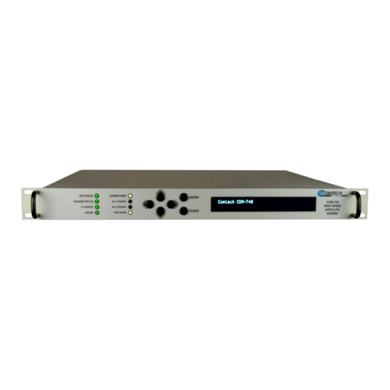
Keypad Indicators Figure 1-4. CDM-740 – Front Panel View Figure 1-4 shows the front panel of the modem. The CDM-740 front panel features (from left): eight LED indicators; a keypad; and a Vacuum Fluorescent Display (VFD): • The LEDs indicate, in a summary fashion, the status of the unit. -
Page 31: Rear Panel
A EIA-232/485 interface for serial modem remote control. 1.3.8 Verification The CDM-740 includes three test modes for rapid verification of the correct function of the unit. When normal operation is again selected, all of the previous values are restored. 1–7... -
Page 32: Flash Upgrading Modem Firmware
In order to permit a lower initial cost, the modem may be purchased with only the desired features enabled. If, at a later date, a user wishes to upgrade the functionality of a modem, Comtech EF Data provides Fully Accessible System Topology (FAST), which permits the purchase and installation of options through special authorization codes loaded into the unit either via the front panel keypad or entered remotely via the remote port located on the modem rear panel. -
Page 33: 1.3.11 Supporting Hardware And Software
1.3.11 Supporting Hardware and Software 1:1 Redundancy Applications The CDM-740 supports 1:1 redundancy applications via use of the optional Comtech EF Data CRS-175L L-Band 1:1 Redundancy Switch. For further information, refer to Appendix C. 1:1 REDUNDANCY in this manual, and the CRS-175L L-Band 1:1 Redundancy Switch Installation and Operation Manual (Comtech EF Data Document Number MN-CRS175). -
Page 34: Summary Of Specifications
CDM-740 Advanced Satellite Modem Revision 0 Introduction MN-CDM740 Summary of Specifications 1.5.1 Transmit / Modulator Modulation QPSK, 8-QAM and 16-QAM Symbol Rate Range 4.8 ksps to 3.00 Msps, programmable in 1 sps steps Data Rate Range 16 kbps to 9.980 Mbps, programmable in 1 bps steps... -
Page 35: Receive / Demodulator
CDM-740 Advanced Satellite Modem Revision 0 Introduction MN-CDM740 1.5.2 Receive / Demodulator L-Band Input 950 to 2150 MHz, Type F female L-Band Input Power Range -25 to -55 dBm Data Decapsulation MPE/IP (ETSI EN 301 192 Multi-Protocol Encapsulation) LDPC+BCH: 5 bit soft decision, proprietary... -
Page 36: Data Interfaces
CDM-740 Advanced Satellite Modem Revision 0 Introduction MN-CDM740 1.5.3 Data Interfaces IF Transmit Output 1 70/140 MHz Transmit Output port BNC (female) L-Band Transmit Output 1 L-Band Transmit Output port Type ‘N’ (female) L-Band Input 1 L-Band Input port Type ‘F’ (female) -
Page 37: Miscellaneous
CDM-740 Advanced Satellite Modem Revision 0 Introduction MN-CDM740 1.5.5 Miscellaneous • 8 LED Indicators: Front Panel Unit Status (Red/Green) Stored Event (Amber) Transmitter On (Green) Rx-1 Traffic (Green) Tx Status (Green) Rx-2 Traffic (Green) Online (Green) Test Mode (Amber) • Tactile keypad – 6 keys (Up, Down, Left, Right, Enter, Clear) •... - Page 38 CDM-740 Advanced Satellite Modem Revision 0 Introduction MN-CDM740 Notes: 1–14...
-
Page 39: Chapter 2. Installation
Inspect shipping containers for damage. If shipping containers are damaged, keep them until the contents of the shipment have been carefully inspected and checked for normal operation. The CDM-740 Advanced Satellite Modem and its Installation and Operation Manual are packaged and shipped in a pre-formed, reusable cardboard carton containing foam spacing for maximum shipping protection. -
Page 40: Mounting
MN-CDM740 Mounting If the CDM-740 is to be mounted in a rack, ensure that there is adequate clearance for ventilation, particularly at the sides. In rack systems where there is high heat dissipation, forced air cooling must be provided by top or bottom mounted fans or blowers. Under no circumstance should the highest internal rack temperature be allowed to exceed 50°C (122°F). -
Page 41: Figure 2-1. Optional Rear-Mounting Support Bracket Installation
CDM-740 Advanced Satellite Modem Revision 0 Installation MN-CDM740 Equipment Rack Rear Mounting Rail #10 Shoulder Screw Support Bracket #10 Flat Washer #10 Flat Washer #10 Bracket Bolt #10 Split Washer #10 Hex Nut Back of unit Figure 2-1. Optional Rear-Mounting Support Bracket Installation... - Page 42 CDM-740 Advanced Satellite Modem Revision 0 Installation MN-CDM740 Notes: 2–4...
-
Page 43: Chapter 3. Rear Panel Connector Pinouts
CONNECTOR PINOUTS Connector Overview The rear panel connectors for the CDM-740 Advanced Satellite Modem, shown here in Figure 3-1, provide all necessary external connections between the modem and other equipment. Table 3-1 on the next page summarizes the connectors provided on the rear panel interface, grouped according to service function. -
Page 44: Table 3-1. Cdm-740 Rear Panel Connectors
CDM-740 Advanced Satellite Modem Revision 0 Rear Panel Connector Pinouts MN-CDM740 Table 3-1. CDM-740 Rear Panel Connectors Connector Name (Ref Des) Connector Type Function Group L-BAND IN 1 IF Rx Input Type ’F’ female (L-Band) Sect. 3.2 L-BAND IN 2 (UNUSED) -
Page 45: If Connections
CDM-740 Advanced Satellite Modem Revision 0 Rear Panel Connector Pinouts MN-CDM740 IF Connections There may be DC voltages present on the Type ‘N’ Rx and Tx IF connectors, up to a maximum of 48 volts. CA UTIO N 3.2.1... -
Page 46: Asi In/Out 1 & 2 Connectors, Bnc (Unused)
The TERM Connector is a standard 6-pin RJ-12 female modular jack. It is used for management of CDM-740 and IP functions using a terminal emulator connected (with the supplied adapter cable) to the Console port. This is a EIA-232 DCE interface. -
Page 47: Remote Control Interface Connector, Db-9M
CDM-740 Advanced Satellite Modem Revision 0 Rear Panel Connector Pinouts MN-CDM740 3.4.3 Remote Control Interface Connector, DB-9M The Remote Control Interface is a 9-pin Type ‘D’ male connector. It is intended for connection to an M&C computer or terminal device, and is user selectable for either EIA-232 or EIA-485. -
Page 48: Power / Ground Connections
CDM-740 Advanced Satellite Modem Revision 0 Rear Panel Connector Pinouts MN-CDM740 Power / Ground Connections 3.5.1 Alternating Current Power Connector A standard, detachable, non-locking, 3-prong power cord (IEC plug) supplies the Alternating Current (AC) power to the modem via this connector. -
Page 49: Chapter 4. Flash Upgrading
• New firmware can be downloaded via the Internet to an external PC. • The upgrade can be performed without opening the CDM-740 by simply connecting the unit to the Ethernet port of a computer. • The firmware update is transferred, via File Transfer Protocol (FTP), to the CDM-740. -
Page 50: Ethernet Ftp Upload Procedure
(verify that the correct firmware number is known – see Step 1); revision letter, if applicable; and release version. The base modem bulk firmware for the CDM-740 is FW-0000279X_V### (where ‘X’ denotes the revision letter, and ‘###’ the firmware version). - Page 51 “dir” command to list the files extracted from the downloaded archive file. 6. Connect the external PC to any one of the four CDM-740 modem 10/100 Ethernet ports, via a hub or a switch, or directly to a PC with a crossover cable.
- Page 52 ) on the front panel Utility Firmware Select keypad to select Latest, #1, or #2, then press ENTER. Verify the new software versions are booting by observing the following messages on the modem display: Comtech CDM-740 Advanced Satellite Modem TPC installed Ver1.1.1 4–4...
-
Page 53: Chapter 5. Front Panel Operation
Indicators Figure 5-1. CDM-740 – Front Panel View The user can fully control and monitor the operation of the CDM-740 Advanced Satellite Modem from the front panel using the keypad and display. Nested menus are used, which display all available options, and prompt the user to carry out a required action. -
Page 54: Front Panel Led Indicators
CDM-740 Advanced Satellite Modem Revision 0 Front Panel Operation MN-CDM740 5.1.1 Front Panel LED Indicators In general, the Alarm relay state will reflect the state of the Front Panel LEDs. For instance, if the Unit Status LED is red, the Unit Alarm relay will be active, etc. -
Page 55: Front Panel Vacuum Fluorescent Display (Vfd)
The message moves from right to left across the screen, then wraps around. The top line of the display identifies the product (i.e., the CDM-740) with the running firmware version or the Circuit ID (which can be entered by the user). -
Page 56: 5.2.2 Cdm-740 Front Panel Menu Matrix
CDM-740 Advanced Satellite Modem Revision 0 Front Panel Operation MN-CDM740 5.2.2 CDM-740 Front Panel Menu Matrix Sect. Menu / Menu Branch Submenu – Available Selections (See Chapt. Sects for nested info) 5.2.1 Opening Screen Select (Main) Menu Configuration Test Monitor Store/Ld Utility ODU FAST... -
Page 57: Select: (Main) Menu
Utility Circuit ID, or Firmware boot image selection. (Outdoor Unit) Permits user to monitor and control a Comtech EF Data RF Transceiver (BUC [Block Up Converter] or LNB [Low-noise Block Down Converter]) , if connected. (Fully Accessible System Topology) Permits user to configure different options, for extended FAST 5.10... -
Page 58: Select: Configuration
CDM-740 Advanced Satellite Modem Revision 0 Front Panel Operation MN-CDM740 SELECT: Configuration CONFIG: Clocks Remote ◄► Misc Use the arrow keys to select from the submenu choices shown, then press ENTER. The ◄ ► submenus available from the Configuration menu branch are as follows:... -
Page 59: Config:) Tx Freq (Frequency)
For Tx frequencies of 950-2150 MHz (L-Band), the permitted level range is –5 to –40 dBm. 5.4.1.4 (CONFIG:) Tx Tx FEC Type: TPC (FPC) This is a ‘status only’ message. The CDM-740 features TPC (Turbo Product Codec) as its sole available Tx FEC type. 5.4.1.5 (CONFIG:) Tx... -
Page 60: Config:) Tx Data
CDM-740 Advanced Satellite Modem Revision 0 Front Panel Operation MN-CDM740 5.4.1.6 (CONFIG:) Tx Data Tx Data Rate: 9980.000 kbps ◄► Tx Symbol Rate: 2851.429 ksps To configure the Tx Data Rate (in kbps), on the top line select the digit of Data Rate to be edited... -
Page 61: Config: Rx
2150.0000 (950-2150) MHz (L-Band). The resolution is 100Hz. 5.4.2.3 (CONFIG:) Rx Rx FEC: LDPC+BCH This is a ‘status only’ message. The CDM-740 features LDPC+BCH (Low-Density Parity Check + Bose, Chaudhuri, and Hocquengham) FEC as its sole available Rx FEC type. 5–9... -
Page 62: Config:) Rx Demod (Demodulation)
CDM-740 Advanced Satellite Modem Revision 0 Front Panel Operation MN-CDM740 5.4.2.4 (CONFIG:) Rx Demod (Demodulation) MODCOD: Auto (Auto,DVB-S) ◄► Framing Mode=Normal (Normal,Short)( On the top line, select the Demodulation type and FEC rate using the arrow keys. Selections ▲ ▼... -
Page 63: Config:) Rx Descram(Bler) (Dvb-S2 Only)
CDM-740 Advanced Satellite Modem Revision 0 Front Panel Operation MN-CDM740 The actual minimum and maximum data rates are dependent on Framing mode, Interface type, Demodulation type and FEC Code Rate. If the user changes any of the higher-priority parameters – causing the data rate to become invalid – the Data Rate is adjusted automatically. The upper range of data rate will also be dictated by the FAST option(s) installed. -
Page 64: Table 5-2. Rx Symbol Rate / Data Rate Ranges - Dvb-S
CDM-740 Advanced Satellite Modem Revision 0 Front Panel Operation MN-CDM740 Table 5-2. Rx Symbol Rate / Data Rate Ranges – DVB-S Symbol Rate (Msps) Data Rate (Mbps) Demodulation FEC Code Code Rate Spectral Efficiency 0.921569 0.921569 41.470588 1.228758 1.228758 55.294118... -
Page 65: Table 5-4. Rx Symbol Rate / Data Rate Range - Dvb-S2 Short Fecframe = 16,200 Bits
CDM-740 Advanced Satellite Modem Revision 0 Front Panel Operation MN-CDM740 Table 5-4. Rx Symbol Rate / Data Rate Range – DVB-S2 Short FECFrame = 16,200 Bits Symbol Rate Data Rate (Mbps) Spectral Data Rate (Mbps) Inner Spectral (Msps) Pilot OFF... -
Page 66: Config: Clocks
In order for this operating parameter to be retained, the user must save this configuration in any one of the 10 available modem configurations (SELECT: Utility Save/Load). Otherwise, when the CDM-740 power is cycled, this IMPORTANT value will be reset. -
Page 67: Config: Remote
CDM-740 Advanced Satellite Modem Revision 0 Front Panel Operation MN-CDM740 5.4.4 CONFIG: Remote Remote Control= Local Serial Ethernet ◄► Select Local, Serial, or Ethernet using the ◄ ► arrow keys, then press ENTER. If Local is selected, then reconfiguration via Serial Remote or Ethernet is not permitted. -
Page 68: Config: Ip
CDM-740 Advanced Satellite Modem Revision 0 Front Panel Operation MN-CDM740 5.4.5.1 (CONFIG:) IP (GE1 / GE2 / MGMT) GE1: Addr/Range Gateway ◄► Link-Config NegoSpeed GE2: Addr/Range Gateway ◄► Link-Config NegoSpeed MANAGEMENT: Addr/Range Gateway ◄► Link-Config NegoSpeed Select Addr/Range, MAC, Gateway, Link-Config, or NegoSpeed using the ◄ ► arrow keys, then press ENTER. -
Page 69: Config:) Ip (Ge1 / Ge2 / Mgmt)
CDM-740 Advanced Satellite Modem Revision 0 Front Panel Operation MN-CDM740 Note the following: Selection Description The port will auto-negotiate the configuration of the port (recommended Auto when the configuration of the port is unknown) 1000 Mb / Full Duplex 1000F... -
Page 70: Config: Misc
CDM-740 Advanced Satellite Modem Revision 0 Front Panel Operation MN-CDM740 5.4.5.3 (CONFIG:) IP (SNMP) Write-Cmty SNMP Write Community (Max 15 chars) ◄► [private To edit the SNMP Write Community string, use the ◄ ► arrow keys to select the character to edit, then use the arrow keys to select the desired character. -
Page 71: Select: Test
Tx BERT State: Off On ◄► Set the Tx BERT State as On or Off using the ◄ ► arrow keys, then press ENTER. When On is selected, the Test Mode LED on the CDM-740 front panel will turn ON. 5.5.2.1 TEST: Pattern Tx BERT Pattern: 2E23-1 2047 ◄►... -
Page 72: Select: Monitor
CDM-740 Advanced Satellite Modem Revision 0 Front Panel Operation MN-CDM740 SELECT: Monitor Monitor: Live-Alarms Stored-Events ◄► Rx-Params IP-Stats Select Live-Alarms, Stored-Events, Rx-Params, or IP-Stats using the ◄ ► arrow keys, then press ENTER 5.6.1 Monitor: Live-Alarms Live Alarms Unit=Unit OK... -
Page 73: Monitor: Stored-Events
CDM-740 Advanced Satellite Modem Revision 0 Front Panel Operation MN-CDM740 5.6.2 Monitor: Stored-Events Stored Events: Clear-All View ◄► Select View or Clear-All using the ◄ ► arrow keys, then press ENTER 5.6.2.1 (Monitor:) Stored-Events Clear-All Clear All Stored Events: No ◄►... -
Page 74: Monitor: Ip-Stats
CDM-740 Advanced Satellite Modem Revision 0 Front Panel Operation MN-CDM740 5.6.4 Monitor: IP-Stats View: Mod/Demod ◄► Clear: Mod Demod GE1/GE2 To view IP operating statistics: From the top line of the Monitor: IP-Stats menu, select Mod/Demod, GE1, or GE2 using the ◄ ► arrow keys, then press ENTER. Examples of the... -
Page 75: Select: Store/Ld
CDM-740 Advanced Satellite Modem Revision 0 Front Panel Operation MN-CDM740 SELECT: Store/Ld Configuration #2: Load Store ◄► AVAILABLE The user can store up to 10 different modem configurations, numbered 0 through 9. Select the configuration location number using the arrow keys, then select Load or Store ▲... -
Page 76: Select: Utility
Press ENTER key to force unit into Standby (1:1 only) The CDM-740 automatically detects the presence of a CRS-175L L-Band 1:1 Redundant Switch. If Utility: 1:1 is selected and this unit is currently online and part of a 1:1 redundant modem pair operating in tandem with a CRS-175L switch, the user is prompted to press ENTER (as indicated above);... -
Page 77: Utilities: 1:N (Unused)
5.8.4 Utilities: 1:N (UNUSED) The CDM-740 presently does not accommodate 1:N redundant operations; therefore, while selectable, this submenu is non-functional. If, however, 1:N is selected from the Utility menu branch – regardless of the presence of a CRS-175L switch – the following error message displays: ... -
Page 78: Utilities: Firmware
TECHNICIAN. IMPORTANT This series of submenus permits the user to view information about the CDM-740 internal firmware. The modem can store two complete firmware images, and the user can select which image will be loaded the next time the unit reboots. -
Page 79: Select: Odu
CDM-740 Advanced Satellite Modem Revision 0 Front Panel Operation MN-CDM740 SELECT: ODU The CDM-740 modem is able to interface with various ODUs (Outdoor Units). These are: • L-Band BUC (Block Upconverter); • L-Band LNB (Low Noise Block Downcoverter). The ODU configuration menus allow the user to set up power supplies, a 10 MHz reference and low/high current alarm thresholds for the BUC and LNB. -
Page 80: Odu: (Buc:) Power
CDM-740 Advanced Satellite Modem Revision 0 Front Panel Operation MN-CDM740 5.9.1.1 ODU: (BUC:) Power BUC Power Enable: ◄► Output Power Enable: Off Select the power parameter to edit using the ◄ ► arrow keys, then use the arrow keys to edit ▲... -
Page 81: Odu: (Lnb) 22K-Tone
CDM-740 Advanced Satellite Modem Revision 0 Front Panel Operation MN-CDM740 • [–] indicates a low side, non-inverting mix. Satellite frequency = LO frequency +/- modem frequency Note: To set the sign for the Terminal Mix, use the ◄ ► arrow keys to navigate to the setting, then use arrow keys to edit the Terminal Mix setting as positive [+] or negative [–]. -
Page 82: 5.10 Select: Fast
On the top line, select the Options, Configure, or Demo-Mode using the ◄ ► arrow keys, then press ENTER. The bottom line provides the CDM-740’s baseboard serial number. This number is required when contacting Comtech EF Data Customer Support to purchase any FAST upgrades. -
Page 83: 5.10.3 Fast: Demo-Mode
Where # represents the selected EEPROM Register # (Word1, Word2, or Word3 on the previous menu): Obtain the FAST code for the new option from Comtech EF Data. Enter the code carefully. Use the ◄ ► arrow keys to move the cursor to each character, then use the arrow keys to edit the ▲... - Page 84 CDM-740 Advanced Satellite Modem Revision 0 Front Panel Operation MN-CDM740 Notes: 5–32...
-
Page 85: Chapter 6. Ethernet Management
MANAGEMENT Introduction The CDM-740 Advanced Satellite Modem is equipped with an RJ-45, 10/100 BaseT Ethernet management interface, labeled FE, that is used for monitor and control purposes. This chapter provides a high-level overview of the functionality provided by this interface, and references other chapters in this manual for further details. -
Page 86: 6.3.1 Management Information Base (Mib) Files
The following MIB files are associated with the CDM-740: MIB File/Name Description FW10874-2-.mib ComtechEFData MIB file gives the root tree for ALL Comtech EF Data products and consists of only the following OID: ComtechEFData Root MIB file Name: comtechEFData Type: MODULE-IDENTITY OID: 1.3.6.1.4.1.6247... -
Page 87: Telnet Interface
CDM-740 Advanced Satellite Modem Revision 0 Ethernet Management MN-CDM740 Telnet Interface The modem provides a Telnet interface for the purpose of Equipment M&C via the standard equipment Remote Control protocol. The Telnet interface Requires user login at the Administrator level and Read/Write level. -
Page 88: Web Server (Http) Interface
The embedded Web Server application provides the user with an easy to use interface to configure and monitor all aspects of the CDM-740. These Web pages have been designed for optimal performance when using Microsoft’s Internet Explorer Version 5.5 or higher (the examples shown use Internet Explorer Version 6.0). -
Page 89: 6.5.3 User Login
Ethernet Management MN-CDM740 6.5.3 User Login To initiate a Web session with the CDM-740 Modem, from the PC type http://xxx.yyy.zzzz (where “xxx.yyy.zzz” represents the IP address of the CDM-740 Advanced Satellite Modem) into the Address area of the Web browser:... -
Page 90: Web Server
Figure 6-1. CDM-740 Advanced Satellite Modem Home (Splash) page Once the valid User Name and Password is accepted, the user will see the CDM-740 Web Server Interface “splash” page. From this top level menu, the user has access to nine (9) navigation tabs: •... -
Page 91: Management
The ‘Management | Main’ page (Figure 6-2) is used to configure the following CDM-740 utility functions: Unit Name The product in use – in this case, the CDM-740 Advanced Satellite Modem – is identified here. System Contact / System Location E-mail and telephone contact information for Comtech EF Data Customer Support are provided here. - Page 92 Once the desired configuration settings have been made in this first section, click [Submit] to save these changes. User Name The User Name for the CDM-740 has a maximum of 15 characters. Password / Confirm Password The admin user may enter a password string of up to 24 characters. Once the desired password string has been typed in the Password box, then re-typed as indicated in the Confirm Password box, click [Submit] as needed to save this change.
-
Page 93: Management | Snmp Page
Management | SNMP Page Figure 6-3. Management | SNMP page The ‘Management | SNMP’ page (Figure 6-3) sets and returns administration information for the CDM-740 Simple Network Management Protocol (SNMP) feature. The Administrator can assign the following attributes: • One SNMP Trap Destination IP Address. -
Page 94: Management | Fast Page
For an overview on FAST, see Sect. 1.3.10 in Chapter 1. INTRODUCTION. • For details on activating FAST features via the CDM-740 front panel, refer to Sect. 5.10 in Chapter 5. FRONT PANEL OPERATION and Appendix B. FAST ACTIVATION FEATURE. -
Page 95: Management | Firmware Page
CDM-740 Advanced Satellite Modem Revision 0 Ethernet Management MN-CDM740 6.5.4.2.4 Management | Firmware Page Figure 6-5. Management | Firmware page The ‘Management | FAST’ page (Figure 6-5) permits the user to view information about the CDM-740 internal firmware. Slot Information This read-only section identifies the two available firmware configurations. -
Page 96: Management | Auto Logout Page
Auto Logout timeframe. A valid user name and password will then be required to open a new session with the CDM-740 Web Server Interface. To configure the Auto Logout feature, enter a value of 1 – 15 minutes into the Logout Time box. -
Page 97: Network
Enter the IP Address CIDR (Classless Inter Domain Routing) Subnet mask using this box. Gateway IP Enter the modem’s IP Gateway Address using this box. Link Configuration Use the dropdown menu to select the line speed and duplex setting on the CDM-740’s FE (Fast Ethernet) interface. The available options are: • •... - Page 98 CDM-740 Advanced Satellite Modem Revision 0 Ethernet Management MN-CDM740 Negotiated Link Mode The read-only actual negotiated line speed and duplex setting for the FE (Fast Ethernet) interface is displayed here. The viewable settings are: • 100 BaseT / Full Duplex •...
-
Page 99: Network | Ge-1 And
CDM-740 Advanced Satellite Modem Revision 0 Ethernet Management MN-CDM740 6.5.4.3.2 Network | GE-1 and GE-2 Pages Figure 6-8. Network | GE-1 and GE-2 pages The ‘Network | GE1’ and ‘Network | GE2’ pages (Figure 6-8) permit the user to configure the communication settings for the unit’s two 10/100/1000 BaseT Gigabit Ethernet traffic ports. -
Page 100: Demod (Demodulator) | Tuner-1 Page
DEMOD (Demodulator) | Tuner-1 Page Figure 6-9. DEMOD | Tuner-1 page The ‘DEMOD | Tuner-1’ page (Figure 6-9) permits the user to configure CDM-740 demodulator operations. Note that, for any configuration item requiring text entry, a reference to the operational ranges for that field is provided to the right of that text box. - Page 101 CDM-740 Advanced Satellite Modem Revision 0 Ethernet Management MN-CDM740 Selections are as follows: • • • Auto DVB-S2 QPSK 3/4 DVB-S2 16-APSK 2/3 • • • DVB-S QPSK 1/2 DVB-S2 QPSK 5/6 DVB-S2 16-APSK 3/4 • • • DVB-S QPSK 2/3...
-
Page 102: Decap (Decapsulator) | Tuner-1 Page
6.5.4.5 DECAP (Decapsulator) | Tuner-1 Page Figure 6-10. Decapsulator | Tuner-1 page The ‘DECAP | Tuner-1’ page (Figure 6-10) permits the user to configure CDM-740 decapsulator operations. Current Routes – Tuner 1 This section permits the user to view, modify, or delete previously-created Rx Routes. - Page 103 MPE/IP data to be extracted from the transport stream and sent to the CDM-740 CPU. Once a valid PID value is configured and data is found on a transport stream, the data is decapsulated and delivered to the traffic port.
-
Page 104: Mod (Modulator) Page
MOD (Modulator) Page Figure 6-11. Modulator page The ‘MOD’ page (Figure 6-11) permits the user to configure CDM-740 modulator operations. Note that, for any configuration item requiring text entry, a reference to the operational ranges for that field is provided to the right of that text box. - Page 105 CDM-740 Advanced Satellite Modem Revision 0 Ethernet Management MN-CDM740 Tx FEC Code Rate Use the dropdown menu to select the available Tx FEC Code Rate as 1/2, 3/4, 7/8, or 0.95. Tx Scrambler Use the dropdown menu to select the Tx Scrambler as Off, Normal, or IESS-315.
- Page 106 CDM-740 Advanced Satellite Modem Revision 0 Ethernet Management MN-CDM740 BUC Section BUC LO Freq (MHz) Enter the BUC’s lockout frequency, in MHz. The valid LO range is 3000 to 65000 MHz. BUC Power Enable Use the dropdown menu to select the BUC Power Enable as either Off or On.
-
Page 107: Statistics
CDM-740 Advanced Satellite Modem Revision 0 Ethernet Management MN-CDM740 6.5.4.7 Statistics Pages The pages available under the ‘Statistics’ tab provide the user access to status and operational statistics windows for the Modulator, the Tuner, and the Ethernet traffic ports. 6.5.4.7.1 Statistics | Summary Page Figure 6-12. -
Page 108: Statistics | Tuner-1 Page
CDM-740 Advanced Satellite Modem Revision 0 Ethernet Management MN-CDM740 6.5.4.7.2 Statistics | Tuner-1 Page Figure 6-13. Statistics | Tuner-1 page The ‘Statistics | Tuner-1’ page (Figure 6-13) provides the user with a read-only status windows pertaining to the active operational statistics for Tuner-1 and active PIDs. -
Page 109: Statistics | Ge-1 And
CDM-740 Advanced Satellite Modem Revision 0 Ethernet Management MN-CDM740 6.5.4.7.3 Statistics | GE-1 and GE-2 Pages Figure 6-14. Statistics | GE-1 and GE-2 pages The ‘Statistics | GE-1’ and ‘Statistics | GE-2’ pages (Figure 6-14) provide the user with read- only status windows pertaining to the aggregate operational statistics for the unit’s two... -
Page 110: Statistics | Modulator Page
CDM-740 Advanced Satellite Modem Revision 0 Ethernet Management MN-CDM740 Current Tx (Mbps): Most recent transmitted data rate (in megabits per second). Current Rx (Mbps): Most recently received data rate (in megabits per second). Maximum Tx (Mbps): Peak transmitted data rate (in megabits per second). -
Page 111: Monitor Page
CDM-740 Advanced Satellite Modem Revision 0 Ethernet Management MN-CDM740 6.5.4.8 Monitor Page Figure 6-16. Monitor page The ‘Monitor’ page (Figure 6-16) provides a read-only window that displays any events and alarms as logged by the unit during normal operation. As each event or alarm is logged, it is date- and time-stamped. A description for each entry follows. -
Page 112: Utility Page
Figure 6-17. Utility page The ‘Utility’ page (Figure 6-16) provides the user with the means to load or save a modem configuration, and control operation of the CDM-740 as part of a 1:1 Redundancy setup. Save / Load Configuration This section allows the user to save, then load (recall) up to 10 configuration sets. - Page 113 CDM-740 Advanced Satellite Modem Revision 0 Ethernet Management MN-CDM740 a switchover, so the unit will then be in ‘Standby’ mode. The command is always executed by the unit, regardless of whether it is stand-alone, or in a 1:1 pair. Tuner 1 Constellation The Utility page provides access to a demodulator constellation for the Tuner-1 I&Q.
- Page 114 CDM-740 Advanced Satellite Modem Revision 0 Ethernet Management MN-CDM740 Notes: 6–30...
-
Page 115: Appendix A. Remote Control
Overview This appendix describes the protocol and message command set for remote monitor and control (M&C) of the CDM-740 Satellite Modem. The electrical interface is an EIA-232 connection (for the control of a single device), and data is transmitted in asynchronous serial form, using ASCII characters. Control and status information is transmitted in packets, of variable length, in accordance with the structure and protocol defined in later sections. -
Page 116: Packet Structure
CDM-740 Advanced Satellite Modem Revision 0 Remote Control MN-CDM740 Packet Structure Controller-to-Target Start of Target Address De- Instruction Code Optional End of Packet Packet Address limiter Code Qualifier Arguments < = or ? Carriage Return ASCII code ASCII code ASCII codes... -
Page 117: Instruction Code Qualifier
CDM-740 Advanced Satellite Modem Revision 0 Remote Control MN-CDM740 message, should it be displayed in its raw ASCII form. Only upper case alphabetic characters may be used (A-Z, ASCII codes 65 - 90). A.4.5 Instruction Code Qualifier This single character further qualifies the preceding instruction code. Code Qualifiers obey the following rules: 1. -
Page 118: Optional Message Arguments
CDM-740 Advanced Satellite Modem Revision 0 Remote Control MN-CDM740 The ∼ code is only used as follows: ∼ If a message was sent via a local modem to a distant end device or ODU, the (ASCII Code 126) message was transmitted transparently through the local modem. In the event of the distant-end device not responding, the local modem would generate a response. - Page 119 CDM-740 Advanced Satellite Modem Revision 0 Remote Control MN-CDM740 Remote Commands and Queries Column ‘C’ = Command; Column ‘Q’ = Query; columns marked ‘X’ designate instruction code as Command only, Query only, or Command/Query. Index Notes: Where annotation reads X = Only in IP-ACM mode –...
-
Page 120: Tx Parameters
CDM-740 Advanced Satellite Modem Revision 0 Remote Control MN-CDM740 A.5.1 Tx Parameters Priority System: TIT (Highest priority), TFT, TMD, TCR, TDR, and TSR (Lowest Priority), indicated by shading. Any change to a higher priority parameter can override any of the parameters of lower priority. - Page 121 CDM-740 Advanced Satellite Modem Revision 0 Remote Control MN-CDM740 Command Query Parameter Number of Response to (Instruction Description of Arguments (Instruction Response to Query Type Arguments Command & Qualifier) & Qualifier) Command or Query. Tx FEC Code TCR= 1 byte, value of...
- Page 122 CDM-740 Advanced Satellite Modem Revision 0 Remote Control MN-CDM740 Command Query Parameter Number of Response to (Instruction Description of Arguments (Instruction Response to Query Type Arguments Command & Qualifier) & Qualifier) Command or Query. Tx Power TPL= 4 bytes TPL= TPL? TPL=sxx.x...
-
Page 123: Rx Parameters
CDM-740 Advanced Satellite Modem Revision 0 Remote Control MN-CDM740 A.5.2 Rx Parameters Priority System: RF1 (Highest priority) and RL1 (Lowest Priority), indicated by shading. Any change to a higher priority parameter can override any of the parameters of lower priority. - Page 124 CDM-740 Advanced Satellite Modem Revision 0 Remote Control MN-CDM740 Command Query Parameter Number of Response to (Instruction Description of Arguments (Instruction Response to Query Type Arguments Command & Qualifier) & Qualifier) Command or Query. Rx 1 RC1= 2 byte, value of...
- Page 125 CDM-740 Advanced Satellite Modem Revision 0 Remote Control MN-CDM740 Command Query Parameter Number of Response to (Instruction Description of Arguments (Instruction Response to Query Type Arguments Command & Qualifier) & Qualifier) Rx 1 Gold Command or Query. RG1= RG1= 6 bytes...
-
Page 126: Unit Parameters
Command or Query. AU1= AU1? AU1=x Unicast or 1 AU1? (see Description of Selects whether the CDM-740 allows unicast traffic from the Rx 1 Tuner, AU1* Arguments) where: AU1# 0=Off (default) 1=On Example: AU1=1 (allow unicast traffic from Rx 1) - Page 127 FM1= Sat MAC or 1 FM1? (see Description of When the Satellite MAC is defined, the CDM-740 only routes Unicast FM1* Arguments) traffic that is specifically addressed to the Satellite MAC, where: FM1# 0=Off, do not filter on the Sat MAC (default) 1=On This value does not affect the processing of multicast packets.
- Page 128 CDM-740 Advanced Satellite Modem Revision 0 Remote Control MN-CDM740 Command Query Parameter Number of Response to (Instruction Description of Arguments (Instruction Response to Query Type Arguments Command & Qualifier) & Qualifier) GE1 Address IG1= 18 bytes Command or Query. IG1= IG1? IG1=xxx.xxx.xxx.xxx.yy...
- Page 129 CDM-740 Advanced Satellite Modem Revision 0 Remote Control MN-CDM740 Command Query Parameter Number of Response to (Instruction Description of Arguments (Instruction Response to Query Type Arguments Command & Qualifier) & Qualifier) Management IPG= 15 bytes Command or Query. IPG= IPG? IPG=xxx.xxx.xxx.xxx...
- Page 130 Command or Query. RD1= RD1? RD1=x Default or 1 RD1? (see Description of When enabled, all incoming Unicast traffic not destined to the CDM-740 Gateway RD1* Arguments) local network subnet is directed to the configured default Gateway IP, RD1# where: 0=Off (default)
- Page 131 CDM-740 Advanced Satellite Modem Revision 0 Remote Control MN-CDM740 Command Query Parameter Number of Response to (Instruction Description of Arguments (Instruction Response to Query Type Arguments Command & Qualifier) & Qualifier) Retrieve next 80 bytes Query only. RNE? RNE=[CR]ABCddmmyyhh 5 unread...
- Page 132 CDM-740 Advanced Satellite Modem Revision 0 Remote Control MN-CDM740 Command Query Parameter Number of Response to (Instruction Description of Arguments (Instruction Response to Query Type Arguments Command & Qualifier) & Qualifier) SNMP SSL= 254 bytes, Command or Query. SSL = SSL? SSL =x [1..254]...
-
Page 133: Bulk Configuration Strings
1 = Image #1 Firmware Information 2 = Image #2 Firmware Information Example: FRW=1 Fw/12864-,1.1.1,04/01/07 Query only. Serial Number 9 bytes SNO? SNO=xxxxxxxxx (see Description of Returns the CDM-740’s 9-digit serial number. Arguments) Example: SNO=176500143 Query only. Software 8 bytes SWR? SWR=xx.xx.xx Revision (see description... - Page 134 CDM-740 Advanced Satellite Modem Revision 0 Remote Control MN-CDM740 Command Response Query Parameter Number of (Instruction Description of Arguments (Instruction & Response to Query Type Arguments & Qualifier) Command Qualifier) Equipment ID 36 bytes Query only. EID? EID=AAAABssssCDEF GHIsssssssssssssssss Returns the equipment ID and installed options, where:...
-
Page 135: Modem Performance Information
CDM-740 Advanced Satellite Modem Revision 0 Remote Control MN-CDM740 A.5.6 Modem Performance Information Command Response Query Parameter Number of (Instruction Description of Arguments (Instruction & Response to Query Type Arguments & Qualifier) Command Qualifier) Query only. Rx BER 5 bytes... - Page 136 CDM-740 Advanced Satellite Modem Revision 0 Remote Control MN-CDM740 Command Response Query Parameter Number of (Instruction Description of Arguments (Instruction & Response to Query Type Arguments & Qualifier) Command Qualifier) Faults and d = Rx 2 Traffic status (future): 0=Rx Traffic OK Status (cont.)
-
Page 137: Buc Parameters (L-Band Device
CDM-740 Advanced Satellite Modem Revision 0 Remote Control MN-CDM740 A.5.7 BUC Parameters (L-Band Device) Command Query Parameter Number of Response to (Instruction Description of Arguments (Instruction & Response to Query Type Arguments Command & Qualifier) Qualifier) BCH= 4 bytes Command or Query. - Page 138 CDM-740 Advanced Satellite Modem Revision 0 Remote Control MN-CDM740 Notes: A–24...
-
Page 139: Appendix B. Fast Activation Procedure
In order to permit a lower initial cost, the modem may be purchased with only the desired features enabled. If, at a later date, a user wishes to upgrade the functionality of a modem, Comtech EF Data provides Fully Accessible System Topology (FAST), which permits the purchase and installation of options through special authorization codes loaded into the unit either via the front panel keypad or entered remotely via the remote port located on the modem rear panel. -
Page 140: Fast Activation Procedure
FAST Activation Procedure The FAST options are linked to three option registers – Word1, Word2, and Word3. When an unlock FAST code is obtained from Comtech EF Data it will be for a specific register. B.2.1 Serial Number Obtain the Modem serial number as follows: a) From the front panel main menu, then press [ENTER]. -
Page 141: Appendix C. 1:1 Redundancy
Overview Figure C-1. CRS-175L L-Band 1:1 Redundancy Switch For 1:1 redundancy applications, the CDM-740 Advanced Satellite Modem is supported by the Comtech EF Data CRS-175L L-Band 1:1 Redundancy Switch (Figure C-1). The purpose of this appendix is to provide a brief overview of the CRS-175L’s functionality in a CDM-740 1:1 redundant configuration. -
Page 142: Introduction
Figure C-2 shows the block diagram for a 1:1 redundancy configuration for L-Band simplex or L-Band full duplex operation. using a CDM-740 modem pair with a CRS-175L switch. Figure C-2. CRS-175L – 1:1 Redundancy (L-Band Simplex or Full Duplex Operation) The CRS-175L switch supports 1:1 redundancy in the following manner: •... -
Page 143: 1:1 Redundancy Setup
(non-revertive). CDM-740 1:1 Redundancy Setup In order to avoid damage to the CDM-740 modems and the CRS-175L switch, it is important for the user to follow this sequence of configuration: First, ensure that the CDM-740 Satellite Modems have been properly set up •... -
Page 144: Crs-175L
CRS-175L L-Band 1:1 Redundancy Switch Installation and Operation Manual (Comtech EF Data Document Number MN-CRS175) for complete cabling information. C.3.1.1 User CRS-175L CDM-740 IF and Control Cabling Figure C-3. User CRS-175L CDM-740 IF and Control Cabling Example C–4... -
Page 145: User Data Interface Cabling Connections
CDM-740 Advanced Satellite Modem Revision 0 1:1 Redundancy MN-CDM740 C.3.1.2 CDM-740 User Data Interface Cabling Connections Figure C-4. User CRS-175L CDM-740 IF and Control Cabling Example C–5... -
Page 146: 1:1 Redundancy Operations Via The Cdm-740
C.3.2.1 Redundancy Operation via the Front Panel The user can control 1:1 redundant operation via the CDM-740 front panel, using the keypad and display. Nested menus are used, which display all available options, and prompt the user to carry out a required action. - Page 147 Press ENTER key to force unit into Standby (1:1 only) The CDM-740 automatically detects the presence of a CRS-175L L-Band 1:1 Redundant Switch. If Utility: 1:1 is selected and this unit is currently online and part of a 1:1 redundant modem pair operating in tandem with a CRS-175L switch, the user is prompted to press ENTER (as indicated above);...
-
Page 148: Figure C-6. Cdm-740 Web Server Interface Utility Page
Figure C-6. CDM-740 Web Server Interface Utility page From the CDM-740 Web Server Interface the ‘Utility’ page (Figure C-6) provides the user with the means to load or save a modem configuration, and control operation of the CDM-740 as part of a 1:1 Redundancy setup. -
Page 149: Metric Conversions
METRIC CONVERSIONS Units of Length Unit Centimeter Inch Foot Yard Mile Meter Kilometer Millimeter 1 centimeter — 0.3937 0.03281 0.01094 6.214 x 10 0.01 — — 1 inch 2.540 — 0.08333 0.2778 0.254 — 25.4 1.578 x 10 1 foot 30.480 12.0 —... - Page 150 2114 85281 WEST TH STREET TEMPE ARIZONA 480 • 333 • 2200 PHONE 480 • 333 • 2161...
Need help?
Do you have a question about the CDM-740 and is the answer not in the manual?
Questions and answers