Table of Contents
Advertisement
Quick Links
CDM-750
Advanced High-Speed Trunking Modem
Installation and Operation Manual
For Firmware Version 1.6.1 or higher
Part Number MN-CDM750
Revision 2
IMPORTANT NOTE: The information contained in this document supersedes all previously published
information regarding this product. Product specifications are subject to change without prior notice.
Advertisement
Table of Contents

Subscribe to Our Youtube Channel
Related Manuals for Comtech EF Data CDM-750


Summary of Contents for Comtech EF Data CDM-750
- Page 1 CDM-750 Advanced High-Speed Trunking Modem Installation and Operation Manual For Firmware Version 1.6.1 or higher Part Number MN-CDM750 Revision 2 IMPORTANT NOTE: The information contained in this document supersedes all previously published information regarding this product. Product specifications are subject to change without prior notice.
- Page 2 Copyright © 2012 Comtech EF Data. All rights reserved. Printed in the USA. Comtech EF Data, 2114 West 7th Street, Tempe, Arizona 85281 USA, 480.333.2200, FAX: 480.333.2161...
-
Page 3: Table Of Contents
TABLE OF CONTENTS TABLE OF CONTENTS ......................III TABLES ............................. XII FIGURES ..........................XIII PREFACE ..........................XV About this Manual .......................... x v Reporting Comments or Suggestions Concerning this Manual ................ xv Conventions and References ....................... x v Patents and Trademarks ............................ xv Warnings, Cautions, and Notes .......................... xv Examples of Multi‐Hazard Notices .......................... xvi Recommended Standard Designations ........................ xvi Metric Conversion .............................. xvi Safety and Compliance ........................ x vi Electrical Safety and Compliance .......................... xvi Electrical Installation .............................. xvii Operating Environment ... - Page 4 CDM-750 Advanced High-Speed Trunking Modem Revision 2 Table of Contents MN-CDM750 1.2 CDM‐750 Functional Description ................... 1–1 1.3 CDM‐750 Features ........................ 1–5 1.3.1 Physical Description .......................... 1–6 1.3.2 Dimensional Envelope .......................... 1–7 1.3.3 CDM‐750 External Physical Features .................... 1–8 1.3.3.1 Front Panel ........................ 1–8 1.3.3.2 Rear Panel ......................... 1–9 1.3.3.2.1 Rear Panel Standard Features.................. 1–9 1.3.3.2.2 Rear Panel Optional Features ................... 1–10 1.4 CDM‐750 Specifications ...................... 1–11 1.4.1 System Specifications ......................... 1–11 1.4.2 ...
- Page 5 CDM-750 Advanced High-Speed Trunking Modem Revision 2 Table of Contents MN-CDM750 3.2.1.1 Rx Connectors ........................ 3–7 3.2.1.2 Tx Connectors ........................ 3–7 3.2.1.3 J10 | TX MON Connector, Type ‘SMA’ ................ 3–7 3.2.2 Utility Connector Group ........................ 3–8 3.2.2.1 J1 | ALARM Connector, DB‐15M .................. 3–8 3.2.2.2 J2 | REDUNDANCY Connector, DB‐9F ................ 3–9 3.2.2.3 J3 | REMOTE Connector, DB‐9M .................. 3–9 3.2.2.4 J4 | MGMT Connector, RJ‐45F .................. 3–10 3.2.2.5 J8 | EXT REF Connector, BNC .................. 3–10 3.2.3 Terrestrial Data Connector Group ..................... 3–11 3.2.3.1 J5 | DATA, J6 | DATA Connections, RJ‐45F .............. 3–11 3.2.3.2 J7 | OPTICAL Connection, 1000Base‐SX Cage .............. 3–12 ...
- Page 6 CDM-750 Advanced High-Speed Trunking Modem Revision 2 Table of Contents MN-CDM750 5.2.2.1.1 Single Stream Mode vs. MultiStream Mode Operation .......... 5–8 5.2.2.1.2 (CONFIG) INTF: PIICX = G703 .................. 5–10 5.2.2.1.3 (CONFIG) INTF: PIICX = OC3 .................. 5–14 5.2.2.1.4 (CONFIG) INTF: GBEIX .................... 5–17 5.2.2.1.5 (CONFIG) INTF: Optical .................... 5–20 5.2.2.2 CONFIG: Tx ........................ 5–20 5.2.2.2.1 (CONFIG) Tx: IF ...................... 5–20 5.2.2.2.2 (CONFIG) Tx: Freq (Frequency) ................. 5–20 5.2.2.2.3 (CONFIG) Tx: Power .................... 5–21 5.2.2.2.4 (CONFIG) Tx: Frame .................... 5–21 5.2.2.2.5 (CONFIG) Tx: Mod (Modulation) ................ 5–22 5.2.2.2.6 (CONFIG) Tx: Data ..................... 5–22 ...
- Page 7 CDM-750 Advanced High-Speed Trunking Modem Revision 2 Table of Contents MN-CDM750 5.2.4.1 Monitor: Live‐Alarms ...................... 5–45 5.2.4.2 Monitor: Stored‐Events.................... 5–46 5.2.4.3 Monitor: ACM ......................... 5–46 5.2.4.4 Monitor: Rx‐Params (Rx Parameters) ................ 5–46 5.2.4.5 Monitor: CnC (Carrier‐in‐Carrier Parameters) .............. 5–47 5.2.4.6 Monitor: Stats (Statistics) .................... 5–47 5.2.4.6.1 Monitor: Stats IP .................... 5–48 5.2.4.6.2 Monitor: Stats BasebandFraming ............... 5–49 5.2.4.6.3 Monitor: Stats Compression ................ 5–50 5.2.4.7 Monitor: Buffer ....................... 5–51 5.2.5 SELECT: Info (Information) ......................... 5–52 5.2.5.1 Info: ID .......................... 5–52 ...
- Page 8 CDM-750 Advanced High-Speed Trunking Modem Revision 2 Table of Contents MN-CDM750 CHAPTER 6. ETHERNET-BASED REMOTE PRODUCT MANAGEMENT ......6–1 6.1 Introduction ......................... 6–1 6.2 Ethernet Management Interface Protocols ................ 6–2 6.3 SNMP Interface ........................ 6–2 6.3.1 Management Information Base (MIB) Files .................. 6–3 6.3.2 SNMP Community Strings ........................ 6–3 6.3.3 SNMP Traps ............................ 6–4 6.4 Telnet Interface ........................ 6–5 6.4.1 Telnet Operation via HyperTerminal .................... 6–5 6.5 ...
- Page 9 CDM-750 Advanced High-Speed Trunking Modem Revision 2 Table of Contents MN-CDM750 6.5.4.7 RxGraph pages (Minutes / Hours / Days) ................ 6–33 CHAPTER 7. SERIAL-BASED REMOTE PRODUCT MANAGEMENT ........ 7–1 7.1 Introduction ......................... 7–1 7.2 EIA‐485 .......................... 7–2 7.3 EIA‐232 .......................... 7–3 7.4 Remote Commands and Queries Overview ................ 7–3 7.4.1 Basic Protocol ............................ 7–3 7.4.2 Packet Structure ............................ 7–3 ...
- Page 10 CDM-750 Advanced High-Speed Trunking Modem Revision 2 Table of Contents MN-CDM750 B.2 Optional PIIC Modules ...................... B–4 B.2.1 G.703 E3/T3/STS‐1 PIIC Module (CEFD P/N PL‐0000795) .............. B–4 B.2.1.1 G.703 E3/T3/STS‐1 PIIC Module Summary of Specifications .......... B –5 B.2.1.1.1 General Specifications .................... B –5 B.2.1.1.2 Interface Specifications .................... B –5 B.2.2 STM‐1 Copper PIIC Module Kit (CEFD P/N KT‐0000255) .............. B–6 B.2.2.1 STM‐1 Copper PIIC Module Summary of Specifications ........... B –7 B.2.3 OC‐3 Single/Multi Mode PIIC Module Kits (CEFD P/N KT‐000025X) .......... B–8 B.2.3.1 OC‐3 Single/Multi Mode PIIC Module Summary of Specifications ........ B –9 ...
- Page 11 CDM-750 Advanced High-Speed Trunking Modem Revision 2 Table of Contents MN-CDM750 D.4.2 Margin Requirements ........................... D –9 D.4.3 Carrier‐in‐Carrier Latency ........................ D –9 D.4.4 Carrier‐in‐Carrier and Adaptive Coding and Modulation (ACM) ............. D –10 D.4.5 Carrier‐in‐Carrier Link Design ...................... D –10 D.4.6 Symmetric Data Rate Link ........................ D –11 D.4.6.1 Asymmetric Data Rate Link .....................D–13 D.4.6.2 Power Limited Links ......................D–14 D.4.7 ...
-
Page 12: Tables
CDM-750 Advanced High-Speed Trunking Modem Revision 2 Table of Contents MN-CDM750 G.3.4 BER Testing ............................ G –4 G.3.5 ACM Modulator Status ......................... G –4 G.3.6 ACM Demodulator Status ........................ G –4 G.3.7 CnC Status .............................. G –4 APPENDIX H. FEC (FORWARD ERROR CORRECTION) ..........H–1 H.1 ... -
Page 13: Figures
CDM-750 Advanced High-Speed Trunking Modem Revision 2 Table of Contents MN-CDM750 FIGURES Figure 1‐1. CDM‐750 Advanced High‐Speed Trunking Modem .............. 1–1 Figure 1‐2. CDM‐750 Dimensional Envelope .................... 1–7 Figure 1‐3. CDM‐750 Front Panel View ..................... 1–8 Figure 1‐4. CDM‐750 Rear Panel View ...................... 1–9 Figure 1‐5. 70/140 MHz Input Level vs. Symbol Rate ................ 1–13 Figure 1‐6. L‐Band Input Level vs. Symbol Rate .................. 1–14 Figure 2‐1. Unpacking and Inspecting the Shipment ................ 2–1 Figure 2‐2. Installing into a Rack Enclosure .................... 2–3 Figure 2‐3. Installing the Optional Rear‐Mounting Support Brackets Kit .......... 2–4 Figure 2‐4. Installing the Optional Bearingless Rack Slide Set .............. 2–6 Figure 3‐1. Coaxial Connector Examples .................... 3–1 Figure 3‐2. D‐Subminiature Connector Examples .................. 3–3 Figure 3‐3. CDM‐750 Cabling Connections .................... 3–5 Figure 3‐4. Typical SFP Module Installation .................... 3–12 Figure 3‐5. Typical PIIC Module Installation ................... 3–13 Figure 3‐6. CDM‐750 Chassis Ground Interface .................. 3–14 ... - Page 14 CDM-750 Advanced High-Speed Trunking Modem Revision 2 Table of Contents MN-CDM750 Figure B‐1. Typical PIIC Module Installation ..................... B –2 Figure B‐2. G.703 E3/T3/STS‐1 PIIC Module ..................... B –4 Figure B‐3. G.703 E3/T3/STS‐1 PIIC Module Block Diagram .............. B –4 Figure B‐4. G.703 E3/T3/STS‐1 PIIC Module Panel Connectors .............. B –4 Figure B‐5. STM‐1 Copper PIIC Module Kit (CEFD P/N KT‐0000255) ............ B –6 Figure B‐6. STM‐1 Copper PIIC Module – SFP Installation ................ B –6 Figure B‐7. OC‐3 Single Mode or Multi Mode PIIC Module Kit (CEFD P/N KT‐000025X) ...... B –8 Figure B‐8. OC‐3 Single Mode or Multi Mode PIIC Module – SFP Installation .......... B –8 Figure C‐1. Downlink Margin vs. Average Link Availability ............... C –4 ...
-
Page 15: Preface
PREFACE About this Manual This manual provides installation and operation information for the Comtech EF Data CDM‐750 Advanced High‐Speed Trunking Modem. This is an informational document intended for the persons responsible for the operation and maintenance of the CDM‐750. Reporting Comments or Suggestions Concerning this Manual Comtech EF Data welcomes comments and suggestions regarding the content and design of this manual. Contact the Comtech EF Data Technical Publications Department: TechnicalPublications@comtechefdata.com Conventions and References Patents and Trademarks See all of Comtech EF Data's Patents and Patents Pending at http://patents.comtechefdata.com. Comtech EF Data acknowledges that all trademarks are the property of the trademark owners. • ®... -
Page 16: Examples Of Multi-Hazard Notices
CDM-750 Advanced Higuh-Speed Trunking Modem Revision 2 Preface MN-CDM750 A NOTE gives important information about a task or the equipment. A REFERENCE directs the user to additional information about a task or the equipment. Examples of Multi-Hazard Notices ... -
Page 17: Electrical Installation
CDM-750 Advanced Higuh-Speed Trunking Modem Revision 2 Preface MN-CDM750 Electrical Installation CONNECT THE UNIT TO A POWER SYSTEM THAT HAS SEPARATE GROUND, LINE AND NEUTRAL CONDUCTORS. DO NOT CONNECT THE UNIT WITHOUT A DIRECT CONNECTION TO GROUND. Sect 3.3 CDM‐750 Ground and Power Connections Operating Environment DO NOT OPERATE THE UNIT IN ANY OF THESE EXTREME OPERATING CONDITIONS: • AMBIENT TEMPERATURES LESS THAN 0° C (32° F) OR MORE THAN 50° C ... -
Page 18: European Union Low Voltage Directive (Lvd) (2006/95/Ec)
CDM-750 Advanced Higuh-Speed Trunking Modem Revision 2 Preface MN-CDM750 • EN 61000‐3‐3 – Voltage Fluctuations and Flicker. • Federal Communications Commission Federal Code of Regulation FCC Part 15, Subpart B. TO ENSURE THAT THE UNIT COMPLIES WITH THESE STANDARDS, OBEY THESE INSTRUCTIONS: • Use coaxial cable that is of good quality for connections to the L‐Band Type ‘N’ Rx (receive) female connector. • Use Type 'D' connectors that have back‐shells with continuous metallic shielding. ... -
Page 19: European Union Telecommunications Terminal Equipment Directive (91/263/Eec)
CDM-750 Advanced Higuh-Speed Trunking Modem Revision 2 Preface MN-CDM750 European Union Telecommunications Terminal Equipment Directive (91/263/EEC) In accordance with the European Union Telecommunications Terminal Equipment Directive 91/263/EEC, the unit should not be directly connected to the Public Telecommunications Network. CE Mark Comtech EF Data declares that the unit meets the necessary requirements for the CE Mark. ... -
Page 20: Exclusive Remedies
CDM-750 Advanced Higuh-Speed Trunking Modem Revision 2 Preface MN-CDM750 The warranty does not apply to any product or parts thereof where the serial number or the serial number of any of its parts has been altered, defaced, or removed. The warranty does not cover damage or loss incurred in transportation of the product. The warranty does not cover replacement or repair necessitated by loss or damage from any cause beyond the control of Comtech EF Data Corporation, such as lightning or other natural and weather related events or wartime environments. The warranty does not cover any labor involved in the removal and or reinstallation of warranted equipment or parts on site, or any labor required to diagnose the necessity for repair or replacement. The warranty excludes any responsibility by Comtech EF Data Corporation for incidental or consequential damages arising from the use of the equipment or products, or for any ... -
Page 21: Getting Help
CDM-750 Advanced Higuh-Speed Trunking Modem Revision 2 Preface MN-CDM750 Getting Help Review the Warranty Policy before contacting Comtech EF Data Technical Support or Customer Service. Contacting Comtech EF Data Contact Comtech EF Data for: • Technical Support – Product support or training. • Customer Service – Information on returning an in‐warranty or out‐of‐warranty product for upgrade or repair. Be prepared to provide the product model number and its serial ... -
Page 22: Returning A Product For Upgrade Or Repair
CDM-750 Advanced Higuh-Speed Trunking Modem Revision 2 Preface MN-CDM750 Returning a Product for Upgrade or Repair Step Task Go to the Comtech EF Data Home page (http://www.comtechefdata.com). From the 1 SUPPORT column at the bottom of the page, select the Service hyperlink, and read the Return Material Authorization section in its entirety. 2 Request a Return Material Authorization Number: • On the Comtech EF Data Home page: From the SUPPORT column at the bottom of the page, select the RMA Request hyperlink; OR • On the Comtech EF Data Support page: Click [Send RMA Request]; OR • On the Comtech EF Data Service page: Select the Return Material Authorizaion hyperlink; ... -
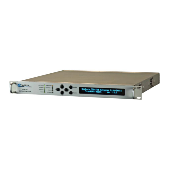
Page 23: Chapter 1. Introduction
Figure 1-1. CDM-750 Advanced High-Speed Trunking Modem The CDM‐750 Advanced High‐Speed Trunking Modem (Figure 1‐1) is intended for network operators, enterprise users, and service providers requiring maximum throughput while using minimal satellite resources in point‐to‐point links. The CDM‐750 combines DVB‐S2 modulation ... - Page 24 CDM-750 Advanced High-Speed Trunking Modem Revision 2 Introduction MN-CDM750 • Supports reception and transmission of IP data over satellite links via two fundamentally different types of interface – IF and data: o The IF interface provides a bidirectional link with the satellite via the uplink and downlink equipment. o The data interface is a bidirectional path that connects the customer’s equipment ...
-
Page 25: Appendix H. Fec (Forward Error Correction
CDM-750 Advanced High-Speed Trunking Modem Revision 2 Introduction MN-CDM750 DVB‐S2 Receiver: The CDM‐750 supports DVB‐S2 QPSK, 8PSK, 16APSK, and 32APSK modulation/ demodulation up to 63 Msps with receive data rates up to 169 Mbps depending on the modulation type and code rate. In DVB‐S2 operation, the receiver operates in the CCM and ACM modes. The receiver ... -
Page 26: Table 1-1. Fast And Fast-Accessible Hardware Options
CDM-750 Advanced High-Speed Trunking Modem Revision 2 Introduction MN-CDM750 Table 1-1. FAST and FAST-accessible Hardware Options Description and Comments Option Installation Method ACM (Advanced Coding and Modulation)Point-to-Point 63 Mbps Rx symbol rate 63 Mbps Tx symbol rate Rx QPSK Demodulation... -
Page 27: Features
CDM-750 Advanced High-Speed Trunking Modem Revision 2 Introduction MN-CDM750 CDM-750 Features Features include: • Symbol Rate: 1‐63 Msps • Data Rate: 1‐169 Mbps • DVB‐S2 ETSI EN 302 307 compliant • DoubleTalk Carrier‐in‐Carrier bandwidth compression • Adaptive Coding and Modulation (ACM) and Constant Coding and Modulation (CCM) • Generic Stream Encapsulation (GSE) – industry standard encapsulation • K4 GZip lossless compression • Modulation: QPSK, 8PSK, 16APSK, 32APSK • Coding: DVB‐S2 LDPC/BCH ... -
Page 28: Physical Description
CDM-750 Advanced High-Speed Trunking Modem Revision 2 Introduction MN-CDM750 • 1:1 and 1:N redundancy switching available 1.3.1 Physical Description The CDM‐750 Advanced High‐Speed Trunking Modem is constructed as a 1RU‐high rack‐ mounting chassis. Handles at the front allow easy placement into and removal from a rack. The unit can be free‐standing if desired. • Sect. 1.4 CDM‐750 Specifications • Sect. 2.1 Installing into a Rack Enclosure • The modem is modular in design and is comprised of two main card assemblies: o The main card includes all of the interface circuits (including Dual and Optical GigE, 10 ... -
Page 29: Dimensional Envelope
CDM-750 Advanced High-Speed Trunking Modem Revision 2 Introduction MN-CDM750 1.3.2 Dimensional Envelope Figure 1-2. CDM-750 Dimensional Envelope 1–7... -
Page 30: External Physical Features
40 characters each. Nested menus display all available 5.1.3 Display (VFD) options and prompts that guide you in carrying out required actions. Rack Handles These handles allow easy placement into and removal from a rack. Figure 1-3. CDM-750 Front Panel View 1–8... -
Page 31: Rear Panel
(Top) Standard AC Unit (Bottom) Optional 48V DC Unit (FUTURE) Figure 1-4. CDM-750 Rear Panel View 1.3.3.2.1 Rear Panel Standard Features The unit provides the following standard interfaces: Data Interfaces: • (2X) 10/100/1000 BaseT Gigabit Ethernet RJ‐45 Interface: J5|DATA and J6|DATA ports for Ethernet traffic. • (1X) 10/100 BaseT Fast Ethernet RJ‐45 Interface for Ethernet‐based management and ... -
Page 32: Rear Panel Optional Features
CDM-750 Advanced High-Speed Trunking Modem Revision 2 Introduction MN-CDM750 • (2X) Type ‘BNC’ female connectors for 75Ω (standard) or 50Ω (optional) 70/140 MHz input/output: J11 | IF Rx In and J13 | IF Tx Out. Power Interface: • 100–240 VAC Primary Input Power Supply with Press‐fit Fuse Holder 1.3.3.2.2 Rear Panel Optional Features The following Data Interfaces (for optional hardware and/or FAST‐enabled operation) are ... -
Page 33: Specifications
CDM-750 Advanced High-Speed Trunking Modem Revision 2 Introduction MN-CDM750 The following Power Interface Options will be available from Comtech EF Data: FUTURE • 48 VDC Primary Input Power Supply with Screw‐in Fuse Holders • 24 VDC BUC 90 Watt Power Supply (AC Input or DC Input versions) • 48 VDC BUC 150 Watt Power Supply (AC Input or DC Input versions) CDM-750 Specifications 1.4.1 System Specifications Symbol/Date Rate Range Programmable in 1 sps increments DVB-S2 • QPSK: 1/2, 3/5, 2/3, 3/4, 4/5, 5/6, 8/9, 9/10 to 63 Msps / 112.6 Mbps max •... -
Page 34: Base Unit Connectors
CDM-750 Advanced High-Speed Trunking Modem Revision 2 Introduction MN-CDM750 1.4.3 Base Unit Connectors DB-15 male: Form C; Tx, Rx and unit faults; External Tx Carrier Off; IQ test point Alarm Connector • DB-9 male with EIA-232 and RS 485 2W/4W Unit Management •... -
Page 35: Demodulator (Dual If)
CDM-750 Advanced High-Speed Trunking Modem Revision 2 Introduction MN-CDM750 1.4.6 Demodulator (Dual IF) 70 / 140 MHz 50 to 180 MHz in 100 Hz steps Impedance / Connector 75 Ω / BNC Female. Return loss 15 dB min Input Power Desired Carrier = -58 + 10Log(Symbol Rate in Msps) dBm min and -18 dBm max –... -
Page 36: Adaptive Coding And Modulation (Acm)
CDM-750 Advanced High-Speed Trunking Modem Revision 2 Introduction MN-CDM750 Figure 1-6. L-Band Input Level vs. Symbol Rate 1.4.7 Adaptive Coding and Modulation (ACM) -
Page 37: (Cnc)
CDM-750 Advanced High-Speed Trunking Modem Revision 2 Introduction MN-CDM750 ® 1.4.8 DoubleTalk Carrier-in-Carrier (CnC) Operating Mode Requires the two carriers in a duplex circuit to share a common frequency. Different symbol rates are allowed. CnC Ratio Ratio of Interferer Carrier Power to Desired Carrier Power (in dB). Positive values represent a stronger Interferer Carrier, and negative values represent a stronger Desired Carrier. -
Page 38: Optional Assemblies
CDM-750 Advanced High-Speed Trunking Modem Revision 2 Introduction MN-CDM750 1.4.11 Optional Assemblies Chapter Assembly Description Where Installed Sect. PL-0000572 Carrier-in-Carrier Card In chassis (top cover access), modem card plug-in PL-0000635 K4 GZip Lossless Compression Card In chassis (top cover access), modem card plug-in... -
Page 39: Chapter 2. Installation
Chapter 2. INSTALLATION Unpacking and Inspecting the Shipment Figure 2-1. Unpacking and Inspecting the Shipment ... -
Page 40: Installing Into A Rack Enclosure
CDM-750 Advanced High-Speed Trunking Modem Revision 2 Installation MN-CDM750 This equipment contains parts and assemblies sensitive to damage by Electrostatic Discharge (ESD). Use ESD precautionary procedures when handling the equipment. Once opened, inspect the shipment (Figure 2‐1): Step Task 1 Keep all shipping materials for storage or reshipment. 2 Check the packing list to ensure the shipment is complete. Inspect the equipment for any possible damage incurred during shipment. Contact 3 the carrier and Comtech EF Data immediately to submit a damage report if damage is evident. Review this CDM‐750 Advanced High‐Speed Trunking Modem Installation 4 and Operation Manual carefully to become familiar with operation. 5 ... -
Page 41: Figure 2-2. Installing Into A Rack Enclosure
CDM-750 Advanced High-Speed Trunking Modem Revision 2 Installation MN-CDM750 Feature Description 1 Custom Rack Enclosure CDM‐750 Advanced High‐Speed 2 Trunking Modem 3 Standard Rack Shelving Rack Enclosure Threaded Front ... -
Page 42: Installing The Optional Rear-Mounting Support Brackets Kit
CDM-750 Advanced High-Speed Trunking Modem Revision 2 Installation MN-CDM750 2.2.1 Installing the Optional Rear-Mounting Support Brackets Kit Feature Description 1 Back of Unit 2 Rack Enclosure Threaded Rear Mounting Rail (typical) KT‐0000XXX Primary Rear Support Bracket Kit Quantity Item CEFD Part Number Description KT‐0000168 KT‐0000195 1 2 2 ... - Page 43 CDM-750 Advanced High-Speed Trunking Modem Revision 2 Installation MN-CDM750 Tools needed to install the KT‐0000168 (4”) or KT‐0000195 (10”) Bracket Kit (Figure 2‐3): • A medium Phillips™ screwdriver • A 5/32‐inch SAE Allen™ Wrench • An adjustable Crescent™ wrench. Follow these steps to install the Radyne‐style chassis kit: Step Description Assemble the Adapter Plates to the back side of the CDM‐750 chassis using the #10 1 Flat Head Screws. Assemble the #10 Shoulder Screws through the Adapter Plate mounting slots using 2 the #10 Flat Washers, #10 Split Washers, and #10 Hex Nuts. Mount the Rear Support Brackets to the rack enclosure threaded rear mounting ...
-
Page 44: Installing The Optional Bearingless Rack Slide Set
Step Task Use the provided mounting hardware to install one slide onto each side of the CDM-750 chassis. Use the provided mounting hardware to install the slide rail components into each interior side of the rack enclosure. Mount the unit into the front of the rack enclosure. Ensure that the slides properly engage the enclosure-mounted slide rails. -
Page 45: Chapter 3. Rear Panel Connections
Chapter 3. REAR PANEL CONNECTIONS Cabling Connection Types The CDM‐750 Advanced High‐Speed Trunking Modem uses a number of different cables. Each cable type is typically dedicated to a specific mode of operation. Not all of these operational interface types may be available with this product. 3.1.1 Coaxial Cable Connections Connector Type Coupling Type Plug Jack Bayonet (Type ‘BNC’ shown) Threaded (Type ‘N’ shown) Figure 3-1. Coaxial Connector Examples The types of coaxial cables used by Comtech EF Data are ‘BNC’, ‘TNC’, ‘N’, ‘F’, and ‘SMA’. Coaxial cables (plugs) and ... -
Page 46: Type 'Bnc
CDM-750 Advanced High-Speed Trunking Modem Revision 2 Rear Panel Connections MN-CDM750 • Bayonet Coupling Style: The jack has a pair of guideposts that accommodate the plug’s lockdown slots. This lockdown design provides secure assembly without over‐tightening the connection. • Threaded Coupling Style: The jack features external threads. The plug shell features internal threads, and has either a knurled outer surface to permit hand‐tightening of the connection, or hex flats to accommodate torqued installation. Connection Instructions: • Bayonet Coupling Connections: Use the plug slots to guide, then slide the plug onto the jack posts. Then, turn the plug clockwise until the jack posts are fully seated within the plug slot. •... -
Page 47: Type 'F
CDM-750 Advanced High-Speed Trunking Modem Revision 2 Rear Panel Connections MN-CDM750 3.1.1.4 Type ‘F’ Type ‘F’ connectors feature a Threaded Coupling design similar to Type ‘TNC’, Type ‘N’, and Type ‘SMA’ connectors. 3.1.1.5 Type ‘SMA’ (Subminiature Version ‘A’) Type ‘SMA’ connectors feature a Threaded Coupling ... -
Page 48: Circular Cable Connections
CDM-750 Advanced High-Speed Trunking Modem Revision 2 Rear Panel Connections MN-CDM750 Connection Instructions: Orient the plug to the receptacle in the proper position. Press firmly into place. Use the jack screws to secure the plug to the receptacle jack nuts. Do not over‐... -
Page 49: Cabling Connections
CDM-750 Advanced High-Speed Trunking Modem Revision 2 Rear Panel Connections MN-CDM750 CDM-750 Cabling Connections (Top) Standard AC Unit (Bottom) Optional 48V DC Unit (FUTURE) Figure 3-3. CDM-750 Cabling Connections The CDM‐750 rear panel connectors (Figure 3‐3) provide all necessary external connections between the unit and other equipment. Table 3‐1 summarizes the available connectors, ... -
Page 50: Table 3-1. Cdm-750 Rear Panel Connectors
CDM-750 Advanced High-Speed Trunking Modem Revision 2 Rear Panel Connections MN-CDM750 Table 3-1. CDM-750 Rear Panel Connectors Connector Group Name Connector Type Function (Chapter 3 Sect.) L-BAND RX IN Type ’N’ female (Sect. 3.2.1) IF Input IF RX IN BNC female (70/140MHz band) L-BAND TX OUT Type ’N’... -
Page 51: If Connector Group
CDM-750 Advanced High-Speed Trunking Modem Revision 2 Rear Panel Connections MN-CDM750 3.2.1 IF Connector Group THERE MAY BE DC VOLTAGES PRESENT ON THE TYPE ‘N’ RX AND TX IF CONNECTORS, UP TO A MAXIMUM OF 48 VOLTS. 3.2.1.1 Rx Connectors The Type ‘N’ J9 | L‐BAND RX IN connector features an LED labeled “LNB PWR ON”. When a Low‐Noise Block Down Converter (LNB) is installed in an L‐Band ... -
Page 52: Utility Connector Group
CDM-750 Advanced High-Speed Trunking Modem Revision 2 Rear Panel Connections MN-CDM750 3.2.2 Utility Connector Group 3.2.2.1 J1 | ALARM Connector, DB-15M The 15‐pin Type ‘D’ male (DB‐15M) J1 | ALARM connector provides the unit alarms interface. The connector pinouts are as follows: Pin # Name Signal Function Direction (I/O) 1 GND Ground Ext Carrier Off, active low. -
Page 53: J2 | Redundancy Connector, Db-9F
CDM-750 Advanced High-Speed Trunking Modem Revision 2 Rear Panel Connections MN-CDM750 3.2.2.2 J2 | REDUNDANCY Connector, DB-9F The 9‐pin Type ‘D’ female (DB‐9F) J2 | REDUNDANCY connector provides the 1:1 control interface. It provides serial communications to transfer configuration information from the Prime to the Backup modem, and a Fault/Clock signal to signal the switch when a fault occurs. It is intended only for connection to a CRS‐170A or CRS‐180 1:1 Redundancy Switch. ... -
Page 54: J4 | Mgmt Connector, Rj-45F
CDM-750 Advanced High-Speed Trunking Modem Revision 2 Rear Panel Connections MN-CDM750 3.2.2.4 J4 | MGMT Connector, RJ-45F The RJ‐45 female J4 | MGMT connector is an auto‐sensing, auto‐crossover port. It is reserved for use as 10/100 Ethernet‐based remote management and control (M&C). The connector pinouts are as follows: Pin # Description Direction (I/O) TRP1+ TRP1- TRP2+ TRP3+ TRP3- TRP2- TRP4+ TRP4- 3.2.2.5 J8 | EXT REF Connector, BNC The ... -
Page 55: Terrestrial Data Connector Group
CDM-750 Advanced High-Speed Trunking Modem Revision 2 Rear Panel Connections MN-CDM750 3.2.3 Terrestrial Data Connector Group 3.2.3.1 J5 | DATA, J6 | DATA Connections, RJ-45F It is strongly suggested that the user does NOT mix products of different speeds (e.g., 10BaseT on J5, 100BaseT on J6, and GigE on J7), or different duplex operation ... -
Page 56: J7 | Optical Connection, 1000Base-Sx Cage
CDM-750 Advanced High-Speed Trunking Modem Revision 2 Rear Panel Connections MN-CDM750 3.2.3.2 J7 | OPTICAL Connection, 1000Base-SX Cage It is strongly suggested that the user does NOT mix products of different speeds (e.g., 10BaseT on J5, 100BaseT on J6, and GigE on J7), or different duplex operation (e.g., half duplex on J5 and full duplex on J7), as this may cause a degradation in speed/performance of the data link traffic. The J7 | OPTICAL Gigabit Traffic connection is available by FAST‐enabling this ... -
Page 57: Piic Data Interface Slots
CDM-750 Advanced High-Speed Trunking Modem Revision 2 Rear Panel Connections MN-CDM750 3.2.3.3 PIIC Data Interface Slots Figure 3-5. Typical PIIC Module Installation The CDM‐750 rear panel features two slots that accommodate optional PIIC (Plug‐in Interface ... -
Page 58: Ground And Power Connections
CDM-750 Advanced High-Speed Trunking Modem Revision 2 Rear Panel Connections MN-CDM750 CDM-750 Ground and Power Connections 3.3.1 Chassis Ground Interface PROPER GROUNDING PROTECTION IS REQUIRED. The equipment must be connected to the protective earth connection at all times. It is therefore imperative that the unit is properly grounded, using the ground stud provided on the unit rear panel, during installation, configuration, and operation. (Top) Standard AC Unit (Bottom) Optional 48V DC Unit (FUTURE) Figure 3-6. CDM-750 Chassis Ground Interface Use the #10‐32 stud, located adjacent to the power interface, for connecting a common chassis ground among equipment. The AC power interface provides the safety ground. 3–14... -
Page 59: 230V Alternating Current (Ac) Power Interface (Standard)
(total absolute max. range is 90V to 264V AC) Connector Type Line and neutral fusing Fuse Protection (2X) 5mm x 20mm Slow-blow type fuses: T4A ( 250V AC operation) Figure 3-7. CDM-750 AC Power Interface 3.3.2.1 AC Operation – Applying Power ... -
Page 60: Ac Operation - Replacing Fuses
AC Operation – Replacing Fuses For AC operation the CDM‐750 uses two common 5mm x 20mm Slow‐blow fuses – one each for line and neutral connections. The fuses are contained within a fuse holder that is press‐fit into the body of the IEC power module (located on the rear panel, Figure 3‐9). Figure 3-9. Replacing CDM-750 AC Fuses To replace the fuse(s), follow these steps (Figure 3‐9): DISCONNECT THE POWER SUPPLY BEFORE PROCEEDING! • First, unseat the fuse holder from the IEC power module. o Use the slot to pry the holder outward from the IEC power module. o Pull the holder straight out, and then swing the holder away from the module. • Then, remove and replace the T4A (4 Amp) fuses as needed. ... -
Page 61: Direct Current (Dc) Power Interface (Optional)(Future)
Input Voltage 36 – 60 VDC Maximum Connector Type Terminal Block (2X) 5mm x 20mm Slow-blow type fuses: Fuse Protection Modem Fuse: 3Amp/250Volts BUC Fuse: 6.3 Amp/250 Volts Figure 3-10. CDM-750 DC Power Interface 3–17... -
Page 62: Dc Operation - Applying Power
DC Operation – Applying Power Figure 3-11. Applying DC Power to the CDM-750 To apply DC power to the CDM‐750, follow these steps (Figure 3‐11): • First, connect the user‐supplied (+) and (–) DC power leads to their respective terminals. Number 18 AWG minimum wires are recommended. •... -
Page 63: Dc Operation - Replacing Fuses
(located on the rear panel, Figure 3‐12). Figure 3-12. Replacing CDM-750 DC Fuses To replace the fuses, follow these steps (Figure 3‐12): DISCONNECT THE POWER SUPPLY BEFORE PROCEEDING! • First, unscrew either fuse holder from its receptacle. Then, remove and replace the modem and/or the BUC fuse(s): o Use T3A (3 Amp) 250V fuses for modem operation (left‐hand receptable). o Use T6.3A (6.3 Amp) 250V fuses when a Block Upconverter (BUC) is installed (right‐hand receptacle). ... - Page 64 CDM-750 Advanced High-Speed Trunking Modem Revision 2 Rear Panel Connections MN-CDM750 Notes: 3–20...
-
Page 65: Chapter 4. Updating Firmware
Chapter 4. UPDATING FIRMWARE Updating Firmware via the Internet TO ENSURE OPTIMAL PERFORMANCE, IT IS IMPORTANT TO OPERATE THE CDM‐750 WITH ITS LATEST AVAILABLE FIRMWARE. BEFORE ATTEMPTING ANY ETHERNET FTP UPLOAD (SECT. 4.4), BE SURE TO READ THE IMPORTANT NOTE REGARDING CONDITIONAL FIRMWARE UPGRADE REQUIREMENTS. The CDM‐750 Advanced High Speed Trunking Modem is factory‐shipped with its latest version of operating firmware. If a firmware update is needed, it can be acquired by download from the Comtech EF Data Web site (www.comtechefdata.com); or from Comtech EF Data Customer Support during normal business hours via e‐mail or on CD by standard mail delivery. ... -
Page 66: Getting Started: Preparing For The Firmware Download
CDM-750 Advanced High-Speed Trunking Modem Revision 2 Updating Firmware MN-CDM750 Getting Started: Preparing for the Firmware Download 1. First, identify the CDM‐750 assigned Management IP Address, and the firmware number/ revision letter/version number. User‐supplied items needed: • A Microsoft Windows‐based PC, equipped with available serial and Ethernet ports; a ... - Page 67 CDM-750 Advanced High-Speed Trunking Modem Revision 2 Updating Firmware MN-CDM750 • On the user PC – Use the terminal emulator program to log in to the CDM‐750, and then use Serial or Telnet Remote Control to obtain, and make note of, the firmware information: o Detailed: Type (without the quotes) “<0/FRW?x<cr>” (where: x = B (Boot), 1 ...
- Page 68 CDM-750 Advanced High-Speed Trunking Modem Revision 2 Updating Firmware MN-CDM750 • Right‐click anywhere on the desktop to open the popup submenu, and then select New > Folder to create the temporary folder. The new folder will be created on the desktop. • Right‐click on the new folder and then select “Rename” from the popup submenu. Rename this folder to "temp" or some other convenient, unused name. B. Use Windows Explorer to create and rename the temporary folder. • Select File > New > Folder to create the temporary folder. The new folder will be ...
- Page 69 CDM-750 Advanced High-Speed Trunking Modem Revision 2 Updating Firmware MN-CDM750 D. Use Windows Command‐line to create the temporary folder. • First, click [Start] on the Windows taskbar, and then click the Run... icon (or, depending on Windows OS versions prior to Windows 95, click the MS‐DOS Prompt icon from the Main Menu). • Next, open a Command‐line window… o For Windows 95 or Windows 98, type “command”. o For any Windows OS versions later than Windows 98, type “cmd” or ...
-
Page 70: Downloading And Extracting The Firmware Update
CDM-750 Advanced High-Speed Trunking Modem Revision 2 Updating Firmware MN-CDM750 Downloading and Extracting the Firmware Update 1. First, download the firmware update file from the Comtech EF Data Web site: A. Go online to www.comtechefdata.com. B. On the Main page – under Support Information or the Support tab, select the Software Downloads hyperlink. C. On the Software Downloads page – click Download Flash and Software Update Files. D. On the Flash & Software Update Files page – select the (Select a Product Line) Satellite Modems hyperlink. E. On the Satellite Modems product page – select the CDM‐750 product hyperlink; F. Select the appropriate firmware archive EXE or ZIP file download hyperlink. •... - Page 71 CDM-750 Advanced High-Speed Trunking Modem Revision 2 Updating Firmware MN-CDM750 o Click [Open] to turn over file extraction to the user‐supplied utility program. Be sure to extract the firmware files to the “temp” folder created earlier. o Click [Save] to open the ‘Save As’ window. Be sure to select and [Save] the archive *.exe or *.zip file to the “temp” folder created earlier. o Otherwise, click [Cancel] to quit and exit the file download process. ...
-
Page 72: Performing The Ethernet Ftp Upload Procedure
CDM-750 Advanced High-Speed Trunking Modem Revision 2 Updating Firmware MN-CDM750 • Type “dir” to list the files extracted to the temporary directory from the downloaded archive file. The firmware files have been successfully downloaded and are now available for transfer to the CDM‐750. Performing the Ethernet FTP Upload Procedure To proceed with the firmware update procedure, assumptions are made that: • The CDM‐750 is connected to a user‐supplied, Windows‐based PC, and: ... - Page 73 CDM-750 Advanced High-Speed Trunking Modem Revision 2 Updating Firmware MN-CDM750 o On the user PC – Use the terminal emulator program to log in to the CDM‐750, and then use Serial or Telnet Remote Control to obtain, and make note of, the IP address by typing (without quotes) “<0/IPA?<cr>”. The unit returns the configured Management IP Address in the form: >0000/IPA=XXX.XXX.XXX.XXX/YY o On the user PC – Use a Web browser (e.g., Internet Explorer) to log in to the ...
- Page 74 CDM-750 Advanced High-Speed Trunking Modem Revision 2 Updating Firmware MN-CDM750 • Type "bye" to terminate the FTP session, and then close the Command‐line window. 3. Verify that the PC‐to‐Unit FTP file transfer was successful. Use the Front Panel, the Remote Control Interface, or the CDM‐750 Web Server Interface ‘Status | Firmware’ page to review the loaded firmware (per the methods explained in Sect. 4.2, Step 1D). 4. Use the CDM‐750 Front Panel or the Web Server Interface to select the firmware boot image and reboot the unit: • From the CDM‐750 Front Panel / VFD – First, use the keypad ◄ ► arrow keys to ...
- Page 75 CDM-750 Advanced High-Speed Trunking Modem Revision 2 Updating Firmware MN-CDM750 o Click [Submit] to save this boot setting. o Click [Reboot Modem] to reboot the CDM‐750 from the Firmware Image Config section of the ‘Configuration | Utilities’ page. Wait while the CDM‐750 reboots. The CDM‐750 is now operating with its latest firmware. The firmware update process is now complete. ...
- Page 76 CDM-750 Advanced High-Speed Trunking Modem Revision 2 Updating Firmware MN-CDM750 Notes: 4–12...
-
Page 77: Chapter 5. Front Panel Operation
40 characters each. Nested menus display all available 5.1.3 Display (VFD) options and prompts that guide you in carrying out required actions. Rack Handles These handles allow easy placement into and removal from a rack. Figure 5-1. CDM-750 Front Panel View 5–1... -
Page 78: Led Indicators
CDM-750 Advanced High-Speed Trunking Modem Revision 2 Front Panel Operation MN-CDM750 5.1.1 LED Indicators In general, the Alarm relay state will reflect the state of the Front Panel LEDs. For instance, if the Unit Status LED is red, the Unit Alarm relay will be active, etc. The one exception is the Transmit Traffic relay: This activates only if a Transmit Traffic Fault exists – it does not reflect the state of the Tx carrier. ... -
Page 79: Keypad
CDM-750 Advanced High-Speed Trunking Modem Revision 2 Front Panel Operation MN-CDM750 5.1.2 Keypad The keypad has an auto‐repeat feature. When a key is held down for more than 1 second, the key action will repeat, automatically, at the rate of 15 keystrokes per second. This is particularly useful when editing numeric fields, with many digits, such as frequency or data rate. The function of the keypad is as follows: Use this key to..display the nested menu for a selected function, or to execute (save) a configuration change. -
Page 80: Vacuum Fluorescent Display (Vfd)
CDM-750 Advanced High-Speed Trunking Modem Revision 2 Front Panel Operation MN-CDM750 5.1.3 Vacuum Fluorescent Display (VFD) The CDM‐750 features a Vacuum Fluorescent Display (VFD). The VFD is an active display showing two lines of 40 characters each. It produces a blue light with a user‐adjustable ... -
Page 81: Front Panel Menus
Table 5‐1 identifies the primary and nested menu branches available via the CDM‐750 front panel; the chapter sections providing detailed instructions for using the submenus available within these menu branches are also listed here. Table 5-1. CDM-750 Front Panel Menu Matrix Menu Branch Sect. Branch Functional Description and Available Nested Selections... -
Page 82: Select: (Main) Menu
CDM-750 Advanced High-Speed Trunking Modem Revision 2 Front Panel Operation MN-CDM750 5.2.1 SELECT: (Main) Menu SELECT: Configuration Test Monitor Info Store/Ld Utility FAST The SELECT: (main) menu provides user access to all modem configuration, monitor and control menu branches. See Table 5‐1 for the functional description/overview, and pertinent chapter section for each menu branch. Use the arrow keys to select Configuration, Test, Monitor, Info, Store/Ld, Utility, ODU, or ... -
Page 83: Config: Intf (Configure Interface)
CDM-750 Advanced High-Speed Trunking Modem Revision 2 Front Panel Operation MN-CDM750 5.2.2.1 CONFIG: Intf (Configure Interface) GBEI1 GBEI2 PIIC1 PIIC2 Optical Auto G703-E3 G703-OFF NONE Use this screen to view the installed availability of each available data interface type and its ... -
Page 84: Single Stream Mode Vs. Multistream Mode Operation
CDM-750 Advanced High-Speed Trunking Modem Revision 2 Front Panel Operation MN-CDM750 5.2.2.1.1 Single Stream Mode vs. MultiStream Mode Operation Single Stream Mode is the conventional way to transport a single type of traffic data over satellite, whereas MultiStream Mode allows more than one type of traffic data to be active at the same time. Note the following: • For Single Stream Mode: ... - Page 85 CDM-750 Advanced High-Speed Trunking Modem Revision 2 Front Panel Operation MN-CDM750 5. The best practice when entering or leaving MultiStream Mode is to perform the following procedures: A. ENTERING INTO MULTISTREAM MODE Step Task 1 Use the arrow keys to select the CONFIG: Intf menu. 2 Select any combination of GbE interface operation (GBE1 / J5 | DATA port, GBE2 / J6 |DATA port, or Optical / J7 | OPTICAL port), and ensure that both interface slots (PIIC1 and PIIC2) are either not installed ...
-
Page 86: (Config: Intf) Piicx (G703)
CDM-750 Advanced High-Speed Trunking Modem Revision 2 Front Panel Operation MN-CDM750 After configuring the Tx side of the link, configure the Rx side of the link for Single Stream or MultiStream Mode. You only need to configure the Rx Symbol Rate, Gold‐n Index Code, and the correct selection of interfaces: Step Task 1 Configure the Rx Symbol Rate. Use the arrow keys to select the CONFIG: Rx→ Data→ Rx Symbol Rate menu. Set the Rx Symbol Rate to match the far side modem Tx Symbol Rate. 2 ... - Page 87 CDM-750 Advanced High-Speed Trunking Modem Revision 2 Front Panel Operation MN-CDM750 slaved to this fixed data rate and will change when modulation, coding, pilots or Tx frame block size is changed. Selection of these interfaces may not be possible if the symbol rate license or CnC license will not support the symbol rate or data rate. (CONFIG: INTF) PIICX (G.703) ClkSource Clock Source: ExtClock TxClock RxClock 1 MHz RXS ( Use the arrow keys to select ExtClock, TxClock, or RxClock, and then press ENTER. The ...
- Page 88 CDM-750 Advanced High-Speed Trunking Modem Revision 2 Front Panel Operation MN-CDM750 (CONFIG: INTF) PIICX (G.703) RxBuffer Rx Buffer: BufferSize ReCenter Fill Status = 00% Use the arrow keys to select BufferSize or ReCenter, and then press ENTER. The bottom line displays the present RxBuffer Fill Status as a percentage. If the RxBuffer Fill Status is dropping (approaching 0%), this indicates that the Rx traffic is not keeping up with the Rx Clock setting and a data underflow is occurring. If the RxBuffer Fill Status is increasing (approaching ...
- Page 89 CDM-750 Advanced High-Speed Trunking Modem Revision 2 Front Panel Operation MN-CDM750 Item Description (Alarm) The Rx Clock PLL is railed high or low indicating that the Rx Clock Source is RxPLL substantially different than the rate of incoming data. (Alarm) Rx Overflow indicates that the traffic received by the demod is exceeding the clock...
-
Page 90: (Config: Intf) Piicx (Oc3)
CDM-750 Advanced High-Speed Trunking Modem Revision 2 Front Panel Operation MN-CDM750 5.2.2.1.3 (CONFIG) INTF: PIICX = OC3 This menu is not accessible if a PIIC OC‐3 Single or Multi Mode module, or an STM‐1 Copper module is not installed in a PIIC slot. PIICX: IntfType ClkSource RxBuffer Mask OC3-Off Where X designates the optional OC‐3 or STM‐1 interface as being installed in Plug‐In Interface ... - Page 91 CDM-750 Advanced High-Speed Trunking Modem Revision 2 Front Panel Operation MN-CDM750 (CONFIG: INTF) PIICX (OC3) ClkSource RxClock Rx Clock Source: RX CLK To set the clock source by which Rx data is clocked out of the OC3/STM‐1 interface to the ...
- Page 92 CDM-750 Advanced High-Speed Trunking Modem Revision 2 Front Panel Operation MN-CDM750 Item Description (Alarm) The Tx Clock PLL is railed high or low indicating that the Tx Clock Source is TxPLL substantially different than the rate of the Tx data.
-
Page 93: (Config: Intf) Gbeix
CDM-750 Advanced High-Speed Trunking Modem Revision 2 Front Panel Operation MN-CDM750 5.2.2.1.4 (CONFIG) INTF: GBEIX GBEIX: IntType FlowControl Learning Where X designates the interface as GBEI1 (J5 | DATA port) or GBEI2 (J6 | DATA port): Use the arrow keys to select IntType, FlowControl, or Learning, and then press ENTER. (CONFIG: INTF) GBEIX IntType Take care in using this menu, as a mismatch can cause random packet loss and ... - Page 94 CDM-750 Advanced High-Speed Trunking Modem Revision 2 Front Panel Operation MN-CDM750 On the top line, use the arrow keys to set Flow Control as Enabled or Disabled, and then press ENTER. When Flow Control is Enabled, the modem will begin to send Pause Frames when the WAN buffer is approximately 87% full. Pause Frames will be sent to ALL Ports. Pause Frames will cease to be sent to the Ethernet Interfaces when the WAN Buffer Fill Status drops below 75% full. If ANY device directly connected to the Ethernet ports (J5 | DATA, J6 | DATA, or J7 | OPTICAL) does not honor Pause Frames, Flow Control should be set to Disabled, as the interconnected device will not back‐off in an overflow condition and may cause all traffic on the Tx and Rx links to become congested. All overflow traffic will be discarded. Also note that, when the Remote Inband is set to Enabled (see Sect. 5.2.2.8.2 (CONFIG) Remote Control: Inband), any device connected to the management port (J4 | MGMT) must also honor ...
-
Page 95: Figure 5-2. Mac Learning Operations
CDM-750 Advanced High-Speed Trunking Modem Revision 2 Front Panel Operation MN-CDM750 FRAME GOING FROM WAN TO LAN (Rx) Source MAC Destination MAC Action Don’t care Unknown Packet is sent to LAN, Source MAC is learned to exist on WAN Don’t care... -
Page 96: Config) Intf: Optical
CDM-750 Advanced High-Speed Trunking Modem Revision 2 Front Panel Operation MN-CDM750 5.2.2.1.5 (CONFIG) INTF: Optical If the CONFIG: Intf menu displays NONE, then the optional Optical Gigabit Ethernet Interface SFP is either NOT plugged into the J7 | OPTICAL socket, or the Optical Gigabit Ethernet Interface FAST Access Code is not activated. See Sect. ... -
Page 97: Config) Tx: Power
CDM-750 Advanced High-Speed Trunking Modem Revision 2 Front Panel Operation MN-CDM750 • The available frequency ranges are 50‐180 MHz, and 950‐2150 MHz (L‐Band). • The resolution is 100 Hz. Press ENTER when done. 5.2.2.2.3 (CONFIG) Tx: Power Output Power Level= –20.0 dBm To configure the Tx Output Power Level: First, use the arrow keys to select a digit to edit, and then use the arrow keys to change that digit. Note the following: • For Tx frequencies of 50‐180 MHz, the permitted level range is 0 to –25 dBm. • For 950‐2150 MHz (L‐Band), the range is 0 to –40 dBm. ... -
Page 98: Config) Tx: Mod (Modulation)
CDM-750 Advanced High-Speed Trunking Modem Revision 2 Front Panel Operation MN-CDM750 5.2.2.2.5 (CONFIG) Tx: Mod (Modulation) Modcod=QPSK 1/2 Use the arrow keys to select the modulation and FEC type, and then press ENTER. Note the following: • Use the ModCod setting “Auto (ACM)” when running in ACM mode. In ACM mode, you do not directly control the ModCod used at any given moment, but rather the ModCod chosen for the Tx carrier is based on the rules and configuration of the ACM parameters. ... - Page 99 CDM-750 Advanced High-Speed Trunking Modem Revision 2 Front Panel Operation MN-CDM750 Operand Means Description MIN_DR Minimum Data Rate This value will always be zero (000000.000) when in Single Stream Mode and only Ethernet Data Type is enabled. In MultiStream Mode, the MIN_DR is the aggregate of all active non-Ethernet interfaces, plus the MultiStream overhead.
-
Page 100: (Config) Tx: Pilot
CDM-750 Advanced High-Speed Trunking Modem Revision 2 Front Panel Operation MN-CDM750 • When you change the modulation, code rate, or other parameters, the modem attempts to maintain the same Symbol Rate, provided it is still in range when one of the other parameters is changed. • When programming, the modulator will not accept a new data or symbol rate unless it is in the range, and it will turn off the Tx Carrier. If a new rate is not accepted, change the Modulator Code Rate or mode. Press ENTER when done. 5.2.2.2.7 (CONFIG) Tx: Pilot Tx: Pilot=Off Pilot Location=Peak Goldcode=000000 ... -
Page 101: Table 5-2. Symbol Rate / Data Rate Range For Standard Fecframe (Dvb-S2 Standard Fecframe = 64,800 Bits)
CDM-750 Advanced High-Speed Trunking Modem Revision 2 Front Panel Operation MN-CDM750 Table 5-2. Symbol Rate / Data Rate Range for Standard FECFrame (DVB-S2 Standard FECFrame = 64,800 bits) Symbol Rate Data Rate (Mbps) Data Rate (Mbps) Inner Spectral Spectral Modcod... -
Page 102: Config: Rx
CDM-750 Advanced High-Speed Trunking Modem Revision 2 Front Panel Operation MN-CDM750 5.2.2.3 CONFIG: Rx Rx:IF Freq Frame Mod Data Pilot EsNo Data 130706.252kbps 030000.000ksps( On the top line: Use the arrow keys to select IF, Freq, Frame, Mod, Data, Pilot, or EsNo, and then press ENTER. On the bottom line: Read‐only Data Rate and Symbol Rate information displays here. 5.2.2.3.1 (CONFIG) Rx: IF Rx:=SpectrumInvert=Off(Off,On) Read Only RxA=.35(.35,.25,.20) Read Only ... -
Page 103: Config) Rx: Mod (Modulation)
CDM-750 Advanced High-Speed Trunking Modem Revision 2 Front Panel Operation MN-CDM750 5.2.2.3.4 (CONFIG) Rx: Mod (Modulation) Modcod=QPSK 1/2 Read Only This read‐only screen identifies the active modulation type. Press ENTER or CLEAR to return to the previous menu. 5.2.2.3.5 (CONFIG) Rx: Data Rx Data Rate Rx Symbol Rate Use the arrows keys to select Rx Data Rate or Rx Symbol Rate, and then press ENTER. (CONFIG) Rx: Data Rx Data Rate Rx Data Rate = 070000.000 kbps... -
Page 104: Config) Rx: Esno
CDM-750 Advanced High-Speed Trunking Modem Revision 2 Front Panel Operation MN-CDM750 On the top line: The active Pilot setting displays here. On the bottom line: The user‐programmed Goldcode displays here. Press ENTER or CLEAR to return to the previous menu. 5.2.2.3.7 (CONFIG) Rx: EsNo Receive EsNo Alarm Point = 02.0 dB To edit the EsNo Alarm Point: First, use the arrow keys to select a digit to edit, and then use the arrows keys to change that digit. Note the following: • The permitted range is from 00.1 to 16.0 dB. • If the Rx Es/No falls below this value and the fault is NOT masked, a receive traffic fault will be generated. ... -
Page 105: Config: Clocks
CDM-750 Advanced High-Speed Trunking Modem Revision 2 Front Panel Operation MN-CDM750 5.2.2.4 CONFIG: Clocks Clocking: Freq-Ref Int-Ref-Adjust Use the arrow keys to select Freq‐Ref or Int‐Ref‐Adjust, and then press ENTER. 5.2.2.4.1 (CONFIG) Clocking: Freq-Ref Frequency Reference: Internal (Internal(with O/P),1,2,5,10MHz) Use the arrow keys to select Internal, Internal+O/P, Ext 1MHz, Ext 2MHz, Ext 5MHz, or Ext 10MHz, and then press ENTER. Note the following: • Selection of Internal mode frequency‐locks the modem to the high stability ±0.06 ppm 10 MHz internal oscillator. ... -
Page 106: Config: Acm (Adaptive Coding And Modulation)
CDM-750 Advanced High-Speed Trunking Modem Revision 2 Front Panel Operation MN-CDM750 5.2.2.5 CONFIG: ACM (Adaptive Coding and Modulation) Appendix C. ADAPTIVE CODING MODULATION (ACM) OPTION. ACM Config: Min/Max-ModCod Unlock-Action Target-EbNo-Margin Degradation Use the arrow keys to select Min/Max‐ModCod, Unlock‐Action, Target‐EbNo‐Margin, or ... -
Page 107: Config) Acm Config: Target-Es/No-Margin
CDM-750 Advanced High-Speed Trunking Modem Revision 2 Front Panel Operation MN-CDM750 5.2.2.5.3 (CONFIG) ACM Config: Target-Es/No-Margin The ACM system is designed to switch based on thresholds that correspond to a ‐7 QEF ≈ 10 PER for each ModCod. Target Es/No Margin = 1.0 dB (0.0 – 4.5) ... - Page 108 CDM-750 Advanced High-Speed Trunking Modem Revision 2 Front Panel Operation MN-CDM750 First, use the arrow keys to select the parameter to update. Then, use the arrow keys to edit the value for that setting (factory default for all settings is 0.0). Press ENTER when done. Degradation figures can be used to further ensure that switching to higher order Modulation will not cause errors, as may be the case in systems with higher levels of phase noise or non‐ linearities that can impact higher‐order modulation schemes (e.g., 16APSK and 32APSK ...
-
Page 109: Config: Cnc
CDM-750 Advanced High-Speed Trunking Modem Revision 2 Front Panel Operation MN-CDM750 5.2.2.6 CONFIG: CnC Appendix D. D ‐ ‐C OPTION OUBLE ALK ARRIER ARRIER Carrier-in-Carrier: Mode Search-Delay Use the arrow keys to select Mode or Search‐Delay, and then press ENTER. 5.2.2.6.1 (CONFIG) Carrier-in-Carrier: Mode CnC operation requires installation of the DoubleTalk Carrier‐in‐Carrier module. In addition to installing the CnC module, the user needs to purchase one of several ... -
Page 110: Config: Mask
CDM-750 Advanced High-Speed Trunking Modem Revision 2 Front Panel Operation MN-CDM750 5.2.2.7 CONFIG: Mask Masks: RxAGC EsNo Reference DeCompInv Use the arrow keys to select RxAGC, EsNo, Reference, DeCompInv, or LNB, and then press ENTER. For the RxAGC, EsNo, and LNB submenu selections, three masking options are available. Using the RxAGC submenu as an example: Rx AGC Mask: Alarm Fault Mask Use the arrow keys to select Alarm, Fault, or Mask, and then press ENTER to accept the selection and return to the previous menu. Note the following: ... -
Page 111: Config: Remote (Remote Control)
CDM-750 Advanced High-Speed Trunking Modem Revision 2 Front Panel Operation MN-CDM750 5.2.2.8 CONFIG: Remote (Remote Control) Remote Control=Local Inband (Local,Serial,Ethernet,Ser+Ethernet) Use the arrow keys to select Local, Serial, Ethernet, or Ser+Ethernet , or the arrow keys to select Inband, and then press ENTER. Note the following: • Selecting Local allows monitor and control (M&C) of the unit only through the front panel. Local control using the front panel is always available, regardless of which ... -
Page 112: Config) Remote Control: Inband
CDM-750 Advanced High-Speed Trunking Modem Revision 2 Front Panel Operation MN-CDM750 5.2.2.8.2 (CONFIG) Remote Control: Inband Enable Inband Modem Control: Enable Inband Modem Control allows remote Ethernet access via the Gigabit Ethernet data interfaces. Use the arrow keys to Enable or Disable this feature, and then press ENTER. When Inband is enabled, there is a physical connection between a Layer 2 switch on the data IP interface ports (J5 | DATA, J6 | DATA, and J7 | OPTICAL) and a ... -
Page 113: Config: Ip
CDM-750 Advanced High-Speed Trunking Modem Revision 2 Front Panel Operation MN-CDM750 5.2.2.9 CONFIG: IP IP Config: Addresses SNMP Select Addresses or SNMP using the arrow keys, and then press ENTER. 5.2.2.9.1 (CONFIG) IP Config: Addresses IP Addresses: Gateway Addr/Range Select MAC, Gateway, or Addr/Range using the arrow keys, and then press ENTER. (CONFIG) IP Config: Addresses Ethernet MAC Address:... -
Page 114: (Config) Ip Config: Snmp
CDM-750 Advanced High-Speed Trunking Modem Revision 2 Front Panel Operation MN-CDM750 5.2.2.9.2 (CONFIG) IP Config: SNMP SNMP: Communities Traps Use the arrow keys to select Communities or Traps, and then press ENTER. (CONFIG) IP Config: SNMP Communities SNMP Communities: Read Write Use the arrow keys to select the Read or Write community, and then press ENTER. (CONFIG) IP Config: SNMP... - Page 115 CDM-750 Advanced High-Speed Trunking Modem Revision 2 Front Panel Operation MN-CDM750 (CONFIG) IP Config: SNMP Traps Traps: Community Version IP-Addr#1 IP-Addr#2 Use the arrow keys to select Community, Version, IP‐Addr#1, or IP‐Addr#2, and then press ENTER. (CONFIG) IP Config: SNMP Traps Community SNMP Traps Community: Comtech (20 chars) To edit the SNMP Traps Community string: First, use the arrow keys to select the alpha‐...
-
Page 116: Config: Comp
CDM-750 Advanced High-Speed Trunking Modem Revision 2 Front Panel Operation MN-CDM750 5.2.2.10 CONFIG: Comp K4 GZip lossless compression and decompression in an optional feature that requires installation of the compression card in the modem. Appendix A. FAST OPTIONS ACTIVATION PROCEDURE Compression: Disabled Decompression: Disabled Use the arrow keys to select Compression or Decompression, and then use the arrow keys to set either feature as Enabled or Disabled. Press ENTER when done. Note the following: ... -
Page 117: Select: Test
CDM-750 Advanced High-Speed Trunking Modem Revision 2 Front Panel Operation MN-CDM750 5.2.3 SELECT: Test TEST: Mode BERT Comp (34) Use the arrow keys to select Mode, BERT, or Comp, and then press ENTER. 5.2.3.1 TEST: Mode Modem Test Mode = Normal (Norm,Tx-CW,DSB,SSB,IQ PN, F,IF Dig, /0) Use the arrow keys to select Normal modem operation or to select an available Test Mode, and then press ENTER to execute. Available selections are as follows: ... -
Page 118: Figure 5-3. Loopback Test Modes
CDM-750 Advanced High-Speed Trunking Modem Revision 2 Front Panel Operation MN-CDM750 ... -
Page 119: Test: Bert Config
CDM-750 Advanced High-Speed Trunking Modem Revision 2 Front Panel Operation MN-CDM750 5.2.3.2 TEST: BERT BERT: Config Monitor (34) Use the arrow keys to select Config or Monitor, and then press ENTER. 5.2.3.2.1 TEST: BERT Config BERT Tx must selected as ON in order to monitor BERT testing, as this changes the format of the DVB frame sent and expected DVB frame received. BERT Tx:On BERT Pattern: 2047 (34v) Use the arrow keys to select the BERT configuration parameters, and then use the ... -
Page 120: Test: Comp
CDM-750 Advanced High-Speed Trunking Modem Revision 2 Front Panel Operation MN-CDM750 5.2.3.3 TEST: Comp K4 GZip lossless compression and decompression in an optional feature that requires installation of the compression card in the modem. Appendix A. FAST OPTIONS ACTIVATION PROCEDURE Bypass: Enable Use the arrow keys to select Enable or Disable, and then press ENTER. Note the following: • With Enable selected, K4 GZip compression is turned off (bypassed) while running a test (the TEST MODE front panel LED Indicator is lit). • With Disable selected, this assumes normal modem operation with K4 GZip ... -
Page 121: Select: Monitor
CDM-750 Advanced High-Speed Trunking Modem Revision 2 Front Panel Operation MN-CDM750 5.2.4 SELECT: Monitor Monitor: Live-Alarms Stored-Events ACM Rx-Params Stats Buffer (34) Use the arrow keys to select Live‐Alarms, Stored‐Events, ACM, Rx‐Params, CnC, or StatsP, and then press ENTER . 5.2.4.1 Monitor: Live-Alarms Live Unit=None Alarms Rx=Demod Lock Tx=None An example of an Alarm screen is shown here. Six alarm types are available between two ... -
Page 122: Monitor: Stored-Events
CDM-750 Advanced High-Speed Trunking Modem Revision 2 Front Panel Operation MN-CDM750 5.2.4.2 Monitor: Stored-Events Stored Events: Clear-All: No (No,Yes) #199 FT- Frame Sync 25/10/10 16:25:24 An example of a Stored Events screen is shown here. Use the arrow keys to navigate to the bottom line, and then use the arrow keys to browse through the available event log ... -
Page 123: Monitor: Cnc (Carrier-In-Carrier Parameters)
CDM-750 Advanced High-Speed Trunking Modem Revision 2 Front Panel Operation MN-CDM750 Otherwise: Rx-Params: EsNo=>23.5 dB ⌂F=+005.0 MODCOD: QPSK ½ RxLevel= -31dBM Note the following: Item Description The value of the Es/No calculated by the demodulator. Es/No is the energy per Symbol received (Es) divided by the noise spectral density (No). - Page 124 CDM-750 Advanced High-Speed Trunking Modem Revision 2 Front Panel Operation MN-CDM750 5.2.4.6.1 Monitor: Stats IPstats: WAN Total Last10s (34v) Bytes to WAN 0.0E+00 0.0E+00 Clr:N Typical for each display, the tally of Bytes or Packets sent/received is presented in scientific ...
- Page 125 CDM-750 Advanced High-Speed Trunking Modem Revision 2 Front Panel Operation MN-CDM750 After viewing the desired statistics screen(s), should it be desired to clear the statistics log and re‐initialize this screen, use the arrow keys on the bottom line to navigate to the Clr: setting. Use the arrow keys to select Y or N, and then either press ENTER (to wipe the ...
-
Page 126: Monitor: Stats Compression
CDM-750 Advanced High-Speed Trunking Modem Revision 2 Front Panel Operation MN-CDM750 Item Description The total number of Baseband Frames received that contained errors with this RxErrFrms Modulation and Coding since the last clear. The total number of Baseband Frames received at 16APSK or 32APSK but dropped... -
Page 127: Monitor: Buffer
CDM-750 Advanced High-Speed Trunking Modem Revision 2 Front Panel Operation MN-CDM750 • Savings – XX% (shown as a percentage) is calculated using the following formula: 100 * (1- (Bytes Out/Bytes In)) • Last 10s – Calculated is calculated using the exact same formula as Savings XX% but uses the Bytes In and Bytes Out for the past 10 seconds so an operator can see what ... -
Page 128: Select: Info (Information)
CDM-750 Advanced High-Speed Trunking Modem Revision 2 Front Panel Operation MN-CDM750 5.2.5 SELECT: Info (Information) INFO screens provide read‐only information on the modem’s current configuration without risking inadvertent changes. Info: ID Intf Clocks ACM CnC Misc Mask Remote Comp ◄ ►... -
Page 129: Info: Tx
CDM-750 Advanced High-Speed Trunking Modem Revision 2 Front Panel Operation MN-CDM750 5.2.5.3 Info: Tx Tx:On 0050.0000MHz Pwr=-25.0 TSI=I DVB-S2 NOR 130706.253kbps 32APSK 9/10 This screen displays the current Tx configuration and operating parameters. Note the following: Display Line Item Status Description Tx Carrier On or Off Tx Frequency xxxx.xxxx MHz... -
Page 130: Info: Clocks
CDM-750 Advanced High-Speed Trunking Modem Revision 2 Front Panel Operation MN-CDM750 5.2.5.5 Info: Clocks REF=Internal+O/P This screen shows the Frequency Reference as configured using the CONFIG: Clocking → Freq‐Ref menu. 5.2.5.6 Info: ACM Tx ModCod=QPSK 3/4 RemEsNo:+21.9 dB Rx ModCod=QPSK 3/4 LocEsNo:+21.9 dB This screen shows the current ACM operating parameters (when enabled). 5.2.5.7 Info: CnC CnC-Status: Freq-offset:+000.0kHz Ratio:<-11 dB Delay: 000000us ... -
Page 131: Info: Remote
CDM-750 Advanced High-Speed Trunking Modem Revision 2 Front Panel Operation MN-CDM750 5.2.5.9 Info: Remote Remote-Control= Local Address= 0000 Interface= RS-232 9600 baud This screen shows whether the unit is in Local or Remote Mode, and identifies the selected electrical interface type, the unit’s address, and the baud rate. ... -
Page 132: Select: Store/Ld (Store/Load)
CDM-750 Advanced High-Speed Trunking Modem Revision 2 Front Panel Operation MN-CDM750 5.2.6 SELECT: Store/Ld (Store/Load) Configuration #2: Load Store (34v) No configuration exists. You can store or load (recall) up to 10 different modem configurations – 0 through 9. First, select your configuration: Use the arrow keys to navigate to Configuration #X (any configuration location 0 through 9) entry, and then use the ... -
Page 133: Select: Utility
CDM-750 Advanced High-Speed Trunking Modem Revision 2 Front Panel Operation MN-CDM750 5.2.7 SELECT: Utility Utilities: Set-RTC Display-Brightness Circuit-ID Firmware Use the arrow keys to select Set‐RTC, Display‐Brightness, LED, 1:1, 1:N, Circuit‐ID, or Firmware,and then press ENTER . 5.2.7.1 Utility: Set-RTC... -
Page 134: Utility: 1:1
CDM-750 Advanced High-Speed Trunking Modem Revision 2 Front Panel Operation MN-CDM750 5.2.7.4 Utility: 1:1 1:1 Manual/Auto Force Use the arrow keys to select Manual/Auto or Force, and then press ENTER . Note the following: Selection Description Manual ... -
Page 135: Utility: Circuit Id
CDM-750 Advanced High-Speed Trunking Modem Revision 2 Front Panel Operation MN-CDM750 5.2.7.6 Utility: Circuit ID Edit this Modem’s Circuit ID: (34v) ------------------------ You may create a Circuit ID string, up to a maximum length of 24 characters, on the bottom line of this display. Use the arrow keys to select an alphanumeric character to edit, and then use the arrow keys to change that character. The following characters may be used: [Space] ( . / 0-9 and A-Z ... -
Page 136: Utility) Firmware Images: Select
CDM-750 Advanced High-Speed Trunking Modem Revision 2 Front Panel Operation MN-CDM750 5.2.7.7.2 (UTILITY) Firmware Images: Select Current Active Image is #1 Next Reboot, will use Image: The top line shows the current active image. On the bottom line, use the arrow keys to select the other image (#2) if needed, and then press ENTER. You are then prompted to reboot the unit. 5.2.8 SELECT: ODU (Outdoor Unit) The BUC:PwrSupply+Ref and FSK‐control selections are reserved for future use and ... -
Page 137: Odu) Lnb:pwrsupply+Ref: Psumonitor
CDM-750 Advanced High-Speed Trunking Modem Revision 2 Front Panel Operation MN-CDM750 Selection Description Alarm limits The CDM‐750 constantly monitors the LNB power supply source. Use this selection to define an alarm range that alerts you to problems with the LNB. You may define this range from a minimum of 000 mA to a maximum of 500 mA. To establish your low and high alarm limit values: On the bottom ... -
Page 138: Select: Fast
CDM-750 Advanced High-Speed Trunking Modem Revision 2 Front Panel Operation MN-CDM750 5.2.9 SELECT: FAST Appendix A. FAST OPTIONS ACTIVATION PROCEDURE FAST (Fully Accessible System Topology) provides the means to enable new options in the modem. Contact Comtech EF Data during normal business hours to obtain the FAST Access ... -
Page 139: Fast) Fast Options: Set
CDM-750 Advanced High-Speed Trunking Modem Revision 2 Front Panel Operation MN-CDM750 5.2.9.1.1 (FAST) FAST Options: Set FAST: Set register1: Enter code below 88888888888888888888 then [ENTER] (34v) To enable new FAST options in the modem, you must first obtain the FAST Access Code for the new option from Comtech EF Data Customer Support. Once obtained, the FAST Access Code ... -
Page 140: Fast: Cnc
CDM-750 Advanced High-Speed Trunking Modem Revision 2 Front Panel Operation MN-CDM750 If the Demo Mode timer reaches 00:00:00:00 while the modem is running a FAST feature that is not a purchased FAST feature, the modem will fall into an invalid state, turn off its carrier, and revert all settings to factory default settings. 5.2.9.3 FAST: CnC FractionalCnC:Time Remaining: 90:00:00:00 Time Remaining Refills In 364:23:59:31 Full CnC License is installed. Fractional CnC is common in 1:1 or 1:N redundancy systems where the primary modem has a full CnC license, and the backup modem(s) has a Fractional CnC license. A Fractional CnC licenses allows 90 full calendar days of CnC usage in a calendar year. This lowers the cost of the modem but does not allow for constant, round‐the‐clock operation. As per the previous screen examples, if Fractional CnC is not installed in the CDM‐750, the modem ... - Page 141 CDM-750 Advanced High-Speed Trunking Modem Revision 2 Front Panel Operation MN-CDM750 Fractional CnC:Time Remaining cannot be reset or refilled in the field. Once the timer has run out, your only options are to: 1) Upgrade the modem to a full license 2) Wait until “Time Remaining Refills In” reaches 00:00:00:00. Using Fractional CnC is not a normative mode of operation. To best inform you ...
- Page 142 CDM-750 Advanced High-Speed Trunking Modem Revision 2 Front Panel Operation MN-CDM750 Notes: 5–66...
-
Page 143: Chapter 6. Ethernet-Based Remote Product Management
Chapter 6. ETHERNET-BASED REMOTE PRODUCT MANAGEMENT Introduction Ethernet‐based Remote Product Management is available through the CDM‐750 rear panel ‘J4 | MGMT’ RJ‐45 10/100 BaseT Fast Ethernet M&C port. 1. TO PROCEED WITH ETHERNET‐BASED REMOTE PRODUCT MANAGEMENT (SNMP OR WEB SERVER), ASSUMPTIONS ARE MADE THAT: • The CDM‐750 is operating with the latest version firmware files. • The CDM‐750 is connected to a user‐supplied, Windows‐based PC, and: o The PC serial port is connected to the CDM‐750 rear panel ‘J3 | REMOTE’ port with a user‐supplied serial cable. o The PC Ethernet port is connected to the CDM‐750 rear panel ‘J4 | MGMT’ 10/100 BaseT Ethernet port with a user‐supplied hub, switch, or ... -
Page 144: Ethernet Management Interface Protocols
CDM-750 Advanced High-Speed Trunking Modem Revision 2 Ethernet-based Remote Product Management MN-CDM750 Ethernet Management Interface Protocols The user PC facilitates access to Ethernet‐based remote monitor and control (M&C) of the CDM‐750 through three separately‐operated protocols: • Simple Network Management Protocol (SNMP). This non‐secure interface requires a user‐ supplied Network Management System (NMS) and a user‐supplied Management Information Base (MIB) File Browser. • Telnet Interface. This non‐secure interface is accessed via Windows Command‐line or a user‐... -
Page 145: Management Information Base (Mib) Files
MIB File/Name Description (where ‘x’ is revision letter) FW10874-2-.mib ComtechEFData MIB file gives the root tree for ALL Comtech EF Data products and consists of only the following OID: ComtechEFData Root MIB file Name: comtechEFData Type: MODULE-IDENTITY OID: 1.3.6.1.4.1.6247 Full path: iso(1).org(3).dod(6).internet(1).private(4).enterprises(1).comtechEFDa... -
Page 146: Snmp Traps
CDM-750 Advanced High-Speed Trunking Modem Revision 2 Ethernet-based Remote Product Management MN-CDM750 6.3.3 SNMP Traps The modem has the ability to send out SNMP traps when certain events occur in the modem. The modem sends out traps when an alarm or a fault occurs in the modem. These include unit faults, Tx faults, Rx faults, and ODU faults. A trap is sent both when a fault occurs and is cleared. The modem supports both SNMPv1 traps and SNMPv2 notifications. Which style of traps the modem sends can be configured by the user using the CDM750SNMPTrapVersion OID: • The CDM‐750 supports the following MIB2 SNMPv1traps / SNMPv2 notifications: MIB2 SNMPv1 trap: Authentication Failure MIB2 SNMPv2 notifications: Authentication Failure 1.3.6.1.6.3.1.1.5.5... -
Page 147: Telnet Interface
CDM-750 Advanced High-Speed Trunking Modem Revision 2 Ethernet-based Remote Product Management MN-CDM750 Telnet Interface A Telnet interface is provided for the purpose of Equipment M&C via the standard Remote Control protocol. The Telnet interface requires login at the Administrator and Read/Write User Access Levels. An example of the login process is shown here: Once logged into the Telnet interface as the Administrator, the standard Remote Control interface is operable and accessible as explained in Chapter 7. SERIAL‐BASED REMOTE PRODUCT MANAGEMENT. ... - Page 148 CDM-750 Advanced High-Speed Trunking Modem Revision 2 Ethernet-based Remote Product Management MN-CDM750 Examples of login and remote command/query execution, when using HyperTerminal as the interface, appear as follows: 6–6...
-
Page 149: Web Server (Http) Interface
CDM-750 Advanced High-Speed Trunking Modem Revision 2 Ethernet-based Remote Product Management MN-CDM750 Web Server (HTTP) Interface A user‐supplied Web browser allows the full monitoring and control (M&C) of the CDM‐750 from its Web Server Interface. This non‐secure embedded Web application is designed for, and works best with, Microsoft Internet Explorer Version 7.0 or higher. 6.5.1 User Login Type the CDM‐750 Management IP Address (shown here as http://xxx.xxx.xxx.xxx) into the ... -
Page 150: Web Server Interface - Operational Features
CDM-750 Advanced High-Speed Trunking Modem Revision 2 Ethernet-based Remote Product Management MN-CDM750 6.5.2 Web Server Interface – Operational Features 6.5.2.1 Navigation The CDM‐750 Web Server Interface features navigation tabs, located at the top of each page. After you click a navigation ... -
Page 151: Text Or Data Entry
CDM-750 Advanced High-Speed Trunking Modem Revision 2 Ethernet-based Remote Product Management MN-CDM750 6.5.2.5 Text or Data Entry Text boxes let you type data into a field. An action button may be associated with a single text box, or a group of text boxes. For any text box, left‐click anywhere inside the box, type the desired information into that field, and be sure to press [ENTER] when done. Click the related action button to save the data. If you edit any field, make sure to click the action button before you leave the ... -
Page 152: Home | Home
CDM-750 Advanced High-Speed Trunking Modem Revision 2 Ethernet-based Remote Product Management MN-CDM750 6.5.4 Web Server Interface Page Descriptions Access to and availability of certain CDM‐750 Web Server Interface pages is dependent upon the FAST options purchased for operation as well as the detected presence of auxiliary or optional products (e.g., LNBs or BUCs, PIICs, etc.) installed and configured for use with the CDM‐750. Such operational restrictions will be ... -
Page 153: Home | Contact And Home | Support
CDM-750 Advanced High-Speed Trunking Modem Revision 2 Ethernet-based Remote Product Management MN-CDM750 6.5.4.1.2 Home | Contact and Home | Support Use either page to see the contact information (phone, fax, or Web/e‐mail hyperlinks) for Comtech EF Data Sales or Customer Support. Figure 6-2. Home | Contact and Home | Support pages... -
Page 154: Admin | Access
CDM-750 Advanced High-Speed Trunking Modem Revision 2 Ethernet-based Remote Product Management MN-CDM750 6.5.4.2 Admin (Administration) pages Use these pages to set up user access features. The Admin pages are available only to users who have logged in using the Administrator Name and Password. Click the Admin navigation tab, and then select the Access or SNMP page tab to continue. 6.5.4.2.1 Admin | Access The Administrator must use this page to manage the CDM‐750 Web Server Interface user access ... - Page 155 CDM-750 Advanced High-Speed Trunking Modem Revision 2 Ethernet-based Remote Product Management MN-CDM750 Host Access List • IP (#) / Mask – The Host Access List allows a user to define which remote clients can connect when the Access List is Enabled. Each entry allows a user to specify an IP address and a subnet mask to define a unique class of machines that are allowed access. For example, if a user wanted to grant access to a PC with an IP Address of 10.10.10.1 and any PC on a subnet of 192.168.10.xxx, then the Access List would be defined as: ...
-
Page 156: Admin | Snmp
CDM-750 Advanced High-Speed Trunking Modem Revision 2 Ethernet-based Remote Product Management MN-CDM750 6.5.4.2.2 Admin | SNMP • Sect. 5.2.2.9.2 (CONFIG) IP Config: SNMP in Chapter 5. FRONT PANEL OPERATION • Sect. 6.3 SNMP INTERFACE The Administrator must use this page to manage the CDM‐750 SNMP (Simple Network ... -
Page 157: Configuration | Modem
CDM-750 Advanced High-Speed Trunking Modem Revision 2 Ethernet-based Remote Product Management MN-CDM750 6.5.4.3 Configuration pages Use these pages to configure all unit parameters. Click the Configuration navigation tab, and then select the Modem, Utilities, Test, or LNB page tab to continue. 6.5.4.3.1 Configuration | Modem The Tx / Rx Interface Types and Framing Modes have higher priority than other ... -
Page 158: Configuration | Utilities
CDM-750 Advanced High-Speed Trunking Modem Revision 2 Ethernet-based Remote Product Management MN-CDM750 6.5.4.3.2 Configuration | Utilities See Chapter 5. FRONT PANEL OPERATION for details pertaining to configuration parameters available on this page: Web Page Section Chapter 5 Section Reference Circuit ID 5.2.7.6 Utility: Circuit ID Date &... -
Page 159: Configuration | Test
CDM-750 Advanced High-Speed Trunking Modem Revision 2 Ethernet-based Remote Product Management MN-CDM750 6.5.4.3.3 Configuration | Test See the following sections under Sect. 5.2.3 SELECT: Test in Chapter 5. FRONT PANEL OPERATION for details pertaining to configuration parameters available on this page:... -
Page 160: Configuration: Lnb (Low Noise Block Down Converter)
CDM-750 Advanced High-Speed Trunking Modem Revision 2 Ethernet-based Remote Product Management MN-CDM750 6.5.4.3.4 Configuration: LNB (Low Noise Block Down Converter) This page is functional only when an optional LOW‐NOISE BLOCK DOWN CONVERTER is installed. Use this page to configure Low‐Noise Block Down Converter parameters, and to view the LNB status for L‐Band operation. Figure 6-8. Configuration | LNB page LNB Control The acceptable/valid operating range for each item in this section is provided in parentheses. ... -
Page 161: Status | Status
CDM-750 Advanced High-Speed Trunking Modem Revision 2 Ethernet-based Remote Product Management MN-CDM750 6.5.4.4 Status pages The Status pages provide you with status, event logging, and operational statistics windows. Click the Status navigation tab, and then select the Status, Logs, Info, Firmware, ACM, IP ... -
Page 162: Status | Logs
CDM-750 Advanced High-Speed Trunking Modem Revision 2 Ethernet-based Remote Product Management MN-CDM750 6.5.4.4.2 Status | Logs Use this page to view logged faults and alarms, and to control how faults, alarms, and stored statistics are processed by the unit. You may also to configure Alarm Masks for the unit with this page. Figure 6-10. Status | Logs page Events Log The ... -
Page 163: Status | Info
CDM-750 Advanced High-Speed Trunking Modem Revision 2 Ethernet-based Remote Product Management MN-CDM750 6.5.4.4.3 Status | Info Use this read‐only page, which updates automatically every 10 seconds, to review identifying information about the modem in its current configuration, including: • General Information • Equipment ID • The scrollable Installed Options window lists the installed and activated hardware and FAST Options ... -
Page 164: Status | Firmware
CDM-750 Advanced High-Speed Trunking Modem Revision 2 Ethernet-based Remote Product Management MN-CDM750 6.5.4.4.4 Status | Firmware Use this read‐only page to review status windows pertaining to the unit’s operational firmware loads: • The scrollable Boot section provides information about the currently loaded Bootrom • The scrollable Image 1 and Image 2 windows provide information for boot Image 1 and boot Image 2 Figure 6-12. Status | Firmware Info page 6–22... -
Page 165: Status | Acm
CDM-750 Advanced High-Speed Trunking Modem Revision 2 Ethernet-based Remote Product Management MN-CDM750 6.5.4.4.5 Status | ACM • Sect. 5.2.2.5 CONFIG: ACM (Adaptive Coding and Modulation) in Chapter 5. FRONT PANEL OPERATION • Appendix C. ADAPTIVE CODING MODULATION (ACM) OPTION AND Use this scrollable read‐only page to view ACM operating statistics. Figure 6-13. Status | ACM Status page 6–23... -
Page 166: Status | Ip Statistics
CDM-750 Advanced High-Speed Trunking Modem Revision 2 Ethernet-based Remote Product Management MN-CDM750 6.5.4.4.6 Status | IP Statistics • Sect. 5.2.4.6.1 Monitor: Stats IP in Chapter 5. FRONT PANEL OPERATION • Appendix G. ETHERNET STATISTICS STATUS REPORTING Use this read‐only page, which updates automatically every 10 seconds, to view IP operating statistics as processed via the standard GIGE 1 (J5 | DATA), GIGE 2 (J6 | DATA),Monitor and ... -
Page 167: Status | Bb Statistics
CDM-750 Advanced High-Speed Trunking Modem Revision 2 Ethernet-based Remote Product Management MN-CDM750 6.5.4.4.7 Status | BB Statistics Sect. 5.2.4.6.2 Monitor: Stats BaseBandFraming in Chapter 5. FRONT PANEL OPERATION Use this scrollable read‐only page to view Modem Baseband operating statistics. Figure 6-15. Status | BB Statistics page Baseband Statistics Click [Clear Baseband Statistics] to clear/reset this page’s statistics buffers. ... - Page 168 CDM-750 Advanced High-Speed Trunking Modem Revision 2 Ethernet-based Remote Product Management MN-CDM750 6.5.4.5 Interfaces pages Be sure to read Sect. 5.2.2.1.1 Single Stream Mode vs. MultiStream Mode Operation in Chapter 5. FRONT PANEL OPERATION before you attempt to use ...
-
Page 169: Interfaces | Ethernet
CDM-750 Advanced High-Speed Trunking Modem Revision 2 Ethernet-based Remote Product Management MN-CDM750 6.5.4.5.1 Interfaces | Ethernet Figure 6-16. Interfaces | Ethernet page GBEI Common Sect. 5.2.2.1.4 (CONFIG:) INTF: GBEIX ... -
Page 170: Interfaces | Piic (Plug-In Interface Card)
CDM-750 Advanced High-Speed Trunking Modem Revision 2 Ethernet-based Remote Product Management MN-CDM750 Interfaces (Read Only) • Chapter 3. REAR PANEL CONNECTIONS • Sect. 5.2.2.1.1 Single Stream Mode vs. MultiStream Mode Operation This section identifies the operating status for all Gigabit Ethernet and PIIC interfaces. Multi‐ stream Mode operation is also identified here as Enabled or Disabled. 6.5.4.5.2 Interfaces | PIIC (Plug-In Interface Card) Use this page to configure the optional G.703 E3/T3/STS‐1, OC‐3 Single / Multi Mode, and STM‐1 ... - Page 171 CDM-750 Advanced High-Speed Trunking Modem Revision 2 Ethernet-based Remote Product Management MN-CDM750 • Rx Clock Source – Use the drop‐down list to select Tx Clock, Ext Clock, Rx Sat, or Int Clock. Comtech EF Data strongly recommends that you select Rx Sat unless a high stability External Clock is present and timing of the network requires all devices to be locked to the External Clock. ...
-
Page 172: Txgraph Pages (Minutes / Hours / Days)
CDM-750 Advanced High-Speed Trunking Modem Revision 2 Ethernet-based Remote Product Management MN-CDM750 6.5.4.6 TxGraph pages (Minutes / Hours / Days) Figure 6-18. TxGraph pages (TxHours page shown) 6–30... - Page 173 CDM-750 Advanced High-Speed Trunking Modem Revision 2 Ethernet-based Remote Product Management MN-CDM750 When the presence of the optional K4 GZip Compression is detected, the ‘TxGraph’ pages provide a live graphical representation of the trending characteristics that are available while using this feature. Click the appropriate time interval page tab – TxMinutes, TxHours, or TxDays – to view the ...
- Page 174 CDM-750 Advanced High-Speed Trunking Modem Revision 2 Ethernet-based Remote Product Management MN-CDM750 • Tx ModCod and Remote Es/No (ModCod / Rem Es/No) – This graph is particularly useful when the modem is running is ACM mode as it maps the remote Es/No of the far end modem synchronously along with the near side (local) Tx ModCod used. Note that two pieces of data are graphed in time synchronous manner: o The left side of the graph has a vertical key of Tx ModCod (blue). o The right side of the graph has a vertical key of Remote Es/No (red). In this format, the graph depicts changes in ModCod that occur when the reported ...
-
Page 175: Rxgraph Pages (Minutes / Hours / Days)
CDM-750 Advanced High-Speed Trunking Modem Revision 2 Ethernet-based Remote Product Management MN-CDM750 6.5.4.7 RxGraph pages (Minutes / Hours / Days) ... - Page 176 CDM-750 Advanced High-Speed Trunking Modem Revision 2 Ethernet-based Remote Product Management MN-CDM750 When the presence of the optional K4 GZip Compression is detected, the ‘RxGraph’ pages provide a live graphical representation of the trending characteristics that are available while using this feature. Click the appropriate time interval page tab – RxMinutes, RxHours, or RxDays – to view the ...
- Page 177 CDM-750 Advanced High-Speed Trunking Modem Revision 2 Ethernet-based Remote Product Management MN-CDM750 substantially less than the terrestrial rate of the user traffic due to the effect of the compression card. • Rx ModCod and Local Es/No (ModCod / Local Es/No) – Two pieces of data are graphed in time synchronous manner: o The left side of the graph has a vertical key of Rx ModCod (blue). o The right side of the graph has a vertical key of Local Es/No (red). The Local Es/No is the Es/No of the local modem. When more than one ModCod is ...
- Page 178 CDM-750 Advanced High-Speed Trunking Modem Revision 2 Ethernet-based Remote Product Management MN-CDM750 Notes: 6–36...
-
Page 179: Chapter 7. Serial-Based Remote Product Management
Chapter 7. SERIAL-BASED REMOTE PRODUCT MANAGEMENT Introduction 1. To proceed with Serial‐based Remote Product Management, assumptions are made that: • The CDM‐750 is operating with the latest version firmware files. • The CDM‐750 is connected to a user‐supplied, Windows‐based PC, and: o The PC serial port is connected to the CDM‐750 rear panel ‘REMOTE’ port using a user‐supplied serial cable. o The PC Ethernet port is connected to the CDM‐750 rear panel ‘J4 | MGMT’ 10/100 BaseT Ethernet port with a user‐supplied hub, switch, or direct Ethernet cable connection. o The PC is running a terminal emulation program (for operation of the CDM‐750 Serial or Telnet Interface), and a compatible Web browser (for operation of the CDM‐750 Web Server Interface). • The CDM‐750 Management IP Address has been noted using the CDM‐750 Serial Interface. 7–1... - Page 180 CDM-750 Advanced High-Speed Trunking Modem Revision 2 Serial-based Remote Product Management MN-CDM750 2. USE OF THE SERIAL‐BASED REMOTE PRODUCT MANAGEMENT INTERFACE IS RECOMMENDED ONLY FOR ADVANCED USERS. ALL OTHER USERS ARE STRONGLY ENCOURAGED TO USE THE CDM‐750 FRONT PANEL OR CDM‐750 WEB SERVER INTERFACE FOR MONITOR AND CONTROL (M&C) OF THE CDM‐750. SEE CHAPTER 5. FRONT PANEL OPERATION OR ...
-
Page 181: Remote Commands And Queries Overview
CDM-750 Advanced High-Speed Trunking Modem Revision 2 Serial-based Remote Product Management MN-CDM750 EIA-232 This is a much simpler configuration in which the Controller device is connected directly to the Target via a two‐wire‐plus‐ground connection. Controller‐to‐Target data is carried, via EIA‐232 electrical levels on one conductor, and Target‐to‐Controller data is carried in the other direction on the other conductor. Remote Commands and Queries Overview 7.4.1... -
Page 182: Target Address
CDM-750 Advanced High-Speed Trunking Modem Revision 2 Serial-based Remote Product Management MN-CDM750 Controller-to-Target (Issued Command or Query) Start of Packet Target Address Address Delimiter Instruction Code Code Qualifier Optional Arguments End of Packet < 0000 (default) = or ? Carriage Return... -
Page 183: Address Delimiter
CDM-750 Advanced High-Speed Trunking Modem Revision 2 Serial-based Remote Product Management MN-CDM750 7.4.2.3 Address Delimiter This is the “forward slash” character '/ ' (ASCII code 47). 7.4.2.4 Instruction Code This is a three‐character alphabetic sequence that identifies the message subject. Only uppercase alphabetic characters may be used (‘A’ to ‘Z’, ASCII codes 65 ‐ 90). Wherever possible, each instruction code is named to serve as a mnemonic for its intended operation – e.g., TFQ for Transmit Frequency, RMD for Receive Modulation Type, etc. This aids in the readability of the message, should it be ... -
Page 184: Optional Message Arguments
CDM-750 Advanced High-Speed Trunking Modem Revision 2 Serial-based Remote Product Management MN-CDM750 Character Definition If the Controller sends an instruction to set a parameter to a particular value, and the value sent is not valid, the Target then acknowledges the message and responds with, for example, TFQ? (with no message arguments). This indicates that there was an (ASCII code 63) error in the message sent by the Controller. -
Page 185: Remote Commands And Queries
CDM-750 Advanced High-Speed Trunking Modem Revision 2 Serial-based Remote Product Management MN-CDM750 Remote Commands and Queries 7.5.1 Table Indexes Notes: 1. Index Columns – Where Column ‘C’ = Command, and Column ‘Q’ = Query, columns marked ‘X’ designate the instruction code as Command only, Query only, or Command or Query. 2. In the tables that follow, the following codes are used in the ‘Response to Command’ column (per Sect. 7.4.2.5): = Message ok # Message ok, but unit is not in Remote mode. ? Received ok, but invalid arguments were found. ~ Time out of a pass‐through messageto a local ODU ^ Message ok, but unit is in Ethernet mode. Sect. 7.5.2 Tx Parameters CODE PAGE CODE PAGE... - Page 186 CDM-750 Advanced High-Speed Trunking Modem Revision 2 Serial-based Remote Product Management MN-CDM750 Sect. 7.5.5 Unit Parameters CODE PAGE CODE PAGE CODE PAGE CODE PAGE CODE PAGE 7-19 7-24 7-22 7-24 7-23 7-21 7-23 7-22 7-21 7-23 7-18 7-21 7-23 7-18 7-23 7-24 7-18...
- Page 187 CDM-750 Advanced High-Speed Trunking Modem Revision 2 Serial-based Remote Product Management MN-CDM750 Sect. 7.5.10 Modem Information CODE PAGE CODE PAGE CODE PAGE CODE PAGE CODE PAGE 7-33 7-36 7-33 7-33 7-34 7-36 7-36 7-33 Sect. 7.5.11 Modem Performance Information CODE PAGE CODE PAGE CODE PAGE CODE PAGE...
-
Page 188: Tx Parameters
TFQ? 50 MHz to 180 MHz, and TFQ* 950 MHz to 1950 MHz (L-Band – FAST option) TFQ# NOTE: The CDM-750 supports 70,140 MHz bands and L-Band. Example: TFQ=0950.9872 Tx Framing TFM= 1 byte, 0 or 1 Command or Query. - Page 189 CDM-750 Advanced High-Speed Trunking Modem Revision 2 Serial-based Remote Product Management MN-CDM750 Command Query Parameter Number of Response to (Instruction Description of Arguments (Instruction & Response to Query Type Arguments Command & Qualifier) Qualifier) TSR= 10 bytes, Command or Query.
- Page 190 CDM-750 Advanced High-Speed Trunking Modem Revision 2 Serial-based Remote Product Management MN-CDM750 Command Query Parameter Number of Response to (Instruction Description of Arguments (Instruction & Response to Query Type Arguments Command & Qualifier) Qualifier) Tx Pilot TPI= 1 byte, value Command or Query.
-
Page 191: Rx Parameters
Set or return Rx Frequency ranges in MHz, Resolution=100Hz, in the form xxxx.xxxx where the range is: RFQ? (see Description of 50 MHz to 180 MHz, and 950 MHz to 2150 MHz RFQ* Arguments) RFQ# NOTE: The CDM-750 supports 70,140 MHz bands and L-Band. Example: RFQ=0950.9872 Rx Framing 1 byte, value of Query only. RFM? RFM=x... - Page 192 CDM-750 Advanced High-Speed Trunking Modem Revision 2 Serial-based Remote Product Management MN-CDM750 Command Query Parameter Number of Response to (Instruction Description of Arguments (Instruction & Response to Query Type Arguments Command & Qualifier) Qualifier) Rx Data Rate 10 bytes Query only.
- Page 193 CDM-750 Advanced High-Speed Trunking Modem Revision 2 Serial-based Remote Product Management MN-CDM750 Command Query Parameter Number of Response to (Instruction Description of Arguments (Instruction & Response to Query Type Arguments Command & Qualifier) Qualifier) Ethernet Data 10 bytes Query only.
-
Page 194: Ip Packet Parameters
CDM-750 Advanced High-Speed Trunking Modem Revision 2 Serial-based Remote Product Management MN-CDM750 7.5.4 IP Packet Parameters Command Query Parameter Number of Response to (Instruction Description of Arguments (Instruction & Response to Query Type Arguments Command & Qualifier) Qualifier) Payload EPC= 1 byte, value Command or Query. - Page 195 CDM-750 Advanced High-Speed Trunking Modem Revision 2 Serial-based Remote Product Management MN-CDM750 Command Query Parameter Number of Response to (Instruction Description of Arguments (Instruction & Response to Query Type Arguments Command & Qualifier) Qualifier) WAN Buffer 3 bytes Command or Query.
-
Page 196: Unit Parameters
CDM-750 Advanced High-Speed Trunking Modem Revision 2 Serial-based Remote Product Management MN-CDM750 7.5.5 Unit Parameters Command Query Parameter Number of Response to (Instruction Description of Arguments (Instruction & Response to Query Type Arguments Command & Qualifier) Qualifier) Local/Remote LRS= 1 byte, value Command or Query. - Page 197 CDM-750 Advanced High-Speed Trunking Modem Revision 2 Serial-based Remote Product Management MN-CDM750 Command Query Parameter Number of Response to (Instruction Description of Arguments (Instruction & Response to Query Type Arguments Command & Qualifier) Qualifier) External EFR= 1 byte, value Command or Query.
- Page 198 CDM-750 Advanced High-Speed Trunking Modem Revision 2 Serial-based Remote Product Management MN-CDM750 Command Query Parameter Number of Response to (Instruction Description of Arguments (Instruction & Response to Query Type Arguments Command & Qualifier) Qualifier) Unit Alarm MSK= 36 bytes Command or Query.
- Page 199 CDM-750 Advanced High-Speed Trunking Modem Revision 2 Serial-based Remote Product Management MN-CDM750 Command Query Parameter Number of Response to (Instruction Description of Arguments (Instruction & Response to Query Type Arguments Command & Qualifier) Qualifier) Retrieve next 80 bytes Query only.
- Page 200 CDM-750 Advanced High-Speed Trunking Modem Revision 2 Serial-based Remote Product Management MN-CDM750 Command Query Parameter Number of Response to (Instruction Description of Arguments (Instruction & Response to Query Type Arguments Command & Qualifier) Qualifier) Management IPG= 15 bytes Command or Query.
- Page 201 CDM-750 Advanced High-Speed Trunking Modem Revision 2 Serial-based Remote Product Management MN-CDM750 Command Query Parameter Number of Response to (Instruction Description of Arguments (Instruction & Response to Query Type Arguments Command & Qualifier) Qualifier) GBEI Flow GFC= 1 byte, value Command or Query.
- Page 202 CDM-750 Advanced High-Speed Trunking Modem Revision 2 Serial-based Remote Product Management MN-CDM750 Command Query Parameter Number of Response to (Instruction Description of Arguments (Instruction & Response to Query Type Arguments Command & Qualifier) Qualifier) SNMP SSL= 255 bytes Command or Query.
- Page 203 CDM-750 Advanced High-Speed Trunking Modem Revision 2 Serial-based Remote Product Management MN-CDM750 Command Query Parameter Number of Response to (Instruction Description of Arguments (Instruction & Response to Query Type Arguments Command & Qualifier) Qualifier) CSD= 6 bytes Command or Query.
-
Page 204: Acm Parameters
CDM-750 Advanced High-Speed Trunking Modem Revision 2 Serial-based Remote Product Management MN-CDM750 7.5.6 ACM Parameters Command Query Parameter Number of Response to (Instruction Description of Arguments (Instruction & Response to Query Type Arguments Command & Qualifier) Qualifier) ACM= 7 bytes Command or Query. -
Page 205: Piic Interface Parameters
CDM-750 Advanced High-Speed Trunking Modem Revision 2 Serial-based Remote Product Management MN-CDM750 7.5.7 PIIC Interface Parameters Command Query Parameter Number of Response to (Instruction Description of Arguments (Instruction & Response to Query Type Arguments Command & Qualifier) Qualifier) Rx Interface... - Page 206 CDM-750 Advanced High-Speed Trunking Modem Revision 2 Serial-based Remote Product Management MN-CDM750 Command Query Parameter Number of Response to (Instruction Description of Arguments (Instruction & Response to Query Type Arguments Command & Qualifier) Qualifier) PIIC ETS= 2 bytes Command or Query.
- Page 207 CDM-750 Advanced High-Speed Trunking Modem Revision 2 Serial-based Remote Product Management MN-CDM750 Command Query Parameter Number of Response to (Instruction Description of Arguments (Instruction & Response to Query Type Arguments Command & Qualifier) Qualifier) PIIC Rx Buffer RBS= 6 bytes Command or Query.
-
Page 208: Bulk Configuration Strings
Global MGC= 245 bytes, Command or Query. MGC= MGC? MGC=FFFF.FFFFSS Configuration numerical Set or return Global Configuration of CDM-750, in the form shown in the ‘Response to Query’ column, where: MGC? SSSS.SSSMMBVAG entries, fixed MGC* GGGGGTLsPP.PXfff values and MGC# f.ffffssssss.sssmmbv FFFF.FFFF=Tx Frequency... - Page 209 CDM-750 Advanced High-Speed Trunking Modem Revision 2 Serial-based Remote Product Management MN-CDM750 Global xx=(spare) – Configuration T=Unit Test Mode same as TST (cont.) eeeeeeeeeeeeeeeeeeeeeeeeeeeeeeeeeeee=Unit Alarm Mask same as MSK xxxxxxxxxx=(spare) – uuu.uuu.uuu.uuu.uu=IP address same as IPA vvv.vvv.vvv.vvv=IP gateway address same as IPG...
-
Page 210: Odu Parameters
CDM-750 Advanced High-Speed Trunking Modem Revision 2 Serial-based Remote Product Management MN-CDM750 7.5.9 ODU Parameters Command Query Parameter Number of Response to (Instruction Description of Arguments (Instruction & Response to Query Type Arguments Command & Qualifier) Qualifier) LNB 10MHz LNR= 1 byte, value Command or Query. -
Page 211: Modem Information
CDM-750 Advanced High-Speed Trunking Modem Revision 2 Serial-based Remote Product Management MN-CDM750 7.5.10 Modem Information Command Query Parameter Number of Response to (Instruction Description of Arguments (Instruction & Response to Query Type Arguments Command & Qualifier) Qualifier) Hardware 4 bytes Query only. - Page 212 CDM-750 Advanced High-Speed Trunking Modem Revision 2 Serial-based Remote Product Management MN-CDM750 Command Query Parameter Number of Response to (Instruction Description of Arguments (Instruction & Response to Query Type Arguments Command & Qualifier) Qualifier) Equipment ID 33 bytes Query only...
- Page 213 CDM-750 Advanced High-Speed Trunking Modem Revision 2 Serial-based Remote Product Management MN-CDM750 Command Query Parameter Number of Response to (Instruction Description of Arguments (Instruction & Response to Query Type Arguments Command & Qualifier) Qualifier) Equipment ID M=ACM (cont.) 0=None 1=ACM Point to Point...
- Page 214 CDM-750 Advanced High-Speed Trunking Modem Revision 2 Serial-based Remote Product Management MN-CDM750 Command Query Parameter Number of Response to (Instruction Description of Arguments (Instruction & Response to Query Type Arguments Command & Qualifier) Qualifier) CnC Fractional 11 byte Query only...
-
Page 215: Modem Performance Indication
CDM-750 Advanced High-Speed Trunking Modem Revision 2 Serial-based Remote Product Management MN-CDM750 7.5.11 Modem Performance Indication Command Query Parameter Number of Response to (Instruction Description of Arguments (Instruction & Response to Query Type Arguments Command & Qualifier) Qualifier) Rx Signal 5 bytes Query only. - Page 216 CDM-750 Advanced High-Speed Trunking Modem Revision 2 Serial-based Remote Product Management MN-CDM750 Command Query Parameter Number of Response to (Instruction Description of Arguments (Instruction & Response to Query Type Arguments Command & Qualifier) Qualifier) Faults and 9 bytes Query only.
- Page 217 CDM-750 Advanced High-Speed Trunking Modem Revision 2 Serial-based Remote Product Management MN-CDM750 Command Query Parameter Number of Response to (Instruction Description of Arguments (Instruction & Response to Query Type Arguments Command & Qualifier) Qualifier) Faults and 03=CnC Lock Status (cont.)
- Page 218 CDM-750 Advanced High-Speed Trunking Modem Revision 2 Serial-based Remote Product Management MN-CDM750 Command Query Parameter Number of Response to (Instruction Description of Arguments (Instruction & Response to Query Type Arguments Command & Qualifier) Qualifier) Rx BERT RBP= 1 byte, value Command or Query.
- Page 219 CDM-750 Advanced High-Speed Trunking Modem Revision 2 Serial-based Remote Product Management MN-CDM750 Command Query Parameter Number of Response to (Instruction Description of Arguments (Instruction & Response to Query Type Arguments Command & Qualifier) Qualifier) BERT Pattern 1 byte, value Query only.
-
Page 220: Redundancy Control
CDM-750 Advanced High-Speed Trunking Modem Revision 2 Serial-based Remote Product Management MN-CDM750 7.5.12 Redundancy Control Command Query Parameter Number of Response to (Instruction Description of Arguments (Instruction & Response to Query Type Arguments Command & Qualifier) Qualifier) 1 byte, value Command or Query. -
Page 221: Appendix A. Fast Options And Activation Procedure
Appendix A. FAST OPTIONS ACTIVATION PROCEDURE FAST System Overview The CDM‐750 Advanced High‐Speed Trunking Modem incorporates a number of optional features. In order to permit a lower initial cost, you may purchase the unit enabled with only the desired features. If you wish to upgrade the functionality of a unit at a later date, Comtech EF Data provides Fully Accessible System Topology (FAST), which permits the purchase and installation of options through special authorization codes. You may purchase these unique Fast Access Codes from Comtech EF Data during normal business hours, and then load these codes into the unit using ... -
Page 222: Fast Activation Procedure
MANAGEMENT for detailed information about using the CDM‐750 Web Server interface. Step Task Before contacting Comtech EF Data to order FAST feature upgrades, obtain and record the modem’s baseboard serial number: Use the front panel◄►arrows keys to navigate to the SELECT: FAST menu, and then press ENTER. The modem’s 9-digit “Baseboard S/N” is displayed on the left hand side of the bottom line, as... - Page 223 Obtain the invoice, the register-specific 20-digit FAST Access Code(s), and the FAST option activation instructions. When a FAST access code is obtained from Comtech EF Data, it will be for a specific option register. The FAST options are linked to the three option registers explained in Sect.
- Page 224 CDM-750 Advanced High-Speed Trunking Modem Revision 2 Appendix A MN-CDM750 Notes: A–4...
-
Page 225: Appendix B. Piic (Plug-In Interface Card) Modules
Appendix B. PIIC (PLUG-IN INTERFACE CARD) MODULES Introduction The CDM‐750 Advanced High‐Speed Satellite Modem rear panel features two slots that accommodate optional PIIC (Plug‐in Interface Card) data modules. These modules plug into either or both of the Interface Option slots located on the rear panel of the CDM‐750 chassis (Figure B‐1). ... -
Page 226: Typical Piic Module Installation
CDM-750 Advanced High-Speed Trunking Modem Revision 2 Appendix B MN-CDM750 B.1.1 Typical PIIC Module Installation Figure B-1. Typical PIIC Module Installation Follow these steps to install the optional PIIC module(s) (Figure B‐1): Step Task 1 Remove the PIIC slot blank panel(s) by loosening the captive thumbscrews. 2 Install the PIIC module(s) into position using the chassis’ internal card guides. Slide ... - Page 227 CDM-750 Advanced High-Speed Trunking Modem Revision 2 Appendix B MN-CDM750 This page is intentionally blank. B–3...
-
Page 228: Optional Piic Modules
CDM-750 Advanced High-Speed Trunking Modem Revision 2 Appendix B MN-CDM750 Optional PIIC Modules B.2.1 G.703 E3/T3/STS-1 PIIC Module (CEFD P/N PL-0000795) Figure B-2. G.703 E3/T3/STS-1 PIIC Module Figure B-3. -
Page 229: B.2.1.1.1 General Specifications
CDM-750 Advanced High-Speed Trunking Modem Revision 2 Appendix B MN-CDM750 B.2.1.1 G.703 E3/T3/STS-1 PIIC Module Summary of Specifications B.2.1.1.1 General Specifications Item Description Interfaces 1 - Tx G.703 port, E3, T3, STS-1 Input 1 - Rx G.703 port, E3, T3, STS-1 Output 1 –... -
Page 230: Copper Piic Module Kit (Cefd P/N Kt-0000255)
CDM-750 Advanced High-Speed Trunking Modem Revision 2 Appendix B MN-CDM750 B.2.2 STM-1 Copper PIIC Module Kit (CEFD P/N KT-0000255) KT-000255 STM-1 Copper PIIC Module Kit ITEM CEFD P/N DESCRIPTION PL-0001067 PIIC Module... - Page 231 CDM-750 Advanced High-Speed Trunking Modem Revision 2 Appendix B MN-CDM750 B.2.2.1 STM-1 Copper PIIC Module Summary of Specifications Item Description Data Rate 155.52 Mbps ±20 ppm Framing and Signaling G.703/GR-253, CMI Jitter G.825 Direction Full duplex, allowing Tx/Rx only operation Connectors BNC-F, 75Ω...
-
Page 232: Single/Multi Mode Piic Module Kits (Cefd P/N Kt-000025X)
CDM-750 Advanced High-Speed Trunking Modem Revision 2 Appendix B MN-CDM750 B.2.3 OC-3 Single/Multi Mode PIIC Module Kits (CEFD P/N KT-000025X) KT-00025X OC-3 Single Mode or Multi Mode PIIC Module Kits Quantity... -
Page 233: B.2.3.1 Oc-3 Single/Multi Mode Piic Module Summary Of Specifications
CDM-750 Advanced High-Speed Trunking Modem Revision 2 Appendix B MN-CDM750 B.2.3.1 OC-3 Single/Multi Mode PIIC Module Summary of Specifications Item Description • OC-3 Single Mode (CEFD Kit KT-0000256) Interfaces • OC-3 Multi Mode (CEFD Kit KT-0000257) Data Rate 155.52 Mbps ±20 ppm... - Page 234 CDM-750 Advanced High-Speed Trunking Modem Revision 2 Appendix B MN-CDM750 Notes: B–10...
-
Page 235: Appendix C. Adaptive Coding And Modulation (Acm) Option
Appendix C. ADAPTIVE CODING MODULATION (ACM) OPTION Introduction Adaptive Coding and Modulation (ACM) is a technique that allows for automatic change in modulation and FEC Code Rate in response to changing link conditions. ACM may be used in packet‐based satellite links (as when using the CDM‐750 with Ethernet Interface) to boost system throughput. The basic goal of ACM is to capture historically unused satellite system link ... -
Page 236: Background
CDM-750 Advanced High-Speed Trunking Modem Revision 2 Appendix C MN-CDM750 Background The CDM‐750 system is based on DVB‐S2 standards. The DVB standardized a suite of 28 ModCods that work over an Es/No range of ‐2.3 dB to 16.0 dB (ideal). They have also defined much of the system for both ACM and a related feature called Variable Coding and Modulation (VCM) . DVB‐S2 did not specify the means of passing necessary information between system ... -
Page 237: Table C-2. Modcod Comparison: Acm Vs. Ccm
CDM-750 Advanced High-Speed Trunking Modem Revision 2 Appendix C MN-CDM750 margin is directly converted into a higher link Es/No: 3.7 dB + 3.0 dB margin = new Es/No of 6.7dB. This non faded Es/No of 6.7 dB allows for a much higher ModCod to be used, offering a higher Spectral Efficiency. The corresponding Spectral Efficiencies in this example range from ... -
Page 238: Acm Operational Link Example
CDM-750 Advanced High-Speed Trunking Modem Revision 2 Appendix C MN-CDM750 exceed the customer contracted DR and justify the lower throughput for a larger percentage of the year. This is essentially a tradeoff between minimum DR contracted and effective DR averaged over the course of a year. C.2.1 ACM Operational Link Example Most links are designed to deliver a level of link availability based on worst case conditions. ... -
Page 239: Table C-3. Turning Margin Into Additional Capacity
CDM-750 Advanced High-Speed Trunking Modem Revision 2 Appendix C MN-CDM750 followed by a deep fade of 6.9 dB that throttles throughput down to 31 Mbps. Table C‐3 summarizes the capacity. ... -
Page 240: Acm System Description
CDM-750 Advanced High-Speed Trunking Modem Revision 2 Appendix C MN-CDM750 ACM System Description A generic example of ACM‐over‐Satellite is shown in Figure C‐3. There are a number of essential requirements to enable this scheme: • A near side modulator and FEC encoder that can instantaneously, when commanded, change either modulation type, FEC encoder rate or both. This needs to be ... - Page 241 CDM-750 Advanced High-Speed Trunking Modem Revision 2 Appendix C MN-CDM750 Figure C-3. ACM-over-Satellite – Generic Example C–7...
-
Page 242: Acm Scheme
CDM-750 Advanced High-Speed Trunking Modem Revision 2 Appendix C MN-CDM750 CDM-750 ACM Scheme The description of ACM operation in this section serves as the prelude to configuring the CDM‐750 for ACM operation. The key items discussed are: • Target Es/No Margin • Distortion – allowing for degradation by modulation type • Pilots – ON/OFF •... -
Page 243: Distortion Adaptation / Modulation Type Impairment
CDM-750 Advanced High-Speed Trunking Modem Revision 2 Appendix C MN-CDM750 acted upon by the near side modulator. In this example, the Target Es/No should not be less than (1.0 dB/s) * (550ms) = 0.55 dB. The default Target Es/No Margin is 1.0 dB. Figure C-4. Single Hop Latency C.4.2 Distortion Adaptation / Modulation Type Impairment Distortion ... -
Page 244: Pilots
CDM-750 Advanced High-Speed Trunking Modem Revision 2 Appendix C MN-CDM750 Table C-4. Modulation Type Impairment dB (Factory Default Shown) Additional Impairment Variable Name Adjustable 0.0 to 9.9 dB QPSK Degradation QPSK_DEG 8PSK Degradation 8PSK_DEG 16APSK Degradation 16APSK_DEG 32APSK Degradation 32APSK_DEG Note: Impairment Setting –... -
Page 245: Table C-5. Spectral Efficiency And Ideal Es/No By Modcod
CDM-750 Advanced High-Speed Trunking Modem Revision 2 Appendix C MN-CDM750 Table C-5. Spectral Efficiency and Ideal Es/No by ModCod Spectral Efficiency Normal DVB-S2 Ideal Es/No (dB) @ ModCod # ModCod FECFrame Pilots ON QPSK 1/4 0.478577 -2.35 QPSK 1/3 0.640827 -1.24... -
Page 246: Modcod Selection
CDM-750 Advanced High-Speed Trunking Modem Revision 2 Appendix C MN-CDM750 C.4.6 ModCod Selection Figure C‐5 shows considerable overlap of ModCod combinations. The overlap depicted in this figure implies omitting some of the ModCods; therefore, without dropping some of the ModCods, there is a non‐monotonic change of Bits/Hz with changing Es/No. As this would result ... - Page 247 CDM-750 Advanced High-Speed Trunking Modem Revision 2 Appendix C MN-CDM750 Figure C‐6 presents a practical set of ModCods based on ModCod selection. The pruned or inactive ModCods are shown along the baseline of the plot. The transition to the next higher ...
-
Page 248: Configuring Acm In The Cdm-750
CDM-750 Advanced High-Speed Trunking Modem Revision 2 Appendix C MN-CDM750 Configuring ACM in the CDM-750 ACM operation is a FAST option that must first be ordered, and then activated in the CDM‐750 High Speed Trunking Modem. If this option is not enabled in the modem, contact your Comtech EF Data Sales Representative to upgrade the modem to support the desired level of ACM operation. With ACM operation enabled, Tx and Rx Symbol Rates can be set to any rate desired up to the maximum purchased symbol rate in 1 sps steps: • Symbol rate options are: 5 Msps (standard), 18, 36, 54, and 63 Msps; • QPSK and 8PSK operate to 63 Msps; ... -
Page 249: Table C-6. Data Rate By Option Symbol Rate
CDM-750 Advanced High-Speed Trunking Modem Revision 2 Appendix C MN-CDM750 Table C-6. Data Rate by Option Symbol Rate Spectral Efficiency Maximum Maximum Maximum Maximum Maximum ModCod ModCod 64,800 Data Rate Data Rate Data Rate at Data Rate Data Rate FECFrame... -
Page 250: Acm Configuration Via The Front Panel
CDM-750 Advanced High-Speed Trunking Modem Revision 2 Appendix C MN-CDM750 C.5.1 ACM Configuration via the Front Panel Chapter 5. FRONT PANEL OPERATION To configure the CDM‐750 for ACM operation, proceed as follows: Step Task Make sure the Gigabit Ethernet interface is selected and enabled. See Sect. 5.2.2.1.4. Select the Tx and Rx modulation types. See Sects. 5.2.2.2.5 and 5.2.2.3.4. -
Page 251: Acm Configuration Via The Cdm-750 Web Server Interface
CDM-750 Advanced High-Speed Trunking Modem Revision 2 Appendix C MN-CDM750 C.5.2 ACM Configuration via the CDM-750 Web Server Interface Chapter 6. ETHERNET‐BASED REMOTE PRODUCT MANAGEMENT Use the Configuration | Modem page to carry out the tasks explained in Sect. C.5.1. Figure C-7. CDM-750 Web Server Interface – Configuration | Modem page C–17... -
Page 252: Monitoring Acm Performance And Statistics
CDM-750 Advanced High-Speed Trunking Modem Revision 2 Appendix C MN-CDM750 Monitoring ACM Performance and Statistics • Chapter 3. REAR PANEL CONNECTORS • Chapter 5. FRONT PANEL OPERATION • Chapter 6. ETHERNET‐BASED REMOTE PRODUCT MANAGEMENT • Chapter 7. SERIAL‐BASED REMOTE PRODUCT MANAGEMENT The CDM‐750 provides a number of ways to monitor the ACM system: • Via the CDM‐750 Front Panel: Use the MONITOR: ACM front panel menu to view the current Tx and Rx ModCod , as well as the Local and Remote Es/No. The Es/No displays values between –3.0 dB and +23.0 dB, with a resolution of 0.1 dB. If either the local or remote demodulator is unlocked, the Es/No will display ‘No Sync’. Note that you may often see that the RX ModCod is “00”. This is normal when there is no real data being received. DVB‐S2 states that when no data is available, the modulator should insert a Dummy PLFRAME. These Dummy PLFRAMEs are used to keep the demod locked, but contain no user data and have a ModCod value of “00”. If you wish to see the exact detail of the ModCod (data rate, modulation, code rate), ... -
Page 253: Acm Congestion Control
WAN link is instantaneously increased. This is not a problem, as the link will adapt to push more packets/second through the link. Conversely, when the ACM controller switches from a higher to a lower ModCod, the bandwidth of the WAN link is instantaneously reduced. The CDM-750 Ethernet Switch auto-negotiates Pause Frame compatibility Figure C-8. CDM-750 – ACM Congestion Control As shown in Figure C‐8, in order to mitigate packet loss when bandwidth is reduced, the CDM‐750 incorporates a WAN buffer. When this WAN buffer cannot accommodate the amount of Ethernet traffic due to the WAN bandwidth, the CDM‐750 can be configured to initiate a method for congestion control. The means to do this is by enabling Flow Control. ... -
Page 254: Notes And Recommendations
CDM-750 Advanced High-Speed Trunking Modem Revision 2 Appendix C MN-CDM750 Notes and Recommendations C.6.2 • CDM‐750 ACM operation is designed for point‐to‐point operation only. Future point to multi‐ point operation will be introduced in a later release of the product. ACM operation and purchased option are required on all modems running the link (two in non‐redundant mode and four in 1:1 redundant mode). • ACM constitutes a closed‐loop control system similar in concept to Automatic Uplink Power ... -
Page 255: Acm - Summary Of Specifications
CDM-750 Advanced High-Speed Trunking Modem Revision 2 Appendix C MN-CDM750 • ACM is 100% compatible with DoubleTalk Carrier‐in‐Carrier (CnC). • ACM maximizes throughput not only when Es/No varies due to atmospheric conditions, but it also mitigates the effects of other impairments such as antenna pointing error, excessive phase noise, and certain types of interference. However, rapidly fluctuating impairments, such as scintillation at low antenna look‐angles at C‐band, will generally not be improved by ACM or will require abnormally large Target Es/No Margin. • ACM modes are not compatible with CCM modes, due to differences in frame preambles. C.6.3 ACM – Summary of Specifications See ... - Page 256 CDM-750 Advanced High-Speed Trunking Modem Revision 2 Appendix C MN-CDM750 Notes: C–22...
-
Page 257: Introduction
Appendix D. Doubletalk Carrier-in- Carrier (CnC) OPTION BEFORE ATTEMPTING TO COMMISSION A SATELLITE LINK USING CARRIER‐IN‐CARRIER (CnC), THE USER MUST ENSURE THAT THE LINK IS ROBUST ENOUGH FOR NORMAL OPERATION. ONLY WHEN THIS HAS BEEN DONE – AND ALL SYSTEM ISSUES (E.G., ANTENNA‐POINTING, CABLING, TERRESTRIAL INTERFERENCE, SATELLITE INTERFERENCE, ETC.) HAVE BEEN RESOLVED – SHOULD THE USER ATTEMPT THE USE OF CARRIER‐IN‐CARRIER. Introduction Space segment costs are typically the most significant operating expense for any satellite‐based service, having a direct impact on the viability and profitability of the service. For a satellite transponder ... -
Page 258: Application Requirements
CDM-750 Advanced High-Speed Trunking Modem Revision 2 Appendix D MN-CDM750 CnC was first introduced in Comtech EF Data products such as the CDM‐Qx Satellite Modem, CLO‐10 Link Optimizer, and CDM‐625 Advanced Satellite Modem. The implementation of DoubleTalk Carrier‐in‐Carrier in the CDM‐750 has been further refined, and some of the ... - Page 259 CDM-750 Advanced High-Speed Trunking Modem Revision 2 Appendix D MN-CDM750 This performance is achieved through advanced signal processing algorithms that provide superior cancellation while tracking and compensating for the following common link impairments: 1) Time varying delay: In addition to the static delays of the electronics and the round‐trip delay associated with propagation to the satellite and back, there is a time‐varying component due to movement of the satellite. The CnC module tracks and compensates for this variation. 2) Frequency offset and drift: Common sources are satellite Doppler shift, up and down ...
-
Page 260: Operational Details
CDM-750 Advanced High-Speed Trunking Modem Revision 2 Appendix D MN-CDM750 In a number of ways, CnC carriers behave similar to conventional carriers in satellite links. Both are exposed to adjacent carriers, cross‐polarization, and rain fade, and exhibit impairments when any of these become too great. CnC additionally operates in an environment where: • Carriers intentionally occupy the same spectral slot, and • Performance depends upon desired and co‐located interfering carrier. The interfering carrier is canceled, leaving the desired carrier for demodulation. ... -
Page 261: System Functionality And Operational Considerations
CDM-750 Advanced High-Speed Trunking Modem Revision 2 Appendix D MN-CDM750 System Functionality and Operational Considerations Figure D‐2 illustrates a conventional, full duplex satellite link where two carriers are placed in non‐overlapping channels. Figure D‐3 shows the same link using CDM‐750s equipped with the CnC option. Note now that, with CnC used, only 50% of the bandwidth is being used, as both ... - Page 262 CDM-750 Advanced High-Speed Trunking Modem Revision 2 Appendix D MN-CDM750 Figure D-3. Same Link Using CDM-750 and DoubleTalk Carrier-in-Carrier Composite Carrier 1 Carrier 1 Carrier 2 Carrier 2 ...
-
Page 263: Table D-1. Spectral Efficiency Using Doubletalk Carrier-In-Carrier
CDM-750 Advanced High-Speed Trunking Modem Revision 2 Appendix D MN-CDM750 CDM‐750 CnC operates from 1 to 63 Msps. Interference will compromise CnC links just as they do non‐CnC links. Acquisition of the demodulator is improved by minimizing the delay search range; for example, if the delay is known to be around 240ms, set the minimum search delay to 230ms and the maximum search delay to 250ms. As advances in modem technologies – including advanced modulation and FEC techniques – approach their theoretical limits of power and bandwidth efficiencies, CnC allows satellite users to achieve spectral efficiencies (bps/Hz) that cannot be achieved with modulation and FEC alone. ... -
Page 264: Doubletalk Carrier-In-Carrier Cancellation Process
CDM-750 Advanced High-Speed Trunking Modem Revision 2 Appendix D MN-CDM750 D.4.1 DoubleTalk Carrier-in-Carrier Cancellation Process The state‐of‐the‐art signal processing technology employed via CnC continually estimates and tracks all parametric differences between the local uplink signal and its image within the ... -
Page 265: Margin Requirements
CDM-750 Advanced High-Speed Trunking Modem Revision 2 Appendix D MN-CDM750 signal. The interference cancellation algorithm uses the composite signal and the local copy of S1 to estimate the necessary parameters of scaling (complex gain/phase), delay offset and frequency offset. The algorithm continuously tracks changes in these parameters as they are generally time‐varying in a satellite link. ... -
Page 266: Carrier-In-Carrier And Adaptive Coding And Modulation (Acm)
CDM-750 Advanced High-Speed Trunking Modem Revision 2 Appendix D MN-CDM750 D.4.4 Carrier-in-Carrier and Adaptive Coding and Modulation (ACM) Appendix C. ADAPTIVE CODING MODULATION (ACM) OPTION AND DoubleTalk Carrier‐in‐Carrier is fully compatible with the Adaptive Coding and Modulation (ACM) mode of operation in the CDM‐750. CnC combined with ACM can provide 100 – 200% increase in average throughput. D.4.5 Carrier-in-Carrier Link Design CnC ... -
Page 267: Symmetric Data Rate Link
CDM-750 Advanced High-Speed Trunking Modem Revision 2 Appendix D MN-CDM750 D.4.6 Symmetric Data Rate Link Consider the following example: Satellite & Transponder Galaxy 18 @ 123º W, 13K/13K Earth Station 1 Phoenix, AZ – 8.1 m Earth Station 2 Phoenix, AZ – 8.1 m Data Rate (Mbps) 34.368 (E3) / 34.368 (E3) - Page 268 CDM-750 Advanced High-Speed Trunking Modem Revision 2 Appendix D MN-CDM750 Link parameters and LST summary for 16APSK 2/3 with Carrier‐in‐Carrier is as follows: D–12...
- Page 269 CDM-750 Advanced High-Speed Trunking Modem Revision 2 Appendix D MN-CDM750 The link budget summary for the different ModCod combinations is as follows: Allocated Leased BW Savings Compared S. No. Modulation & FEC PEB (MHz) Ratio BW (MHz) (MHz) to Original (dB) S2 8PSK 5/6 18.2 26.9 26.9 S2 8PSK 8/9 17.9...
- Page 270 CDM-750 Advanced High-Speed Trunking Modem Revision 2 Appendix D MN-CDM750 The savings summary is as follows (note TPC 7/8 is 20/23 actual): Original Link With Carrier-in-Carrier and LDPC Item Savings Hub to Remote To Hub to Remote to Total Total Remote Remote Data Rate (kbps) 30 Mbps 10 Mbps 30 Mbps...
- Page 271 CDM-750 Advanced High-Speed Trunking Modem Revision 2 Appendix D MN-CDM750 To continue, consider this example: Satellite & Transponder IS-901 @ 342º W, 22/22 (EH/EH) Earth Station 1 Africa – 9.1 m Earth Station 2 Africa – 4.5 m Data Rate 20.48 Mbps / 20.48 Mbps ...
-
Page 272: Commissioning And Deploying Carrier-In-Carrier
CDM-750 Advanced High-Speed Trunking Modem Revision 2 Appendix D MN-CDM750 D.4.7 Commissioning and Deploying Carrier-in-Carrier Prior to commissioning a Carrier‐in‐Carrier link, it is critical that the link is fully tested non-CnC mode in and all system issues – including external interference, antenna pointing, cabling, and SSPA backoff – are resolved. Only after the link is robust should the user attempt turning on CnC. Comtech EF Data recommends that you follow these steps to commission and deploy CnC: Step Task Turn ON the carrier at Site A. -
Page 273: Operational References
Calculate the link budget for both carriers in the duplex link, with required CnC margin: Verify that the CnC ratio is within spec for the CDM-750. Calculate the Allocated Bandwidth (BW) and Power Equivalent Bandwidth (PEB) for the duplex link: •... -
Page 274: Estimating / Calculating Cnc Ratio
CDM-750 Advanced High-Speed Trunking Modem Revision 2 Appendix D MN-CDM750 D.5.2 Estimating / Calculating CnC Ratio CnC Ratio can be derived either from the downlink carrier levels or from the Carrier to Noise Ratio (C/N). D.5.2.1 Estimating CnC Ratio from LST / EIRP The CnC Ratio is the difference in power of the interferer carrier to the desired carrier. For this ... - Page 275 CDM-750 Advanced High-Speed Trunking Modem Revision 2 Appendix D MN-CDM750 D.5.2.2 Calculating CnC Ratio from Carrier to Noise Ratio (C/N) on a Spectrum Analyzer For this example, assume Site A is running a link to Site B (referred to as Link 1), and Site B is running a link to Site A (referred to as Link 2): ...
-
Page 276: Calculating Cnc Ratio And Psd Ratio From Satmaster
CDM-750 Advanced High-Speed Trunking Modem Revision 2 Appendix D MN-CDM750 D.5.3 Calculating CnC Ratio and PSD Ratio from Satmaster DoubleTalk Carrier-in-Carrier Specifications See Sect. 1.4.8 DoubleTalk Carrier‐in‐Carrier (CnC) in Chapter 1. INTRODUCTION for ... -
Page 277: Glossary
CDM-750 Advanced High-Speed Trunking Modem Revision 2 Appendix D MN-CDM750 Glossary Bandwidth, Allocated or Occupied Bandwidth or Allocated Bandwidth or Occupied Bandwidth is the frequency space required by a carrier on a transponder. For example: A Duplex 10 Mbps Circuit with 8PSK Modulation, FEC Rate 3/4 and 1.4 Spacing... - Page 278 CDM-750 Advanced High-Speed Trunking Modem Revision 2 Appendix D MN-CDM750 At the station transmitting C1: CnC Ratio (in dB) = PowerC1 (in dBm) – PowerC2 (in dBm) Eb/No Ratio of Energy per bit (Eb) to Noise density (No) (unit in dB): Eb/No = C/No –...
- Page 279 CDM-750 Advanced High-Speed Trunking Modem Revision 2 Appendix D MN-CDM750 Power Spectral Density (PSD) Power Spectral Density (PSD) is the signal power per unit bandwidth: dBW / Hz or dBm / Hz For example: Signal power = 20 dBm Signal bandwidth = 5 MHz PSD = 20 –...
- Page 280 CDM-750 Advanced High-Speed Trunking Modem Revision 2 Appendix D MN-CDM750 Notes: D–24...
-
Page 281: Appendix E. Es/No Measurement
Appendix E. Es/No MEASUREMENT Although the CDM‐750 Advanced High‐Speed Trunking Modem calculates and displays the value of receive Es/No on the front panel of the unit, it is sometimes useful to measure the value using a spectrum analyzer, if one is available. The idea is to accurately measure the value of (Co+No)/No (Carrier density + Noise density/Noise density). This is accomplished by tuning the center frequency of the Spectrum analyzer to the signal of interest, and measuring the difference between the peak spectral density of the signal (the flat part of the spectrum shown) and the noise density. To make this measurement: • Use a vertical scale of 1 or 2 dB/division. • Set the Resolution Bandwidth of the Spectrum Analyzer to < 20% of the symbol rate. • Use video filtering and/or video averaging to reduce the variance in the displayed trace ... - Page 282 CDM-750 Advanced High-Speed Trunking Modem Revision 2 Appendix E MN-CDM750 Example: In the diagram that follows, the (Co+No)/No measured is 4.6 dB. If Rate 1/2 QPSK is used, this corresponds to an Es/No of approximately 2.8 dB (DVB‐S2). The relationship used to derive the table values (the only simple way for DVB‐S2) is as follows: ...
-
Page 283: Table E-1. Cdm-750 Co+No/No To C/N (Es/No) And Eb/No (Db) For Dvb-S2 Qpsk And 8Psk
CDM-750 Advanced High-Speed Trunking Modem Revision 2 Appendix E MN-CDM750 Table E-1. CDM-750 Co+No/No to C/N (Es/No) and Eb/No (dB) for DVB-S2 QPSK and 8PSK (DVB-S2 uses C/N (Es/No), and Eb/No is shown for information) QPSK 8PSK Spectral Efficiency Normal Block Mode Pilots ON ►... -
Page 284: Table E-2. Cdm-750 Co+No/No To C/N (Es/No) And Eb/No (Db) For Dvb-S2 16Apsk And 32Apsk
CDM-750 Advanced High-Speed Trunking Modem Revision 2 Appendix E MN-CDM750 Table E-2. CDM-750 Co+No/No to C/N (Es/No) and Eb/No (dB) for DVB-S2 16APSK and 32APSK (DVB-S2 uses C/N (Es/No), and Eb/No is shown for information) Spectral Efficiency Normal 16APSK 32APSK Block Mode Pilots ON ►... -
Page 285: Appendix F. Ethernet Network Configuration
Appendix F. ETHERNET NETWORK CONFIGURATION Introduction For operations requiring Ethernet‐based terrestrial data handling, it is important to stress the importance of avoiding Ethernet looping connection problems – with or without use of the CDM‐750 in redundancy. These issues are specifically addressed with a CDM‐750 redundancy configuration ... -
Page 286: Ethernet Configuration Examples
CDM-750 Advanced High-Speed Trunking Modem Revision 2 Appendix F MN-CDM750 with other routers to describe or determine the best way to direct network traffic from ‘Point A’ to ‘Point B’. Ethernet Configuration Examples This section explains the problems with Ethernet Networking Loops, and how to properly design applications architecture for handling Standard traffic and Split‐path traffic. Standard traffic is defined as Rx and Tx Ethernet traffic using the same port on the same router or switch, whereas split‐path traffic is Rx and Tx Ethernet traffic using different ports of the same router or switch. F.3.1 Ethernet Network Overview When placing modems in a network, there are a number of issues that must be addressed – first and foremost on the list of concerns is whether implementation of the switches in the network will cause a Networking Loop. This is problematic because a Networking Loop will cause a Broadcast Storm, which shuts down the network and causes harm to devices in that network. Figure F-1. Networking Loop with Switches Figure F‐1 illustrates a Networking Loop with switches. The problem with this configuration is ... -
Page 287: Ethernet Overview
Revision 2 Appendix F MN-CDM750 CDM-750 Ethernet Overview F.4.1 Ethernet Interfaces Figure F-2. CDM-750 Ethernet Architecture Design Figure F‐2 shows the internal Ethernet architecture for the CDM‐750. The CDM‐750 modem has two built‐in 10/100/1000 BaseT Ethernet Ports and an optical Gigabit Ethernet port (for use with the optional Optical Ethernet SFP module – see Chapter 3. REAR PANEL CONNECTIONS) connected to a single internal Ethernet Layer 2 Switch. Port configuration and statistics are ... -
Page 288: Ethernet Overhead
CDM-750 Advanced High-Speed Trunking Modem Revision 2 Appendix F MN-CDM750 Figure F-3. Improper Use of External Switch with CDM-750 F.4.2 Ethernet Overhead After Ethernet packets are sent from the internal switch to the modem WAN interface, Generic Stream Encapsulation (GSE) is used and overhead is <1%. F–4... -
Page 289: Appendix G. Ethernet Statistics And Status Reporting
Appendix G. ETHERNET STATISTICS and STATUS REPORTING Introduction Information is available from the CDM‐750 Advanced High‐Speed Trunking Modem to report ongoing and time‐varying quantities, along with some operational status items. Of particular interest in this section are those related to the Ethernet data traffic associated with normal operation ... - Page 290 Block 10 – µP / M&C / The microcontroller (µP) is involved in collection and calculation of statistics. Management IF Region This unmarked region of the diagram refers to data to or from the satellite link. Figure G-1. CDM-750 Data Flow Diagram G–2...
-
Page 291: Statistics Items
CDM-750 Advanced High-Speed Trunking Modem Revision 2 Appendix G MN-CDM750 Statistics Items The tabulated content presented in the sections that follow may or may not be operational at this time. G.3.1 Ethernet Data Statistics Fig. B-1 Block Flow Item Comments From GigE-1 Mode Normal, test, PHY Up, PHY Down, OFF GigE-2 Mode Normal, test, PHY Up, PHY Down, OFF... -
Page 292: Status Items
CDM-750 Advanced High-Speed Trunking Modem Revision 2 Appendix G MN-CDM750 G.3.3 Status Items Status items are not strictly part of the Statistics but are important items used for monitoring for current conditions. G.3.4 BER Testing Item Comments ModCod Selection Allows selection of ModCod for test. PN Sequence Test On/Off Enable / Disable Test. Test results – continuous. PN data is generated in the Framer (Fig. B-1 Block 6) and recovered in BER Test Result the Deframer (Fig. -
Page 293: Introduction
Appendix H. FEC (FORWARD ERROR CORRECTION) Introduction The CDM‐750 Advanced High‐Speed Trunking Modem operates with error correction based on the DVB‐S2 standard for QPSK, 8PSK, 16APSK and 32APSK with concatenated Low Density Parity Code (LDPC) and Bose‐Chaudhuri‐Hocquenghem (BCH). DVB-S2: LDPC and BCH The DVB‐S2 specification defines a generation of performance that boosts throughput by about 30% over DVB‐S while using the same amount of bandwidth. The result is coding and modulation that surpasses the capability of concatenated Viterbi and Reed Solomon coding. LDPC and BCH is also a concatenated error correction technique; the LDPC coding scheme features ... -
Page 294: Range Of Data Rates
CDM-750 Advanced High-Speed Trunking Modem Revision 2 Appendix H MN-CDM750 megabit data rates where latency effects are minimal. The standard block size for LDPC is 64,800 bits and, for lower data rate applications, a short frame block at 16,800 bits suffers only a small error correcting loss (0.2 to 0.5 dB) compared to the standard block. H.2.1 Range of Data Rates See Sect. 1.4 SUMMARY OF SPECIFICATIONS for the range of available data rates. H.2.2 BER, QEF, Eb/No, Es/No Spectral Efficiency, and Occupied Bandwidth Depending on the operating mode, the DVB standard uses different modes of specifying ... - Page 295 CDM-750 Advanced High-Speed Trunking Modem Revision 2 Appendix H MN-CDM750 1.0E-02 DVB‐S2: QPSK PER vs Es/No 1.0E-03 9/10 1.0E-04 1.0E-05 1.0E-06 1.0E-07 Es/No (dB) Figure H-1. DVB-S2 QPSK Packet Error Rate versus Es/No (QPSK 1/4, 1/3, and 2/5 provided for information only) H–3...
- Page 296 CDM-750 Advanced High-Speed Trunking Modem Revision 2 Appendix H MN-CDM750 1.0E-02 DVB‐S2: 8‐PSK PER vs Es/No 1.0E-03 9/10 1.0E-04 1.0E-05 1.0E-06 1.0E-07 Es/No (dB) Figure H-2. DVB-S2 8PSK Packet Error Rate versus Es/No H–4...
- Page 297 CDM-750 Advanced High-Speed Trunking Modem Revision 2 Appendix H MN-CDM750 1.0E-02 DVB‐S2: 16‐APSK PER vs Es/No 1.0E-03 9/10 1.0E-04 1.0E-05 1.0E-06 1.0E-07 Es/No (dB) Figure H-3. DVB-S2 16APSK Packet Error Rate versus Es/No H–5...
- Page 298 CDM-750 Advanced High-Speed Trunking Modem Revision 2 Appendix H MN-CDM750 1.0E-02 DVB‐S2: 32‐APSK PER vs Es/No 1.0E-03 9/10 1.0E-04 1.0E-05 1.0E-06 1.0E-07 Es/No (dB) Figure H-4. DVB-S2 32APSK Packet Error Rate versus Es/No H–6...
- Page 299 METRIC CONVERSIONS Units of Length Unit Millimeter Centimeter Inch Foot Yard Meter Kilometer Mile 1 millimeter 0.0394 0.0033 0.0011 0.001 1 x 10 6.214 x 10 1 centimeter 0.3937 0.0328 0.0109 0.01 1 x 10 6.214 x 10 1 inch 25.4 2.54 0.0833...
- Page 300 2114 85281 WEST TH STREET TEMPE ARIZONA 480 • 333 • 2200 PHONE 480 • 333 • 2161...
Need help?
Do you have a question about the CDM-750 and is the answer not in the manual?
Questions and answers