Table of Contents
Advertisement
Quick Links
Download this manual
See also:
User Manual
Advertisement
Table of Contents

Related Manuals for Quantum Data 881


Summary of Contents for Quantum Data 881
- Page 1 881/882 Video Test Instrument User Guide...
- Page 2 The information in this document is provided for use by our customers and may not be incorporated into other products or publications without the expressed written consent of Quantum Data. Quantum Data reserves the right to make changes to its products to improve performance, reliability, producibility, and (or) marketability.
-
Page 3: Table Of Contents
Contents Chapter 1 Getting Started Introduction ............2 882C features . - Page 4 Selecting interface type ..........41 Selecting video format .
- Page 5 Viewing generator configuration information....... . . 129 Chapter 4 Networking 882s Overview .
- Page 6 Status queries and control ..........165 Status byte .
- Page 7 Viewing and modifying image options ........231 Viewing image versions .
- Page 8 Testing 8-channel HDMI audio output from internal source ....293 Testing multi-channel compressed HDMI audio formats ....297 Testing HDMI audio using an external audio source .
- Page 9 Chapter 12 CEC Interactive Troubleshooting Environment (ITE) Overview ............378 CEC Introduction.
- Page 10 Getting Started ........... . 446 About the ScriptSDK main window .
- Page 11 3000-3999 Image errors ..........991 4000-4999 Test sequence errors .
- Page 12 Contents...
-
Page 13: Chapter 1 Getting Started
1 Getting Started Topics in this chapter: • Introduction • Video interfaces • Computer interfaces • Front panel interface • 882 file system and media • 882 operational modes • Web interface • Command line interface • Working with user profiles 882 Video Test Instrument User Guide (Rev A.35) -
Page 14: Introduction
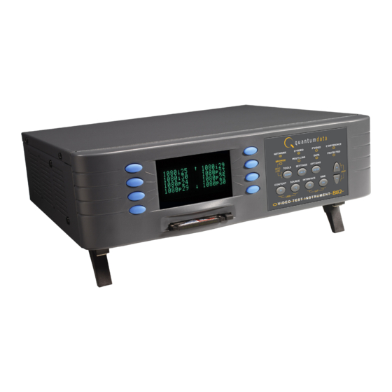
Introduction This User’s Guide describes the features, functions and operating procedures for the 881 and 882 Quantum Data video test instruments for testing analog and digital video display devices. The 881 provides features for testing video displays in production environments. - Page 15 • Self-calibrating–Analog video outputs are automatically adjusted against an internal precision reference. This assures video levels that are precise and reliable. Signal levels are auto-adjusted individually. • Probe–Trigger a scope or inspection camera using the probe signal. Position a pulse anywhere in the frame.
- Page 16 • Composite analog on S-video and BNC Connectors • For the 882E one of the two following analyzer options can be selected: Chapter 1 Getting Started...
-
Page 17: Video Interfaces
Video interfaces This section describes the 882’s video interfaces. The video interfaces on the 882EA HDMI are shown below (the 882E will not have the HDMI inputs but can have analog video outputs). Interface Description HDMI OUT 1 connector outputs full single link HDMI 1.3 video, as well as DVI and modern HDMI-compatible digital video signals. - Page 18 VGA interface The VGA interface, available on the model 882C generator, outputs analog video for testing analog video displays. The following table describes the VGA connector pinouts. Signal Signal Signal Analog Red Video Analog Red Video Ground No Connection Analog Green Video 7 Analog Green Video Ground 12 DDC/EDID Serial Data Analog Blue Video...
-
Page 19: Computer Interfaces
SERIAL connector provides RS-232C serial data communication interface for the 882. DEBUG connector is for Quantum Data use only. ETHERNET connector is used to connect the 882 with a TCP/IP network, for remote administration and control, and for sharing resources from a file server. - Page 20 GPIB interface The GPIB interface allows you to use the 882 as a programmable video signal source in a larger automated test system. The GPIB connector pinouts are listed in the following table. Signal Signal Signal Signal DIO1 NRFD DIO5 Shield DIO2 NDAC...
-
Page 21: Front Panel Interface
Front panel interface This section describes the front panel interface for operating the 882. The front panel keys are shown below. Item Display Soft Keys Status Indicators Recent Folder Tool ! Folder Setting - Disabled Rejected + Enabled Selected * Menu Selection Keys Status indicators Status indicators provide feedback about the operational status of the 882. -
Page 22: Menu Selection Keys
Menu selection keys You can access the 882’s menus using the menu selection keys depicted below. Set advanced parameters Set basic options for current items for current item Select tool Page up, increase value Page down, decrease value Select image Displays information about UUT Select user profile Select device type... - Page 23 Icon Meaning Indicates active item in list of mutually exclusive items. Item is active, but may be deactivated by pressing soft key. Item is not active, but may be activated by pressing soft key. Value may be increased by pressing Up (+) key, or decreased by pressing Down (-) key.
- Page 24 means that DSS is selected, the + sign next to SyncOnG means that this option is enabled, and the - signs next to Pedestal, SyncOnR, and SyncOnB mean that these options are disabled. If you press the soft key adjacent to SyncOnR, the - will change to a +, indicating the option is now enabled.
-
Page 25: 882 File System And Media
882 file system and media The 882 has a file system comprised of a System folder and a Library folder of resource files that can be stored on multiple media (storage devices or locations). The files in the file system are briefly described below. 882 file system The 882 generator file system is comprised of two main directories (folders): 1) System and 2) Library. -
Page 26: 882 Operational Modes
1. Apply power to the 882. The following display appears. If you are sure you want to boot from the current storage location you can let the system boot automatically. Quantum Data Windriver vxWorks System Boot Press any key for setup a. -
Page 27: Basic Mode
• To boot from the 882’s PC card, press the soft key adjacent to PCMCIA Boot. 4. Press the Options (Enter) key to save the configuration. 5. Either restart the 882 by cycling the power or press the Tools key to return to the boot menu. - Page 28 When in Browse mode, the selection keys shown below are active. To previous folder Go to root folder Open selected folder Page up Page down Jump to preset location The procedure below describes how to place the 882 in Browse mode: To place the 882 in Browse mode: Press and hold the Tools key.
- Page 29 2. Choose the folder you want to open by pressing the adjacent soft key. The contents of the folder appears on the 882’s display. If you need to return to the previous menu list press the back (settings) key. Fonts FormatLib Formats Images...
- Page 30 5. Select a format by pressing the adjacent soft key. The format path is now set to the selected folder on the selected medium. To set the 882’s path using the command line interface: 1. Establish a session with the 882 using either HyperTerminal over a serial connection or Telnet over an Ethernet LAN.
- Page 31 To program a function key as a folder shortcut: 1. Browse to the folder to which you want to create a shortcut. 2. Hold down a function key (F1, F2, F3, or F4) to assign the key to the folder. Switching from Browse mode to Basic mode To switch from Browse mode to Basic mode: Press and hold the Tools key.
-
Page 32: Web Interface
Web interface The 882 has a built-in Web server that enables you to interact with the 882 using a PC and an Ethernet connection. The Web interface includes the following functions: • Format Editor for creating formats and modifying and viewing format parameters. For more information about the Format Editor, see “Creating a new format using the Format Editor”... - Page 33 2. Choose the System item by pressing the adjacent soft key. The System menu appears on the 882’s display as shown below. Clock Clone* CalFactor Server Network About Serial GPib 3. Choose the Network item by pressing the adjacent soft key. The 882’s IP address appears on the 882’s display as shown below.
-
Page 34: Working With The Cmd (Command) Terminal
Note: You can add the page to your list of favorite pages in your Web browser to avoid retyping the IP address each time you want to access the page. 2. Click the Virtual Front Panel link. The Virtual Front Panel appears. 3. -
Page 35: Working With The 882 Ftp Browser
3. In the box at the top of the CMD Terminal window, enter a command, and then press Enter. The command appears in the lower pane. Working with the 882 FTP Browser If you create objects on a PC, such as images or formats, you can use the 882 FTP Browser to copy these objects to a 882. - Page 36 2. shows the files stored on the 882. The Host Files area shows the files stored on the PC. 3. In the Host Files area, locate and select the file or folder you want to copy. 4. In the Instrument Files area, locate the destination folder for the file as follows: a.
- Page 37 Copying files from a 882 to a PC To copy files from a 882 to a PC: 1. Access the 882’s FTP browser by choosing the FTP Browser menu item from the main web page. The 882 FTP Browser appears. The Instrument Files area shows the files stored on the 882.
- Page 38 5. Verify that the source file or folder and the destination folder are correct, and then click 6. The Copying Files dialog box appears showing the status of the operation. When the status is 100%, click Done. Copying files between the 882’s flash memory and PC card To copy files between media in a 882: 1.
-
Page 39: Copying Files Between 882S
4. Locate the file or folder you want to copy in the source window. 5. Locate and open the destination folder in the destination window. 6. Drag the file or folder from the Instrument Files area of the source window to the Instrument Files area of the destination window. - Page 40 2. Access the 882’s FTP browser by choosing the FTP Browser menu item from the main web page. The 882 FTP Browser appears. The Instrument Files area shows the files stored on the 882. The Host Files area shows the files stored on the PC. 3.
- Page 41 5. In the 882 FTP Browser window for the target 882, open the destination folder as follows: a. In the Look in box, click the down arrow and select the medium to which you want to copy the file or folder. Select tffs0 for the 882’s flash memory or card0 for the 882’s PC card.
-
Page 42: Command Line Interface
Command line interface Common test procedures can be accomplished using the 882’s physical controls on the front panel, Virtual Front Panel or through the command line interface. The 882 supports an ASCII command and query language that allows you to control the 882 interactively or through batch processing of command files. - Page 43 To configure the 882’s serial port through the front panel or Virtual Front Panel: 1. Press the Tools key. The Tools menu appears on the 882’s display as shown below. System Reports Sequence ImgShift Probe Analyzer 2. Choose the System item by pressing the adjacent soft key. The System menu appears on the 882’s display as shown below.
- Page 44 7. To change the number of data bits, do the following: a. Press the soft keys adjacent to the third row until CHAR appears. The current data bits setting is shown in the bottom row. Serial Port Set Params <- CHAR PRTY STOP...
-
Page 45: Working With The Network Interface
MODE? The 882 returns the current values: 9600,N,8,1,N,N 3. To change the settings, enter the following command: MODE baud parity data stop handshake protocol For example, to change the baud rate to 38400, enter the following command: MODE 38400 n 8 1 n n Note: In this example, after you press Enter, the baud rate of the session and baud rate of the 882 will no longer match. -
Page 46: Sending Commands Interactively
Sending commands interactively This section describes how to send commands through an interactive command line interface session. The 882 parses command lines one at a time. Command lines must be terminated with a carriage return (<cr>). The 882 immediately echoes each character as it is received and places it in a command line buffer. - Page 47 2. Establish a session with the 882 using a terminal emulator, such as HyperTerminal over a serial connection. 3. At the C:> prompt, transfer the text file to the 882. For example, to transfer a file using HyperTerminal, do the following: a.
-
Page 48: Working With User Profiles
Working with user profiles The 882 provides user profiles that enable you to quickly load pre-defined configurations. This can be done either through the front panel, virtual front panel or the command line. For example, you can create different profiles for each operator, production line, display type under test, and so on. - Page 49 1. Establish a session with the 882 using either HyperTerminal over a serial connection or Telnet over an Ethernet LAN. See “Establishing a terminal session with the 882” on page 30 or “Establishing a Telnet session with the 882” on page 33. 2.
- Page 50 Chapter 1 Getting Started...
-
Page 51: Chapter 2 Testing Video Displays
2 Testing Video Displays Topics in this chapter: • General video display testing procedures • Testing digital computer (IT) FPDs • Testing analog composite video SDTV (CE) CRTs • Testing analog component video SDTV (CE) CRTs • Testing digital component video HDTV (CE) FPDs •... -
Page 52: General Video Display Testing Procedures
General video display testing procedures This section provides an overview of basic steps performed to test your video display using your 882 or 881. Testing your video display involves four basic steps: 1. Connecting 882 to display under test. 2. Selecting interface type for display under test. -
Page 53: Selecting Interface Type
(SMPTE-259M) YCbCr and HD-SDI (SMPTE-292M-C) 1. Optional cable available from Quantum Data. Selecting interface type After making the physical connection, you are ready to select the interface type for your display under test. You can select the interface using either the front panel keys or the command line interface. - Page 54 To select an interface: 1. Press the Interface key to access the list of interfaces. A listing of signal interfaces appears on the 882’s display as shown below. CVBS S-VIDEO HDMI-D HDMI-H 2. Choose the interface by pressing the adjacent soft key. The interface is activated and the port outputs the currently selected image and format.
-
Page 55: Selecting Video Format
Selecting video format Once you have selected the interface type for the display under test, you need to select a video output format. A format defines a set of video, timing, and sync parameters for a specific device or standard. This section explains how to configure the 882 to output video formats that are supported by the display under test. - Page 56 To bypass hot plug detection: If the display under test has not implemented hot plug correctly, you will have to bypass hot plug detection in the 882 to enable video output. 1. Connect the 882 to the display you want to test. 2.
- Page 57 3. Press the Options key. The following information appears on the 882’s display. -EDID Formats +HP Bypass -Emulate 4. Choose the Emulate item by pressing the adjacent soft key. A + appears next to Emulate indicating enabled. Alternatively, to select the emulate mode through the command line interface, enter the command shown below: EMUG 1 // Enables emulate mode...
- Page 58 Upon selecting a format, you can modify the format options and settings if necessary. For instructions on this, see “Configuring format parameters” on page 177. Understanding the format library The 882 has several built-in formats to test a broad range of display types. These formats are grouped in the following categories: •...
-
Page 59: Selecting Image
Component high definition television formats Component high definition television formats, like the standard definition television formats, are named by their vertical resolution, scanning method, and frame rate. These formats are applicable in the case of RGB, YPbPr, and YCbCr. These initial characters indicating the resolution are followed by the scanning method. - Page 60 Once you have selected an image you can modify the image options if necessary. For instructions on this refer to “Viewing and modifying image options” on page 231. To select an image: 1. Identify the type of display (CRT or FPD) and the images that are used for testing this type of display (see the table below).
- Page 61 The table below provides a summary of display characteristics and the images used to evaluate them. For details on the images and display attributes, see Appendix B, “Image Reference.” Display type Display test Recommended images Analog CRT Geometry Static images (pin and barrel, linearity) Hatch (TVHatch, Hatch_16,...
- Page 62 Display type Display test Recommended images Digital flat panel Pixel anomalies Flat, Raster, Ramp_B, Ramp_G, and Ramp_R, (fixed pixel (stuck pixels, misc sampling) Focus_@6, Focus_@7, Focus_@8, display) Focus_@9, Text_9, Text_9T, Text_11, Text_12T, Text_16 Photometry (chrominance, Flat, Flat07, Flat13, Flat20, Flat27, Flat33, contrast, levels) Flat40, Flat47, Flat53, Flat60, Flat67, Flat73, Flat80, Flat87, Flat93, FlatGray, Flat_01,...
- Page 63 3. Toggle back and forth between the images using the adjacent soft key. To view multiple image versions in the Content list: 1. Select an image by pressing the Contents key and selecting an image with the adjacent soft key until a * appears next to image name. 2.
-
Page 64: Testing Analog Computer (It) Crts
3. Determine the formats to test (see “Setting Source list of formats” on page 43). 4. Determine additional formats to test based on the resolution of the display. The VESA formats are shown below: Standard Quantum Data format name DMT06xx SVGA DMT08xx DMT10xx SXGA... - Page 65 2. Choose the VGA item by pressing the adjacent soft key. The interface is activated and the port outputs the currently selected image and format. An asterisk is shown beside the selected interface. Alternatively, to select the interface through the command line interface, enter the following commands: XVSI // Selects the VGA interface...
- Page 66 unconnected channel. Also, look at the transitions between the bars; they should be sharp and distinct. Each bar also should be uniform in color and intensity across its entire width. • To test luminance, you can use the SMPTE133 (grayscale portion) image. To test gamma correction, you can use the SMPTE133 (checkerbox portion) image.
-
Page 67: Testing Digital Computer (It) Fpds
Testing digital computer (IT) FPDs This section describes how to test digital computer (IT) displays. You can test DVI on digital computer displays using the 882C up to single link through the HDMI connector. However you can test DVI digital computer displays up to full dual link on the 882D through the dual link DVI connector. - Page 68 FMTL DMT0660 FMTU 3. Press the Content key to access the list of images. 4. Choose a suitable image (for example, SMPTE133) by pressing the adjacent soft key. Alternatively, you can load the image with the following command: IMGL SMPTE133 IMGU 5.
- Page 69 • When testing for persistence with the animated images (for example, Cubes Persist), look for bleeding or trails in the wake of the moving object. Note: You can customize your 882 to run through a specified set of formats and images automatically or manually by creating test sequences.
-
Page 70: Testing Analog Composite Video Sdtv (Ce) Crts
Testing analog composite video SDTV (CE) CRTs This section describes how to test CRT composite televisions with analog composite video inputs. The display responses shown as examples in the procedures use the 882C. However you can also test analog composite with the 882D or 882E using the same interface, format and image selections. - Page 71 2. Choose a typical composite format (for example, NTSC) by pressing the adjacent soft key. Alternatively, you can load the format with the following command: FMTL NTSC FMTU 3. Press the Content key to access the list of images. 4. Choose a suitable image (for example, SmpteBar) by pressing the adjacent soft key. Alternatively, you can load the image with the following command: IMGL SmpteBar...
- Page 72 • When testing for centering, use the Outline and TVoutLin images. The detailed methods for verifying centering with the Outline images (Outline0, Outline1, Outline2, Outline3) are provided in Appendix B, “Image Reference.” • When testing for high voltage regulation with the Regulate image, observe the outline at the edges of the image.
-
Page 73: Testing Analog Component Video Sdtv (Ce) Crts
Testing analog component video SDTV (CE) CRTs This section describes how to test CRT televisions with standard definition component video inputs. The examples show the 882C. However there are notes that describe the differences related to the 882D. To set up the 882 to test an analog component video SDTV display: 1. - Page 74 2. Choose a standard component format (for example, 480i) by pressing the adjacent soft key. Alternatively, you can load the format with the following command: FMTL 480i FMTU 3. Press the Content key to access the list of images. 4. Choose a suitable image (for example, SMPTE133) by pressing the adjacent soft key. Alternatively, you can load the image with the following command: IMGL SMPTE133...
- Page 75 • When testing for centering use the TVOutline and Outline images. The detailed methods for verifying centering with the Outline images (Outline0, Outline1, Outline2, Outline3) are provided in Appendix B, “Image Reference.” • When testing for high voltage regulation with the Regulate image, observe the outline at the edges of the image.
-
Page 76: Testing Digital Component Video Hdtv (Ce) Fpds
Testing digital component video HDTV (CE) FPDs This section describes how to test digital DVI and HDMI component video for HDTV flat panel displays. The display responses shown as examples in the procedures use the 882C and 882E. However, you can also test dual-link digital component video with DVI using the 882D. - Page 77 Alternatively, to activate the interface through the command line interface, enter the following commands: XVSI // Selects the HDMI-D interface ALLU // Applies the interface setting to the 882 If you are using the 882D you can select either HDMI-D or DVI-D interface. The DVI-D option provide dual link, the HDMI-D offers signal link only.
- Page 78 methods for verifying these parameters on the SMPTE133 image are provided in Appendix B, “Image Reference.” • When testing for centering, use the Outline images. The detailed methods for verifying centering with the Outline images (Outline0, Outline1, Outline2, Outline3) are provided in Appendix B, “Image Reference.”...
- Page 79 To activate the HDMI-H interface on the output port: 1. Press the Interface key. A listing of signal interfaces appears on the 882’s display as shown below. CVBS S-VIDEO HDMI-D HDMI-H 2. Choose the HDMI-H item by pressing the adjacent soft key. The interface is activated and the port outputs the currently selected image and format.
- Page 80 • When testing photometry such as chrominence, use the ColorBar, SMPTE133, or SMPTEbar images. Look for missing bars which may indicate a dead or unconnected channel. Also, look at the transitions between the bars; they should be sharp and distinct. Each bar also should be uniform in color and intensity across its entire width.
-
Page 81: Using The Image Caching Feature
Using the Image Caching feature The Image Cache feature enables you to render images quickly. This feature is ideal for applications, such as production line testing, which require rapid image rendering. The Image Cache features renders a number of images in advance and stores them in memory for immediate recall. - Page 82 FMTL 720p60 // load format 720p60 FMTU 0 // use format without redrawing ICHL IMG4 // load cached SmpteBar for 720p60 ICHU // fast display of SmpteBar from cache ICHL IMG5 // load cached Ramp_B for 720p60 ICHU // fast display of Ramp_B FMTL DMT0660 // load format DMT0660 FMTU 0...
-
Page 83: Using The Auxtest Image
Using the AuxTest image This section describes the AuxTest composite test image used in production. This image tests an HDMI sink for CEC, EDID and HDCP at the same time. The CEC test is a simple ping test. The HDCP test is an authentication test. The EDID test is a checksum test. Use the procedure below to test a sink for CEC, EDID and HDCP. - Page 84 device. The section in the center shows the step by step results (11 steps) of the first phase of the HDCP authentication. Below that is the ongoing test results of the third phase of authentication, i.e. exchanging the Ri values. Chapter 2 Testing Video Displays...
-
Page 85: Using The Imageshift Utility
Using the ImageShift utility This section describes the ImageShift utility and how to use it. The ImageShift utility allows you to set in motion any of the built-in or bitmap static images stored in the 882. Image shifting can be controlled at both the pixel level in horizontal and vertical directions, and on a per frame basis. - Page 86 5. Choose Images, and then select the image you want to use. The image appears and begins shifting in accordance with default settings for both speed and method of shifting (either repeat or reversed). The following settings appear on the 882’s display as shown below. >Line Reversed<...
- Page 87 by the coordinates to move the cursor left or right until it appears on the digit in the X coordinate. Adjust the value of the setting up or down by pressing the + or - keys. b. To specify the Y Start Point, position the blinking cursor on the digits of the Y coordinate you wish to change.
-
Page 88: Using The Imageshift Utility Through The Command Line Interface
• To return to the previous screen without saving the changes, choose the Back item. Using the ImageShift utility through the command line interface The procedures for configuring and running the ImageShift utility from the command line interface are given below. To run the ImageShift utility from the command line interface, you must utilize an imageshift file. - Page 89 ISHL Newshift //Loads the values from the imageshift file named //Newshift ISHG //Initiates (gates on) the imageshift function ISHU //Applies the values to the hardware 5. Apply the imageshift file to the hardware using the ISHU command. For example: ISHU //applies the imageshift file to the hardware To stop the ImageShift utility through the command line interface: 1.
-
Page 90: Adjust Frequency Function
Adjust Frequency Function This section describes the adjust frequency control (AFC) function. The AFC function provides you with the ability to increase or decrease the horizontal frequency (HRAT parameter) of the active video format in increments of 2%. Use the following procedures to increase or decrease the frequency of the active format. To utilize the AFC function: 1. -
Page 91: Keypad Utility
Keypad Utility This section describes the Keypad utility and how to use it. The keypad provides you with a quick and convenient way of changing between formats and images. The interface from the Keypad to the 882 is through the serial interface. Once connected you can change between formats and image with a single key stroke. - Page 92 To monitor the status of the keypad: 1. Press the Tools key. The Tools menu appears on the 882’s display. When the keypad has been enabled there is an additional item in the Tools menu. This is indicated by an arrow key. If you scroll down using the - key the following menu appears: Sequence ImgShift...
- Page 93 To operate the keypad 1. Use the figure below to operate the keypad. The keypad has two basic modes: 1) Normal which enables you to change the formats, images and colorimetry and 2) Sequence mode which enables you to control a running test sequence. Normal mode key functions Sequence mode key functions Switch to Sequence Mode...
- Page 94 Chapter 2 Testing Video Displays...
-
Page 95: Chapter 3 Administrative Tasks
3 Administrative Tasks Topics in this chapter: • Overview • Calibrating the generator • Auto Upgrade • Upgrading the generator locally • Reconfiguring and booting a stalled generator • Cloning generators • Resetting a generator • Viewing generator configuration information 882 Video Test Instrument User Guide (Rev A.35) -
Page 96: Overview
Overview This section describes how to accomplish administrative tasks, including calibrating the generator, upgrading a generator, cloning a generator and maintaining the generator’s file system. Chapter 3 Administrative Tasks... -
Page 97: Calibrating The Generator
Calibrating the generator The 882 generator can calibrate itself. Once calibrated, the generator does not require periodic calibration. There are no physical controls to adjust. All calibration is electronic. Calibration factors are saved in non-volatile memory. Calibrating signal level The calibration accuracy of the generator for analog video voltage swing is specified to be ±14 mV (or ±2% for a nominal 700 mV signal). -
Page 98: Calibrating Frequency
4. Choose the CalFactor item by pressing the adjacent soft key. The following items appear on the generator’s display: Edit-Factors Self-Calibrate 5. Choose the Self-Calibrate item by pressing the adjacent soft key. During calibration, calibration factors and other information appear on the generator’s display. - Page 99 2. Measure the TTL horizontal sync frequency with the frequency counter. 3. Divide the frequency that you expect by the frequency that you measure on the frequency counter. For example, if you measure 99.9955782499875 kHz, when you expect 100.000000000KHz, then divide 100.000000000 kHz by 99.9950002499875 kHz;...
-
Page 100: Auto Upgrade
Quantum Data periodically makes available new firmware releases for the 880 series generators. The Auto Update utility automates the process of upgrading firmware. It guides the user through the upgrade process, checking the Quantum Data website for the latest version and installing all files in the correct location on the generator. - Page 101 DHCP server on the network. The PC has to be connected to the Internet. Refer to the 880 Series User Guide, Chapter 4, “Networking 882s.” for full information on configuring a generator for network use. Refer to the diagrams below. Downloading and installing the Auto Update utility: The Auto Update utility is java-based, and requires the Java Virtual Machine (Java runtime) to be installed on the computer.
- Page 102 Running the Auto Update utility: Network Upgrade 1. Run the utility by double-clicking on AutoUpdate.jar. You will be presented with the following screen: Chapter 3 Administrative Tasks...
- Page 103 2. Select Network Upgrade, then Next. The Network Upgrade screen will appear: 3. Make sure you have network access to the generator, then select Next. Next you will have the opportunity to back up the files in the generator. If you have any custom images, formats, reports, or other files stored on the /tffs0 flash drive within the generator, they will be lost unless you choose to back up the files.
- Page 104 4. Optionally browse to a new backup directory, then click Next to begin the backup. If you don’t want to back up any files from the generator, click on Skip Backup. 5. Next, enter the IP address for the generator: Chapter 3 Administrative Tasks...
- Page 105 6. Click Next to continue. 7. If you see this screen, click Continue With Upgrade: 882 Video Test Instrument User Guide (Rev A.35)
- Page 106 8. Next you must confirm that you are connected to the correct generator: Click Yes to continue. Next the utility will connect to the Quantum Data website to download the current firmware version for this generator, then display the version number and wait for your confirmation.
-
Page 107: Auto Upgrade - Pcmcia/Compact Flash Method
10. Now you must power cycle the generator to boot from the new firmware. Auto upgrade - PCMCIA/Compact Flash Method The second method of upgrading the generator using the auto upgrade feature is the PCMCIA/Compact Flash upgrade. This method is used when you connect the generator to the network and you cannot connect the PC to the generator but requires that you have a PC that is connected to the network (Internet). - Page 108 upgrade files from the computer to the generator. The Auto Upgrade utility prompts the user when the PCMCIA/Compact Flash card must be moved between the computer and the generator. Running the Auto Update utility: PCMCIA Upgrade 1. Run the utility by double-clicking on AutoUpdate.jar. You will be presented with the following screen: Chapter 3 Administrative Tasks...
- Page 109 882 Video Test Instrument User Guide (Rev A.35)
- Page 110 2. Select PCMCIA Upgrade; then click Next. Prepare the PCMCIA/Compact Flash card per the following screen: 3. Click Next, then enter generator information (genstats) on the following screen. The button How To Get Genstats Manually will show you the method for reading genstats on an attached display.
- Page 111 5. When this information is correct, click on Next. 6. The utility will download the new firmware files from the Quantum Data website, and report the version number of the release: 7. Click on Yes, and the utility will extract the individual files from the downloaded release archive.
- Page 112 Chapter 3 Administrative Tasks...
- Page 113 8. Next you will be prompted to hit the Clone Capture button (Tools -> System -> Clone -> Capture.) This will cause the generator to back up the internal files to the PCMCIA/Compact Flash card. When this process is complete, insert the card into the computer and click on Next.
- Page 114 10. When the drive address is selected, click Next, and the backup files will be copied from the card onto the PC. When the backup is completed, the new release files will be Chapter 3 Administrative Tasks...
- Page 115 copied onto the card. Then you will be prompted to insert the card back into the generator. 11. Click Next, and you will see the following screen instructing you to initiate the clone restore process by pressing Tools -> System -> Clone -> Restore. 882 Video Test Instrument User Guide (Rev A.35)
- Page 116 12. After the clone restore is complete, you will again see the menu on the generator’s screen. Then click on Next. Chapter 3 Administrative Tasks...
- Page 117 882 Video Test Instrument User Guide (Rev A.35)
- Page 118 13. Power cycle the generator, and it will boot the upgraded firmware. Chapter 3 Administrative Tasks...
-
Page 119: Upgrading The Generator Locally
Follow this procedure to upgrade a generator using the PC card. To upgrade a generator using the PC card: 1. Download the new release zip file from the Quantum Data download page (http://www.quantumdata.com/downloads/index.asp) and extract into a folder on your 2. - Page 120 3. If your PC does not have access to a PCMCIA slot or device, use the following procedure. You can skip this step if you performed Step 2 above. a. Access the generator’s main web page. For details on this, see “To connect directly to the generator:”...
-
Page 121: Manually Upgrading The Generator Without Using Pc Card
In the Host Files area, locate and select the new release files (System and Library directories) to transfer to the PC card. g. In the Host Files area, click Download. The Transfer Files dialog box appears. h. Verify that the source file or folder and the destination folder are correct, and then click OK. - Page 122 1. Download the new release zip file from the Quantum Data download page (http://www.quantumdata.com/downloads/index.asp) and extract into a folder on your 2. Access the generator’s main web page. For details on this, see “To connect directly to generator:” on page 115.
-
Page 123: Connecting Generator Directly To A Pc
7. In the Instrument Files area, select all of the folders (or only the specific files in the lower pane that you want to backup). 8. Click Upload. A Transfer Files dialog box appears. 9. Verify that the source file or folder and the destination folder are correct, and then click OK. - Page 124 To set the generator’s IP address: 1. Press the Tools key. The Tools menu appears on the generator’s display as shown below. System Reports Sequence ImgShift Probe Analyzer 2. Choose the System item by pressing the adjacent soft key. The System menu appears on the generator’s display as shown below.
- Page 125 6. To save the changes, press the Enter (Options) key. The following choices appear on the generator’s display: Apply Settings? Back To save the changes, choose the Yes item by pressing the adjacent soft key. To exit without saving the changes, choose the No item. To return to the previous screen without saving the changes, choose the Back item.
- Page 126 Note: If you have more than one Ethernet card make sure you configure the select the correct one. Chapter 3 Administrative Tasks...
- Page 127 4. In the Internet Protocol (TCP/IP) Properties dialog box, select Use the following IP address and type the IP address in the box. Note: IP addresses consist of a network component and a host component. The network component is represented by the first 3, 6, or 9 digits of the address, depending on the network class.
- Page 128 7. Open a Web browser (such as Internet Explorer) and type the generator’s IP address in the address entry field. For example, enter the following: http://206.135.215.189/ The generator web page appears in the browser. Chapter 3 Administrative Tasks...
-
Page 129: Reconfiguring And Booting A Stalled Generator
Follow the procedures below to boot the generator in these instances. To boot a generator that is in a stalled state: 1. Apply power to the generator. The following display appears. Quantum Data Windriver vxWorks System Boot Press any key for setup To boot from an alternative device, press any key within three seconds. - Page 130 6. Scroll down to the allow viewing and selection of the BootNow item as shown below. !FileName !Other !InetAddr !TrgtName !HostAddr BootNow !User 7. Select BootNow by pressing the adjacent item selection key. 8. The following display appears: Press UP arrow to Boot Now 9.
- Page 131 Press UP arrow to Boot Now 10. Press the + key to boot the generator. The following display appears and the generator boots up. Quantum Data Windriver vxWorks System Boot Press any key for setup 11. Press the Tools key. The Tools menu appears on the generator’s display as shown below.
- Page 132 18. Repeat the procedure. To boot a stalled generator from a different host: 1. Power down the generator, hold down the Tools key and then re-apply power to the generator. The following screen appears on the generator’s display: !BootDev !Passwd !HostName !Flags !FileName...
- Page 133 To change the IP address of the generator: 1. From the Boot Menu select !InetAddr. !BootDev !Passwd !HostName !Flags !FileName !Other !InetAddr !TrgtName 2. Choose the !InetAddr by pressing the adjacent item selection key. The generator’s IP address and subnet mask appear on the generator’s display as shown below. Network Connection Set TCP/IP IP Address...
-
Page 134: Cloning Generators
Cloning generators You can clone generators using either the generator’s PC card or the Generator FTP Browser over an Ethernet connection. To clone a generator, the firmware revision of the source and target generators must match. Cloning a generator using the PC card Follow this procedure to clone a generator using the PC card. -
Page 135: Cloning A Generator Using The Generator Ftp Browser
8. On the target generator, press the Tools key. The Tools menu appears on the generator’s display as shown below. System Reports Sequence ImgShift Probe Analyzer 9. Choose the System item by pressing the adjacent soft key. The System menu appears on the generator’s display as shown below. - Page 136 2. Access the source generator’s Generator FTP Browser. See “Working with the 882 Browser” on page 23. 3. Copy all of the files in the source generator’s flash memory to the PC as follows: a. In the Instrument Files area of the Generator FTP Browser window, click the down arrow by the Look in box and select tffs0 (FlashMem).
- Page 137 5. Disconnect the source generator from the Ethernet cable and connect the target generator. Note: If both generators on the Ethernet/IP network you do not have to disconnect the generator. 6. Access the target generator’s FTP Browser. 7. Delete the current system and library resource folders from the target generator’s flash memory as follows: a.
-
Page 138: Resetting A Generator
Resetting a generator You can reset a generator to a known good condition. Note: Resetting does not restore the generator to factory default condition. Thus, it should not be used to restore proper operation of the generator. Follow this procedure to reset a generator. To reset the generator using the command line interface: 1. -
Page 139: Viewing Generator Configuration Information
Viewing generator configuration information You can view information about a generator’s configuration, including the firmware and gateware revisions, installed options, board serial numbers, and so on. The procedure for accessing this information depends on the type of information you want. •... - Page 140 5. To view the video board information, pressing the soft key adjacent to the arrow by Main Board. The video board build date appears as shown below. Press the soft key adjacent to the arrow by Build Date to see other information about the video board. About <- Video Board...
- Page 141 4. Enter the following command to view the generator firmware version (runtime and boot code versions): VERF? 20.0882002,01.04.11 5. Enter the following command to view the generator gateware information for each programmable device: VERG? 253C,36,1272005:253F,73,8292005:253A,5,4252005 The information provided for each gateware is the Product Code, Revision Code and Date Code.
- Page 142 5. Open a Web browser (such as Internet Explorer) and type the generator’s IP address in the address entry field. For example, enter the following: http://206.135.215.189/ The generator home page appears in the browser. Note: You can add the page to your list of favorite pages in your Web browser to avoid retyping the IP address each time you want to access the page.
- Page 143 6. Choose the Generated Reports item. The Generator the provides a list of reports currently available as shown below. 882 Video Test Instrument User Guide (Rev A.35)
- Page 144 7. Select the GenStats report. The GenStats report then appears in the browser window as shown below. You can then save the report as an web page file for distribution. Chapter 3 Administrative Tasks...
-
Page 145: Chapter 4 Networking 882S
4 Networking 882s Topics in this chapter: • Overview • Configuring a file server • Establishing a network environment • Network operations • Controlling a 882 remotely • Upgrading 882s over a network • Cloning 882s using the 882 FTP Browser 882 Video Test Instrument User Guide (Rev A.35) -
Page 146: Overview
Overview This chapter describes how to use the 882 in a networked environment. Quantum 882 generators can operate and be administered over an Ethernet LAN connection. By networking multiple 882s together, you can centralize control in production environments. When networking 882s, a file server containing a set of system and resource files is installed on the network. -
Page 147: Configuring A File Server
Configuring a file server This section describes how to set up a file server. The file server is a PC used to host the 882 system and resource files to be shared by networked 882s. To configure the file server, you must install FTP server software on it, create an FTP directory (site), and copy the 882 system and resource files into the FTP directory. - Page 148 To set up the FTP server: 1. Install the FTP server software on the file server PC and create the FTP site directory. You can use Microsoft Internet Information Services shown below. 2. Configure the FTP site properties. a. On the Home Directory tab, enter the name of the Local Path (your default directory for the FTP server).
- Page 149 uses C:\Inetpub\ftproot as the local path as shown below. You can use this path or click Browse to select a different path. b. On the Home Directory tab, specify read/write access. c. On the Security Accounts tab, select Allow only anonymous connections, and then click OK.
-
Page 150: Copying Resource Files To The Ftp Site On The File Server
After installing the FTP server, you can download the 882 system and resource files from the Quantum Data Web site and copy them to the FTP site on the file server. To copy 882 system and resource files to the file server: 1. - Page 151 4. Move the vxWorks file out of the System folder and into the ftproot folder. 882 Video Test Instrument User Guide (Rev A.35)
-
Page 152: Establishing A Network Environment
Establishing a network environment To create a network environment for your 882s, you must physically connect the 882s to the network, and then configure their IP addresses and the IP address of the file server. Procedures for these tasks are described in this section. Connecting 882s to the network In a typical networked environment, you will connect the 882s to the corporate, IP-based Ethernet LAN. -
Page 153: Setting The 882'S Ip Address
When the network connection on the 882 is active, the Network LED lights on the front panel. Setting the 882’s IP address You can either set the IP address of the 882 manually with an address you select or automatically by using the built in DHCP support. The default state of the 882 is that DHCP is off. - Page 154 4. Press the Settings key. The Network Connection screen appears on the 882’s display as shown below. Network Connection Set TCP/IP IP Address 206.135.215.168 If the IP Address configuration option is not visible, press the soft key adjacent to the arrow symbol by SubnetMask until IP Address appears.
- Page 155 To enable DHCP for auto IP address configuration of the 882: 1. Press the Tools key. The Tools menu appears on the 882’s display as shown below. System Reports Sequence ImgShift Probe Analyzer 2. Choose the System item by pressing the adjacent soft key. The System menu appears on the 882’s display as shown below.
- Page 156 6. To save the changes, press the Enter (Options) key. The following choices appear on the 882’s display: Apply Settings? Back To save the changes, choose the Yes item by pressing the adjacent soft key. To exit without saving the changes, choose the No item. To return to the Network Connection screen without saving the changes, choose the Back item.
- Page 157 4. Press the Settings key. The Network Host screen appears on the 882’s display as shown below. Network Host Set Boot Host Host Address 206.135.215.218 If the Host Address configuration option is not visible, press the soft key adjacent to the arrow symbol by Host Name until Host Address appears.
-
Page 158: Network Operations
Network operations This section provides common networking tasks, such as booting 882s from the file server, accessing files stored on the file server, transfering files from the file server to the 882, and controlling the 882 remotely. Booting a 882 from the file server A 882 can be set up to boot from an operating system (vxWorks) file stored on the file server. -
Page 159: Sharing Objects On A File Server
Sharing objects on a file server The 882 can be set up to access shared format, image, and sequence files stored on a file server. To do this, you must set the 882’s path to point to the corresponding folders on the file server. - Page 160 4. Press the soft key adjacent to the folder you want to use. For example, to use the Formats folder, press the soft key adjacent to Formats. The contents of the selected folder appears on the 882’s display. 5. Choose an item by pressing the adjacent soft key. The path is now set to the selected folder on the file server.
-
Page 161: Controlling A 882 Remotely
Controlling a 882 remotely In addition to controlling the 882 using the front panel keys, you can also control the 882 from a remote PC either through the Virtual Front Panel Web-based interface or the command line interface. Using the Virtual Front Panel to operate a 882 remotely The 882 generator has a built-in Web server that provides a graphical interface called the Virtual Front Panel to control the 882. -
Page 162: Upgrading 882S Over A Network
To begin an upgrade, you must either have a CD-ROM containing the new files, or download the files from the Quantum Data Web site. You will copy the new files to your file server PC which must be connected to the LAN through the Ethernet cable. -
Page 163: Copying Files To The Pc File Server
FTP folder on the file server, and then copy the new, updated files to the FTP folder. Before you begin, you must either have a CD-ROM containing the new system, gateware, and library files, or download the files from the Quantum Data Web site. To copy the new files to the file server: 1. -
Page 164: Removing Current Files From The 882S
3. Copy the contents of the 882 folder to the FTP site folder. The resulting folder structure is shown below. Removing current files from the 882s Prior to upgrading the 882s, you must remove the existing system and firmware file, gateware, and resource files from the flash memory of each 882. -
Page 165: Cloning 882S Using The 882 Ftp Browser
Cloning 882s using the 882 FTP Browser You can clone 882s either through the front panel or through the 882 FTP Browser on the Virtual Front Panel Web page. Procedures for cloning 882s through the front panel are provided in “Cloning generators”... - Page 166 3. In the 882 FTP Browser window for the target 882, delete all of the files in the target 882’s flash memory as follows: a. In the Instrument Files area, click the down arrow by the Look in box and select tffs0.
-
Page 167: Chapter 5 Using Gpib Interface
5 Using GPIB Interface Topics in this chapter: • Overview • Setting the GPIB port address • Queries and commands • Status queries and control 882 Video Test Instrument User Guide (Rev A.35) -
Page 168: Overview
Overview You can operate and program the generator from an external computer or terminal using the optional IEEE-488 (GPIB) interface. The GPIB interface enables the generator to be used as a programmable video signal source for integration into automated test systems that use IEEE-488 or GPIB communications between instruments. -
Page 169: Setting The Gpib Port Address
Setting the GPIB port address The default GPIB address is 15. You can specify a different address as described in the procedure below. To set the address of the GPIB port using the front panel: 1. Press the Tools key. The Tools menu appears on the generator’s display as shown below. - Page 170 3. Enter the following command to set the address: address GPIB When the address is changed with the GPIB command, the change takes place as soon at the command is issued. Chapter 5 Using GPIB Interface...
-
Page 171: Queries And Commands
Queries and commands The GPIB interface is an ASCII command line interface like the RS-232 command line interface. The communications protocol is per IEEE-488.2 specification. Queries and commands consist of four ASCII upper/lower case characters. Commands do not require a response from the generator, while queries cause the generator to respond with the required data. -
Page 172: Queries
For example, the following number can be represented in three ways: • Integer (42) • Floating point (42.00) • Scaled floating point (4.200E+01) Queries Queries are comprised of a header followed immediately by a question mark (?). If there are any characters between the query header and the question mark character (including whitespace), a command error will result. -
Page 173: Sending Commands And Queries
Sending commands and queries The generator parses command lines one at a time. Command lines must be terminated with a carriage return (<cr>).The generator immediately echoes each character as it is received and places it in a command line buffer. This buffer currently has room for a total of 256 characters. - Page 174 to wait for all preceding commands to be completed before the commands that follow *WAI are processed. For example, sending the following command line causes a red rectangle to be drawn and then overwritten by the ColorBar image. IMGL COLORBAR; IMGU; IMGE; RECT RED 200 200 0 0 GRAYPAT100 Note that the IMGU command merely requests that the current image be rendered...
-
Page 175: Status Queries And Control
Status queries and control To create applications that control the generator using the GPIB port, it is sometimes necessary to query the status of the generator and set or reset the status bits and bytes. There are two sets of status registers: 1) the Event Status Register and Event Status Enable Register and 2) the Status Byte Register and Service Request Enable Register. - Page 176 The following figure illustrates IEEE-488 status reporting. Standard Event Status Register & & & & & & & & Queue Not-Empty Standard Event Status Enable Register Output Queue Service Status Byte Register 6 ESB MA V Request Generation & & &...
-
Page 177: Bus Commands
Event Status bit Definition Operation complete. Indicates that all operations have been completed. Request control. Indicates that a device is requesting control. The generator will never request control, so this bit will always be 0. Query error. Indicates that a query request was made while the generator was in deadlock. - Page 178 In the remote with lockout state (RWLS), the generator is under complete remote control and front panel controls are disabled. The generator enters the RWLS state when the controller issues the local lockout (LLO) message to the generator. Front panel access is re-enabled when the controller issues the go to local (GTL) message to the generator.
-
Page 179: Chapter 6 Working With Formats
6 Working with Formats Topics in this chapter: • Overview • Format library • Viewing the source list of formats • Configuring format parameters • Format Editor Overview • Creating a new format using the Format Editor • Creating custom formats using the command line interface •... -
Page 180: Overview
Overview The generator contains a library of standard formats. You can create your own formats, however, either by using the Format Editor or by entering format commands through the command line interface. You can also create format catalogs which allow you to control the formats that appear on the generator’s display when you press the Source key. -
Page 181: Format Library
Format library The generator has a built-in library of formats which are stored as XML files in any of the generator’s media. This section describes three sets of naming conventions for identifying formats: 1) Composite television formats, 2) Component television formats, and 3) Computer display formats. -
Page 182: Component Television Format Names
Common composite TV formats with sub-carriers and their respective standards: • NTSC - ITU-R BT.470-6 • NTSC# - SMPTE 170M • NTSC#KA - SMPTE 170M • PAL - ITU-R BT.470-6 • PAL# - ITU-R BT.470-6 • PAL#KA - ITU-R BT.470-6 Component television format names Component television formats are named by their vertical resolution and scanning method. -
Page 183: Computer Display Format Names
Frame rate Frame rate is optional. If no frame rate is given, then the frame rates are assumed. • 24 = 24 Hz • 60 = 60 Hz Common component TV formats • 480pLH Component SDTV signal containing letterboxed 16x9 high-definition content •... -
Page 184: Aperture Designators
Frame rate examples (half the field rate with interlace scanning) • 48 for 48 Hz • 60 for 60 Hz • 75 for 75 Hz Aperture (used only when the aperture is not A) “Aperture designators” on page 174. Common computer display formats •... - Page 185 • S = Scope (under-sample content horizontally) • W = Widescreen (over-sample content horizontally) • J = Justify (non- linear horizontal expand – more near edges) • K = Keep safe (shrink to avoid cropping – provide safe title) • P = Pan &...
-
Page 186: Viewing The Source List Of Formats
Viewing the source list of formats You can view the list of formats available in the generator using the front panel or the command line interface. Use the following procedures to view the Source (format) list. Note: The Source list of formats that appears on the generator’s display is determined by the format path. -
Page 187: Configuring Format Parameters
Configuring format parameters Each standard and custom format is defined by a set of parameters. These parameters are categorized in the generator as either Options or Settings. You can view and modify the parameters of a format in the following ways: •... - Page 188 4. To see more options, press the Options key again. The following appears on the generator’s display as shown below. *FullRange ShootRange LimitedRange 5. To see more options, press the Options key again. The following appears on the generator’s display as shown below. SyncOnR+ *ACS SyncOnG+...
- Page 189 4. To save the changes, press the Enter (Options) key. The following choices appear on the generator’s display: Apply Settings? Back To save the changes, choose the Yes item by pressing the adjacent soft key. To exit without saving the changes, choose the No item. To return to the parameters screen without saving the changes, choose the Back item.
- Page 190 Parameter Class Parameter Type Parameters Encoding DAST, NDAS, NDAC, NBPA Components DAXG, DAXA SDMG, DADG, DALS Channels DACA, DACG Sampling Rate ARAT, BRAT Audio Timing To view a format’s parameters on a display connected to the generator: 1. Press the Source key and choose a format by pressing the adjacent soft key. 2.
-
Page 191: Viewing And Modifying Format Parameters Via The Command Line
2. Enable and view image versions as follows: a. Press the Options key. The following menu appears on the generator’s display: -More Red+ -NoGamma Green+ -Noise Blue+ b. Choose the More item by pressing the adjacent soft key until a + and Rendition appears next to the item. -
Page 192: Viewing And Modifying Format Parameters By Editing Xml Files
3. To view options, enter the commands for the format options you want to view. For example, to view the sync configuration, enter the following command: ASSG? The generator responds with the information as shown below: 0, 1, 0 // Indicates no sync on red, sync on green, no sync on blue 4. - Page 193 To view and modify a format’s parameter values in the format’s XML file: 1. Using the Generator FTP Browser, copy the format’s XML file from the generator to a PC. See “Copying files from a 882 to a PC” on page 25 for instructions. 2.
-
Page 194: Format Editor Overview
Format Editor Overview The Format Editor provides a graphical user interface for modifying existing formats, creating custom formats and viewing format parameters. The Format Editor is part of the generator’s Web server and is accessed over an Ethernet LAN connection using a Web browser, such as Microsoft Internet Explorer. -
Page 195: Format Editor - Top Level Menus
Clicking on the activation button in the center of the figure below will dock the window into the main Format Editor window such that it will occupy the entire window opening of the Format Editor. Clicking on the right most activation button in the figure below will close the window. Format Editor - Top Level Menus The top level menus of the Format Editor are shown below. - Page 196 Menu Description New Source Menu Opens up the Source Menu (equivalent to clicking on the New Source Menu activation button). Open Enables you to browse to and open an xml format file on your PC. This is equivalent to clicking on the Open activation button.
-
Page 197: Format Editor - Menu Buttons
Format Editor - Menu Buttons The activation buttons of the Format Editor are shown in the window below. The following table describes the Format Editor menu buttons. Button Description Clicking on this button enables you to establish a connection between the Connect Format Editor and the 882E. -
Page 198: Format Editor - New Format
Format Editor - New Format This subsection defines the tabs and status panels available with the New Format screen shown below. The table below describes the tabs available for the New Format window. Description / Function Selecting the Timing tab opens up an application screen that enables you to Timing define the timing parameters for a custom format or modify the timing parameters of an existing format. - Page 199 Description / Function Selecting the General tab opens up an application screen that enables you Digital Audio to define the digital audio parameters for a custom format or modify these parameters of an existing format. (See “New Format - Digital Audio Tab”...
- Page 200 New Format - Timing Tab The Timing window of the Format Editor Timing is shown below. This window is activated by pressing the Timing tab. The main panel of the Timing tab is shown below. Chapter 6 Working with Formats...
- Page 201 The table that follows describes each of the fields in the main panel of the Timing tab. Entity Field Description / Function Sets the pixel rate in pixels (Machine) or microseconds Pixel Rate (Time) of the format. Horizontal The horizontal line rate of the format. The HRAT is the Rate fundamental frequency in the 882.
- Page 202 Entity Field Description / Function Indicates that the values in this field are settable in the current configuration. Red Field Indicates that the fields are in the read only mode. These fields will show a change in value when the value in a field affecting these fields is modified.
- Page 203 New Format - Timing Tab (Right Side Panel) The right side panel of the Timing tab in the Format Editor is shown below. The table that follows describes each of the fields in the panel. New Format - Timing (Right Side Panel) Entity Parameter Description / Function...
- Page 204 Entity Parameter Description / Function PreEmphasis Enables and disables adding pre-emphasis to the Open LVDI digital outputs on generators that support LVDI outputs. DC Balance Not used Flat Front Porch Determines if composite sync will have all equalization pulses removed in the vertical sync front porch (delay) period as required by certain military HOBO and Maverik video formats.
- Page 205 New Format - General Tab (Top Left Panel) The top left panel of the General tab in the Format Editor is shown below. The table that follows describes each of the fields in the top left panel of the General tab. Field / Entity Type Description / Function...
- Page 206 New Format - General Tab (Center Panel) The center panel of the General tab in the Format Editor is shown below. Chapter 6 Working with Formats...
- Page 207 The table below describes the pull-down menus in the center panel of the General tab. Field / Entity Description / Function Sets the colorimetry of the format. The parameter is AVST or DVST. The Color Encoding following are the selections: •...
- Page 208 Field / Entity Description / Function Sets the analog composite sync type of the format. The parameter is ASCT. ACS Type The following are the selections: • None • American ORed • American Single Serrated • American Double Serrated (ref SMPTE 170M NTSC) •...
- Page 209 Field / Entity Description / Function Sets the digital composite sync type of the format. The parameter is DSST. DSS Type The following are the selections: • None • American Separate • European Separate • American Separate HDTV • European Separate HDTV •...
- Page 210 Field / Entity Entity Type Description / Function Check box Enables or disables Gamma. Used with the entry field Gamma below. Parameter: GAMC. Entry field Enables you to set the Gamma once the Gamma check box above is enabled (checked). The allowable ranges of values is 0.1 to 10.0.
- Page 211 The table below describes the gating functions of the right-side panel of the General tab. Field / Entity Entity Type Description / Function Select buttons Enables you to put the analog composite sync on one of Analog Sync Gate the components when analog composite sync is selected as the sync type using the SSST command.
- Page 212 New Format - Digital Video Tab The Format Editor Digital Video tab is shown below. The table that follows describes each of the fields in the Digital Video tab. Entity / Field Type Description / Function Entry field Range Entry field Specifies the number of clocks per pixel (double Clocks per Pixel clocking factor for whole line.
- Page 213 Entity / Field Type Description / Function Entry field The digital video code corresponding to the AVI Video EIA/CEA-861 standard. Parameter: DVIC. Identification Code Radio button Number of Links 1 Sets the number of links to 1 by the DVI output. 2 Sets the number of links to 2 for the DVI output Parameter: NLNK Pull-down select...
- Page 214 New Format - Digital Audio Tab The Format Editor Digital Audio tab is shown below. The table that follows describes each of the fields in the tab. Chapter 6 Working with Formats...
- Page 215 The table below describes each of the fields in the Digital Audio tab. Field Type Description / Function Pull-down select Sets the digital audio signal interface. The valid values Signal Interface are: • None - Use HDMI. • SPDIF. • AES3 (not used). •...
- Page 216 Field Type Description / Function Pull-down select Sets the digital audio sampling rate. The valid values Bits per Sample are: • 16 • 20 • 24 Parameter is: NBPA. Entry field Sets the digital audio content gate. The valid values are: Contents Gated 0 through 4095.
- Page 217 New Format - AFD Tab The Format Editor AFD tab is shown below. The table that follows describes each of the fields in the tab. The table that follows describes each of the text entry fields in the AFD tab. Heading Field Description / Function...
- Page 218 Heading Field Description / Function Enables you to set the mapping type for mapping Extended From CXAR-shaped image content into the extended Content Apert. EXAR-shaped aperture. Parameter: EXCX Enables you to set the mapping type for mapping Signal from EXAR-shaped image content into the SXAR-shaped Extended Apert.
-
Page 219: Format Editor - New Report
Format Editor - New Report This subsection defines the New Report screen. The contents of the New Report tab is shown below. 882 Video Test Instrument User Guide (Rev A.35) - Page 220 The table below describes the top selection panels for the New Report activation button Entity Type Description / Function Status text field Shows the current connection status. Instrument (Connection Status) Activation Button Enables you to connect to an 882 generator. When Connect clicked a dialog box will pop up enabling you to specify an IP address to connect to.
- Page 221 Button Description / Function Clicking on this button will cause the Format Editor application to generate Generate HTML an HTML report of the list of formats. A dialog box pops up to allow you to Report specify a location and name on your PC. This activation button is only enabled when you select a format from the list.
- Page 222 The screen below shows the Format Table Configuration Screen. This screen enables you to configure the fields for the format report. The table below describes the fields and buttons for the Table Configuration Screen. Entity Description / Function Configuration Provides a list of format parameters to select and move Column Choices Field to the report.
-
Page 223: Format Editor - New Source Menu
Format Editor - New Source Menu This subsection defines the New Source Menu dialog box. The New Source Menu dialog box is shown below: The table below describes the top panels fields, activation buttons and pull down menus. Entity Type Description / Function Status text field Shows the current connection status. - Page 224 The table below describes the main panels fields, of the New Source Menu. Entity Type Description / Function Configuration Provides a list of formats to select and move to a Directory Listing Field particular (set by the Path entry field) directory on the 882 generator.
-
Page 225: Format Editor - Open
Format Editor - Open This subsection defines the Open [File] dialog box. The Open dialog box is shown below. This enables you to open an existing format file either from your PC (Local tab) or from the 882 instrument (Remote tab). 882 Video Test Instrument User Guide (Rev A.35) -
Page 226: Format Editor - Save
Format Editor - Save This subsection defines the Save [File] dialog box. The Save dialog box is shown below. You use the Save function to store a format that you have defined. You can either save it to your PC (Local tab) or the 882 instrument (Remote tab). Chapter 6 Working with Formats... -
Page 227: Creating A New Format Using The Format Editor
Creating a new format using the Format Editor The procedure below describes how to create a new format using the Format Editor. To create a new format using the Format Editor: 1. Open a Web browser (such as Internet Explorer) and type the generator’s IP address in the address entry field. - Page 228 3. Click New Format. The Timing tab of the format definition page appears as shown below. Chapter 6 Working with Formats...
- Page 229 4. Open an existing file to work from by clicking on the Open activation button near the top of the window. The open file dialog box appears as shown below. You can either load a file from your PC or from the 882 test instrument by selecting the appropriate tab: 1) Local (host PC) or 2) Remote (882).
- Page 230 Tab” on page 194, 3) Digital Video “New Format - Digital Video Tab” on page 202, 4) Digital Audio “New Format - Digital Audio Tab” on page 204. • When selecting a parameter to modify on the Timing tab, ensure that the value is editable.
- Page 231 Note: It is recommended that you save custom formats in a directory on the PCcard because of file storage limitations in the flash memory. 882 Video Test Instrument User Guide (Rev A.35)
-
Page 232: Creating Custom Formats Using The Command Line Interface
Creating custom formats using the command line interface There are two methods for creating formats through the command line interface. The first method is to use the FMTN command to set all format parameters in the format buffer to their default values, and then modify each value. The second method is to select an existing format to use as a template for the new format, and then modify only the values needed to create the new format. -
Page 233: Format Catalogs
Format catalogs Scrolling through all of the available formats on the Source list can be time consuming. This is particularly true if you regularly use only a few formats that may be scattered throughout the list. You can set up the generator to show only the formats you want, in the order you want, when you browse through the Source list. -
Page 234: Creating Format Catalogs
4. Press the soft key adjacent to a catalog to enable or disable it. A + sign next to the item indicates the item is enabled; a - sign indicates it is disabled. For example, to see only the VESA formats when you press the Source key, disable all catalogs except DMT and CVT. -
Page 235: Deleting Format Catalogs
Note: If other catalogs are also selected, the Source list will include the formats in those catalogs as well. Note: If you power cycle the generator you will have to reinstate the format catalogs by loading with DIRL and using it with DIRU. To create a format catalog with both custom formats and default formats: 1. - Page 236 To delete a format catalog through the command line: 1. Establish a session with the generator using HyperTerminal over a serial connection or Telnet over an Ethernet LAN. For instructions, see “Establishing a terminal session with 882” on page 30 and “Establishing a Telnet session with the 882”...
- Page 237 5. Select the catalog you want to delete. 6. Click the Delete button to delete the catalog. 882 Video Test Instrument User Guide (Rev A.35)
- Page 238 Chapter 6 Working with Formats...
-
Page 239: Chapter 7 Working With Images
7 Working with Images Topics in this chapter: • Overview • Viewing the Content list of images • Creating custom images • Rendering bitmap images • Creating image catalogs 882 Video Test Instrument User Guide (Rev A.35) -
Page 240: Overview
Overview The 882 generator includes a library of 250 test images. The images in the library are compiled in the application and stored as .img files; you cannot modify them. In addition to the library images there are other types of images that you can create and store on the generator media. -
Page 241: Viewing The Content List Of Images
Viewing the Content list of images You can view the list of images available in the generator through the front panel or the command line interface. Use the following procedure to view the image list using the front panel. Note: The list of images that appears on the generator’s display is determined by the image path. - Page 242 To view an alternate version for an image in the Content list: 1. Select an image by pressing the Content key. 2. Enable and view the alternate image version as follows: a. Press the Options key. The following menu appears on the generator’s display for images with a single, alternate image: -Alternate Red+...
- Page 243 3. When you are finished, disable image versions by pressing the Options key and choosing More until a - appears next to it. Alternatively, to disable image versions using the command line interface, enter the following command: ISUB // Disables sub images 882 Video Test Instrument User Guide (Rev A.35)
-
Page 244: Creating Custom Images
Creating custom images This section describes how to create images using drawing primitive commands and add them to the generator’s Content list. The recommended method for sending drawing primitive commands to the generator is to create a text file containing the commands for creating the image, and then transfering the text file to the generator. - Page 245 Command file example The following sample command file creates the image shown in the graphic below. Commands used to draw image above: IMGN IMGB // begins an editing session XRES // sets the horizontal resolution YRES // sets the vertical resolution RECT White 129 97 GrayPat25...
- Page 246 Editing images When you create an image using the command line interface, the generator produces an image XML file. This XML file can be edited with any standard text editor. The XML file created from the above command file is shown below. <?xml version="1.0"...
-
Page 247: Rendering Bitmap Images
Rendering bitmap images Bitmap images residing in the generator’s flash memory, on the PC card, or on the file server can be rendered on a display by selecting the image through the front panel or the command line interface. This section describes how to store and render bitmap images. To render a bitmap image using the front panel: 1. - Page 248 4. Enter the following commands to select and render the image from flash memory or PC card: IMGL image_name // Select the test image IMGU // Draw the selected test image Chapter 7 Working with Images...
-
Page 249: Setting Image Component Values
Setting image component values You can increment the color component values or can decrement the color component values for all pixels of any image through the front panel or the command line. This feature enables you to increment or decrement the values in increments (or decrements) of 1, 10 or 100 throughout a range of 0 to 255 through the front panel or by any increment 1 or greater through the command line. - Page 250 LEVP:R // Sets all color component (R,G,B) at 52% full color To increment or decrement each color component value individually for an image: 1. Select any image you want to modify by pressing the Content key. Alternatively you can enter the following command: IMGL SMPTEBar // Loads the SMPTEbar test image...
-
Page 251: Creating Image Catalogs
Creating image catalogs An image catalog is an XML file that lists image names. When a catalog is enabled, the image names in the catalog appear in the Content list. You can create image catalogs and use them to control which image names appear when you press the Content key. If your test environment requires only a subset of the built-in images (for example, only images for testing TV CRTs), you can create an image catalog containing only those image names. - Page 252 To create an image catalog using the Generator FTP Browser: 1. Access the generator’s Virtual Front Panel. See “Working with the Virtual Front Panel” on page 20. 2. From the Options menu (upper left corner of the Virtual Front Panel), choose the FTP Browser menu item.
- Page 253 4. Create a folder named ImageLib as follows: a. Click the New button. The Enter a New Folder Name dialog box appears. b. Enter ImageLib in the box, and then click OK. The ImageLib folder appears in the list of files and folders. To create an image catalog using the command line interface: 1.
- Page 254 DIRN TVImages // creates a catalog named TVImages DIRT Content // identifies the catalog as a Content catalog DIRB // begins a directory editing session NAMI 1 /Cache0/Images/SMPTE133 // add SMPTE133 to catalog // add other images to the catalog NAMI 6 /Cache0/Images/Geom_1 // add Geom_1 to catalog...
-
Page 255: Deleting An Image Catalog
2. Press the Options key repeatedly until the Library folder appears on the generator’s display as shown below: Library 3. Choose the Library item by pressing the adjacent soft key. The image library appears as shown below. Each item in the image library is an image catalog. -TVImages FPDImages- 4. - Page 256 To delete a image catalog using the Generator FTP Browser: 1. Access the source generator’s Virtual Front Panel. See “Working with the Virtual Front Panel” on page 20. 2. From the Options menu (upper left corner of the Virtual Front Panel), choose the FTP Browser menu item.
- Page 257 5. Select the catalog file you want to delete, and then click the Delete button. A message appears asking you to confirm that you want to delete the file. Click OK. 882 Video Test Instrument User Guide (Rev A.35)
- Page 258 Chapter 7 Working with Images...
-
Page 259: Chapter 8 Working With Test Sequences
8 Working with Test Sequences Topics in this chapter: • Overview • Viewing the test sequence list • Running a test sequence • Creating a test sequence • Deleting a test sequence 882 Video Test Instrument User Guide (Rev A.35) -
Page 260: Overview
Overview When testing video displays, you typically select a format using the Source key, and then select an image using the Content key. In a production environment, where there might be a need to test several combinations of formats and images, you can create a test sequence to automate the process of selecting formats and images. -
Page 261: Viewing The Test Sequence List
Viewing the test sequence list You can view the list of test sequences stored in the generator using the generator front panel controls or the command line interface. Viewing the test sequence list using the front panel Use the following procedure to view the test sequence list using the generator’s front panel. - Page 262 SEQP /card0/Library/Sequence 3. List the contents of the sequence folder by entering the following command: SEQQ? // lists test sequences from the first through the fourth Chapter 8 Working with Test Sequences...
-
Page 263: Running A Test Sequence
Running a test sequence Test sequences are initiated through the generator’s front panel or the command line interface. A sequence can run in one of three modes: • Step and stop mode, where the progression of the sequence is under user control, and the sequence halts after the final step. -
Page 264: Running A Test Sequence Using The Command Line Interface
3. Choose the sequence you want to run by pressing the adjacent soft key. The settings for the selected sequence are shown on the generator’s display: +Red myseq +Grn Auto:00001 +Blu DMT0660 DSS* Inv SMPTE133 Out+ Depending on the mode of the sequence, the sequence will either start automatically, or you can press the + or - keys to move forward or backward manually through the sequence steps. - Page 265 2. Enter the following commands: seqname SEQL // loads the sequence into sequence edit buffer SMOD // where 1=step&stop; 2=step&wrap; 3=auto SEQU // starts running the sequence The generator’s display shows the format and image name for each step, the mode, and the current step number.
-
Page 266: Creating A Test Sequence
Creating a test sequence You create test sequences using the command line interface. Test sequences consist of multiple steps. Each step specifies the format and image to display, as well as the duration of the step. You can create multiple sequence files, which are stored in the generator’s flash memory. - Page 267 FMTL 480p59 // loads a format IMGL SMPTEbar // loads an image STEP // selects a step to be edited SDLY // sets the delay for the current step to five seconds FMTL 720p60 // loads a second format (same image) IMGL Outline1 // loads an image...
- Page 268 3. Set the sequence path to the sequence directory on the generator’s flash memory or the PC card. For example, to set the path to the generator’s flash memory, enter the following command: SEQP /tffs0/Library/Sequence To set the sequence path to the PC card, enter the following command: SEQP /card0/Library/Sequence 4.
- Page 269 To create and save a test sequence with HDMI digital formats using a text file: 1. Create HDMI digital versions of the formats you will be using in the test sequence. We recommend using the Format Editor. Please refer to “Creating custom formats using the Format Editor”...
-
Page 270: Editing A Test Sequence Xml File
IMGL Geom_4 // loads another image SEQE // ends the sequence editing session SEQA MySeq // saves the current contents of the sequence editor 3. Save the text file with a .txt extension. Note: When you send the .txt file to the generator, the file will be automatically converted to an XML file. - Page 271 2. Open the XML file in a standard text editor. A sample sequence XML file for the sequence named MySeq01 is shown below: <?xml version="1.0" encoding="UTF-8" ?> <DATAOBJ> <HEADER TYPE="SEQ" VERSION="1.0" ></HEADER> <DATA> <STEP> <FMT>/tffs0/Library/TestAnalog/DMT0660.xml</FMT> <IMG>master.img</IMG> <DELY>+3.0000000E+00</DELY> </STEP> <STEP> <FMT>/tffs0/Library/TestAnalog/DMT0659.xml</FMT> <IMG>SMPTEBar.img</IMG>...
- Page 272 Before: <STEP> <FMT>/tffs0/Library/TestAnalog/DMT0659.xml</FMT> <IMG>SMPTEBar.img</IMG> <DELY>+3.0000000E+00</DELY> </STEP> After (modified text in bold): <STEP> <FMT>/tffs0/Library/TestAnalog/DMT0856.xml</FMT> <IMG>PulseBar.img</IMG> <DELY>+4.0000000E+00</DELY> </STEP> 4. Save the text file as an XML file. 5. Using the Generator FTP Browser, download the format XML file from your PC to the generator.
-
Page 273: Deleting A Test Sequence
Deleting a test sequence You can delete a test sequence using the command line interface. To delete a test sequence using the command line interface: 1. Establish a session with the generator using either HyperTerminal over a serial connection or Telnet over an Ethernet LAN. See “Establishing a terminal session with 882”... - Page 274 Chapter 8 Working with Test Sequences...
-
Page 275: Chapter 9 Testing Hdmi Sink Devices
9 Testing HDMI Sink Devices Topics in the chapter: • Overview of HDMI display testing • Setting up the 882 for HDMI testing • Testing HDMI displays • Testing HDMI 1.3 displays • Testing HDMI 1.4 displays with 3D • Testing HDMI video pixel repetition (882 only) •... -
Page 276: Overview Of Hdmi Display Testing
Overview of HDMI display testing This section describes how to test digital displays with HDMI interfaces. The HDMI option enables the 882 to test HDMI-compliant displays. With the HDMI option, the 882 outputs HDMI-compatible TMDS video and data packets containing audio and auxiliary information. -
Page 277: Format Selection
The video interfaces on the 882EA are shown below. Interface Description HDMI OUT 1 connector outputs full single link HDMI 1.3 video, as well as DVI and modern HDMI-compatible digital video signals. HDMI OUT 2 connector outputs full single link HDMI 1.3 video, as well as DVI and modern HDMI-compatible digital video signals. - Page 278 The following table lists those 882 formats used to test support for HDMI (EIA/CEA-861-E). EIA/CEA-861-E Video Identification Code Quantum Data format DMT0659, DMT0660 480p59, 480p60, 480p59LH, 480p60LH 480p59SH, 480p60SH 720p59, 720p60 1080i29, 1080i30 480i2x29, 480i2x30, 480i2xL1, 480i2xL2 480i2xS1, 480i2xS2 240p2x_1, 240p2x_2, 240p2x_3, 240p2x_4,...
- Page 279 EIA/CEA-861-E Video Identification Code Quantum Data format 576p2x50, 576p2xLH 576p2xSH 1080p50 1080p23, 1080p24 1080p25 1080p29, 1080p30 480p4xL1, 480p4xL2, 480p4x59, 480p4x60 480p4xS1, 480p4xS2 576p4xLH, 576p4x50 576p4xSH 108Oi25_ 1080i50 720p100 576p100, 576p100L 576p100S 576i2x50, 576i2xL1 576i2xS1 1080i59, 1080i60 720p119, 720p120 480p119L, 480p120L, 480p119, 480p120...
-
Page 280: Image Selection
EIA/CEA-861-E Video Identification Code Quantum Data format 720p30 1080p120 (not supported by 882) 1080p100 (not supported by 882) Image selection Once you have determined the formats appropriate for testing HDMI displays, you will apply a series of images suitable for evaluating the display. For digital fixed pixel displays, you typically want to select images to test for pixel anomalies, photometry, luminance, centering, resolution, and persistence. -
Page 281: Setting Up The 882 For Hdmi Testing
Setting up the 882 for HDMI testing This section provides general procedures for setting up the 882 for HDMI testing. The procedures below can be performed using the front panel or the command line interface. To set up the 882 for HDMI testing: 1. -
Page 282: Selecting Video Format
4. (Optional) Add an identification mark on the monitor of the HDMI output number 1. a. Press the Options key. The following information appears on the 882’s display. +Output Mark #1- Disable 2- b. Add an identification mark on the monitor connected to the HDMI output 1 by pressing the soft key adjacent to the Mark #1 option. - Page 283 Setting Source list of formats The 882 provides a Source list of standard (pre-defined) formats. The Source list can be set automatically when connecting to a EDID-compatible display. Otherwise, you can manually set which formats are listed. To automatically set Source list of formats for EDID-compatible display: When testing EDID-compatible displays, the 882 can automatically update the Source list to include only formats supported by the display under test.
- Page 284 3. Press the Options key. The following information appears on the 882’s display. -EDID Formats +HP Bypass -Emulate 4. Choose the HP Bypass (hot plug bypass) item by pressing the adjacent soft key. A + appears next to HP Bypass indicating enabled. To manually set Source list of formats for non-EDID-compatible display: When testing a display that is not EDID-compliant, the Source list is filtered to display only those formats suitable for a particular interface type.
- Page 285 EMUG 1 // Enables emulate mode To disable the emulate mode through the command line interface, enter the command shown below: EMUG 0 // Disables emulate mode Selecting a format From the Source list of formats, you select the video format output for your display under test.
-
Page 286: Testing Hdmi Displays
Testing HDMI displays This section provides procedures for testing HDMI displays. The procedures below can be performed using the front panel or the command line interface. To test HDMI displays: 1. Set up the 882 for HDMI output. See “Setting up the 882 for HDMI testing”... - Page 287 • When testing for pixel anomalies, use the Flat, Raster, and Ramp images. Use the Raster and Flat images to look for pixels that may be stuck on or off, respectively. The luminance should increase uniformly for the Ramp image. Also look for sparkles indicating problems with sampling.
- Page 288 Testing HDMI 1.3 displays This section provides procedures for testing HDMI 1.3 deep color displays using the 882E. There are specific images that have been created to test HDMI 1.3 deep color displays and there is an Image Control Tool accessible from the 882E web page interface that enables you to control these images.
- Page 289 The the Image Control Tool is accessible through the 882’s home web page. It enables you to change various format and 882 parameters, that applied to the test images, through a browser. The following is a view of the Image Control Tool: The following table describes the functions on the upper most tabs of the Image Control Tool.
- Page 290 The following is a sample of the RampDif image is rendered on a display. Refer to the image and table below to better understand the configuration and use of this image. Chapter 9 Testing HDMI Sink Devices...
- Page 291 The following table describes the parameters of the Ramp12 image through Image Control Tool. Function/Field Function Starting Level This slide bar sets the beginning (left most) grayscale level in the ramp. This is expressed as a percentage of the total range defined by the setting of Number of Bits per Component (NBPC) from 0% to 100%.
- Page 292 the maximum range available is (3760 - 256 = 3504) grayscale levels. Since PELD is set to 32 (24 pixel depth in the 882) the maximum number or grayscale levels that can be rendered by the 882 on a display is 1024. So if you set the Starting Level at 25%, the Ramp12 image will begin at the left with a grayscale level of 1132 (3504 * 0.25 = 876 + 256) and end at the right with a grayscale level of 2156 (1132 + 1024 = 2156).
- Page 293 Refer to the image and table below to better understand the configuration and use of this image. The following table describes the parameters of the Image Control Tool. Function/Field Function Color 1 These slide bars set the beginning color component and grayscale level (left most value) of the top and bottom ramps.
- Page 294 Function/Field Function PELD This is the pixel depth within the 882. It defines the number of colors available to the 882 for rendering simultaneously on an image. The valid values for the PELD pulldown select box are 8 and 32. A setting of 8 means there is a maximum of 256 on-screen luminance levels per ramp.
- Page 295 the maximum range available is (3760 - 256 = 3504) grayscale levels. Since PELD is set to 32 (24 bit depth) the maximum number or grayscale levels that can be rendered by the 882 on a display with the RampDif image is 1024 (512 per ramp). So if you set the Color1 slide bar at 25% and the Color2 slide bar at 75%, the level on the left of the top ramp would be 1132 ([3504 * 0.25] + 256 = 1132) and the level on the right end would be 2884 ([3504 * 0.75] + 256 = 2884).
- Page 296 Refer to the image and table below to understand the configuration and use of this image. The following table describes the parameters of the Image Control Tool. Function/Field Function Color 1 These slide bars set the color component and grayscale level for one set of tiles.
- Page 297 Function/Field Function Gamut (Range) Sets the number gamut of the output signal. This corresponds to the DVQM parameter. The values are Max (DVQM=0), MaxTV(DVQM=1) and NomTV (DVQM=2) this is the default for TV formats. Clr (Color) Space This pulldown select box specifies the color space. This field corresponds to the DVST and DVSM commands.
- Page 298 To access the Image Control Tool: 1. Set up the 882 for HDMI output. See “Setting up the 882 for HDMI testing” on page 259. 2. Press the Source key and select the desired format. Alternatively, you can load the format with the following command: format_name FMTL FMTU...
- Page 299 4. Select the Image Control Tool link. The Image Control Tool appears in the browser. Testing xvYCC The 882E series test instrument enables you to test xvYCC displays. The feature provides test images and support for transmission of the gamut boundry definition (metadata transmission profile (only P0 currently).
- Page 300 measure of the saturation of the color. The central axis is achromatic (grayscale) and is defined as 0 and the scale is arranged concentrically. The farther one moves away from the center, the greater the saturation. The steps are arranged such that the degree of differentiation between each step is preceived to be equal.
- Page 301 • MnslPG - There are a series of these images (5 in total) that are accessible as sub images through the 882E front panel. Each sub image depicts two hue families (each hue family contains 4 sub hues (2.5, 5, 7.5, 10). Each set of color blocks arranged along a horizontal axis depicts the chroma and value variations for one of the sub hues which is labeled on the left.
- Page 302 The MnsCLR Image is shown below. The example below shows only one of the 40 subimages. There are a series of these images (40 in total) that are accessible as sub images through the 882E front panel. Each hue in the MnslCLR image set has 4 sub hues, labeled 2.5, 5, 7.5 and 10, that represent a hue as it traverses around the perimeter of the diagram above and transitions into the adjacent hues.
- Page 303 The MnsPG Image is shown below. The example below shows an image that displays two (2) of the eight (8) hue families (in this case Yellow and Green Yellow). There are a series of these images (40 in total) that are accessible as sub images through the 882E front panel.
- Page 304 3. Press the Options key and select xvYCC colorimetry. There are two color standards, xvYCC601 and xvYCC709. The appropriate one is selected depending on the format. 8-bits YCbCr 10-bits *xvYCC 12-bits *4:4:4 4:2:2 Alternatively, you can load the xvYCC color space with the following command: DVST FMTU 4.
- Page 305 IMGU // Activates the image version 6. When you are finished, disable image versions by pressing the Options key and choosing More until a - appears next to it. Alternatively, to disable image versions using the command line interface, enter the following command: ISUB // Disables sub images...
-
Page 306: Testing Hdmi 1.4 Displays With 3D
Upgrade your 88x to the current release. Read the Release Notes to verify which release supports the 3D images. • Locate the Quantum Data 3D bitmaps or use your own 3D bitmaps – The Quantum Data bitmaps are available from the Quantum Data website at: •... - Page 307 Load the 3D ready bitmap images onto the compact flash card in the 88x slot using the FTP Browser utility. Workflow for rendering 3D images The following describes the workflow for testing using the 882 Quantum Data 3D utility. This workflow assumes that you have satisfied the pre-requisites described above. •...
- Page 308 4. Load the left eye image residing on your PC by clicking on the Find Left-eye Image activation button. When you select the image, it will appear in the first entry field under the list of parameters just to the right of the Find Left-eye Image activation button. 5.
- Page 309 • DDDD are four characters for the 3D structure used. Either: • TP for Top and Bottom • FP for Frame Packing • LALT for Line Alternative • SBSF for Side-by-Side (Full) • HHEE for Side-by-Side (Half) Horizontal sub-sampling Even left, Even right •...
- Page 310 card0/library/UserData directory, and then transfer the files from your Host Files on the PC to the Instrument Files. Refer to the following screen. 3. Select the format from the 88x using either the front panel or the command line. To load the format through the front panel: a.
- Page 311 The following table describes the X3DM Command Parameters. Parameter No. Descriptions Value Permitted Enable or disable 3D 0 - Disable 1 - Enable 3D Method 0 - Frame Packing 2 - Line Alternative 3 - Side by Side (Full) 4 - L + Depth 6 - Top and Bottom 8 - Side by Side (Half) Applies to Side by Side...
- Page 312 4. Select the 3D ready image from the 88x using either the front panel or the command line: Using the Front Panel a. Put the 88x into the Browse mode. To use the Browse mode hold the Tools key down b.
-
Page 313: Testing Hdmi Video Pixel Repetition (882 Only)
HDMI displays. Note: This feature is not supported on the 881 generator. To support HDMI gaming format and pixel repetition testing, the 882 allows you to sequentially apply pixel repetition (up to 10 times) to a unique image. - Page 314 2. If you have auto configured the formats through the EDID you may have to disable this feature as follows: a. Press the Sink key. The following information appears on the 882’s display. Manufacturer:SNY Product Code:144 Serial#:7011007 Week:20 Year:1998 b. Press the Options key. The following information appears on the 882’s display. -EDID Formats +HP Bypass -Emulate...
- Page 315 4. Press the Content key and choose the PixelRep image by pressing the adjacent soft key. The PixelRep image appears on the HDMI display. Alternatively, to select the PixelRep image using the command line interface, enter the following commands: IMGP /tffs0/Library/Images // Set image path to 882 memory IMGL...
- Page 316 IMGU // Activates the image version The pixel repetition factor appears in the center of the image. For instance, the image displaying a pixel repetition factor of 4 (“Sent 4”) is shown in the example below. 6. To verify proper handling of the selected HDMI gaming format, check the following in the image on the HDMI display: •...
-
Page 317: Testing Hdmi Audio
Testing HDMI audio This section provides steps on how to test handling of audio packets by an HDMI display. Testing can be performed using audio originating from both internal (882) and external sources. The 882 supports both 2-channel SPDIF audio from internal source and external source and up to 8-channel audio from an internal audio source. - Page 318 3. Press the Content key and choose an audio image (for example, AudioLR). The selected image appears on the connected HDMI display. The image shows the current settings for the HDMI audio output. For example, the AudioLR image is shown below.
- Page 319 ISUB // Enables sub images IVER // Specifies the first image version IMGU // Activates the image version 5. To verify proper HDMI audio handling, check the following on the HDMI display: • Audio is output from the proper channels (left, right, or both). •...
-
Page 320: Testing 8-Channel Hdmi Audio Output From Internal Source
IVER // Specifies the first image version IMGU // Activates the image version 9. To test another HDMI audio output type, repeat the procedure. Testing 8-channel HDMI audio output from internal source To support testing of HDMI audio, the 882 provides 8-channel LPCM audio (using an internally-generated sinewave) at the highest audio sampling rate (192 kHz). - Page 321 Image Description Audio_7f Channel 7 output with adjustable frequency. Audio_8 Channel 8 output with adjustable amplitude. Audio_8f Channel 8 output with adjustable frequency. Audio_X All channels output with adjustable amplitude. Audio_Xf All channels output with adjustable frequency. To test an HDMI display using HDMI 8-channel audio from the 882: 1.
- Page 322 4. Enable and view image versions to modify the audio amplitude for the Audio_1 image as follows: a. Press the Options key. The following menu appears on the 882’s display: -More Red+ -NoGamma Green+ -Noise Blue+ b. Choose the More item by pressing the adjacent soft key until a + and Rendition appears next to the item.
- Page 323 6. Press the Content key and choose one of the audio images used for frequency adjustment (for example, Audio_1f). The image appears on the connected HDMI display. The image shows the current settings for the HDMI audio output. For example, the Audio_1f image is shown below. Alternatively, to select the audio image using the command line interface, enter the following commands: IMGP...
-
Page 324: Testing Multi-Channel Compressed Hdmi Audio Formats
9. Enable and view image versions for the AudioRAT image as follows: a. Press the Options key. The following menu appears on the 882’s display: -More Red+ -NoGamma Green+ -Noise Blue+ b. Choose the More item by pressing the adjacent soft key until a + and Rendition appears next to the item. - Page 325 High audio sampling rates and channel counts may require additional bandwidth in the blanking intervals. The required additional blanking intervals may only be available with high definition formats for example 720p and 1080i. When outputting 8 channels, the audio sampling rate is only guaranteed to 96kHz and requires that you use a high definition format.
- Page 326 3. Press the Content key and choose the Dolby audio image as shown below. Note that you can also select the DTS image to access the DTS audio clips. ComFocus ContBars Crosshtc Cubes DecodAdj DecodeChk Diamond1 Dolby* The image appears on the connected HDMI display. The image shows the currently selected compressed audio format.
-
Page 327: Testing Hdmi Audio Using An External Audio Source
8:DOLBY(AC3), 2.0, 48000.00 [2khz2ch-0dB_ac3.pcm] 9:DOLBY(EAC3), 2.0, 192000.00 [1khz2ch-20dB_ec3.pcm] 10:DOLBY(EAC3), 5.1, 192000.00 [1khz51ch-20dB_ec3.pcm] 11:DOLBY(EAC3), 7.1, 192000.00 [1khz71ch-1frame_ec3.pcm] 12:DOLBY(TRUEHD), 7.1, 192000.00 [1khz71ch-20dB_mlp.pcm] 13:DOLBY(TRUEHD), 2.0, 192000.00 [nxt2ch2s.mlp.pcm] CAUD // Sends a 2 channel Dolby AC3 clip with 192kHz sampling rate at 0dB out the HDMI output. 4. - Page 328 To inject external audio into the HDMI stream: • If you have the 882CA analyzer option you will have the VGA-to-RCA cable (part 30-00150). Connect the AV connector to the 882’s SPDIF / AV port. Then connect the black RCA connector to the SPDIF output of the external audio source. Green To AV Blue...
- Page 329 4. Press the Content selection key and choose any image (for example, Master). Alternatively, to select the image using the command line interface, enter the following commands: IMGP /tffs0/Library/Images // Set image path to 882 memory IMGL MASTER // Loads the Master image IMGU // Activates the Master image 5.
-
Page 330: Testing Hdmi Infoframes (882 Only)
XAUD InfoFrame packets are sent at every frame (repeated mode), while the XSPD is sent only once. The XMPG and XGIF InfoFrames are gated off and not enabled. Note: This feature is not supported on the 881 generator. HDMI provides various types of auxiliary data in the form of InfoFrames. InfoFrames allow the HDMI source to keep an HDMI display informed as to “what is coming down the pipe”... - Page 331 FMTL DMT0660 // Loads the DMT0660 format FMTU // Activates the DMT0660 format 3. Press the Content key and choose the PacketTx image. Alternatively, to select the image using the command line interface, enter the following commands: IMGP /tffs0/Library/Images // Set image path to 882 memory IMGL PacketTx // Loads the PacketTx image...
- Page 332 Note: The contents of the appropriate InfoFrame output appears on the HDMI display. Alternatively, to select an image version using the command line interface, enter the following commands: ISUB // Enables sub images IVER // Specifies the first image version IMGU // Activates the image version 5.
- Page 333 4. Select the !PacketTx item by pressing the adjacent soft key to generate the report. The following appears on the display. TX PACKETS Finished 5. Select a suitable directory on your PC to store the report by navigating in the FTP Browser.
-
Page 334: Testing With Active Format Description (Afd) (882 Only)
To provide compatibility between the different formats, Active Format Description (AFD) is used. Note: This feature is not supported on the 881 generator. AFD describes the portion of the coded video frame that is “of interest” (or “active”). The appropriate AFD information is transmitted with the video to the HDMI display as part of AVI InfoFrame packets. - Page 335 For AFD testing, the 882 allows you to apply different AFD cases using the AFDtest image, which provides 12 different cases (as image versions) for both 4:3 and 16:9 displays. As each image version appears, the appropriate AFD information is sent with the video to the display.
- Page 336 IMGU // Activates the AFDtest image The AFDtest image appears on the connected HDMI display. 4. Enable and view image versions for the AFDtest image as follows: a. Press the Options key. The following menu appears on the 882’s display: -More Red+ -NoGamma...
- Page 337 5. Using the selected AFD scenario, verify that the HDMI display presents the image correctly. Note: Displays use the AFD information to determine how to present an image. Different displays may present HDMI video with the same AFD differently. 6. Use the + and - keys to adjust the amplitude, frequency, or sampling rate (based on the selected image) of the HDMI audio output.
- Page 338 Chapter 9 Testing HDMI Sink Devices...
-
Page 339: Chapter 10 Testing Lipsync
10 Testing Lipsync Topics in this chapter: • Overview • Testing display (sink) devices 882 Video Test Instrument User Guide (Rev A.35) -
Page 340: Overview
Overview This chapter provides procedures for testing the HDMI Auto Lipsync Correction feature. The 882 can be configured to: • emulate an HDMI source device to test an HDMI sink (display) device • (optional feature) emulate an HDMI sink (display) device to test an HDMI source device. -
Page 341: Testing Display (Sink) Devices
Testing display (sink) devices The 882 can emulate a source device in order to test an HDMI display device’s auto lipsync correction handling. With this capability, an HDMI display device can be tested for proper audio and video synchronization using a lipsync test image. A display's EDID provides audio and video latency fields in the HDMI vendor specific data block of the CEA extension block. - Page 342 3. Activate the HDMI-H interface on the output port: a. Press the Interface key to access the list of interfaces. A listing of signal interfaces appears on the 882’s display as shown below. CVBS S-VIDEO HDMI-D HDMI-H b. Choose HDMI-H by pressing the adjacent soft key. The interface is activated and the port outputs the currently selected image and format.
- Page 343 5. Enable lipsync testing in 882 as follows: a. Press the Content key. The following information appears on the 882’s display. Acer1 Acer2 Acer3 Acer4 Acer5 Acer6 Acer7 Acer8 b. Choose either the LipSyncB or LipSync image. c. Press the Settings key. The following information appears on the 882’s display. Image ->...
- Page 344 • For basic testing, choose the LipSyncB test image on display device is similar to shown below. The LipSyncB image utilizes a flashing white box with audible click to verify correct audio/video synchronization. • For more detailed testing, choose the LipSync test image on display device is similar to shown below.
- Page 345 8. (Optional when using LipSync image only) To adjust vertical line spacing (thus changing frequency of audible beeps), follow these steps: a. Choose More by pressing the adjacent soft key. A + and Rendition appears next to the item. +More Rendition: 000 +LipSync Red+...
- Page 346 9. (Optional) To adjust lipsync testing parameters in the generated test image, follow these steps: a. Press the Content key. The following information appears on the 882’s display. Acer1 Acer2 Acer3 Acer4 Acer5 Acer6 Acer7 Acer8 b. Choose the LipSyncB or LipSync image. c.
-
Page 347: Chapter 11 Testing Edid For Hdmi
11 Testing EDID for HDMI Topics in this chapter: • Overview • Testing with display (sink) devices • Testing EDID for HDMI compliance in display (sink) devices • Using the EDID Compare tool 882 Video Test Instrument User Guide (Rev A.35) -
Page 348: Overview
Overview This chapter provides procedures for testing EDID generation, emulating and handling. The 882 can be configured to: • emulate an HDMI, DVI, or VGA source device to test an HDMI, DVI, or VGA sink (display) device. With the 882, you can both view EDID from a display, and write EDID to a display device (with writable EEPROM). -
Page 349: Testing With Display (Sink) Devices
DisplayPort or DVI display connected to the 882. Note that HDMI EDIDs are used in the examples in this procedure. Note: This feature is not supported on the 881 generator. To view EDID data received from a connected display device: 1. - Page 350 3. Read the EDID from the display as follows: a. Press the Sink key. The following information appears on the 882’s display. Manufacturer:SNY Product Code:144 Serial#:7011007 Week:20 Year:1998 b. Press the Options key. The following information appears on the 882’s display. -EDID Formats +HP Bypass -Emulate...
- Page 351 6. Enable and view image versions for the EdidData image as follows: a. Press the Options key. The following menu appears on the 882’s display: -More Red+ -NoGamma Green+ -Noise Blue+ b. Choose the More item by pressing the adjacent soft key until a + and Rendition appears next to the item.
-
Page 352: Generating An Edid Information Report
To view EDID data received from a connected display device using the command line interface: 1. Connect the display under test to the 882. 2. Establish a session with the 882 using either HyperTerminal over a serial connection or Telnet over an Ethernet LAN. See “Establishing a terminal session with the 882”... - Page 353 Note: Be sure that you have transferred any existing EDID reports to your PC. Otherwise, generating a new report overwrites the existing report. 5. Choose !DataRpt item by pressing the adjacent soft key. An EDID Information Report is generated and stored on the PCMCIA card in the /card0/Library/Reports/Edid_Data.htm file.
-
Page 354: Modifying Edid In A Display
8. Navigate to your PC and double click on the report. A sample is shown below. Modifying EDID in a display If the EEPROM in the display is writable, you can write a new EDID to the device. Follow the procedure to overwrite the EDID structure stored in the connected display device with a new EDID structure. -
Page 355: Capturing And Storing Edid From Display Device
4. Write the EDID to connected display device using the following command: EDA<n>:PDID Where <n> is the HDMIoutput port(1 or 2). For example, the command below writes the EDID out the HDMIOut 2 port. EDA2:PDID Capturing and storing EDID from display device Follow the procedure to capture and store an EDID structure from a display device connected to the 882’s HDMI output (Tx) port. -
Page 356: Creating Or Editing Edid Contents
EDA<port>:GDID Where port is the HDMI output port (1 or 2) that the display is connected to. For example, the command below loads an EDID from a display device connected to the 882’s HDMI Out port 1. EDA1:GDID 5. Store the captured EDID in the 882’s internal file system by entering the following command: DIDA filename... - Page 357 2. To create a new EDID, follow these steps: a. Create a new EDID file by entering the following command: DIDN filename b. Define EDID structure content using EDID edit commands. The following example shows how you can create EDID content: DIDB // begins an edid editing session XDID...
-
Page 358: Testing Edid For Hdmi Compliance In Display (Sink) Devices
These tests are intended for in-house testing of products before submission to an HDMI ATC for full certification testing. Note: This feature is not supported on the 881 generator. Testing HDMI sink device for EDID compliance HDMI sink compliance testing is conducted through the 882’s HDMI OUT connector. A standard HDMI-to-HDMI cable connects the device under test to the 882. - Page 359 test and set the CDF is that it enables you to automatically generate a baseline CDF from the sink devices EDID. The following table describes the EDID CDF parameters and their settings. Parameter Explanation HDMI Output Count The number of outputs the sink under test has. It is a value in the range of 0-9.
- Page 360 Parameter Explanation 720x576p/50 4:3 Indicates whether the sink supports the 576p50 format with a 4:3 aspect ratio. The values are + for yes and - for 720x576p/50 16:9 Indicates whether the sink supports the 576p50 format with a 16:9 aspect ratio. The values are + for yes and - for no.
- Page 361 Parameter Explanation Does the sink support 3D formats. The values are + for yes and - for no. 3D Additional Does the sink support 3D additional formats in addition to the mandatory 3D formats. The values are + for yes and - for no.
- Page 362 Parameter Explanation Dual-Link DVI Indicates whether the sink under test supports dual-link DVI. The values are + for yes and - for no. Lipsync Indicated Indicates whether the EDID of the sink under test indi- cates lipsync latency values. The values are + for yes and - for no.
- Page 363 Note: You may have to select a valid HDMI format at this point. a. Press the Interface key. A listing of signal interfaces appears on the 882’s display as shown below. CVBS S-VIDEO HDMI-D HDMI-H b. Choose the HDMI-H item by pressing the adjacent soft key. The interface is activated and the port outputs the currently selected image and format.
- Page 364 Running the EDID compliance test through the front panel Use the following procedure to run the EDID compliance test through the front panel. You can run the EDID compliance test through the front panel either by using the EDIDHDMI image or the EDID compliance report. Refer to “Running the HDMI EDID Compliance test report”...
- Page 365 • Testing EDID readability (Test ID 8-1)—this test verifies that the EDID can be read properly. 882 Video Test Instrument User Guide (Rev A.35)
- Page 366 • Testing EDID VESA structure (Test ID 8-2)—this test verifies that the data in the base EDID 1.3 block and basic EDID Extension handling is correct and meets all aspects of the relevant specifications. Chapter 11 Testing EDID for HDMI...
- Page 367 • Testing CEA timing extension structure (Test ID 8-3)—this test verifies that the data in any CEA Timing Extension present in EDID is formatted properly and meets all aspects of the relevant specifications. 882 Video Test Instrument User Guide (Rev A.35)
- Page 368 • Testing 861C format support requirements (Test ID 8-17)—this test verifies that no 861D-defined video format is declared only in a Detailed Timing Descriptor. Chapter 11 Testing EDID for HDMI...
- Page 369 • Testing HDMI format support requirements (Test ID 8-18)—this test verifies that the display under test indicates support for all required video formats in its EDID. 882 Video Test Instrument User Guide (Rev A.35)
- Page 370 • Testing Pixel Encoding Requirements (Test ID 8-19)—verifies that the display under test supports YCbCr pixel encoding when required. Running the HDMI EDID Compliance test report Follow the procedure to generate an HTML report of EDID compliance test results. Prior to running this test you will need to configure the 882 for the test.
- Page 371 3. Choose the EDID item by pressing the adjacent soft key. The EDID reports menu appears on the 882’s display as shown below. !DataRpt !CompRpt EditCDF Note: Be sure that you have transferred any existing EDID reports to your PC. Otherwise, generating a new report overwrites the existing report.
- Page 372 Note: Make sure to change the names of any existing reports in the directory on your PC to avoid overwritting existing reports. Chapter 11 Testing EDID for HDMI...
- Page 373 8. Navigate to your PC and double click on the report. A sample is shown below. Running the HDMI EDID Compliance using the Compliance Controller Follow the procedure below to run the EDID HDMI compliance test using the Compliance Controller (available in release 2.18 or later). Prior to running this test you will need to configure the 882 for the test.
- Page 374 To run the EDID HDMI compliance test using the Compliance Controller: 1. Open a Web browser (such as Internet Explorer) and type the 882’s IP address in the address entry field. For example, enter the following: http://206.135.215.189/ The 882 home page appears in the browser. Chapter 11 Testing EDID for HDMI...
- Page 375 2. Lauch the Compliance Controller by clicking on the Compliance Controller link. The Compliance Controller appears as shown below. 3. Select the EDID tab. 4. Define the capabilities declaration form for the sink device you are going to test by selecting (checking) off the parameters that are supported by the sink device you are testing.
- Page 376 6. Click the Use CDF actitivation button located at the bottom of the interface, to load the CDF defined in the screen for use in the test. 7. Click the Run Test actitivation button to run the EDID compliance test. The test runs without interruption.
-
Page 377: Verifying Pixel Encoding And Rate Support
9. Click on the EDID Compliance report you wish to view. The report is display in the browser window as shown below. Verifying pixel encoding and rate support For test IDs 8-19 and 8-20, visual inspection of display under test is necessary to ensure proper support of pixel encoding sampling and minimum and maximum pixel clock rates using different formats. - Page 378 Example S V D 0 1 Y Short Format Video Index Component Descriptor color sampling • SVD – Short Video Descriptor • 01 – EIA/CEA-861-C Format Video Identification Code (for example, 01, 02, 06, etc., listed on page 149) • Y2 –...
- Page 379 3. Press the Options key. The following information appears on the 882’s display. -EDID Formats +HP Bypass -Emulate 4. Choose the EDID Formats item by pressing the adjacent soft key. A + appears next to EDID Formats, indicating it is enabled. The 882 loads the Source list with formats supported by the connected display (hot-plug formats read via EDID structure of attached display).
-
Page 380: Using The Edid Editor Tool
Using the EDID Editor tool The 882 provides an EDID Editor Tool. This tool is useful for creating, modifying, and saving EDIDs, as well as applying EDIDs to HDMI emulator ports for source testing. Using the EDID Editor Tool involves the following basic steps: 1. - Page 381 2. Activate the HDMI-H interface on the output port: a. Press the Interface key to access the list of interfaces. A listing of signal interfaces appears on the 882’s display as shown below. CVBS S-VIDEO HDMI-D HDMI-H b. Choose the HDMI-H item by pressing the adjacent soft key. The interface is activated and the port outputs the currently selected image and format.
- Page 382 The 882 home page appears in the browser. 5. Click the EDID Editor link. The EDID Editor appears as shown below. Note: The EDID Editor is provisioned with the default Quantum Data EDID when opened. Chapter 11 Testing EDID for HDMI...
- Page 383 6. Choose the EDID you want to load into the Editor. You can load EDIDs from a connected device, the 882 file system, or from your PC. The following table describes what selection ports map to which physical interface: Load EDID From... Location A valid EDID XML file stored on the 882 file sys- tem (in flash memory or on the PC card).
-
Page 384: Editing An Existing Edid
c. If you are loading an EDID XML file stored on the host PC, select Load EDID From > File on PC from the File menu. Select a file. The EDID is loaded into the Editor. Editing an existing EDID The procedure below provides instructions on editing EDIDs in the EDID Editor Tool. - Page 385 To edit an existing EDID: 1. Open the EDID Editor and load an EDID using the procedures described in “Loading EDIDs with the EDID Editor” on page 352. 882 Video Test Instrument User Guide (Rev A.35)
- Page 386 2. Expand the EDID Block in the navigation view. Chapter 11 Testing EDID for HDMI...
-
Page 387: Creating A New Edid
The procedure below provides instructions on creating a new EDID in the EDID Editor Tool. This procedure shows how you would create a new, 4-block EDID from the default Quantum Data 2-block EDID. Note: To create a new EDID, you will need to obtain all the information for the various fields in the EDID. - Page 388 “Loading EDIDs with the EDID Editor” on page 352. Upon power up the HDMI Rx ports are configured with the Quantum Data 2 block EDID. 2. Expand the EDID Block in the navigation view. Chapter 11 Testing EDID for HDMI...
- Page 389 3. Edit the fields in Block#1 in accordance with your requirements. This screen shows the Vendor/Product Information screen where you will need to make some edits. When you change the value of any field (either a free form text field, pull-down select box or check box), make sure to click the OK button to invoke the change.
- Page 390 4. Add the CEA extension blocks by selecting New CEA Block from the Add pull down menu as shown below. When you add a CEA block, both Block #2 and Block #3 are added. In addition, the Extension Flag field in Block #0 is updated with the value of 3. Chapter 11 Testing EDID for HDMI...
- Page 391 5. Add a CEA extension data block. a. Highlight the CEA Data Block where you want to add the extension block. b. Select New CEA Extension Blocks from the Add pull down menu. The example below shows adding a CEA Video Data Block. When you add a CEA extension block, it is added to the selected CEA data block as shown below.
- Page 392 d. Click the OK button to save the data block that you added. Chapter 11 Testing EDID for HDMI...
- Page 393 6. Add detailed timing descriptor (DTD) data. a. Highlight the CEA DTDs block where you want to add the DTD. b. Select New DTD from the Add pull down menu. The example below shows adding a Custom Timing Descriptor. When you add a DTD, it is added to the selected DTD data block as shown below. c.
- Page 394 7. Add a vendor specific data block. a. Highlight the CEA Data block where you want to add the Vendor Specific Data block. b. Select New CEA Extension Data from the Add pull down menu. Use the check boxes and data entry fields to specify the data in the vendor specific data block as shown below.
- Page 395 8. (Optional) If you need to delete an item such as a CEA extension block or data block, select the block in the EDID Blocks window, then select Delete Selected Item from the Tools pull-down menu as shown below. 882 Video Test Instrument User Guide (Rev A.35)
-
Page 396: Saving An Edid To A File
9. Complete your edits by double clicking on the EDID data blocks you wish to modify. Edit the pull down select boxes, text fields and check boxes in accordance with the requirements of the EDID you are creating. The screen shot below shows a typical dialog box for editing the Timing Descriptor Detailed Timing Descriptor. -
Page 397: Putting (Writing) Edid To A Display
2. Select Save EDID to... from the File pull down menu as shown below. 3. Select the location you want to store the file. a. If you are saving the EDID to the 882 file system, select 882 and enter a filename. The EDID XML file is stored in flash memory. -
Page 398: Emulating An Edid
2. Activate the HDMI-H interface on the output port: a. Press the Interface key to access the list of interfaces. A listing of signal interfaces appears on the 882’s display as shown below. b. Choose the HDMI-H item by pressing the adjacent soft key. The interface is activated and the port outputs the currently selected image and format. -
Page 399: Running An Edid Hdmi Compliance Test
2. Select Use EDID on... from the File pull down menu. The example below shows how you would configure the EDID loaded into the editor on HDMI Rx port 1. The EDID that was loaded into the EDID Editor tool is now configured on the HDMI Rx port you selected (882 HDMI Rx 1 port in the example above). -
Page 400: Running An Edid Data Report
3. Select Generate/View Compliance Test from the Tools pull down menu as shown below. The EDID HDMI Compliance test report appears in the window. Running an EDID data report You can run the EDID data report in an HDMI EDID that is loaded into the EDID Editor. This function generates an HTML report that appears in the window when compete. - Page 401 2. Select Generate/View Compliance Test from the Tools pull down menu as shown below. The EDID report appears in the window. 882 Video Test Instrument User Guide (Rev A.35)
-
Page 402: Using The Edid Compare Tool
Using the EDID Compare tool The 882 provides an EDID Compare tool. This tool allows you to capture an EDID from a connected display, then compare its contents to subsequent EDID readings. This allows you to verify the display device is consistently generating an identical EDID. Comparing EDIDs Follow this procedure to verify the display device is generating an identical EDID: To compare EDIDs:... - Page 403 3. Click the EDID Compare Tool link. The EDID Compare Tool appears. 4. Click the Capture Reference button. The following message appears. 882 Video Test Instrument User Guide (Rev A.35)
- Page 404 Note: You can use the tool to save a copy of the EDID onto your PC by clicking on the Browse button. This enables you to browse for a location on your PC and store the EDID. 5. Click the Compare to Reference button. The following message appears if EDID contents are identical.
-
Page 405: Chapter 12 Cec Interactive Troubleshooting Environment (Ite)
12 CEC Interactive Troubleshooting Environment (ITE) Topics in the chapter: • Overview • CEC Introduction • Testing CEC Devices • CEC Bus Monitor 882 Video Test Instrument User Guide (Rev A.35) -
Page 406: Overview
Overview This chapter provides procedures for testing HDMI source and sink devices for CEC functionality using the Interactive Troubleshooting Environment (ITE). When testing HDMI-CEC source devices the generator (analyzer) will emulate a CEC sink device such as an HDTV. When testing HDMI-CEC sink devices, the 882 generator will emulate a CEC source device such as a set top box (STB) unless you instruct it not to. -
Page 407: Cec Introduction
CEC Introduction Consumer Electronic Control (CEC) is an HDMI option that provides automatic power-on, automatic signal routing, and single-point remote control for CEC-enabled products. The HDMI CEC Develoment & Compliance Test Suite enables manufacturers to quickly integrate CEC into their products and perform all CEC-related tests found in the HDMI Compliance Test Specification. -
Page 408: Cec Features
CEC features The CEC channel provides a number of recommended features designed to enhance the functionality and interoperability of devices within an HDMI environment. This section gives an overview of these features. • One Touch Play – Allows a device to be played and become the active source with a single button press. -
Page 409: Testing Cec Devices
Testing CEC Devices The CEC ITE enables you to test devices for CEC messaging and to perform stress testing on CEC devices. This section contains procedures for performing these tests. Testing CEC devices for messaging The CEC ITE enables customers to test their devices for CEC messaging. This process involves the following high level steps: •... - Page 410 The video interfaces on the 882EA are shown below. Interface Description HDMI OUT 1 connector outputs full single link HDMI 1.3 video, as well as DVI and modern HDMI-compatible digital video signals. HDMI OUT 2 connector outputs full single link HDMI 1.3 video, as well as DVI and modern HDMI-compatible digital video signals.
- Page 411 CEC addressing CEC is a bus oriented protocol. It uses a DDC mechanism to allocate physical addresses to devices in the network. All CEC devices have a physical and a logical address. Whenever a new physical address is discovered, a CEC device allocates the logical address and reports the association between its logical and physical addresses by broadcasting.
- Page 412 Configure an HDMI CEC device Use the procedures below to configure the generator outputs as a particular CEC HDMI device. An 880 series generator with the CEC option is provisioned with a library of common HDMI CEC device types. You can either use one of these device types in the library or create your own descriptor file.
- Page 413 CECDEV15.xml 3. Query the location of the log file: CECX:LOGP? The generator returns the path of the log file. /card0/Library/CEC/Log Note: By default the CEC log is on the PCCard. Therefore it is important to ensure that there is a PCcard installed on the generator at all times. 4.
- Page 414 CEC1:PT 1 //configures the product (device) type The table below lists the device (product) types and their codes. Device Type Device Code Recording Device Set Top Box Audio System CEC1:VID <vid> //configures the device vendor ID CEC1:OSDN //configures the device OSDN CEC1:PA 0 0 0 0 //configures the device physical address 4.
- Page 415 Verifying continuity over the CEC bus The procedures below describe how to ping a device under test from an 880 that is emulating a CEC device. Note that the device you ping could be another emulated device on the 882 generator. You can ping a device through the front panel, through the command line or by using the CECTest image.
- Page 416 2. Enter the following command to check for continuity. CEC1:MSGX 3 0 83 //request physical addr of device at addr 0 from a device at address 3 for example 3. View the results by querying the message log. CEC1:MSGX? The following results would be returned. 0F 84 00 00 00 To ping a CEC device using the CEC Test image: 1.
- Page 417 Sending CEC messages from an emulated HDMI CEC device You can send messages to a device from an emulated device over the command line using the MSGX command. You can also receive messages from a device and view them in the CEC log. The procedures below describe how to send basic messages to a CEC device.
- Page 418 Configuring generator to not respond to CEC messages The 882 can be configured to not respond to CEC messages from a device. When the 882 is configured to not respond to CEC messages, it acknowledges (ACKs) messages, but does not send responses to commands/queries. To disable responses to CEC messages: 1.
- Page 419 2. Access the source generator’s Generator FTP Browser. See “Working with the 882 Browser” on page 23. 3. Navigate to the CEC folder in the Library directory. 4. Select the Log folder and highlight the log file. 5. Select the Open activation key under Instrument Files to view the contents of the log file.
- Page 420 digit (3) is the logical address of the sending device (the emulated device); the opcode (84) is the returned message code (give logical address) 3. Enter the following command to query the log for a message with a specific opcode and to only return specific parameter values.
- Page 421 To log CEC messages: 1. Access the ACA using the procedures described in “Running the ACA” on page 461. The ACA main page appears as a separate application window as shown below: 2. Connect to the 882 using the procedures described in “Running the ACA”...
- Page 422 3. Select the CEC core from the CEC pull-down menu. Send some CEC messages either from the CEC/CDC Controller or the CEC command line. Chapter 12 CEC Interactive Troubleshooting Environment (ITE)
-
Page 423: Stress Testing A Cec Device
4. Click the Capture activation button to monitor the CEC messages. A sample screen shot of the ACA logging some CEC messages is shown below. Stress testing a CEC device The CEC ITE provides both a command driven interface and a graphical Java-based application (CEC/CDC Controller) for stress testing CEC devices under test. - Page 424 To run the CEC/CDC Controller: 1. From the generator home page select CEC/CDC Controller from the menu shown below. Refer to “Web interface” on page 20 for instructions on access the generator home page. The CEC/CDC Controller application appears in the browser: Chapter 12 CEC Interactive Troubleshooting Environment (ITE)
- Page 425 2. Select the port and device on the 882CA/EA that you wish to use for testing in the Select Port & Configuration area of the CEC/CDC Controller screen. This is the port of a device that you are emulating with the 882. 3.
- Page 426 4. Select the command that you wish to use for testing. Refer to the screen shot below which shows selection of Image View On command. Chapter 12 CEC Interactive Troubleshooting Environment (ITE)
- Page 427 5. Click on the Send activation button associated with the command item to initiate the command. You can view the command response using the Get Response activation button on the lower right of the CEC/CDC Controller panel. This is shown in the screen shot below: You can also view the message and its response using the ACA application.
- Page 428 Bit timing tests You can set the timing of the logical 1 or logical 0 data bit as well as the start bit in such a way to test the ability of the device under test to handle bit timings that are at the edge of what is allowable.
- Page 429 To test the bit timing through the CEC/CDC Controller: 1. Access the CEC/CDC Controller using the procedures in “To run the CEC/CDC Controller:” on page 397. The table below describes the fields of the Control Timing portion of the CEC Controller dialog box.
- Page 430 3. Select the high period or low period of the start bit, logical 0 bit or logical 1 bit by selecting the associated radio button. Note that you can apply multiple settings for each command. For example you could change the timing for both the high and low periods of the start, 0 bit and 1 bits simultaneously.
- Page 431 4. Send the command by clicking on the Send activation button. 5. Monitor the timing parameters of the affected commands using the ACA. Refer to “To monitor the CEC bus (channel):” on page 467 for instructions on monitoring the 882 Video Test Instrument User Guide (Rev A.35)
- Page 432 commands through the ACA. The bit timings are shown in the Details panel. Note in the example below the logical 1 bit timing has been reduced. Bus arbitration tests You can test a device’s response to arbitration errors through the command line. There are three arbitration tests that you can perform: •...
- Page 433 CEC1:CECT:ARBM 0 1 0 //forces a device’s address to 0 bus to stop sending CEC1:CECT:ARBM 0 0 1 //forces a sending device to go low when it should not be To test bus arbitration conflicts through the CEC/CDC Controller: 1. Access the CEC/CDC Controller using the procedures in “To run the CEC/CDC Controller:”...
- Page 434 6. Monitor the effects of the arbritration test using the ACA. Refer to “To monitor the CEC (channel):” on page 467 for instructions on monitoring the commands through the ACA. If you are monitoring the messages using the ACA you will see an error. In the screen shot below the details panel describes the reason for the error when seizing the address bit.
- Page 435 CEC1:CECT:BADM 4 //indicates that the bit error will occur on the fourth bit of the 2nd byte in the next message. To test acknowledgement through the CEC/CDC Controller: 1. Access the CEC/CDC Controller using the procedures in “To run the CEC/CDC Controller:”...
- Page 436 Message acknowledgement tests You can simulate a condition where a message is improperly acknowledged. You can set which conditions the 882 will not acknowledge a message. There are four places where the message can be not acknowledged: • Header of a directed message •...
- Page 437 To test acknowledgement through the CEC Controller: 1. Access the CEC Controller using the procedures in “To run the CEC/CDC Controller:” on page 397. 2. Select the acknowledgement test you wish to run. The table below describes the checkbox fields of the Enable Acks portion of the CEC/CDC Controller dialog box.
- Page 438 3. Select the device type in the Initiator and Follower pull down select boxes. 4. Select the command that you wish to send from the Opcode pull down select box. Depending on what type of acknowledgement you are testing. You will select the appropriate command.
- Page 439 6. Monitor the effects of the acknowledge test using the ACA. Refer to “To monitor the CEC bus (channel):” on page 467 for instructions on monitoring the commands through the ACA. End of message tests You can simulate a condition where an end of message bit is placed improperly. The end of message bit should be placed in the last block of the message.
-
Page 440: Controlling The Audio Return Channel (Arc)
(ARC) either through the command line or the CEC/CDC Controller. To emulate an ARC device you will need the TPA-EAC-4R test point adapter. Please refer to the 882 web pages on the Quantum Data website for an Application Note on the TPA-EAC-4R. - Page 441 CEC3:MSGX 0 5 C3 // User sends the Request ARC Initiation command from the 882 to an AVR. 5 0 C0 // AVR responds with Initiate ARC command to the 882 CEC core device. 0 5 C1 // 882 responds with the Report ARC Initiated command from the 882 to the AVR.
- Page 442 To issue ARC commands through the CEC/CDC Controller: 1. From the generator home page select CEC/CDC Controller from the menu shown below. Refer to “Web interface” on page 20 for instructions on access the generator home page. The CEC/CDC Controller application appears in the browser: Chapter 12 CEC Interactive Troubleshooting Environment (ITE)
- Page 443 2. Select the port and device on the 882CA/EA that you wish to use for testing in the Select Port & Configuration area of the CEC/CDC Controller screen. This is the port of a device that you are emulating with the 882. 3.
- Page 444 4. Select the command that you wish to use for testing. Refer to the screen shot below which shows selection of Request ARC Initiation command. Chapter 12 CEC Interactive Troubleshooting Environment (ITE)
- Page 445 5. Click on the Send activation button associated with the command item to initiate the command. You can view the messages and their response using the ACA application. A screen shot of CEC messages appearing in the ACA is shown below. 882 Video Test Instrument User Guide (Rev A.35)
-
Page 446: Cec Bus Monitor
CEC Bus Monitor The 880 series CEC bus monitor is a powerful feature of the CEC ITE that enables you to identify timing defects on the CEC line that would normally required an oscilloscope and breakout box to identify using manual techniques. You can use the CEC bus monitor when you are emulating either an HDMI CEC source or sink. - Page 447 S 03-- 83+- End signal free time: 42.47msec. S 3F-+ 84-+ 10-+ 00-+ 03++ End signal free time: 41.57msec. 2. Query the bus monitor for particular messages CEC1:BUSM:MSGX? -3 // Queries for message that occurred three messages ago The response will be: S 3F-+ 84-+ 10-+ 00-+ 03++ End signal free time: 41.57msec.
- Page 448 CEC1:BUSM:TIME? 3 1000 // Queries buffer for the timing of bits 3 through 1000 in the buffer for CEC1 The response will be in a format that lists the low time in milliseconds followed by the high time in milliseconds as shown below: 3.69 0.80 1.49 0.90 0.59 1.80...
- Page 449 // Shows that the ACK bits were logical 0 indicating that it was a directed message CEC1:BUSM:ACKV? 4 // Queries message in buffer that occurred 3 messages ago for polarity of ack bits // Shows that the ACK bits were logical 1 indicating that it was a broadcast message 882 Video Test Instrument User Guide (Rev A.35)
- Page 450 Chapter 12 CEC Interactive Troubleshooting Environment (ITE)
-
Page 451: Chapter 13 Testing Hdcp On Hdmi
13 Testing HDCP on HDMI Topics in this chapter: • Overview • Testing DVI displays with HDCP • Testing HDMI displays with HDCP • Running an HDMI HDCP self-test • Understanding the HDCP test 882 Video Test Instrument User Guide (Rev A.35) -
Page 452: Overview
Overview You can use the 882 with the High-bandwidth Digital Content Protection (HDCP) to test HDCP 1.0, 1.1 and 1.2 compliant devices. The procedures in this chapter instruct you on how to complete the HDCP tests for a DVI, HDMI or DisplayPort sink devices. The 882E and 882C are compliant HDMI-HDCP sources. -
Page 453: Testing Dvi Displays With Hdcp
Testing DVI displays with HDCP This section describes how to test DVI and HDMI receivers with HDCP. To set up the 882 for testing a DVI display: 1. Connect an HDMI-to-DVI converter cable between the HDMI OUT connector on the 882 and the device’s DVI receiver. - Page 454 4. Choose the HDCPprod test image, or, if you are using HDMI OUT port 2, choose the HDCP2 test image. If you are testing a device with a production key, select the HdcpProd image (or, if you are using HDMI OUT port 2, choose the HDCP2 test image). These test images assume that both the HDCP transmitter and receiver have a production key.
-
Page 455: Testing Hdmi Displays With Hdcp
Testing HDMI displays with HDCP To test HDCP with an HDMI device: 1. Connect an HDMI cable between the HDMI OUT connector on the 882 and the HDMI display. 2. Activate the HDMI-H interface on the output port as follows: a. - Page 456 4. Choose the HDCPprod test image, or, if you are using HDMI OUT port 2, choose the HDCP2 test image. If you are testing a device with a production key, select the HdcpProd image, or, if you are using HDMI OUT port 2, choose the HDCP2 test image. These test images assume that both the HDCP transmitter and receiver have a production key.
- Page 457 HDCP? (OUT1:HDCP?, OUT2:HDCP?) 2000 The image will indicate if the test passed or failed. If the test fails, see “Understanding the HDCP test” on page 433. 6. To test another device, connect the cable to the new device. The HDCP test starts automatically. 882 Video Test Instrument User Guide (Rev A.35)
-
Page 458: Running Hdcp Test In Step Mode
Running HDCP test in step mode The 882 normally runs the steps in the HDCP test automatically. However, to troubleshoot a failed test, you can run the test in “step” mode. This enables you to read the values at the step where the test failed. To run the HDCP test in step mode: 1. - Page 459 ISUB // Enables sub images IVER // Specifies the first image version IMGU // Activates the image version 5. When you are finished, disable image versions by pressing the Options key and choosing More until a - appears next to it. Alternatively, to disable image versions using the command line interface, enter the following command: ISUB...
-
Page 460: Running An Hdmi Hdcp Self-Test
Running an HDMI HDCP self-test An HDCP self-test checks that HDCP authentication is working properly between the transmitter and receiver on the analyzer. This test can also be used to confirm that a cable is not interfering with HDCP authentication, and that the DDC clock and DDC data pins (used by the I2C bus) are working correctly. -
Page 461: Understanding The Hdcp Test
Understanding the HDCP test Understanding what the 882 does during an HDCP test can help you determine why an HDCP test failed. HDMI HDCP test sequence: The HDMI HDCP test sequence performed by the 882 is listed below. 1. Reset the transmitter HDCP engine. 2. - Page 462 Chapter 13 Testing HDCP on HDMI...
-
Page 463: Chapter 14 Using Special Sync Output
14 Using Special Sync Output Topics in this chapter: • Overview • Operating special sync for probe pulse • Configuring special sync for FS, LS, or CS 882 Video Test Instrument User Guide (Rev A.35) -
Page 464: Overview
Overview The generator is equipped with a Special Sync BNC connector on the rear of the generator labeled SPECIAL. You can configure the output of this video interface to output frame sync, line sync, composite sync or a special probe pulse. The probe feature is used with a programmable probe pulse that is available on the Special Sync BNC connector. -
Page 465: Operating Special Sync For Probe Pulse
Telnet session. Probe coordinate numbering Unlike ITU and SMPTE standards, the Quantum Data standard counts pixels, lines, and coordinates beginning with the number zero (not one) to improve the mapping between video signal specifications and modern computer graphics coordinates. The television... - Page 466 2. Choose the Probe item by pressing the adjacent soft key. The current probe settings appear on the generator’s display as shown below: Left P:0000 Right X:0000 L:0000 Down Y:0000 3. Press the Settings key to access the setting for the probe pulse width. The following appears on the generator’s display: Probe Tool Probe Width...
- Page 467 8. Enable or disable the visibility setting by pressing the soft key adjacent to the Visible item on the display. A + indicates visibility is enabled; a - indicates it is disabled. Enabling the visibility setting will allow you to see the pulse position on a monitor. To position the probe pulse in a specific location in the video signal: 1.
-
Page 468: Controlling The Probe Using The Command Line Interface
• If the probe is within the active portion of the frame, an alternate vertical position Y:nnnn is also displayed, indicating the number of lines between the start of active (Y:0) and the leading edge of the probe in the vertical direction. Controlling the probe using the command line interface Using the command line interface to control the probe provides more control, enables you to change the polarity and width, and to change the format and image while maintaining... -
Page 469: Configuring Special Sync For Fs, Ls, Or Cs
Configuring special sync for FS, LS, or CS The special sync output can provide frame sync, line sync, or composite sync signals. The output is controlled by setting parameters of these signals using the command line interface. The following commands are used to set the special sync signal: •... - Page 470 3. Set the frame pulse polarity (either 0 for low or 1 for high) by entering the following command: FSPP 4. Set the frame pulse pixel width by entering the following command: FSPW // range: 1 pixel to HTOT 5. Set the frame pulse delay by entering the following command: FSPD // range: 0 <= FSPD...
-
Page 471: Chapter 15 Script Sdk
15 Script SDK Topics in this chapter: • Overview • Creating executable program scripts • ScriptSDK API functions by category • ScriptSDK API functions by name • ScriptSDK commands • Sample ScriptSDK programs 882 Video Test Instrument User Guide (Rev. A.35) -
Page 472: Overview
ScriptSDK is a much more powerful alternative to the test sequence feature in the 881/882 generators. By providing full access to the 880 series command language, ScriptSDK allows for a broad range of control and functionality in executable scripts that reside within the generator. -
Page 473: Image Programs Versus Script Programs
The SDK is launched from the Quantum Data SDK list item on the generator's home page. If the SDK is not yet installed, the user will be prompted through the installation process which includes connecting to the Quantum Data website. Therefore, an internet connection is required. -
Page 474: Creating Executable Program Scripts
Creating executable program scripts This sections provides information and procedures for using the ScriptSDK application. Getting Started The following are the important points to keep in mind when creating executable scripts: • Naming files • Return values on exit • Enabling output •... -
Page 475: About The Scriptsdk Main Window
OPTIONS key, pressing the bottom left soft key (!Yes) will stop the script. About the ScriptSDK main window The Quantum Data SDK GUI is shown below. It is centered around the text editor. The title bar at the top indicates whether the program is currently set for ScriptSDK or ImageSDK. -
Page 476: Scriptsdk Menu Summary
Under the menu bar is the main section of the GUI, the tabbed Editor pane. Multiple files can be edited, and each file has its own tab. Under the Editor pane is the output pane. The two tabs in this pane contain compiler output and connection output. Finally, the status bar at the bottom of the window shows the IP address of the 880 series generator that is currently connected. - Page 477 Data SDK text editor and another text editor on the host PC Exit Exits the Quantum Data SDK. This will also cause the web browser to immediately terminate, so it is recommended to instead use the web browser's back button to exit the SDK.
-
Page 478: Starting Scriptsdk
Starting ScriptSDK To start ScriptSDK: 1. Connect to the generator through your Web browser. The generator Home page appears. 2. On the generator Home page, click Script SDK. The ScriptSDK Home page appears, and then a message appears asking you to choose whether you want to connect to ScriptSDK or ImageSDK. -
Page 479: Creating, Compiling, And Executing A Script
Creating, compiling, and executing a script To start a scripting session: 1. With the ScriptSDK main window open, click Connection, and then click Connect to. The Input dialog box appears. 2. Enter the IP address of the generator you want to connect to. (The default address is the address of the generator from which you launched ScriptSDK.) Click OK. - Page 480 2. Type the script in the Editor pane. 3. When you are finsihed, click File, and then click Save. The Save Script dialog box appears. In the Filename box, type a name for the script, and then click Save. To create a new script using a template: 1.
- Page 481 3. Modify the template as needed to match your requirements. When you are finsihed, click File, and then click Save. The Save Script dialog box appears. In the Filename box, type a name for the script, and then click Save. To compile a script: 1.
- Page 482 2. Scroll down until you see the ScriptSDK selection item. The list of available scripts is presented. Sampseq1 Sampseq2 Sampseq3 Sampseq4 3. Execute the desired script by pressing the adjacent soft key. The script that has been selected and is now running is shown along with an option to stop the script.
-
Page 483: Scriptsdk Api Functions By Category
ScriptSDK API functions by category The ScriptSDK API functions are all public methods of the QDScriptContext class. They are presented in categories of control, command, response, front panel display, and operators. Control functions Command Description GetGC Get the handle of TGC Canceled Status of script cancel Pause... -
Page 484: Response Functions
Response functions Command Description GetResponse Get most recent response string GetIntResponse Get response as signed int GetUIntResponse Get response as unsigned int GetDoubleResponse Get response as double GetRespLineCount Get number of lines in response ClearResponse Reset the response Failed Get fail state of most recent command Succeed Get response state of most recent command GetError... -
Page 485: Scriptsdk Api Functions By Name
ScriptSDK API functions by name This subsections lists the ScriptSDK functions by name and provides details about how to use them. 882 Video Test Instrument User Guide (Rev. A.35) - Page 486 Append Class Command Description Adds characters to an existing command string, created with a call to SetCmdName(). Allowable arguments are char pointer, integer, and double-precision float. In the case of an integer argument, the radix for the base of the resulting string can be specified optionally.
- Page 487 Canceled Class Control Description Returns script cancel state. A script can be set to cancel state by pressing the STOP (upper right) soft key during execution, or by pressing the OPTIONS key and then the lower-left (!Yes) soft key to confirm. A script can also be set to cancel state if its CancelOnError status is true, and the script encounters an error while executing.
- Page 488 ClearLCD Class Front Panel Description Clears the entire display on the front panel of the generator Command syntax sc.ClearLCD(void) Example Refer to example program testapi.cpp Related commands Write(), InputInteger(), InputFloat() Chapter 15 Script SDK...
- Page 489 ClearReponse Class Response Description Resets the command response string to a default empty state. This can be used to clear a response after it is queried; therefore the next non-empty response will be a new response. Command syntax sc.ClearResponse(void) Related commands GetResponse(), GetIntResponse(), GetUIntResponse(), GetDoubleResponse() 882 Video Test Instrument User Guide (Rev.
- Page 490 UINT32 timeout ) Return type UNIT32 Example Refer to sample programs apnd.cpp, apndflt.cpp, apndint.cpp, sampseq.cpp, tcan.cpp, testapi.cpp Related commands SetCmdName( ), Append( ), GetCmdName( ), SetDefaultTimeOut(), GetDefaultTimeOut(), Command Reference in Appendix A of 881/882 Series User Guide Chapter 15 Script SDK...
- Page 491 Failed Class Response Description Returns true if previous command execution failed. Command syntax sc.Failed(void) Return type bool Related commands Exec(), Succeed(), GetError() 882 Video Test Instrument User Guide (Rev. A.35)
- Page 492 GetBoolResponse Class Response Description Gets the most recent query response string and returns it as a bool. If the first character of the response string is "T" or "t" the return value is "true." If the first character of the response string is "F"...
- Page 493 GetCancelOnError Class Command Description Returns CancelOnError status. Return value of true indicates that an execution error will cause Canceled() to be true. To terminate script execution on error, program code should check the state of Canceled(); if it is true the program should exit via "return true;" Command syntax sc.GetCancelOnError(void) Return type...
- Page 494 GetCmdName Class Command Description Returns the current contents of the command string. The command string can be built using SetCmdName(), Append(), =, and +=. Command syntax sc.GetCmdName( void ) Return type const char* Example Refer to sample programs apnd.cpp, apndflt.cpp, testapi.cpp Related commands SetCmdName(), Exec(), Append(), operator =, operator += Chapter 15 Script SDK...
- Page 495 GetDefaultTimeOut Class Command Description Returns the current timeout value for commands, in milliseconds. Command syntax sc.GetDefaultTimeOut(void) Return type UNIT32 Related commands SetDefaultTimeOut() 882 Video Test Instrument User Guide (Rev. A.35)
- Page 496 GetDoubleResponse Class Response Description Gets the most recent query response string and returns it as a double-precision floating point value. Command syntax sc.GetDoubleResponse(void) Return type double Example refer to sample program testapi.cpp Related commands GetResponse(), GetIntResponse(), GetUIntResponse(), ClearResponse() Chapter 15 Script SDK...
- Page 497 GetError Class Response Description Returns the error value of the previous command. Command syntax sc.GetError(void) Return type UNIT32 Example refer to sample program testapi.cpp Related commands Exec(), Failed(), Succeed() 882 Video Test Instrument User Guide (Rev. A.35)
- Page 498 GetGC Class Control Description Returns a pointer to an instance of the graphics core object that provides dynamic linking with internal generator firmware. Command syntax GetGC(void) Return type TGC* Chapter 15 Script SDK...
- Page 499 GetIntResponse Class Response Description Gets the most recent query response string and returns it as a signed 32-bit integer value. Command syntax sc.GetIntResponse(void) Return type INT32 Example refer to sample program testapi.cpp Related commands GetResponse(), GetUIntResponse(), GetDoubleResponse(), ClearResponse() 882 Video Test Instrument User Guide (Rev. A.35)
- Page 500 GetRespLineCount Class Response Description Some query responses can consist of multiple lines of output. This method returns the number of lines of output from the most recent query. Command syntax sc.GetRespLineCount(void) Return type INT32 Example refer to sample program testapi.cpp Related commands GetResponse(), GetIntResponse(), GetUIntResponse(), GetDoubleResponse, ClearResponse()
- Page 501 InputFloat Class Front Panel Description Presents a dialog for user input of a floating point value via front panel display and keys. Parameters allow specification of the displayed prompt, number of digits (whole and fractional,) and initial value. The prompt string is required. The whole and frac parameters are optional and both default to 4.
- Page 502 InputInteger Class Front Panel Description Presents a dialog for user input of an integer value via front panel display and keys. Parameters allow specification of the displayed prompt, number of digits, and initial value. The prompt string is required. The numDigits parameter is optional and defaults to 4. The initValue parameter is optional and defaults to zero.
- Page 503 Pause Class Control Description Forces a delay in program execution, for specified number of milliseconds. Command syntax sc.Pause(UINT32 timeValue) Return type void Example refer to example programs apndflt.cpp, apndint.cpp, sampseq.cpp, tcan.cpp, testapi.cpp. 882 Video Test Instrument User Guide (Rev. A.35)
- Page 504 Reset Class Command Description Clears the command string; resets it to the default empty state. Command syntax sc.Reset(void) Return type void Example refer to example program testapi.cpp. Related commands SetCmdName(), Append(), GetCmdName() Chapter 15 Script SDK...
- Page 505 SetCancelOnError Class Command Description Sets or clears the CancelOnError status. If set (with an argument of true) an error or failure will cause the Canceled() state to be set to true. To terminate script execution on error, program code should check the state of Canceled(); if it is true the program should exit via "return true;"...
- Page 506 SetCmdName Class Command Description Sets a command string to be executed later. The command string can be added to with Append(). The command can be executed with Exec(). Command syntax sc.SetCmdName( const char* ) Return type void Example refer to example programs apnd.cpp, apndflt.cpp. testapi.cpp Related commands refer to example programs apnd.cpp, apndflt.cpp.
- Page 507 SetDefaultTimeOut Class Command Description Sets the current timeout value for commands, in milliseconds. Command syntax sc.SetDefaultTimeOut(UINT32) Return type void Example sc.SetDefaultTimeOut(5000); // commands will time out in 5 seconds Related commands GetDefaultTimeOut() 882 Video Test Instrument User Guide (Rev. A.35)
- Page 508 Succeed Class Response Description Returns true if previous command execution was successful. Command syntax sc.Succeed(void) Return type bool Example refer to example program testapi.cpp. Related commands Exec(), Fail(), GetError() Chapter 15 Script SDK...
- Page 509 WaitForKeyPress Class Front Panel Description Delays program execution until a soft key is pressed. Optional argument indicates desired timeout in milliseconds. Void argument or zero will result in wait for ever. Returns a value representing the key pressed; one of the following: QD_KEY_LEFT_1 QD_KEY_LEFT_2 QD_KEY_LEFT_3...
- Page 510 Write Class Front Panel Description Write a string to the generator's front panel display. The display is 20 characters by 4 lines. Allowable values of column are in the range of 0 - 19. Allowable values of row are 0 - 3.
- Page 511 Operator = Class Operator Description Assigns a string to the command string. The command string is represented by the pointer to the script context; sc. This is similar to SetCmdName(). Command syntax sc = "string" Example sc = "SCRX:LOAD";// set the command string also refer to example program testapi.cpp.
- Page 512 Operator += Class Operator Description Appends characters to the command string. The argument will be converted to ASCII character string if necessary. The command string is represented by a pointer to the script context; sc. This is similar to Append(). Command syntax sc += "string"...
-
Page 513: Scriptsdk Commands
ScriptSDK commands This subsection lists the commands related to the ScriptSDK that can be executed through the 882’s command line interface. These can be executed through the serial port, a telnet session or through the command utility available through the 882 home page. 882 Video Test Instrument User Guide (Rev. - Page 514 SCRX:LIST? Class Scriptrunner Description Lists the executable script object files currently residing in the generator Query syntax SCRX:LIST? Query response list of executable script object files Example SCRX:LIST? // list executable scripts Chapter 15 Script SDK...
- Page 515 SCRX:PATH Class Scriptrunner Description Sets the current path for storage of SDK scripts. The query returns the current script path name. Command syntax SCRX:PATH <name> name a valid MS-DOS compatible path and filename (8 characters minus any extension) Query syntax SCRX:PATH? name returns a valid MS-DOS compatible path and filename for the name of the path...
- Page 516 SCRX:EXEC, SCRX:EXEC? Class Scriptrunner Description Executes the currently loaded script. The query returns the name of the currently executing script. Command syntax SCRX:EXEC Query syntax SCRX:EXEC? Query response path and name of currently executing script object file Example SCRX:EXEC // execute currently loaded script Chapter 15 Script SDK...
- Page 517 SCRX:LOAD, SCRX:LOAD? Class Scriptrunner Description Loads a script object file in preparation for execution. Script object file must already be stored in generator file system. If the load command also includes a directory path, then this command will also change the current scripts path (SCRX:PATH) to the specified path.
- Page 518 SCRX:KILL Class Scriptrunner Description Deletes an executable object file from the generator Command syntax SCRX:KILL name name a valid script file, including ".o" extension which can optionally include a fully-qualified path Example SCRX:KILL testapi.o // deletes script object testapi.o from current scripts path SCRX:KILL /tffs0/library/userdata/testimg.o // deletes file testimg.o from specified path...
- Page 519 SCRX:STOP Class Scriptrunner Description Stops the execution of a script Command syntax SCRX:STOP Example SCRX:STOP // stops execution of currently running script 882 Video Test Instrument User Guide (Rev. A.35)
-
Page 520: Sample Scriptsdk Programs
Sample ScriptSDK programs This subsections provides some example ScriptSDK scripts to help you understand how to create scripts for specific applications. Chapter 15 Script SDK... - Page 521 apnd.cpp This example shows how to append text to a command string using the Append function and demonstrates printing debug messages to a serial port. #include <stdio.h> #include <QDScriptContext.h> bool Script_apnd( QDScriptContext& sc) // enable printf to serial terminal sc.Exec("CIOY"); // create a command to load the DMT0660 timing format sc.SetCmdName("FMTL");...
- Page 522 apndflt.cpp This example shows how to add a floating point numeric value to a command string using the Append function and also demonstrates writing to the 882 front panel display. #include <stdio.h> #include <QDScriptContext.h> bool Script_apndflt( QDScriptContext& sc ) // For RGB: step the analog video signal swing from 0.1 volts // to 1.0 volts in steps of 0.10 volts, pausing at each level double aswing;...
- Page 523 apndflt.cpp This example demonstrates appending an integer to a command string. This example will sequentially test 3 different video interfaces: HDMI, S-video, and composite. #include <stdio.h> #include <QDScriptContext.h> bool Script_apndint( QDScriptContext& sc ) UINT32 formatnum; sc.Exec("CIOY"); // enable printf to serial terminal // first load an image to use for this example: sc.Exec("IMGL /Cache0/Images/colorbar.img");...
- Page 524 // load a format that is compatible with CVBS interface sc.SetCmdName("FMTL /tffs0/Library/Formats/ntsc.xml"); // invoke the selected format sc.Exec(); // use the format that was selected above sc.Exec("FMTU"); // delay for 10 seconds on each interface sc.Pause(10000); // this will cause script to immediately exit if STOP is pressed if (sc.Canceled()) return true;...
- Page 525 * Script_sampseq ******************************************************************** This is a conversion of "Sample Sequence" from chapter 8 of the 881/882 User Guide. This demonstrates how a sequence can be converted to an SDK script. Note that arguments are not always the same as in the sequence XML files, as shown in the XVSG conversions below.
- Page 526 //<STEP> //<FMT>/tffs0/Library/Formats/DMT0660.xml</FMT> sc.Exec("FMTL /tffs0/Library/Formats/DMT0660.xml"); sc.Exec("FMTU"); //<IMG>/Cache0/Images/Acer1.img</IMG> sc.Exec("IMGL /Cache0/Images/Acer1.img"); sc.Exec("IMGU"); //<DELY>+3.0000000E+00</DELY> sc.Pause(3000); //<VERS>0</VERS> sc.Exec("IVER 0"); //<XVSG>7</XVSG> sc.SetCmdName("XVSG "); sc.Append("1 1 1"); sc.Exec(); if (sc.Canceled()) { return true; printf("Check Point 1\n"); //</STEP> //<STEP> //<IMG>/Cache0/Images/Cubes.img</IMG> sc.Exec("IMGL /Cache0/Images/Cubes.img"); sc.Exec("IMGU"); //<DELY>+4.0000000E+00</DELY> sc.Pause(4000); if (sc.Canceled()) { return true;...
- Page 527 //</STEP> //<STEP> //<IMG>/Cache0/Images/Linearty.img</IMG> sc.Exec("IMGL /Cache0/Images/Linearty.img"); sc.Exec("IMGU"); //<DELY>+5.5000000E+00</DELY> sc.Pause(5500); if (sc.Canceled()) { return true; printf("Check Point 3\n"); //</STEP> //<STEP> //<FMT>/tffs0/Library/formats/DMT0860.xml</FMT> sc.Exec("FMTL /tffs0/Library/Formats/DMT0860.xml"); sc.Exec("FMTU"); //<IMG>/Cache0/Images/RampX.img</IMG> sc.Exec("IMGL /Cache0/Images/RampX.img"); sc.Exec("IMGU"); //<DELY>+3.0000000E+00</DELY> sc.Pause(3000); if (sc.Canceled()) { return true; printf("Check Point 4\n"); //</STEP> //<STEP> //<XVSG>1</XVSG> sc.Exec("XVSG 0 0 1"); 882 Video Test Instrument User Guide (Rev.
- Page 528 //</STEP> //<STEP> //<XVSG>2</XVSG> sc.Exec("XVSG 0 1 0"); //</STEP> //<STEP> //<XVSG>4</XVSG> sc.Exec("XVSG 1 0 0"); //</STEP> //<STEP> //<XVSG>7</XVSG> sc.Exec("XVSG 1 1 1"); if (sc.Canceled()) { return true; printf("Check Point 5\n"); //</STEP> //<STEP> //<FMT>/tffs0/Library/Formats/DMT1060.XML</FMT> sc.Exec("FMTL /tffs0/Library/Formats/DMT1060.xml"); sc.Exec("FMTU"); //<IMG>/Cache0/Images/Master.img</IMG> sc.Exec("IMGL /Cache0/Images/Master.img"); sc.Exec("IMGU"); //<DELY>+5.0000000E+00</DELY> sc.Pause(5000);...
- Page 529 sampseq.cpp This example delays and does nothing except waits to be cancelled, then reports to a serial terminal whether it was cancelled. #include <stdio.h> #include <QDScriptContext.h> bool Script_tcan( QDScriptContext& sc ) sc.Exec("CIOY"); // enable printf to serial terminal printf("Pause for 10 seconds\n"); sc.Pause( 10000 );...
- Page 530 testapi.cpp This example demonstrates the following functions of the API: • Sending commands and getting responses back • Pause() • Multi-line response • Operators “=” and “+=” • QDLcd associated API commands: InputInteger(), InputFloat(), and WaitForButtonPress() • GetUIntResponse() • GetIntResponse() •...
- Page 531 else printf("\nThere is no response.\n"); // ========================================================= // Demonstration of multi-line respones // ========================================================= if (sc.Canceled()) { return true; // query the first 10 test images in the generator sc.SetCmdName("IMGQ?"); sc.Append(" 1 10"); sc.Exec(); printf("\nThe response of command \"%s\" has %d lines\n", sc.GetCmdName(), sc.GetRespLineCount());...
- Page 532 return true; double test2 = sc.InputFloat( "Test Float:" ); printf("\nThe input of Test Float is: %f\n", test2); // ========================================================= // Demonstration of QDLcd associated APIs, WaitForButtonPress() // ========================================================= if (sc.Canceled()) { return true; sc.ClearLCD(); sc.Write(1, 1, "Test WaitForButtonPress()"); sc.Write(0, 3, "<-Yes4"); sc.Write(16, 3, "No->");...
- Page 533 else printf("\nCommand execution failed.\n"); // ========================================================= // Demonstration of GetDoubleResponse() // ========================================================= if (sc.Canceled()) { return true; sc.SetCmdName("PRAT?"); //sc.ClearScreen(); sc.Exec(); if (sc.Succeed()) { printf("\nTest GetDoubleResponse(): The return value of command \"%s\" is %f\n", sc.GetCmdName(), sc.GetDoubleResponse()); else printf("\nCommand execution failed. Error is %d\n", sc.GetError());...
- Page 534 else printf("\nCommand execution failed.\n"); // ========================================================= // Demonstration of detecting invalid command // ========================================================= // First, set CancelOnError to be FALSE, the test should continue to next sc.SetCancelOnError( false ); sc.SetCmdName("VERP?"); sc.Exec(); printf("\nThe error status of the invalid command %s is %d\n", sc.GetCmdName(), sc.GetError());...
- Page 535 timinglog.cpp This example demonstrates the ability to output data to a file. It uses the new functions related to file output: fopen(); fclose(); fprint(). #include <stdio.h> #include <QDScriptContext.h> extern int fopen(); extern int fclose(); extern int fprintf(); // set up delay between timing measurements as 5000 milliseconds UINT32 delay = 5000;...
- Page 536 sc.SetCancelOnError( false); // measure the incoming signal sc.Exec("TMAU"); // repeat measurement if there is no incoming signal while (sc.Failed()) sc.Pause(delay); sc.Exec("TMAU"); // if Stop is pressed, close the file and end script if (sc.Canceled()) { sc.Exec("DATE?"); fprintf( outfile, "\nMeasurement end date and time: %s, ", sc.GetResponse()); sc.Exec("TIME?");...
- Page 537 sc.Exec("TMAX:VRAT?"); fprintf( outfile, "%s\t", sc.GetResponse()); sc.Exec("TMAX:HTOT?"); fprintf( outfile, "%s\t", sc.GetResponse()); sc.Exec("TMAX:HRES?"); fprintf( outfile, "%s\t", sc.GetResponse()); sc.Exec("TMAX:HSPD?"); fprintf( outfile, "%s\t", sc.GetResponse()); sc.Exec("TMAX:HSPW?"); fprintf( outfile, "%s\t", sc.GetResponse()); sc.Exec("TMAX:HSPP?"); fprintf( outfile, "%s\t", sc.GetResponse()); sc.Exec("TMAX:VTOT?"); fprintf( outfile, "%s\t", sc.GetResponse()); sc.Exec("TMAX:VRES?"); fprintf( outfile, "%s\t", sc.GetResponse()); sc.Exec("TMAX:VSPD?");...
- Page 538 if (sc.Canceled()) { sc.Exec("DATE?"); fprintf( outfile, "\nMeasurement end date and time: %s, ", sc.GetResponse()); sc.Exec("TIME?"); fprintf( outfile, "%s\n\n", sc.GetResponse()); fprintf( outfile, "End of timing analyzer log\n" ); fclose( outfile ); return true; Chapter 15 Script SDK...
- Page 539 A Command Reference Topics in this appendix: • Commands by category • Commands by name 882 Video Test Instrument User Guide (Rev A.35)
-
Page 540: Commands By Category
Commands by category System Control Command Description BOIT Initialize generator (without performing self-calibration) BOOT Restart generator (without performing self-calibration) SCAL Calibrate generator (using self-calibration circuitry) UI:MODE Set generator operating mode (Basic or Browse) NERR? Get number of errors in error queue ERRY? Retrieve most recent error from error queue ERRC... - Page 541 Tools Command Description VERF? Get generator firmware version number VERG? Get gateway version number FILE:LOAD Load file (image, format) on generator FILE:SCREENCAP Capture currently displayed image to a bitmap file LCDS? Get text displayed on generator LCD display LEDS? Get status of generator signals DEVS? List all devices List contents of current directory...
-
Page 542: Gpib (Ieee-488.2 Standard)
GPIB (IEEE-488.2 standard) Commands Command Description *CLS Clear event status register *ESE Set event status enable register value *ESR? Get event status register value *IDN? Get equipment identification string *OPC Set OPC bit in event status register *RST Reset generator to known condition *SRE Set service request enable register value *STB... -
Page 543: Images
Images Control Command Description IMGQ? Get list of images stored in memory IMGL Load an image from a file IMGU Update generator with current image edit buffer contents IMGA Save image edit buffer contents to a specified filename IMGK Delete a saved image file IMGP Set default image path ISUB... - Page 544 Command Description SPAX Set horizontal spacing SPAY Set vertical spacing UIDN Set test string in upper portion of SMPTE133 and Cubes images XRES Set horizontal scaling factor YRES Set vertical scaling factor Custom Image Draw Command Description ADOT Draw a single pixel ANTI Use anti-aliasing CENT...
-
Page 545: Formats
ImageShift utility Command Description ISHG Enable/disable image shifting function ISHQ? Get list of imageshift files stored in memory ISHL Load values from an imageshift file ISHN Create a new imageshift file ISHB Begin an imageshift file editing session XISH:HINC Set horizontal shifting increment XISH:PATH Set shift path XISH:SRCN... - Page 546 Edit Command Description FMTN Create a new format file FMTB Begin a format editing session FMTE End a format editing session FMTS Save a new format to filename specified by FMTN JDVI Set upper and lower pixel clock rate limit for DVI output JLDI Set pixel clock rate for LDI output JRAT...
- Page 547 Command Type Description PXAR? Active Format Get aspect ratio of pixels in active regions of (HDMI) raster image XBBH Manual Border Set bottom border height (HDMI) XLBW Manual Border Set left border width (HDMI) XRBW Manual Border Set right border width (HDMI) XTBH Manual Border...
- Page 548 Command Type Description BALG Digital Video Enable/disable adding DC balancing to Open LVDI digital output PREG Digital Video Enable/disable pre-emphasis to Open LVDI digital outputs DVSP Digital Video Set signal polarity DVPT Digital Video Set output protocol (DVI or HDMI) DVSM Digital Video Set sampling mode...
- Page 549 Parameters (Video Timing) Command Type Description PRAT? Rates Get current pixel rate setting HRAT Rates Set line frequency VRAT? Rates Get current vertical (field) rate FRAT? Rates Get current vertical rate setting for frame HTOT Horizontal Set total number of pixels per horizontal line HRES Horizontal Set number of active pixels per line...
- Page 550 Command Type Description DAST Encoding Set digital audio signal type NDAS Encoding Set number of digital audio streams NDAC Encoding Set number of digital audio channels (CC parameter in Audio InfoFrame) NBPA Encoding Set number of bits (SS parameter in Audio InfoFrame) DAXG Components...
-
Page 551: Test Sequences
Command Type Description ARAT Digital Audio Set sampling rate (CT parameter in Audio Timing InfoFrame) BRAT Digital Audio Set bit rate (MBR parameter in Audio InfoFrame) Timing Test Sequences Control Command Description SEQQ? Get list of filenames of stored sequence files SEQL Load a sequence from a file SEQA... -
Page 552: Directories
Directories Control Command Description DIRQ? Get list of directories DIRL Copy a directory from memory into directory edit buffer DIRA Save current contents of directory edit buffer to a file DIRU Install (use) currently loaded directory DIRK Delete a directory DIRP Set current directory path name Edit... - Page 553 Command Description DIDL Load an EDID from a file DIDA Save an EDID to a specified filename DIDU Update hardware with current EDID contents DIDK Delete a saved EDID file DIDP Set default EDID path Read/write EDID from/to device connected to HDMI output port EDID? Read EDID from connected device I2CR?
-
Page 554: Special Sync Probe Pulse
Special Sync Probe Pulse Command Description PSHD Set line delay (in pixels) PSPG Enable/disable probe pulse on special sync output PSPM Set lines in frame where probe pulse occurs PSPP Set probe pulse polarity PSPW Set pixel width PSVD Set vertical delay PSVW Set vertical width Color Look-Up Table (LUT) -
Page 555: Hdcp
Command Description XSPD Set Source Product Description InfoFrame packet data XAUD Set Audio InfoFrame packet data XMPG Set MPEG InfoFrame packet data DVIC Sets video identification code in AVI InfoFrame IFTG Set gated InfoFrame types IFTR Set frequency for InfoFrame types IFGU Update generator with current InfoFrame content HDCP... -
Page 556: Commands By Name
Commands by name Appendix A Command Reference... - Page 557 *CLS Clear Status Class GPIB Description Clears the Event Status Register, the Status Byte and the output buffer. Command syntax *CLS Related commands *ESR?, *STB 882 Video Test Instrument User Guide (Rev A.35)
- Page 558 *DDT Delay Device Trigger Class Trigger Description Specifies a command or command string to be executed when the generator is “triggered” with the *TRG command. Only one *DDT command can be pending at a time. The command or query arguments must be enclosed in quotes. Command syntax *DDT “command_1;...
- Page 559 *ESE Event Status Enable Class GPIB Description Sets the Event Status Enable register to the given mask value. The bits in the Event Status Enable register function as enable bits for each corresponding bit in the Event Status register. That is, when a bit in the Event Status register goes high, and the corresponding bit in the Event Status Enable register is a 1, it is enabled and will cause the ESB bit in the Status Byte register to go high.
- Page 560 *ESR? Event Status Register Class GPIB Description Returns the current value of the Event Status register. After this command is executed, the Event Status register is cleared. This is the only way of clearing any bit in the Event Status register except by the *CLS command.
- Page 561 *IDN? IDeNtification Class GPIB Description Returns an equipment identification string formatted per IEEE-488.2 standards. Query syntax *IDN? Returns Company,Model,SerialNumber,FirmwareVersion Company Always QuantumData. Model Product model description. SerialNumber Serial number of nonvolatile SRAM module (Dallas chip) in generator. FirmwareVersion Version number of currently installed firmware. Example R:\*idn? QuantumData,802BT-DVI-AN,7514191,7.38380000...
- Page 562 *OPC OPeration Complete Class GPIB Description Causes the 882 to set the OPC bit in the Event Status register when all operations have been completed. Since there are no overlapping commands, the *OPC command will set the OPC bit immediately when executed. The *OPC query will put a 1 in the output buffer when all operations are complete.
- Page 563 *RST ReSet Class GPIB Description Performs a device reset. This places the 882 into a known condition. These conditions are: • IEEE-488 address set to 15 • Status Byte cleared • Input queue empty • Output queue empty Command syntax *RST Related commands *CLS...
- Page 564 *SRE Service Request Enable Class GPIB Description Sets the Service Request Enable register to the mask value given. The bits in the Service Request Enable register function as enable bits for each corresponding bit in the Status Byte register to enable a condition to request service from the system controller. That is, when a bit in the Status Byte register goes true, and the corresponding bit in the Service Request Enable register is also true, the 882 will request service through the GPIB.
- Page 565 *STB STatus Byte Class GPIB Description Returns the current value of the Status Byte register. The value stored in the Status Byte register is not affected by reading it. Query syntax *STB? Returns statusByte<NL> Where statusByte is in integer NR1 form. Related commands *SRE, *ESR?, *CLS...
- Page 566 *TRG TRiGger Class GPIB port control Description Triggers the generator programmatically. The *TRG command is used to trigger a command or command string entered with the *TRG command. Command syntax *TRG Example *DDT “imgl flat;imgu” *TRG // Invoke the command line in quotes from the *DDT command Related commands *DDT Appendix A Command Reference...
- Page 567 *TST self TeST Class GPIB port control Definition: Causes the 882 to perform a self-test and report the results in a response message. If the self-test fails, an ASCII "1" is placed in the output buffer; otherwise, an ASCII "0" is placed in the output buffer.
- Page 568 *WAI WAIt for completion suffix Class GPIB port control Description Causes the generator to wait until all processes have been completed before sending the prompt. Normally, the generator returns a prompt immediately after either an FMTU, IMGU, ALLU, BOOT, INIT, or SCAL command is received, even before these commands have finished executing.
- Page 569 ADOT draw A single pixel DOT Class Custom image primitive Description Draws a single pixel dot. A dot is the smallest graphic element that can be drawn. It uses three parameters: the color and the X and Y coordinates. Command syntax ADOT color x y color available colors...
- Page 570 ALLE end ALL Editor sessions Class Directory, format, image and sequence editor control Description Same as entering all of the DIRE, FMTE, IMGE and SEQE commands. Command syntax ALLE Appendix A Command Reference...
- Page 571 ALLU ALL Use Class System control Description Checks the current contents of the format buffer for errors. If no errors are found, it reconfigures the signal generating hardware in accordance with the contents. Next, the current test image is re-rendered using the latest system and format parameter data. Command syntax ALLU Other required...
- Page 572 ANIM? current test image has ANIMation Class Image editor control Description Returns a flag indicating if the image currently being displayed is animated. Query syntax ANIM? imageName Query response 0 = Not animated (static image) or the image was not found. 1 = Animated.
- Page 573 ANTI ANTI-alias Class Image drawing primitives Description Causes other primitives to be drawn using anti-aliasing on diagonal edges when appearing anywhere in a custom image. This command affects only television formats on 801GX generators. It causes the leading and trailing edges of rectangles to have controlled rise and fall times.
- Page 574 ARAT Audio sampling RATe Class Format parameter setting - Audio signal Description Sets the sampling rate of the audio stream output from the generator. This sets the CT parameter of the Audio InfoFrame (as specified in EIA/CEA-861-B, table 20). Command syntax ARAT rate rate 192.0E3...
- Page 575 ASBG Analog Sync on Blue Gating Class Format parameter setting - Analog video signal Description Enables and disables adding composite sync to the blue analog video outputs when analog sync is selected (see SSST command) and an analog video signal is being generated (see AVST command).
- Page 576 ASCT Analog Sync Composite Type Class Format parameter setting - Analog video signal Description Sets the kind of composite sync added to the analog video outputs when analog sync is enabled (see SSST command) and an analog video signal is being generated (see AVST command).
- Page 577 Other required SSST mode must be set to 4, 5, 6, or 7 and the AVST type must be set to 1, 2 or 5 in commands order for the ASCT setting to have any affect on the generator's hardware outputs. The FMTU command instructs the generator to use the new setting.
- Page 578 ASGG Analog Sync on Green Gating Class Format parameter Description Enables and disables adding composite sync to the green analog video outputs when analog sync is selected (see SSST command) and an analog video signal is being generated (see AVST command). The ASGG? query returns the current setting of ASGG. See the ASSG command description for information on simultaneously controlling red, green and green sync gating.
- Page 579 ASRG Analog Sync on Red Gating Class Format parameter Description Enables and disables adding composite sync to the red analog video outputs when analog sync is selected (see SSST command) and an analog video signal is being generated (see AVST command). The ASRG? query returns the current setting of ASRG. See the ASSG command description for information on simultaneously controlling red, green and red sync gating.
- Page 580 ASSC Analog Sync Swing Calibration factor Class System calibration settings Description Sets the analog video calibration (or scaling) factor that's used to adjust the level set by ASSS. Issuing the command with a single factor sets all three analog video channels to the same value.
- Page 581 ASSG Analog Sync Signal Gate Class Format parameter setting - Analog video signal Description Enables and disables adding composite sync to all three analog video outputs when analog sync is selected (see SSST command) and an analog video signal is being generated (see AVST command).
- Page 582 ASSS Analog Sync Signal Swing Class Format parameter setting - Analog video signal Description Sets the maximum peak-to-peak swing for any composite sync that is added to any of the three analog video channels. The actual peak-to-peak swing of the analog sync signals at the output connectors equals the product of ASSS multiplied by ASSC.
- Page 583 AVCM Analog Video Calibration Method Class System calibration setting Description Determines how the generator tests and calibrates its analog video outputs. The AVCM? query returns the current setting of AVCM. Command syntax AVCM type type 0 = Interpolate 1 = Measure Interpolate 2 = Measure Set Absolute 3 = Test Levels Query syntax...
- Page 584 AVCO Analog Video COnfiguration Class Format parameter setting - Analog video signal Description Sets the mapping of the analog video colors to the video output connections. The AVCO? query returns the current setting of AVCO. Command syntax AVCO type type 0 = RGB - R to R, G to G, B to B (Normal) 1 = RBG - R to R, B to G, G to B...
- Page 585 AVCS Analog Video Color subcarrier Selection Class Format parameter setting - Analog video signal Description Sets the color subcarrier type used for the television outputs on generator models that have television outputs available. The AVCS? query returns the current setting of AVCS. Command syntax AVCS type type...
- Page 586 AVPG Analog Video Pedestal Gate Class Format parameter setting - Analog video signal Description Enables and disables the analog video set-up pedestal. The AVPG? query returns the current setting of AVPG. Command syntax AVPG mode mode 0 = OFF 1 = ON Query syntax AVPG? Query response...
- Page 587 AVPS Analog Video Pedestal Swing Class Format parameter setting - Analog video signal Description Sets a black pedestal level between the blanking level (0.0 I.R.E.) and the peak video level (100.0 I.R.E.). The AVPS? query returns the current setting of AVPS. Command syntax AVPS level level...
- Page 588 AVSC Analog Video Swing Calibration factor Class System parameter setting Description Sets the analog video calibration (or scaling) factor that is used to adjust the level set by AVSS. Issuing the command with a single factor sets all three analog video channels to the same value.
- Page 589 AVSS Analog Video Signal Swing Class Format parameter setting - Analog video signal Description Sets the maximum peak-to-peak swing for all three analog video channels. The actual peak-to-peak swing of the analog video signals at the output equals the product of AVSS multiplied by AVSC.
- Page 590 AVST Analog Video Signal Type Class Format parameter setting - Analog video signal Description Establishes the type of signal that appears on the analog video outputs of the generator. The AVST? query returns the current setting of AVST. Command syntax AVST type type 0 = none...
- Page 591 BALG dc BALancing Gate Class Format parameter setting - Digital video signal Description Enables and disables adding DC balancing to the Open LVDI digital outputs on generators that support LVDI outputs. FPD-Link compatible displays use unbalanced (BALG 0), while OpenLDI displays use balanced (BALG 1). The BALG? query returns the current setting of BALG.
- Page 592 BLUG BLUe Gate Class Video Gate Description Toggles the blue video signal gate. Command syntax BLUG mode mode 0 disable 1 enable Query syntax BLUG? Query response 0 or 1 Other required ALLU to invoke the command. commands Related commands GRNG, REDG Example...
- Page 593 BOIT BOot and IniTialize Class System control Description Initializes the generator without going through a self-calibration. Command syntax BOIT 882 Video Test Instrument User Guide (Rev A.35)
- Page 594 BOOT warm BOOT Class System control Description Causes the generator to go through its standard power-up procedure. Self-calibration is not performed. The procedure checks all RAM storage locations for corrupt data. This command is equivalent to turning the generator off and then on. Command syntax BOOT Appendix A Command Reference...
- Page 595 BRAT Bit RATe Class Format parameter setting - Digital audio signal Description Sets the bit rate (in Hz) for an external compressed audio source. This sets the MBR parameter of the Audio InfoFrame (as specified in EIA/CEA-861-B). The BRAT? query returns the current compressed digital audio bit rate Command syntax BRAT rate rate...
- Page 596 CALF analog video CALibration Factors Class System calibration settings Description Sets the analog output calibration factors to values other than those set by the generator's own self-calibration function. Each channel is calibrated using two independent zero calibration points, and two independent slope calibration points. Interpolation equations for the different video types are used to set the caldac values that controls the output sync and voltage levels to the correct values.
- Page 597 pal_blank Factor from 0 (least negative) to 4095 (most negative) used to set the zero level of the PAL output at 0.0 IRE. Query syntax CALF? Related commands AVSC command matches the levels for the three analog video channels. The ALLU command updates the signal generating hardware to the new settings and redraws the test image.
- Page 598 CAT? Class Tools Description Lists the contents of a file. Query syntax CAT? file file.ext any valid text file name Query response Contents of text file Related commands None Example CAT? <?xml version="1.0" encoding="UTF-8" ?> <DATAOBJ> <HEADER TYPE="LIB" VERSION="1.0" > <DISPNAME>FormatVESAClassQD</DISPNAME>...
- Page 599 CAUD Compressed AUDio output Class Audio Description Enables you to play compressed audio out the 882E HDMI output. You can use this command with any pattern in the generator. Command syntax CAUD clip_index clip_index an index representing the audio clip: 1:DTS, 5.1, 48000.00 [dts-48kHz-1509kbps-51ch.wav.pcm] 2:DTS(ES), 6.1, 48000.00 [DTES-ES-48kHz-1509kbps-61ch.wav.pcm] 3:DTS(HDHRA), 7.1, 192000.00 [dtshdhra-48kHz-5376kbps-71ch.wav.pcm]...
- Page 600 CENT draw video CENTering markers Class Custom image primitive Description Draws a small cross in the center of active video. If the format has an even number of active pixels, the vertical line is 2 pixels thick. The horizontal line is 2 pixels thick if the format has an even number of active lines.
- Page 601 CROS draw a centered CROSs Class Custom image primitive Description Draws a large centered cross that fills the active video area. The vertical line is 2 pixels thick if the format has an even number of active pixels. The horizontal line is 2 pixels thick if the format has an even number of active lines.
- Page 602 CSPG Composite Sync Pulse Gate Class Format parameter setting - Synchronization Description Enables and disables all of the digital composite sync outputs when digital composite sync is selected via the SSST command (SSST = 3). The CSPG? query returns the current setting of CSPG.
- Page 603 CSPP Composite Sync Pulse Polarity Class Format parameter setting - Synchronization Description Establishes the logic sense of the digital composite sync output. The CSPP? query returns the current setting of CSPP. Command syntax CSPP polarity polarity 0 = active-low (negative going pulse) 1 = active-high (positive going pulse) Query syntax CSPP?
- Page 604 CXAR Content Aspect Ratio Class Format parameter setting - Active Video Description Sets the aspect ratio of the source image content. Command syntax CXAR aspect_ratio aspect_ratio 0.75 to 2.39 The following table provides a listing of established aspect ratios. Aspect Ratio Symbol Description Examples...
- Page 605 Related commands EXAR, SXAR Example CXAR 1.33 //Sets 4:3 picture aspect ratio for source content FMTU 882 Video Test Instrument User Guide (Rev A.35)
- Page 606 DACA Digital Audio Channels Available Class Format parameter setting - Audio signal Description Specifies which audio channels are active. Command syntax DACA mask mask 0 to 3, based on following table. Channel Value Normally, each type of audio content is assigned to a particular channel and is always output on that channel when present.
- Page 607 Example DACA 3 //specifies audio channels 1 and 2 DACG 3 //gates audio channels 1 and 2 FMTU Related commands DACG 882 Video Test Instrument User Guide (Rev A.35)
- Page 608 DACG Digital Audio Channel Gate Class Format parameter setting - Audio signal Description Specifies which audio channels are gated (on). Command syntax DACG mask mask 0 to 3 (based on the value in the table below). Channel Value Example DACA 3 //specifies audio channels 1 and 2 DACG 3 //gates audio channels 1 and 2 FMTU Related commands...
- Page 609 DADG Digital Audio Down-mix Gate Class Format parameter setting - Audio signal Description Enables or disables downmixing of an audio signal. This sets the DM_I parameter of the Audio InfoFrame (as specified in EIA/CEA-861-B, table 24). Command syntax DADG mode mode 1 = enable 0 = disable...
- Page 610 DALS Digital Audio Level Shift Value Class Format parameter setting - Audio signal Description Sets the level shift value (in decibels) for downmixing of the audio signal. This sets the LSV parameter of the Audio InfoFrame (as specified in EIA/CEA-861-B, table 23). Command syntax DALS x 0 - 15 (dB)
- Page 611 DASI Digital Audio Signal Interface Class Format parameter setting - Audio signal Description Sets the digital audio signal interface. Command syntax DASI interface interface 0 = none 1 = SPDIF Example DASI 1 IFGU 882 Video Test Instrument User Guide (Rev A.35)
- Page 612 DAST Digital Audio Signal Type Class Format parameter setting - Audio signal Description Sets the digital audio signal type for an audio signal. This sets the CT parameter of the Audio InfoFrame (as specified in EIA/CEA-861-B, table 19). Command syntax DAST type type 0 = void...
- Page 613 DATE DATE Class System parameter Description Sets the system date in the 882. Command syntax DATE mm dd yyyy 01 - 12 01 - 31 yyyy 2000 - Query syntax DATE? mm dd yyyy Example 1 DATE 09 11 2008 Example 2 DATE? 01 11 2008...
- Page 614 DAXA Digital Audio Content Available Class Format parameter setting - Audio signal Description Specifies which speaker locations are available (present). Command syntax DAXA mask mask 0 to 3 (based on the value in the table below). Normally, each type of audio content is assigned to a particular channel and is always Content Value output on that channel when present.
- Page 615 DAXG Digital Audio Content Gate Class Format parameter setting - Audio signal Description Specifies which speaker locations are gated (on). Command syntax DAXG mask mask 0 to 3 (based on the value in the table below). Content Value Example DAXA 3 //specifies FR and FL as having audio content DAXG 3 //gates FR and FL content FMTU Related commands...
- Page 616 DCBM Display Code Bit Mask Class Direct processor control Description Sets the 4-bit binary bit mask used by the DCRD? query. The mask is entered as the decimal equivalent of a 4-bit binary number. The binary number represents the masking of the individual sense lines from M3 (MSB) to M0 (LSB).
- Page 617 DCEX Display Code EXpected Class Format parameter settings Description Sets up the display code that is expected from a display connected to the generator. The code is determined by one or more sense lines being connected to ground by the display. Many video controller cards for the Apple Macintosh II and VGA type cards for the IBM-PC sample the status of the display code sense lines.
- Page 618 DCPG (OUT1:DCPG, OUT2:DCPG, AV:DCPG, VGA:DCPG) Data Channel Power Gate Class EDID and DDC control Description Enables and disables the +5V power signal at the specified connector by writing to a latch. The [OUT1|OUT2|AV|VGA]:DCPG? query reads back the latched bit at the specified connector.
- Page 619 Related commands DCPX? (OUT1:DCPX?, OUT2:DCPX, AV:DCPX?, VGA:DCPX?) 882 Video Test Instrument User Guide (Rev A.35)
- Page 620 DCPX? (OUT1:DCPX?, OUT2:DCPX, AV:DCPX?, VGA:DCPX?) Data Channel Power Overcurrent Class EDID and DDC control Description Queries the status of the 5V display data channel (DDC) power level at the specified output connector. Query syntax DCPX? connector OUT1, OUT2 = HDMI OUT 1 or HDMI OUT 2 ports AV = SPDIF/AV connector VGA = VGA connector Returns...
- Page 621 DDCV? DDC Version supported Class EDID and DDC control Description The DDCV? query returns a status flag indicating if the generator hardware supports VESA DDC communications. Query syntax DDCV? Query response 0 or 1 0 = no DDC support 1 = DDC supported Example DDCV? // Return DDC support information...
- Page 622 DELX slider image DELta X Class Image editor control Description Sets the amount of horizontal shift that occurs for each step of the SlideG and SlideRGB built-in images. The command is also used to set the horizontal size of the white patch used in the Regulate image.
- Page 623 DEVS? DEViceS? Class Tools Description Lists all devices. Query syntax DEVS? Query response List of devices Related commands None Example DEVS? drv name 0 \null 1 \tyCo\0 3 \card0 5 QDEW023: 6 \vio 7 \tgtsvr 3 \ram20K 3 \ramNV 3 \tffs0 2 \pipe\cli 8 \pty\remote0.S 9 \pty\remote0.M...
- Page 624 DELY slider image DELta Y Class Image editor control Description Sets the amount of vertical shift that occurs for each step of the SlideG and SlideRGB built-in images. The command is also used to set the vertical size of the white patch used in the Regulate image.
- Page 625 DIDA eDID save As file Class EDID and DDC control Description Saves an EDID to the filename specified by filename. Command syntax DIDA filename filename a valid MS-DOS filename (8 characters minus any extension) Example This example loads an EDID file, edits it, and saves the changes under a new filename, myedid8.
- Page 626 DIDB eDID editing Begin Class EDID and DDC control Description Marks the beginning of an EDID editing session. Command syntax DIDB Example DIDL myedid7 // loads the EDID file named myedid7 DIDB // begins an edid editing session XDID 19 A E88A82A0564796240F48 // edits EDID at 19 for 10 (0x0A) bytes DIDE // ends an edid editing session DIDA myedid8...
- Page 627 DIDE eDID editing End Class EDID and DDC control Description Marks the end of an EDID editing session. Command syntax DIDE Example DIDL myedid7 // loads the EDID file named myedid7 DIDB // begins an edid editing session XDID 19 A E88A82A0564796240F48 // edits EDID at 19 for 10 (0x0A) bytes DIDE // ends an edid editing session DIDA myedid8...
- Page 628 DIDK eDID Kill file Class EDID and DDC control Description Deletes the EDID file specified by filename. Command syntax DIDK path/filename path/filename The directory path and valid MS-DOS filename (8 characters minus any extension) of the file to be deleted. If the file to be deleted is in the default path, then path/ may be omitted.
- Page 629 DIDL eDID Load from file Class EDID and DDC control Description Loads an EDID from a file on the generator. Command syntax DIDL path/filename path/filename The directory path and valid MS-DOS filename (8 characters minus any extension) of the file to be loaded. If the file to be loaded is in the default path, then path/ may be omitted.
- Page 630 DIDN eDID New file Class EDID and DDC control Description Creates a new EDID file with the name specified by filename. Command syntax DIDN path/filename path/filename The directory path and valid MS-DOS filename (8 characters minus any extension) of the file to be created. If the file is to be created in the default path, then path/ may be omitted.
- Page 631 DIDP eDID Path Class EDID and DDC control Description Sets the default EDID path. Command syntax DIDP path path path to directory containing EDID files Example This example sets the default path to the /userdata directory. DIDP /tffs0/library/userdata Related commands DIDA, DIDB, DIDE, DIDK, DIDL, TASK?, DIDQ, DIDS, DIDU, EDA<port>:GDID, EDA<port>:PDID, XDID...
- Page 632 DIDQ eDID file Query Class EDID and DDC control Description Returns EDID filenames from the list of all the EDID filenames stored on the generator, beginning at startIndex and ending at endIndex. The filenames are kept in alphanumeric order. Query syntax DIDQ? startIndex endIndex startIndex positive integer number...
- Page 633 DIDS eDID Save to file Class EDID and DDC control Description Saves an EDID to the filename given by DIDN. Command syntax DIDS Example This example loads an EDID file, edits it, and saves the changes to the same filename. DIDL myedid7 // loads the EDID file named myedid7 DIDB...
- Page 634 DIDU eDID Use Class EDID and DDC control Description Updates hardware with current EDID contents. This command also causes a hot plug pulse on the hot plug detect lead. Command syntax DIDU Query syntax DIDU? Query response The current EDID file in use. Example This example edits part of an EDID and updates the hardware with the current buffer contents.
- Page 635 DIRA DIRectory save As Class Directory memory management Description Saves the current contents of the directory edit buffer using the given name. Command syntax DIRA name name a valid MS-DOS filename (8 characters minus any extension) Example DIRN Vesa1 // creates a catalog named Vesa1 DIRT Source // identifies new catalog as a source catalog DIRB...
- Page 636 DIRB DIRectory editing Begin Class Directory memory management Description Marks the beginning of a directory editing session. This command does nothing in the current firmware version, but is used for compatibility with future versions of firmware. Command syntax DIRB Other required Use either a DIRL command to load an existing directory or a...
- Page 637 DIRE DIRectory editing End Class Directory memory management Description Marks the end of a directory editing session. This command does nothing in the current firmware version, but is used for compatibility with future versions of firmware. Command syntax DIRE Other required DIRB when starting the editing session.
- Page 638 DIRK DIRectory Kill Class Directory memory management Description Deletes a directory by name. The query returns a one if the named directory can be deleted. If directory is read-only or nonexistent, the query returns a zero. Command syntax DIRK name name a valid MS-DOS filename (8 characters minus any extension) Query syntax...
- Page 639 DIRL DIRectory Load Class Directory memory management Description Copies the directory having a name equal to name from directory memory into the directory edit buffer. The query returns a one if the named directory can be loaded; otherwise, a zero is returned. Note: Use the FMTP, IMGP and SEQP commands to select which directory is used for the format, image, and sequence selection lists.
- Page 640 DIRN DIRectory New Class Directory memory management Description Initializes the directory edit buffer. The name name is assigned as the directory's name. The query will return the name that has been assigned as the directory's name. Command syntax DIRN name name optional valid MS-DOS filename (8 characters minus any extension) Query syntax...
- Page 641 DIRP DIRectory Path Class Directory memory management Description Sets the current directory path name. The query will return the current directory path name. Command syntax DIRP name name a valid MS-DOS filename (8 characters minus any extension) Query syntax DIRP? Query response name Example...
- Page 642 DIRQ? DIRectory Query pointer Class Directory memory management Description Returns the number directory names from the list of all the directory names stored in directory memory beginning at index. The directories are kept in alphanumeric order. Query syntax DIRQ? index number index positive integer number number...
- Page 643 DIRS DIRectory Save Class Directory memory management Description Saves the current directory edit buffer contents into directory memory using the current name of the directory in the edit buffer. Example DIRN NTSCFMT // creates a catalog named NTSCFMT DIRT Source // identifies new catalog as a source catalog DIRB // begins a directory editing session...
- Page 644 DIRT DIRectory Type Class Directory memory management Description Specifies a directory (catalog) type that is being created. Command syntax DIRT type Command response type Directory type such as: Source, SourceLib, Content, ContentLib Query syntax DIRT? Query response type The current directory type defined such as: Source, SourceLib, Content, ContentLib Example DIRN NTSCFMT // creates a catalog named NTSCFMT...
- Page 645 DIRU DIRectory Use Class Directory memory management Description Uses (installs) the currently loaded directory (library). Command syntax DIRU directory Command response Not applicable Related commands DIRL Example DIRN NTSCFMT // creates a catalog named NTSCFMT DIRT Source // identifies new catalog as a source catalog DIRB // begins a directory editing session NAMI 1 /tffs0/Library/Formats/NTSC...
- Page 646 DNUM Display sequence step NUMbers Class Sequence editor commands Description Enables and disables the addition of the sequence step number to the displayed test image when running a sequence. Command syntax DNUM mode mode 0, 1 or 2 Query syntax DNUM? Query response mode...
- Page 647 DPGU Data Island Packet Generator Use Class Data Island Packet Description Updates the hardware with content of the current Data Island packet. Command syntax DPGU Related Commands DPTG Example 1 Turn mute on: XGCP 1 0 DPTG 7 DPTR 1 DPGU Example 2 Read mute status:...
- Page 648 Example 7 Turn audio off: DPTG 3 DPGU Example 8 Turn audio on: DPTG 7 DPGU Appendix A Command Reference...
- Page 649 DPTG Data Island Packet Type Gate Class Data Island Packet Description Gates on or off the assigned packet type (Audio Sample, Audio Clock Regeneration, or General Control Packet) to be updated by the hardware and sent to the receiver. Gating Audio Sample packets on and off also enables and disables the audio output from the transmitter.
- Page 650 DPTR Data Island Packet Type Repeat Mask Class Data Island Packetr Description Specifies if a General Control packet is sent with every frame or sent once. Note: Audio Sample and ACR packets are always enabled (and thus cannot be changed). Command syntax DPTR mask mask...
- Page 651 DSCT Digital Sync Composite Type Class Format parameter setting - Digital video signal Description Establishes the type of composite sync that appears at the digital composite sync outputs when digital composite sync is selected via the SSST command. The DSCT? query returns the current setting of DSCT.
- Page 652 DSST Digital Sync Separate Type Class Format parameter setting - Digital video signal Description Establishes the type of digital separate sync that appears at the digital HS and VS outputs of the generator when digital composite sync is selected via the SSST command and the outputs are gated on via the...
- Page 653 DVIC Digital Video Identification Code Class InfoFrame Packet Description Writes the specified Video Identification Code (VIC) into the AVI InfoFrame. Command syntax DVIC code code 0 = unestablished format 1 - 34 = DVIC code corresponding to a format defined in EIA/CEA-861-C standard (Section 4).
- Page 654 DVIC Format Name NCPP HRES VTOT 240p2xS2 240p2xS3 240p2xS4 480i4x29 2880 480i4x30 2880 480i4xL1 2880 480i4xL2 2880 480i4xS1 2880 480i4xS2 2880 240p4x_1 2880 240p4x_2 2880 240p4x_3 2880 240p4x_4 2880 240p4xL1 2880 240p4xL2 2880 240p4xL3 2880 240p4xL4 2880 240p4xS1 2880 240p4xS2 2880 240p4xS3 2880...
- Page 655 DVIC Format Name NCPP HRES VTOT 288p2xS2 288p2xS3 576i4x25 2880 576i4xLH 2880 576i4xSH 2880 288p4x_1 2880 288p4x_2 2880 288p4x_3 2880 288p4xL1 2880 288p4xL2 2880 288p4xL3 2880 288p4xS1 2880 288p4xS2 2880 288p4xS3 2880 576p2x50 576p2xLH 576p2xSH 1080p50 1920 1125 1080p23 1920 1125 1080p24 1920...
- Page 656 DVIC Format Name NCPP HRES VTOT 1280 720p120 480p119 480p119L 480p120 480p120L 480p119S 480p120S 480i2x59 480i2x60 480i2xL3 480i2xL4 480i2xS3 480i2xS4 576p200 576p200L 576p200S 576i2x_1 576i2xL2 576i2xS2 480p239 480p239L 480p240 480p240L 480p239S 480p240S 480i2x_1 480i2x_2 480i2xL5 480i2xL6 480i2xS5 480i2xS6 1. The generator treats double-clocking and pixel repetition as two totally separate items. NCPP controls the number of clocks per pixel, while NPPP controls pixel repetition factor.
- Page 657 Example DVIC 23 FMTU 882 Video Test Instrument User Guide (Rev A.35)
- Page 658 DVPT Digital Video Protocol Type Class Format parameter setting - Digital video signal Description Controls the output protocol. Setting the DVPT parameter to 2 and issuing a FMTU (or ALLU) command causes the output signal protocol to switch to HDMI, while setting DVPT to 1 causes a DVI compatible protocol to be output.
- Page 659 DVQM Digital Video Quantization Mode Class Format parameter setting - Digital video signal Description Controls the range of digital signals per the EIA/CEA-861-C standard. The DVQM? query returns the current DVQM mode. Command syntax DVQM mode mode Use the following table to determine the proper mode (0, 1, or 2). NBPC=8 ranges NBPC=10 ranges NBPC=12 ranges...
- Page 660 DVSC Digital Video Swing Calibration factor Class System calibration setting Description Sets the TMDS differential swing calibration factor for the digital video signal (HDMI and DVI). The DVSC query returns the current value. Command syntax DVSC factor factor 0.0 to 1.1 Query syntax DVSC? Related commands...
- Page 661 DVSM Digital Video Sampling Mode Class Format parameter setting - Digital video signal Description Controls how the color difference components (CbCr) are sampled when YCbCr signal type is selected. Set DVST to a signal type that supports the sampling mode specified by DVSM.
- Page 662 DVSP Digital Video Signal Polarity Class Format parameter setting - Digital video signal Description Establishes the logic sense of the digital video outputs. The DVSP? query returns the current setting of DVSP. Command syntax DVSP polarity polarity 0 = active-low (negative going video) 1 = active-high (positive going video) Query syntax DVSP?
- Page 663 DVSS (OUT1:DVSS, OUT2:DVSS) Digital Video Signal Swing Class Format parameter setting - Digital video signal Description Sets the TMDS differential swing voltage for the digital video signal. For generators with two HDMI ports, the OUT1:DVSS or OUT2:DVSS syntax sets the voltage for the corresponding connector.
- Page 664 DVST Digital Video Signal Type Class Format parameter setting - Digital video signal Description Establishes the kind of video signal that exits the digital video signal outputs of the generator. The DVST? query returns the current setting of DVST. Command syntax DVST type type 0 = none...
- Page 665 DWEL slider image DWELl time Class Image Control – System Level Description Sets the how long each step of the SlideG and SlideRGB built-in images is displayed before the image is updated. The delay is based on the number of vertical frame refreshes that must occur for the currently loaded video format.
- Page 666 EDA<port>:GDID Get EDID from device Class EDID and DDC control Description Reads an EDID from a device connected to the specified HDMI out port. Requires firmware release 2.3.0 or higher. Command syntax EDAport:GDID port 1 = HDMI out port 1 2 = HDMI out port 2 Example This example reads an EDID from the device connected to HDMI out port 1.
- Page 667 EDA<port>:PDID Put EDID to Device Class EDID and DDC control Description Writes current EDID to a device connected to the specified HDMI out port. Requires firmware release 2.3.0 or higher. Command syntax EDAport:PDID port 1 = HDMI out port 1 2 = HDMI out port 2 Example This example writes an EDID to the device connected to HDMI out port 1.
- Page 668 EDE<port>:DIDU EDID Use Class EDID and DDC control Description Updates hardware with current EDID contents. Requires firmware release 2.3.0 or higher. Command syntax EDEport:DIDU port the HDMI IN port (1 or 2) to be configured with the contents of the EDID buffer Query syntax EDEport:DIDU? port...
- Page 669 EDID? EDID read Class EDID and DDC control Description Reads all bytes in the base EDID and up to seven extensions from a DDC compliant display connected to the transmitter on the generator. The data is returned in raw ASCII hex format.
- Page 670 ENET Reads EtherNET address Class Tools Description Retrieves the Ethernet (MAC) address of the generator. Query syntax ENET? Query response ASCII hex test string Related commands None Example ENET? 00:07:AA:00:20:00 Appendix A Command Reference...
- Page 671 ENET:IP Sets IP address for EtherNET port Class Tools Description Sets the IP address of the Ethernet port of the generator. Command syntax ENET:IP IP in the format: www.xxx.yyy.zzz Query syntax ENET:IP? Query response IP address in format: www.xxx.yyy.zzz Related commands None Example ENET:IP 192.168.254.222...
- Page 672 ENET:MASK Sets IP address subnet MASK for EtherNET port Class Tools Description Sets the IP address of the Ethernet port of the generator. Command syntax ENET:MASK mask mask in the format: www.xxx.yyy.zzz Query syntax ENET:MASK? Query response subnet mask in format: www.xxx.yyy.zzz Related commands None Example...
- Page 673 EQUA EQUalization interval After vertical sync pulse Class Format parameter setting - synchronization Description Establishes the width of the equalization interval after the vertical sync pulse in each field whenever a serrated and equalized sync type is selected via either ASCT DSCT commands and selected via the...
- Page 674 EQUB EQUalization interval Before vertical sync pulse Class Format parameter setting - synchronization Description Establishes the width of the equalization interval before the vertical sync pulse in each field whenever a serrated and equalized sync type is selected via either ASCT DSCT commands and selected via the...
- Page 675 EQUF EQUalization Flatten Class Format parameter setting - synchronization Description Determines if composite sync will have all equalization pulses removed in the vertical sync front porch (delay) period as required by certain military HOBO and Maverik video formats. The EQUF? query returns the current setting of EQUF. Command syntax EQUF mode mode...
- Page 676 ERRC ERRor queue Clear Class System error control Description Clears all errors waiting to be reported in the error queue. Command syntax ERRC Appendix A Command Reference...
-
Page 677: Error Queue
ERRQ? ERRor Queue Class System error control Description Returns number errors from the list of all errors in the error queue beginning at index. The ERRQ? query does not remove the errors from the queue. Command syntax ERRQ? index number index Positive integer number number... - Page 678 ERRY? Yank ERRor from queue Class Format parameter setting - synchronization Description Returns the most recent error added to the error queue and removes it from the queue. Query syntax ERRY? Query response Error Appendix A Command Reference...
- Page 679 EXAR EXtended Aspect Ratio Class Format parameter setting - active video Description Sets the aspect ratio of the extended image content. Note: If the source image content was shot for a single screen shape, then this parameter will be the same as the CXAR parameter. Alternatively, if the source image content was shot for two different shaped screens (using a “shoot and protect”...
- Page 680 EXCX Extended-From-Content Aperture Map Class Format parameter setting - active video Description Maps CXAR-shaped image content into the extended EXAR-shaped aperture. Command syntax EXCX code code 0 to 131071 (in decimal) The mapping code is made up of three binary field codes as follows: •...
- Page 681 2. Using the table below, determine the proper “L” field code for bits 3-9. “L” Field Code Undo Bars BarContents Position Shrink Letterbox/Pillar Mode Bit 9 Bit 8 Bit 7 Bit 6 Bit 5 Bit 4 Bit 3 Symbol Disabled Centered shrink w/black bars Lcbb top &...
- Page 682 “K” Field Code Undo Bars BarContents Source Save Area (Keep) Safe Area Mode Bit 16 Bit 15 Bit 14 Bit 13 Bit 12 Bit 11 Bit 10 Symbol Shrink coded frame to title area with opaque white Ktwb bar surround Coded frame has shot-protected title area without Ktsp graticules or bars...
- Page 683 The following table provides mapping codes used by AFD (see XAFD). Method Binary Field Code Decimal Code Symbol Natural aspect ratio 00000000000000000 00000000000010000 00000000000100000 Squeeze (anamorphise) 00000000000000001 Centered protected shrink with shot surround 00000000000001000 Lcsp Centered shrink with black bars top and bottom 00000000100001000 Lcbb Top shrink with single black bar at bottom...
- Page 684 FILE:LOAD FILE:LOAD Class Tools Description Loads and uses a file such as an image or format. Command syntax FILE:LOAD filename (flash memory/ PC filename card) Any file in a generator library directory. Command syntax FILE:LOAD server_name/filename (file server) server_name Valid hostname (no forward slash before name, and colon after name) filename Any file in a file server library directory.
- Page 685 FILE:SCREENCAP FILE:SCREENCAP Class Tools Description Captures an image currently rendered on the display to a bit map. Command syntax FILE:SCREEN filename.bmp filename.bmp Related commands None Example FILE:SCREENCAP diamond.bmp 882 Video Test Instrument User Guide (Rev A.35)
- Page 686 FMTA ForMaT save As Class Format memory management Description Saves the current contents of the format edit buffer using the given name Command syntax FMTA name name a valid MS-DOS filename (8 characters minus any extension) Example FMTA MY_FMT // Save with the name "MY_FMT" Appendix A Command Reference...
- Page 687 FMTB ForMaT editing Begin Class Format editor control Description Marks the beginning of a format editing session. Command syntax FMTB Other required Use either an FMTL command to load an existing image or an FMTN command to create commands a new format. Use FMTE when ending the editing session.
- Page 688 FMTE ForMaT editing End Class Format editor control Description Marks the end of a format editing session. Command syntax FMTE Other required FMTB when starting the editing session. Use FMTA FMTS to save changes. commands Example FMTB // Start format editing session // One or more format editing commands ...
- Page 689 FMTG? ForMaT in buffer Good Class Format memory management Description Tests the format in the format buffer for errors. If no errors are found, FMTG? returns zero. Otherwise, if one or more errors exist, the number of the first error encountered is returned.
- Page 690 FMTK ForMaT Kill from memory by name Class Format memory management Description Erases the named format from memory. The FMTK? query checks to see if the named format can be erased. The RAM location number is returned if it can be erased. Otherwise, a zero is returned.
- Page 691 FMTL ForMaT Load from memory by name Class Format memory management Description Assigns a format to the current step of a sequence while between a set of SEQB and SEQE commands. The FMTL command is context sensitive. The FMTL? query returns the name of the format currently assigned to the step.
- Page 692 FMTN ForMaT New Class Format memory management Description Initializes the format editing buffer. Sending this one command is equivalent to sending all of the following commands: ASBG 0 GAMA 2.2 ASCT 1 GAMC 0 ASGG 1 HRAT 0 ASSG 0, 1, 0 HRES 0 ASSS 0.286 HSIZ 280...
- Page 693 Query response name Example FMTN // Initialize format buffer FMTN Narf // Initialize format buffer and name the format "Narf" 882 Video Test Instrument User Guide (Rev A.35)
- Page 694 FMTQ? ForMaT Query pointer Class Format memory management Description Returns number format names from the list of all the formats stored in format memory beginning at index. The formats are kept in alphanumeric order. The generator maintains internal variables for the current index and number values. The value of index is automatically incremented by number after the query is executed.
- Page 695 FMTS ForMaT Save Class Format memory management Description Saves the current format edit buffer contents into format memory using the current name of the format in the edit buffer. Command syntax FMTS Example FMTL DMT0660 // Loads a format for editing FMTB // Begins and editing session HRES...
- Page 696 FMTU ForMaT Use Class Format memory management Description Checks the current contents of the format buffer for errors; if no errors are found, it reconfigures the signal generating hardware in accordance with the contents. It does not redraw the previously displayed test image. In some cases this may distort the old image. The FMTU? query returns either a format memory location location or zero.
- Page 697 FMTZ ForMat Zap Class Format memory management Description Clears format storage memory starting at first and ending at last. The cleared locations are then tagged as being empty. If no last parameter is given, only the first location is cleared. The FMTZ? query is used to determine if a location contains a format or is empty.
- Page 698 FORM draw FORMat data block Class Custom image primitive Description Displays basic information about the format driving the display. The first line shows the number of horizontal active pixels and vertical active lines. The last number on the line is the number of fields per frame (1 for non-interlaced and 2 for interlaced).
- Page 699 FRAT? Frame RATe Query Class Format parameter setting - Video resolution Description Returns the current frame (vertical) rate setting. Query syntax FRAT? Query response frame rate Example FRAT? 25.0000 Related commands TMAU 882 Video Test Instrument User Guide (Rev A.35)
- Page 700 FRGB Foreground Red, Green and Blue levels Class System parameter settings Description Temporarily sets the portions of an image drawn with a color selection of foreground to the given red, green and blue values. All three colors can be set to the same level using a single parameter.
- Page 701 FSPD Frame Sync Pulse Delay Class Format parameter setting - Synchronization Description Sets the delay of the frame sync pulse relative to the last line of active video in the current format. The FSPD? query returns the current FSPD setting. Command syntax FSPD delay delay...
- Page 702 FSPG Frame Sync Pulse Gate Class Format parameter setting - Synchronization Description Enables and disables the digital horizontal sync output. The FSPG? query returns the current FSPG mode. Command syntax FSPG mode mode 0 = OFF 1 = ON Query syntax FSPG? Query response 0 or 1...
- Page 703 FSPP Frame Sync Pulse Polarity Class Format parameter setting - Synchronization Description Establishes the logic sense of the digital frame sync output. Setting polarity to one (1) causes the leading edge of frame sync to be a low-to-high transition. Setting polarity to zero (0) causes the leading edge of frame sync to be a high-to-low transition.
- Page 704 FSPW Frame Sync Pulse Width Class Format parameter setting - Synchronization Description Establishes the width of the frame sync pulse. The FSPW? query returns the current setting of FSPW. Command syntax FSPW pixels pixels min = 1 max = HTOT - 1 Query syntax FSPW? Query response...
- Page 705 GAMA GAMmA correction factor Class Format parameter setting - Digital video signal Description Establishes the current video gamma correction factor. The GAMA? query returns the current setting of the gamma correction factor. Command syntax GAMA factor factor min = 0.1 (floating point accepted) max = 10.0 (floating point accepted) For HDMI video signals GAMA is always 2.222 Query syntax...
- Page 706 GAMC GAMma Correction mode Class Format parameter setting - Digital video signal Description Enables or disables application of the video gamma correction factor. The GAMC? query can be used to determine if the gamma correction factor is currently being applied. Command syntax GAMC mode mode...
-
Page 707: Gpib Address
GPIB GPIB address Class GPIB port control Description Sets the address of the generator on the GPIB port. The address change takes affect as soon as the command is issued. The new address setting will be maintained until 1) the address is changed another GPIB command, 2) the unit is re-initialized with an INIT command or 3) the unit is re-initialized because the power-up self-test found corrupted... - Page 708 GRID draw a centered GRID Class Custom image primitive Description Draws a crosshatch of a given color and forms a given number of boxes in each direction. All lines are 1 pixel thick. All of the lines in a given direction are equally spaced. Any remaining pixels are distributed as equally as possible around the perimeter of the grid.
- Page 709 GRIH draw a GRIll pattern of Horizontal lines Class Custom image primitive Description Draws equally spaced horizontal lines that form a grill over the entire active video area. The primitive uses three parameters. The first is the color of the lines, the second is the thickness of the lines, and the third is the thickness of the space between the lines.
- Page 710 GRIV draw a GRIll pattern of Vertical lines Class Custom image primitive Description Draws equally spaced vertical lines that form a grill over the entire active video area. The gaps are not touched and will show any previously drawn primitives. The primitive uses three parameters.
- Page 711 GRNG GRNe Gate Class Video Gate Description Toggles the green video signal gate. Command syntax GRNG mode mode 0 = disable 1 = enable Query syntax GRNG? Query response 0 or 1 Other required ALLU to invoke the command. commands Related commands BLUG, REDG...
- Page 712 HATI draw a centered crossHATch from the Inside out Class Custom image primitive Description Draws a crosshatch from the inside-out of a given color and forms a given number of boxes in each direction. The primitive has center lines that divide the active video exactly in half in each direction.
- Page 713 HATO draw a centered crossHATch from the Outside in Class Custom image primitive Description Draws a crosshatch from the outside-in of a given color and forms a given number of boxes in each direction. All lines are 1 pixel thick. The first and last lines in each direction are at the very edges of active video.
- Page 714 HPPW Hot Plug Pulse Width Description: The Hot Plug Pulse Width command is used to set the assertion pulse width of the analyzer’s hot plug pulse. Command syntax HPPW value value (milliseconds) in the range of 100 to 4000 Query syntax HPPW? Query response value...
- Page 715 HRAT Horizontal RATe Class Format parameter setting - Video resolution Description Sets the line frequency. Pixel rate is equal to HTOT multiplied by HRAT. Frame rate is equal to HRAT divided by VTOT. Field rate is equal to SCAN multiplied by the frame rate. The HRAT? query returns the current horizontal frequency setting.
- Page 716 HRES Horizontal RESolution Class Format parameter setting - Video resolution Description Establishes the number of active pixels per line. The HRES? query returns the current setting of HRES. Command syntax HRES pixels pixels min = 16 max depends on VRES and model of generator Query syntax HRES? Query response...
- Page 717 HSIZ Horizontal SIZe Class Format parameter setting - Video resolution Description Establishes the horizontal physical size of the image on the display. Units expected (or returned) vary according to the last mode set with USIZ command. The HSIZ command is context sensitive and must appear between begin and end commands FMTB and FMTE.
- Page 718 HSPD Horizontal Sync Pulse Delay Class Format parameter setting - Synchronization Description Establishes the delay between the leading edge of blanking and the leading edge of the horizontal sync pulse. The HSPD? query returns the current setting of HSPD. Command syntax HSPD pixels pixels min = 1...
- Page 719 HSPG Horizontal Sync Pulse Gate Class Format parameter setting - Synchronization Description Enables and disables the digital horizontal sync output. The HSPG? query returns the current HSPG mode. Command syntax HSPG mode mode 0 = OFF 1 = ON Query syntax HSPG? Query response 0 or 1...
- Page 720 HSPP Horizontal Sync Pulse Polarity Class Format parameter setting - Synchronization Description Establishes the logic sense of the digital horizontal sync outputs. Setting polarity to 1 causes the leading edge of horizontal sync to be a low-to-high transition. Setting polarity to 0 causes the leading edge of horizontal sync to be a high-to-low transition.
- Page 721 HSPW Horizontal Sync Pulse Width Class Format parameter setting - Synchronization Description Establishes the width of the horizontal sync pulse. The HSPW? query returns the current setting of HSPW. Command syntax HSPW pixels pixels min = 1 max = HTOT - HRES - HSPD Query syntax HSPW? Query response...
- Page 722 HTOT Horizontal TOTal pixels per line Class Format parameter setting - Video resolution Description Establishes the total number of pixels per horizontal line. The HTOT? query returns the current setting of HTOT. The pixel rate is equal to HRAT multiplied by HTOT. Note: The current version of the firmware does not allow you to directly enter a specific pixel rate when setting up a format.
- Page 723 HVPD? Horizontal Vertical Sync Pulse Delay Class Format Parameter Setting - Synchronization Description Returns the pixel delay between the horizontal and vertical sync pulses. Query syntax HVPD? Query response number of pixels Example HVPD? // read pixel delay between HSYNC and VSYNC pulses // one pixel delay Related commands None...
- Page 724 HVSA Horizontal Vertical Sync Adjustment Class Format parameter setting - Synchronization Description Lengthens the serration period a given number of pixels from the format’s nominal default value as required by certain military STANAG video formats. The HVSA? query returns the current setting of HVSA.
- Page 725 I2CR? (OUT1:I2CR?, OUT2:I2CR?, VGA:I2CR?) I2C port Read Class EDID and DDC control Description Automatically reads data using a specified I2C protocol. This command reads data from the specified connector, bus and device using the I C bus. If no connector is specified, the query defaults to OUT1 or VGA depending on the active output.
- Page 726 Example 2 This command reads four register bytes values from the transmitter TV chip of the generator i2cr? tv 89 00 04 82021402 Example 3 This command reads the HDCP Bksv value from a receiver i2cr? 74 00 05 07BE05CEA9 Example 4 This command reads two bytes of register values from the transmitter (output 1) HDMI chip of the generator...
- Page 727 I2CW (OUT1:I2CW, OUT2:I2CW, VGA:I2CW) I2C port Write Class EDID and DDC control Description Writes raw binary data data using a specified I2C protocol. This command writes data to the specified connector, bus and device using the I C bus. If no connector is specified, the query defaults to OUT1 or VGA depending on the active output.
- Page 728 Example 2 This command writes four register bytes values from the transmitter TV chip of the generator. i2cw tv 89 00 04 FFFFFFFF Related commands XDID, I2CR? (OUT1:I2CR?, OUT2:I2CR?, VGA:I2CR?) Appendix A Command Reference...
- Page 729 IFGU InfoFrame Generator Use Class InfoFrame Packet Description Updates hardware with current InfoFrame contents. Command syntax IFGU Example IFTG 14 IFGU Related commands IFTG, IFTR, XGIF, XAVI, XSPD, XAUD, XMPG 882 Video Test Instrument User Guide (Rev A.35)
- Page 730 IFTG InfoFrame Type Gate Class InfoFrame Packet Description Gates the InfoFrames by type. The mask value is a value ORed with the current setting. Note: For more information about the InfoFrame structure, see the EIA Standard EIA/CEA-861-B (Section 6). Command syntax IFTG mask mask A bit mask based on these InfoFrame type values.
- Page 731 IFTR InfoFrame Type Repeat Mask Class InfoFrame Packet Description Specifies if an InfoFrame type is to be sent once (after the IFGU command is executed), or sent in every vertical blanking period (frame). Note: For more information about the InfoFrame structure, see the EIA Standard EIA/CEA-861-B (Section 6).
- Page 732 IMGA IMaGe save As Class Image memory management Description Saves the current contents of the image edit buffer using the given name. Command syntax IMGA name name a valid MS-DOS filename (8 characters minus any extension) Example IMGA MY_IMG // Save with the name "MY_IMG" Appendix A Command Reference...
- Page 733 IMGB IMaGe editing Begin Class Image editor control Description Marks the beginning of an image editing session. Command syntax IMGB Other required Use either an IMGL command to load an existing image or an IMGN command to create a commands new image.
- Page 734 IMGE IMaGe editing End Class Image editor control Description Marks the end of an image editing session. Command syntax IMGE Other required IMGB when starting the editing session. Use IMGA IMGS to save changes. commands Example IMGB // Start image editing session // One or more image editing commands ...
- Page 735 IMGK IMaGe Kill Class Image memory management Description Deletes an image by name. The query returns a 1 if the named image can be deleted. If the image is read-only or nonexistent, the query returns a 0. Command syntax IMGK name name a valid MS-DOS filename (8 characters minus any extension) Query syntax...
- Page 736 IMGL IMaGe Load Class Image memory management Description Assigns an image to the current step of a sequence while between a set of SEQB and SEQE commands. The IMGL command is context sensitive. The IMGL? query returns the name of the image currently assigned to the step. Outside of the sequence editor, the IMGL command copies the image having a name equal to name from image memory into the image edit buffer.
- Page 737 IMGN IMaGe New Class Image editor control Description Initializes the image edit buffer. The name name is assigned as the image's name. The query will return the name that has been assigned as the image's name. Command syntax IMGN name name optional valid MS-DOS filename (8 characters minus any extension) Query syntax...
- Page 738 IMGP IMaGe Path Class Image memory management Description Sets the current image path name to a given directory. The query will return the current image path name. Command syntax IMGP path name (flash memory/PC path name card) a valid MS-DOS filename (8 characters minus any extension) Command syntax IMGP server name: (file server)
- Page 739 IMGQ? IMaGe Query pointer Class Image memory management Description Returns number image names from the list of all the images stored in image memory beginning at index. The images are kept in alphanumeric order. Query syntax IMGQ? index number index positive integer number number positive integer number...
- Page 740 IMGS IMaGe Save Class Image memory management Description Saves the current contents of the generator's custom image edit buffer back to the memory location from which it was originally read. Command syntax IMGS Appendix A Command Reference...
- Page 741 IMGU IMaGe Use Class Image memory management Description Draws an image based on the current contents of the image. The IMGU? query returns the image memory location location from which the current contents of the image were read. Command syntax IMGU Query syntax IMGU?
- Page 742 INIT INITialize to factory default settings Class Direct processor control Description Restores the contents of all of the generator's RAM storage locations to factory-default conditions. The generator then goes through a complete self-test and self-calibration procedure. Important: The INIT command permanently and irreversibly removes all user-created formats, custom images, test sequences, and directories from memory.
- Page 743 ISHA ImageSHift save As Class Description Saves the current contents of the imageshift edit buffer using the specified name. Command syntax ISHA filename filename a valid MS-DOS filename (8 characters minus any extension) Example ISHA Myshift1 // Saves with the name Myshift1 Related commands ISHB, ISHE, ISHG, ISHK, ISHL, ISHN, ISHP, ISHQ?, ISHS, ISHU, XISH:HINC, XISH:PATH, XISH:SRCN, XISH:TINC, XISH:TTYP,...
- Page 744 ISHB ImageSHift edit Begin Class Description Marks the beginning of an imageshift editing session. Command syntax ISHB Other required Use either an ISHL command to load an existing imageshift file or an ISHN command to commands create a new imageshift file. Use ISHE when ending the editing session. Example ISHB // Begin imageshift editing session...
- Page 745 ISHE ImageSHift edit End Class Description Marks the end of an imageshift editing session. Command syntax ISHE Other required Use ISHS when starting the editing session. Use ISHS or ISHA to save changes. commands Example ISHE // End imageshift editing session Related commands ISHA, ISHB, ISHG, ISHK, ISHL, ISHN, ISHP, ISHQ?, ISHS, ISHU, XISH:HINC, XISH:PATH, XISH:SRCN, XISH:TINC, XISH:TTYP,...
- Page 746 ISHG ImageSHift Gate Class Description Enables and disables the image shifting function. The ISHG? query returns the current ISHG mode. Command syntax ISHG mode mode 0 = OFF 1 = ON Query syntax ISHG? Query response 0 or 1 Example ISHG 1 //Enables the image shifting function.
- Page 747 ISHK ImageSHift Kill Class Description Deletes the specified imageshift file. Command syntax ISHK path/filename path/filename The directory path and valid MS-DOS filename (8 characters minus any extension) of the file to be deleted. If the file to be deleted is in the default path, then path/ may be omitted.
- Page 748 ISHL ImageSHift Load Class Description Loads the values from the specified imageshift file. Command syntax ISHL path/filename path/filename The directory path and valid MS-DOS filename (8 characters minus any extension) of the file to be loaded. If the file to be loaded is in the default path, then path/ may be omitted.
- Page 749 ISHN ImageSHift New file Class Description Creates a new imageshift file with the name specified by filename. Command syntax ISHN filename filename a valid MS-DOS filename (8 characters minus any extension) Example This example creates the file Myshift1 in the /imageshifts directory on the generator. ISHN Myshift1 //Creates an imagefile named Myshift1 Related commands...
- Page 750 ISHP set ImageSHift Path Class Description Sets the default imageshift path. Command syntax ISHP path path path to directory containing imageshift files Query syntax ISHP? Query response path Example 1 This example sets the default path to the /imageshifts directory. ISHP /tffs0/library/imageshifts Example 2 This example queries the generator for the current imageshift path setting.
- Page 751 ISHQ? ImageSHift Query pointer Class Description Returns a list of up to 5 imageshift filenames from the list of all the imageshift files in a directory. Quering repeatedly will eventually exhaust the list of filenames. Query syntax ISHQ? Query response List of imageshift filenames.
- Page 752 ISHS ImageSHift Save Class Description Saves the current imageshift values to the filename established using the ISHN command. If no ISHN command has been issued, then the values are saved to the default filename Shift1.xml. Command syntax ISHS Example ISHN Newshift //Creates a new imageshift file named NEWSHIFT ISHB //Begins an imageshift editing session...
- Page 753 ISHU ImageSHift Use Class Description Applies the current imageshift file values to the hardware. Command syntax ISHU Example ISHL Newshift //Loads the imageshift file named NEWSHIFT ISHU //Applies NEWSHIFT values to the hardware Related commands ISHA, ISHB, ISHE, ISHG, ISHK, ISHL, ISHN, ISHP, ISHQ?, ISHS, XISH:HINC, XISH:PATH, XISH:SRCN, XISH:TINC, XISH:TTYP, XISH:VINC 882 Video Test Instrument User Guide (Rev A.35)
- Page 754 ISTP? Image STep Class Image editor control Description Allows the contents of user created custom images to be copied out of a generator. The contents of the firmware-based, built-in test images cannot be read out since they are not created as a set of primitives. Query syntax ISTP? returns the number of steps in the custom image in the edit buffer.
- Page 755 ISUB Image Step Button Class System parameter settings Description Determines if the Image Step key is on or off to allow activation of alternate versions of test images that have alternate versions. The ISUB? query returns the current setting of ISUB. Command syntax ISUB mode mode...
- Page 756 IVER Image VERsion Class System parameter settings Description Determines which version of an image is used for the current step of a sequence while between a set of SEQB and SEQE commands. The IVER command is context sensitive. The IVER? query returns the version currently assigned to the step. Outside of the sequence editor, the IVER command selects which version of the current image is drawn when either an ALLU or IMGU command is executed.
- Page 757 JDVI Justify pixel clock rate for DVI formats Class Format editor control Description Enables setting of the upper and lower bound for the pixel rate of the HDMI-D and HDMI-H outputs. The command takes two parameters: 1) upper frequency parameter and 2) lower frequency parameter.
- Page 758 JLDI Justify pixel clock rate for LDI formats Class Format editor control Description Scales the horizontal timing parameters of the format currently in the edit buffer. (For the 801LD used in digital mode, the default is set at 224 MHz.) The parameters are scaled to produce the given pixel rate while keeping the horizontal scan rate as close as possible to its original value.
- Page 759 JRAT Justify pixel clock RATe Class Format editor control Description Scales the horizontal timing parameters of the format currently in the edit buffer. The parameters are scaled to produce the given pixel rate while keeping the horizontal scan rate as close as possible to its original value. The following parameters are scaled: horizontal total pixels, horizontal active pixels, horizontal sync delay in pixels, and horizontal sync pulse width in pixels.
- Page 760 LCDS? LCD Status Class System parameter settings Description Returns text displayed on LCD of the generator. Query syntax LCDS? Example LCDS? // Return text similar to text below // H32 15=VGA_m3 crlf // V60 51=SMPTE133 Appendix A Command Reference...
- Page 761 LEDS? LED Status Class System parameter settings Description Returns the current status of the generator's signal generating hardware as a single decimal number. The number corresponds to the status of the lighted key on the generator in normal operation. The easiest way to interpret the number is to first convert it to an 8-digit binary number.
- Page 762 LEVP Increment LEVels Per color component Class Image memory management Description Enables you to increment the color component (R,G,B) levels in any increment. Command syntax LEVP value value an interger number that is a percent in increments of 1 Query syntax LEVP? Query response Returns an interger value representing a percent from 0 to 100...
- Page 763 LEVP:R Increment LEVels Per individual color component Class Image memory management Description Enables you to increment the color component (R,G,B) values in any increment (1 to 100) for each component color individually. Command syntax LEVP:color value color a color component either R, G, B value an interger number that is a percent in increments of 1 Query syntax...
- Page 764 LIMI draw video LIMIts markers Class Custom image primitive Description Places nine markers that define the active video area. An L-shaped marker is placed at each corner. T-shaped markers are centered along each edge of video, and a small cross is placed at the center of video.
- Page 765 LINE draw a LINE Class Custom image primitive Description Draws a line between any two points. The line is 1 pixel thick. The primitive uses five parameters: the color and x,y coordinates for both endpoints. Command syntax LINE color x_start y_start x_end y_end color available colors x_start, y_start, x_ end, y_end...
- Page 766 LMAX Digital Video Maximum quantizing Level Class Format parameter setting - Digital video signal Description Sets the maximum quantizing level of the component video signal for white. The default varies depending on the number of bits per color component. Some applications may require that the maximum level be set lower than the maximum permissible.
- Page 767 LMIN Digital Video Minimum quantizing Level Class Format parameter setting - Digital video signal Description Sets the minimum quantizing level of the component video signal for black. The default is 0 for black; however, some applications may require that the minimum level be set higher. The query reads the current setting for the minimum level.
- Page 768 Class Tools Description Lists the contents of the current directory. Query syntax Query response List of file names is presented. Related commands None Example barpulse.o boxquart.o diamond.o tceburst.o barsmpte.o Appendix A Command Reference...
- Page 769 LSPG Line Sync Pulse Gate Class Format parameter settings Description Enables and disables the digital horizontal sync output. The LSPG? query returns the current LSPG mode. Command syntax LSPG mode mode integer 0 = OFF 1 = ON Query syntax LSPG? Query response 0 or 1...
- Page 770 LSPP Line Sync Pulse Polarity Class Format parameter setting - Synchronization Description Establishes the logic sense of the digital line sync output. Setting polarity to 1 causes the leading edge of line sync to be a low-to-high transition. Setting polarity to 0 causes the leading edge of line sync to be a high-to-low transition.
- Page 771 MODE communications MODE Class System parameter settings Description Sets the serial port communications parameters of a stand-alone model generator. The changes take effect as soon as the command is entered. The factory default settings are baud, no parity, 8 data bits, no stop bits, no handshake (handshake), and no protocol. Command syntax MODE baud parity data stop handshake protocol baud rate...
- Page 772 MSIZ light Meter SIZe Class System parameter settings Description Establishes the physical size of the light meter boxes displayed in the BriteBox test image. The unit of measure used is based on the current setting of the system level USIZ command.
- Page 773 MUTE Audio/Video Mute Class Parameters (Audio Signal and Timing) Description Enables and disables the HDMI Audio/Video Mute (AVMUTE) feature. When enabled, audio and video are muted by the generator. Command syntax MUTE flag flag 0 = disable (AVMUTE_clear_flag sent repeatedly) 1 = enable (AVMUTE_set_flag sent repeatedly) Query syntax MUTE?
- Page 774 NAMF? NAMe Find Class Directory editor control Description Returns the index number of the entry with name name in the directory edit buffer. The first name in the buffer has an index value of 1. If name is not found, a value of 0 is returned. Query syntax NAMF? name name...
- Page 775 NAMI NAMe Insert Class Directory editor control Description Moves all the names with index values equal to or greater than index to the next higher index value in the directory edit buffer, and then inserts the name name in the directory edit buffer at position index.
- Page 776 NAMK NAMe Kill Class Directory editor control Description Deletes the given name from the directory edit buffer. All names with index values greater than the index of the deleted name are moved to the next lower index value in the buffer. Nothing happens if name is not found in the buffer.
- Page 777 NAMQ? NAMe Query Class Directory editor control Description Returns number names from the list of names in the directory edit buffer beginning at index. The generator maintains internal variables for the current index and number values. The value of index is automatically incremented by number after the query is executed. Sending the query with just an index parameter, will return the same number of names as the last time, starting at the given index.
- Page 778 NAMY NAMe Yank Class Directory editor control Description Deletes the name at the given index number from the directory edit buffer. All names with index values greater than the index of the deleted name are moved to the next lower index value in the buffer.
- Page 779 NBPA Number Bits Per Audio sample Class Format parameter setting - Audio signal Description Sets the number of bits per audio sample for an audio signal. This sets the SS parameter of the Audio InfoFrame (as specified in EIA/CEA-861-B, table 20). Command syntax NBPA bits bits...
- Page 780 NBPC Number Bits Per Component Class Format parameter setting - Digital video signal Description Sets the number of bits per color component (color depth). Command syntax NBPC bits bits 6, 8, 10, or 12 depending on output. Output NBPC LVDS 6 (18-bit encoding) or 8 (24-bit encoding) HDMI Digital RGB or YCbCr 4:4:4 output...
- Page 781 NCPP Number Clocks Per Pixel Class Format parameter setting - Digital video signal Description Specifies the number of clocks per pixel (double-clocking factor for whole line). Some industry standard formats (e.g. 480i) have pixel rates that are below the minimum pixel rate restriction (of 25 MHz) required by the TMDS interface.
- Page 782 NDAC Number Digital Audio Channels Class Format parameter setting - Audio signal Description Sets the number of digital audio channels for an audio signal. This sets the CC parameter of the Audio InfoFrame (as specified in EIA/CEA-861-B, table 20). Command syntax NDAC channels channels 2 or 8...
- Page 783 NDAS Number Digital Audio Streams Class Format parameter setting - Audio signal Description Sets the number of digital audio streams. Note: Currently, only one audio stream is supported. Command syntax NDAS streams streams 1 (default) Example NDAS 1 IFGU 882 Video Test Instrument User Guide (Rev A.35)
- Page 784 NERR? Number of ERRors in queue Class System memory management Description Returns the number of errors waiting to be reported in the error queue. Query syntax NERR? Query response number of errors Appendix A Command Reference...
- Page 785 NLNK Number of digital LiNKs Class Format parameter setting - Digital video signal Description Determines the number of links used by the LVDI digital outputs on generators that support LVDI outputs. The NLNK? query returns the current setting of NLNK. Command syntax NLNK links links integer...
- Page 786 NOGA use NO GAmma correction Class Custom image primitive Description Temporarily disables any gamma correction that may be selected in a format. All color intensity levels in all parts of the custom image are output without gamma correction. Gamma correction is disabled only for as long as the image is displayed. Command syntax NOGA Appendix A Command Reference...
- Page 787 NOTU NOT Until communication is complete Class System Level Description Temporarily holds-off any ongoing command execution until communication is complete ALLU is invoked. Command syntax NOTU Query syntax NOTU? Query response 0 if not enabled non-zero when enabled Other required Disabled by ALLU.
- Page 788 NPPP Number Pixels Per Pixel Class Format parameter setting - Digital video signal Description Specifies repetition factor for active portion of line. Command syntax NPPP factor factor 0 to disable repetition mode (removes extra left and right repetition bars) 1 to 10 enables pixel repetition mode (inserts extra left and right repetition bars) Related commands NCPP Example...
- Page 789 NSTP? Number of STePs in sequence Class Sequence editor control Description Returns the number of steps in a sequence in the buffer. Query syntax NSTP? Query response steps 882 Video Test Instrument User Guide (Rev A.35)
- Page 790 OERR? ERRor queue Overflow Class System memory management Description Checks for overflow in the error queue. Overflow occurs when an attempt is made to add more errors to the queue than it can hold. Query syntax OERR? Query response overflow status 0 = No Overflow 1 = Overflow Appendix A Command Reference...
- Page 791 OFFX image OFFset X Class Image editor control Description Sets the horizontal offset used for the large patch in the Regulate test image. It may also control other images. The OFFX? query returns the current OFFX setting. Command syntax OFFX x_offset x_offset integer number of pixels Query syntax...
- Page 792 OFFY image OFFsetY Class Image editor control Description Sets the vertical offset used for the large patch in the Regulate test image. It may also control other images. The OFFY? query returns the current OFFY setting. Command syntax OFFY y_offset y_offset integer number of pixels Query syntax...
- Page 793 OUT1|OUT2|AV|VGA DCPG, DCPX?, DVSS, I2CR Description See the following commands: DCPG (OUT1:DCPG, OUT2:DCPG, AV:DCPG, VGA:DCPG) DCPX? (OUT1:DCPX?, OUT2:DCPX, AV:DCPX?, VGA:DCPX?) DVSS (OUT1:DVSS, OUT2:DVSS) I2CR? (OUT1:I2CR?, OUT2:I2CR?, VGA:I2CR?) 882 Video Test Instrument User Guide (Rev A.35)
- Page 794 OUTG OUTputs Gate Class System parameter settings Description Gates all video and sync outputs of the generator ON and OFF. Gating the outputs OFF forces all outputs to be turned off. Gating the outputs ON turns on all outputs whose individual gating settings are turned ON.
- Page 795 OVAL draw an OVAL Class Custom image primitive Description Draws an oval whose axes are parallel to the vertical and horizontal axes of displayed video. The size and position of the oval are defined by its framing rectangle. The framing rectangle is a rectangle whose sides are both tangent to the oval at four points and are parallel to the vertical and horizontal axis of video.
- Page 796 PAGE draw PAGE of repeating characters Class Custom image primitive Description Fills a rectangular area (page or block) with a character that repeats horizontally and vertically. The color parameter sets the color used to draw the character. The width and height parameters determine the size of the block to be filled.
- Page 797 PCPG Pixel Clock Pulse Gate Class Format parameter settings Description Enables and disables the pixel clock pulse output on generators that have a pixel clock output available. The pixel clock output appears on the special sync BNC connector. The PCPG? query returns the current setting of PCPG. Command syntax PCPG mode mode...
- Page 798 PELD PixEL Depth Class Format parameter settings Description Establishes the number of data bits that represent each active pixel in video memory (frame buffer). The PELD? query returns the current setting of PELD. Command syntax PELD depth depth integer 0 = use generator default 4 = 4 bits-per-pixel (16 colors) 8 = 8 bits-per-pixel (256 colors) 32 = 24 bits-per-pixel (16,777,216 colors)
- Page 799 PENH PEN Height Class Image editor control Description Sets a variable used establish line thicknesses to draw EeRise, NAWC, and Slider test images. Command syntax PENH height height integer Query syntax PENH? Query response height Example PENH 4 882 Video Test Instrument User Guide (Rev A.35)
- Page 800 PENW PEN Width Class Image editor control Description Sets a variable used to establish line thicknesses to draw EeRise, NAWC and Slider test images. Command syntax PENW width width integer Query syntax PENW? Query response width Example PENW 4 Appendix A Command Reference...
- Page 801 PREG PRE-emphasis Gate Class Format parameter settings Description Enables and disables adding pre-emphasis to the Open LVDI digital outputs on generators that support LVDI outputs. The PREG? query returns the current setting of PREG. Pre-emphasis is used to add compensation for signal loss in long cables. Command syntax PREG mode mode...
- Page 802 PSHD Probe Sync Pulse Horizontal Delay Class Special Sync Probe Pulse Description Sets the delay (in pixels) of the line(s) on which the probe pulse occurs on the special sync output. The PSHD? query returns the current PSHD value. Command syntax PSHD width width integer 0=PSVD(HTOT - PSPW-1)
- Page 803 PSPG Probe Sync Pulse Gate Class Special Sync Probe Pulse Description Enables and disables the probe pulse on the special sync output. The PSPG? query returns the current PSPG mode. Command syntax PSPD mode mode integer 0 = OFF 1 = ON Query syntax PSPG? Query response...
- Page 804 PSPM Probe Sync Pulse Mode Class Special Sync Probe Pulse Description Determines what lines in the frame or field the probe pulse occurs on the special sync output. The PSPM? query returns the current PSPM value. Command syntax PSPM mode mode integer 0 = once per frame 1 = every active line in frame...
- Page 805 PSPP Probe Sync Pulse Polarity Class Special Sync Probe Pulse Description Sets the polarity of the probe pulse on the special sync output. The PSPG? query returns the current PSPP value. Command syntax PSPP polarity polarity integer 0 = negative 1 = positive Query syntax PSPP?
- Page 806 PSPW Probe Sync Pulse Width Class Special Sync Probe Pulse Description Sets the width in pixels of the probe pulse on the special sync output. The PSPW? query returns the current PSPW value. Command syntax PSPW width width integer 1 pixel to (HTOT - 1)) Query syntax PSPW? Query response...
- Page 807 PSVD Probe Sync Pulse Vertical Delay Class Special Sync Probe Pulse Description Sets the line in the frame or field that the probe pulse occurs on the special sync output. The PSVD? query returns the current PSVD value. Command syntax PSVD line line integer 0 = PSVD(VTOT-1)
- Page 808 PSVW Probe Sync Pulse Vertical Width Class Special Sync Probe Pulse Description Sets the width in lines of the probe pulse on the special sync output. The PSVW? query returns the current PSVW value. To enable the setting of the pulse in number of lines you must specify custom for probe pulse mode (PSPM=4), the probe pulse horizontal delay to 0 (PSHD=0) and the horizontal pulse width (HSPW) to HTOT -1.
- Page 809 PWD? Print Working Directory Class Tools Description Lists the current directory. Query syntax PWD? Query response List of the directory Related commands None Example PWD? \tffs0\generator\images 882 Video Test Instrument User Guide (Rev A.35)
- Page 810 PXAR? Pixel Aspect Ratio Query Class Format parameter setting - HDMI active video Description Reads the aspect ratio of pixels in active regions of the raster image. Query syntax PXAR? Query response aspect ratio Related commands NCPP Example PXAR? +1.00000E+00 Appendix A Command Reference...
- Page 811 RATC pixel RATe Calibration factor Class System parameter settings Description Sets an internal multiplication factor used in setting the pixel clock frequency. The multiplication factor can be set to compensate for the frequency error of the internal reference crystal. Having to use a factor outside of the typical range may indicate a failure of generator's hardware.
- Page 812 RECT draw a RECTangle Class Custom image primitive Description Draws a rectangle whose sides are parallel to the vertical and horizontal axes of displayed video. It uses six parameters. The first is the color of the line. The next two parameters are the pixel width and height of the rectangle.
- Page 813 REDG RED Gate Class Video Gate Description Toggles the red video signal gate. Command syntax REDG mode mode 0 = disable 1 = enable Query syntax REDG? Query response 0 or 1 Other required ALLU to invoke the command. commands Related commands BLUG, GRNG...
- Page 814 RFLD Repeat FieLD Class Format parameter setting - Video resolution Description Determines if identical video information is output for each field of an interlaced (SCAN = 2) format. The RFLD? query returns the current setting of RFLD. Command syntax RFLD mode mode 0 = disabled 1 = enabled...
- Page 815 RGBW RGB Write Class LUT Management Description Writes RGB levels to the slot location specified within the current lookup table buffer when a lookup table editing session is active, and writes the levels directly to the LUT hardware when a lookup table editing session is not active. Command syntax RGBW slot red_level green_level blue_level slot integer...
- Page 816 ReMove Class Tools Description Removes a file that resides in the current directory. Command syntax RM filename Command response filename Any file in a generator or file server library directory. Related commands None Example RM hello.o Appendix A Command Reference...
- Page 817 SAMP Digital Audio Sinewave Amplitude Class Parameters (Audio Signal and Timing) Description Sets the amplitude in decibels of the audio stream sinewave output by the generator. Command syntax SAMP amplitude (sets all channels) amplitude -96.3 to 0 (if NBPA is 16-bits) -120.4 to 0.0 (if NBPA is 20-bits) -144.5 to 0.0 (if NBPA is 24-bits) Query syntax...
- Page 818 SCAL Self CALibrate Class System calibration setting Description Causes a generator equipped with self-calibration circuitry to go through its self-calibration cycle. Command syntax SCAL Appendix A Command Reference...
- Page 819 SCAN SCAN fields per frame Class Format parameter setting - Video resolution Description Establishes the number of fields scanned per frame. Set to 1 for progressive (non-interlaced) scan and 2 for interlaced scan. The SCAN? query returns the current setting of SCAN. Command syntax SCAN fields fields...
- Page 820 SDLY Sequence step DeLaY Class Sequence editor control Description Sets how long a sequence step will pause before advancing to the next step in the auto run mode. A sequence step will use the last value set by the SDLY command. The SDLY? query returns the current setting of SDLY.
- Page 821 SDGM Sonic Data Gate for SPDIF output Class Parameters (Audio Signal and Timing) Description Configures what audio (from what source) is transmitted out the SPDIF audio output port. Note: This command applies only to the 882EA. Command syntax SDGM mask mask 0 = HDMI Rx - SPDIF OUT audio content is from the audio on the HDMI Rx port.
- Page 822 SDMG Sonic Data Mixer Gate Class Parameters (Audio Signal and Timing) Description Configures the generator to use either an internal or external audio source for its HDMI audio output. Note: Setting the mask “external” bit to 1 causes the SPDIF audio signal to be passed through the generator.
- Page 823 SEOS Set End Of String Class GPIB port control Description Controls how a generator reads strings, when reading multi-line responses. In GPIB communication both the sender and receiver first have to agree on end-of-string parsing. The SEOS command enables users to determine if the generator should use line feed for end-of-string parsing.
- Page 824 SEQA SEQuence save As Class Sequence memory management Description Saves the current contents of the sequence edit buffer using the given name. Command syntax SEQA name name A valid MS-DOS filename (8 characters minus any extension) Example SEQA MY_SEQ // Save with the name "MY_SEQ" Appendix A Command Reference...
- Page 825 SEQB SEQuence editing Begin Class Sequence editor control Description Marks the beginning of a sequence editing session. Command syntax SEQB Other required Use either a SEQL command to load an existing sequence or a SEQN command to create commands a new sequence. Use SEQE when ending the editing session.
- Page 826 SEQE SEQuence editing End Class Sequence editor control Description Marks the end of a sequence editing session. Command syntax SEQE Other required SEQB when starting the editing session. Use SEQA SEQS to save changes. commands Example // Start sequence editing session // One or more sequence editing commands ...
- Page 827 SEQK SEQuence Kill Class Sequence memory management Description Deletes a sequence by name. The query returns a 1 if the named sequence can be deleted. If sequence is read-only or non-existent, the query returns a 0. Command syntax SEQK name name a valid MS-DOS filename (8 characters minus any extension) Query syntax...
- Page 828 SEQL SEQuence Load Class Sequence memory management Description Copies the sequence having a name equal to name from sequence memory into the sequence edit buffer. The query returns a 1 if the named sequence can be loaded; otherwise, a 0 is returned. Command syntax SEQL name name...
- Page 829 SEQN SEQuence New Class Sequence editor control Description Initializes the sequence edit buffer. The name name is assigned as the sequence's name. The query will return the name that has been assigned as the sequence's name. Command syntax SEQN name name optional valid MS-DOS filename (8 characters minus any extension) Query syntax...
- Page 830 SEQP SEQuence Path Class Sequence memory management Description Sets the current sequence path name to a given directory. The query will return the current path name. Command syntax SEQP name name a valid MS-DOS filename (8 characters minus any extension) Query syntax SEQP? Query response...
- Page 831 SEQQ? SEQuence Query pointer Class Sequence memory management Description Returns number sequence names from the list of all the sequence names stored in sequence memory beginning at index. The directories are kept in alphanumeric order. The generator maintains internal variables for the current index and number values. The value of index is automatically incremented by number after the query is executed.
- Page 832 SEQS SEQuence Save Class Sequence memory management Description Saves the current contents of the generator's sequence edit buffer back to the memory location from which they were originally read. Command syntax SEQS Appendix A Command Reference...
- Page 833 SEQU SEQuence Use Class Sequence memory management Description Runs the sequence currently stored in the sequence edit buffer. The SEQU? query returns the sequence name currently set in the sequence edit buffer. Command syntax SEQU Query syntax SEQU? Query response name Other required The sequence in the edit buffer must have a non-zero...
- Page 834 SLUT Set Look-Up Table Class LUT Management Description Sets up the color look-up-table (LUT) for rendering and displaying selected colors from defined sets. This command is made available for testing low-level drawing firmware and is not intended for use by end users. Command syntax SLUT colorset colorset integer...
- Page 835 SMAX? Digital Audio Sinewave Maximum Class Parameters (Audio Signal and Timing) Description Returns the maximum amplitude of the digital audio sinewave output from the generator. Query syntax SMAX? Query response maximum amplitude (0 - 65,535) Related commands SRAT, SAMP, SMIN? 882 Video Test Instrument User Guide (Rev A.35)
- Page 836 SMIN? Digital Audio Sinewave Minimum Class Parameters (Audio Signal and Timing) Description Returns the minimum amplitude of the digital audio sinewave output from the generator. Query syntax SMIN? Query response minimum amplitude (0 - 65,535) Related commands SRAT, SAMP, SMAX? Appendix A Command Reference...
- Page 837 SMOD Sequence operating MODe Class Sequence editor control Description Sets the sequence mode. The SMOD? query returns the current setting of SMOD. Command syntax SMOD mode mode 0 = disable 1 = enable manual step mode that stops at last step 2 = enable manual step mode that wraps to first step after last step 3 = enable continuous auto stepping Query syntax...
- Page 838 SNUM draw sequence Step NUMber Class Custom image primitive Description Displays the sequence step number to an image when drawn as part of a test sequence. The number, along with the word “Step,” appears in a small box. The SNUM command uses three parameters.
- Page 839 SPAX slider image SPAcing X Class Image editor control Description Sets the horizontal spacing of certain elements in some built-in test images. The SPAX? query returns the current SPAX setting. Command syntax SPAX x_spacing x_spacing integer number of pixels Query syntax SPAX? Query response x_spacing...
- Page 840 SPAY slider image SPAcing Y Class Image editor control Description Sets the vertical spacing of certain elements in some built-in test images. The SPAY? query returns the current SPAY setting. Command syntax SPAY y_spacing y_spacing integer number of pixels Query syntax SPAY? Query response y_spacing...
- Page 841 SRAT Digital Audio Sinewave Rate Class Parameters (Audio Signal and Timing) Description Sets the frequency of the audio sinewave from the generator. Command syntax SRAT rate rate 20.0 to 20.0E3 (Hz) Query syntax SRAT? Query response rate Example SRAT 10.0E3 FMTU Related commands SAMP, SMAX?,...
- Page 842 SSST Select Sync Signal Type Class Format parameter setting - Synchronization Description Selects the type of sync signal used to synchronize the display. In general, any one of three different types of sync can be selected to synchronize the display. The availability of different sync types is specified using the ASCT, DSCT, and DSST commands.
- Page 843 Other required The desired sync type selected must not be set to void with the ASCT, DSCT, or DSST commands commands. To actually output the selected sync signal, it must be gated on with the appropriate ASSG, ASBG, ASGG, ASRG, CSPG, HSPG, and VSPG settings.
- Page 844 STRG STRetchinG SCL Low Signal Class EDID and DDC control Description Enables a stretching capability for the receiver of the HDMI analyzer. Each time a host accesses the I2C receiver bus (for example, to read the EDID), the receiver stretches the SCL low signal for 5 ms.
- Page 845 STEP sequence STEP number Class Sequence editor control Description Selects a step in the sequence edit buffer. It is context sensitive. While editing a sequence (between SEQB and SEQE commands), the STEP command selects a step to be edited. Outside of the sequence editor and while running a sequence, the command selects a step to be executed.
- Page 846 SVSG Single Video Signal Gating Class Video Gate Description Determines which output colors are enabled. The SVSG? query returns the current SVSG setting. Command syntax SVSG gate_mask gate_mask Gate Mask Green Blue Query syntax SVSG? Query response gate_mask Example SVSG 7 Appendix A Command Reference...
- Page 847 SXAR Signal Aspect Ratio Class Format parameter setting - active video Description Sets the natural aspect ratio of the video signal format (or “coded frame”) that transports images to the display. Command syntax SXAR aspect_ratio aspect_ratio 0.75 to ˜2.39 Note: For a listing of established aspect ratios, see the table on page 576 (CXAR command).
- Page 848 SXCX Signal-From-Content Aperture Map Class Format parameter setting - active video Description Sets the proper parameters to values necessary to fit CXAR-shaped image content to the SXAR-shaped aperture of the signal interface timing format. Upon executing this command, the following actions are performed: 1.
- Page 849 SXEX Signal-From-Extended Aperture Map Class Format parameter setting - active video Description Maps EXAR-shaped image content into the SXAR-shaped signal interface. Command syntax SXEX code code 0 to 131071 (in decimal) The mapping code is made up of three binary field codes as follows: •...
- Page 850 TASK? TASK? Class Tools Description Lists the current tasks. Query syntax TASK? Query response Tabular list of tasks Related commands None Example TASK? NAME ENTRY STATUS ERRNO DELAY ---------- ------------ -------- --- ---------- -------- -------- ------- ----- tExcTask excTask f549d8 0 PEND 415e84 f548f8...
- Page 851 TBOX draw information Text BOX Class Custom Image Primitive Description Renders an information text box that can be added to custom images. This command allows color, position, information, and box type to be customized. Command syntax TBOX color %x %y info type color valid color name 0.0 to 1.0 normalized positioning of box center in the x direction...
- Page 852 type 0 = text only 1 = text w/ border 2 = text w/ black background 3 = text w/ border and black background Query syntax TBOX? Query response color %x %y info type Other required TBXG commands Example TBOX white 0.5 0.5 8 3 Appendix A Command Reference...
- Page 853 TBXG Text BoX Gating Class Description Enables and disables the displaying of the text box defined by the TBOX command. The TBXG? query returns the current TBXG mode. Command syntax TBXG mode mode integer 0 = OFF 1 = ON Query syntax TBXG? Query response...
- Page 854 TIME TIME Class System parameter setting Description Sets the system time in the 882. Command syntax TIME hh mm ss 00 - 23 00 - 59 00 - 59 Query syntax TIME? hh:mm:ss Example 1 TIME 13 44 48 Example 2 TIME? 13:44:48 Related commands...
- Page 855 TEXT draw TEXT string Class Custom image primitive Description Draws a user-defined text string. It uses five parameters. The first is color. The next two are the x and y coordinates for the upper left corner of the starting position of the string. The fourth parameter selects the font.
- Page 856 TOBL set levels relative TO BLanking Class Custom image primitive Description Temporarily changes how the signal levels are determined for a given color intensity level. The default method uses black as the 0% reference level and peak video as the 100% level.
- Page 857 TOGG TOGGle Hot Plug (enable/disable) Class System Description Enables or disables reading EDID from sink to set the Source list to hot plug formats. When enabled, only EDID formats will be shown in the Source list. Command syntax TOGG mode mode Enable reading of EDID from sink.
- Page 858 TRIA draw a TRIAngle Class Custom image primitive Description Draws a triangle defined by its three end points. The primitive uses eight parameters. The first is line color. The next three pairs of parameters are the x and y coordinates for the three points.
- Page 859 TSPG Tri-level Sync Pulse Gate Class Format parameter setting - Synchronization Description Enables and disables the tri-level sync pulse. This command affects only tri-level analog composite sync types (ASCT = 1, 11, 12, 13, 14, or 15). The exact function of the TSPG command depends on the analog sync composite type selected, as shown below.
- Page 860 Other required FMTU command instructs the generator to use the new setting. The ALLU command commands updates hardware to the new setting and redraws the test image. Example TSPG 1 // Enable tri-level sync pulse in buffer FMTU // Update hardware to current buffer contents Appendix A Command Reference...
- Page 861 UI:MODE Operational mode Class System control Description Sets generator operational mode Command Syntax UI:MODE mode mode 0 = Basic mode 1 = Browse mode Query syntax UI:MODE? Query response mode Example UI:MODE 1 // Set operational mode to Browse mode 882 Video Test Instrument User Guide (Rev A.35)
- Page 862 The command can be used to add a company name or other identification to the images. The command will not change the text in a currently displayed image; it must be redrawn to use the new text. The factory default string is “Quantum Data.” The UIDN? query returns the current text string.
- Page 863 USIZ Unit of measure used for physical SIZes Class System control Description Sets the units of measure assumed by HSIZ VSIZ commands to establish the physical size of the image that appears on the CRT (context sensitive; see FMTB FMTE). The USIZ? query returns the current setting of USIZ. Note: Changing the USIZ parameter between inches and millimeters will convert the current HSIZ and VSIZ values to match the new unit of measure.
- Page 864 USRA Add USeR Class Tools Description Adds a user profile. Command syntax USRA username username A name with 8 alphanumeric characters. Example USRA janedoe USRU janedoe Appendix A Command Reference...
- Page 865 USRK Delete a USeR Class Tools Description Deletes a user profile. Command syntax USRK username username An existing user name Example USRK janedoe 882 Video Test Instrument User Guide (Rev A.35)
- Page 866 USRU Create USeR Class Tools Description Creates a user profile. Command syntax USRU username username A name with 8 alphanumeric characters. Query syntax USRU? Query response username Example USRA janedoe USRU janedoe Appendix A Command Reference...
- Page 867 VERF? VERsion Firmware Class Miscellaneous system parameters Description Returns the firmware version number for the runtime code and the boot code. The digits to the left of the decimal point represent the major release level. The digits to the right of the decimal point represent the revision number of the release.
- Page 868 VERG? VERsion Gateware Class Miscellaneous system parameters Description Returns the gateware version number for the programmable devices. The digits to the left of the decimal point represent the major release level. The digits to the right of the decimal point represent the revision number of the release. A second decimal point followed by more digits indicates the revision is at a given beta test level.
- Page 869 VRAT? Vertical RATe Query Class Format parameter setting - Video resolution Description Returns the current vertical (field) rate. This is equal to the product of the FRAT (frame rate) and SCAN (scan type) settings (FRAT * SCAN). Query syntax VRAT? Query response vertical field rate Example...
- Page 870 VRES Vertical RESolution Class Format parameter setting - Video resolution Description Establishes the number of active lines per frame. The VRES? query returns the current setting of VRES. Command syntax VRES lines lines min = • 1 (when SCAN = 1) or •...
- Page 871 VSIZ Vertical SIZe Class Format parameter setting - Video resolution Description Establishes the vertical physical size of the image on the display. Units expected (or returned) vary according to the last mode set with USIZ command. The VSIZ command is context sensitive and must appear between begin and end commands FMTB and FMTE.
- Page 872 VSPD Vertical Sync Pulse Delay Class Format parameter setting - Synchronization Description Establishes the delay between leading edge of blanking in the first (or even) field and the leading edge of the vertical sync pulse. When interlacing, delay between end of video and leading edge of vertical sync before second (or odd) field is 0.5 line shorter than the whole-line delay specified.
- Page 873 VSPG Vertical Sync Pulse Gate Class Format parameter setting - Synchronization Description Enables and disables the digital vertical sync output. The VSPG? query returns the current mode of VSPG. Command syntax VSPG mode mode 0 = OFF 1 = ON Query syntax VSPG? Query response...
- Page 874 VSPP Vertical Sync Pulse Polarity Class Format parameter setting - Synchronization Description Establishes the logic sense of the digital vertical sync outputs. Setting polarity to 1 causes the leading edge of vertical sync to be a low-to-high transition. Setting polarity to 0 causes the leading edge of vertical sync to be a high-to-low transition.
- Page 875 VSPW Vertical Sync Pulse Width Class Format parameter setting - Synchronization Description Establishes the width of the vertical sync pulse in lines. If the type specified for the selected sync signal (see SSST, ASCT, DSCT, or DSST commands) is one of the CCIR types, then the actual sync pulse width output by the generator will be 1/2 line shorter than the whole number specified.
- Page 876 VTOT Vertical TOTal lines per frame Class Format parameter setting - Video resolution Description Establishes the total number of lines per frame. When interlacing (SCAN=2), VTOT must be odd. The VTOT? query returns the current setting of VTOT. The frame or picture refresh rate is equal to HRAT divided by VTOT. The field or vertical rate is equal to the frame rate when SCAN = 1 (non-interlaced operation).
- Page 877 Other required FMTU command instructs the generator to use the new setting. The ALLU command commands updates hardware to the new setting and redraws the test image. Example VTOT 525 // Set total lines//frame to 525 in buffer FMTU // Update hardware to current buffer contents 882 Video Test Instrument User Guide (Rev A.35)
- Page 878 XISH:HINC Image SHift Horizontal INCrement Class ImageShift Description Establishes the horizontal shifting increment value. The value must be less than or equal to the active horizontal resolution of the current video format, which can be queried with HRES?. If an imageshift editing session is in progress (the ISHB command was issued), the value will be changed, but not applied to the hardware until the...
- Page 879 XISH:PATH Image SHift Path Class ImageShift Description Establishes two points along which the image will be shifted. The points are defined by two sets of x,y coordinates. The default coordinates are 0,0 and 100,100. The x coordinates must be less than or equal to the active horizontal resolution of the current video format, which can be queried with HRES?.
- Page 880 XISH:SRCN Image SHift SouRCe Name Class Image Shift Description Establishes the image file or bitmap file that will be used for image shifting. The default file is /Cache0/Images/Ramp. If an imageshift editing session is in progress (the ISHB command was issued), the image source will be changed, but not applied to the hardware until the ISHE ISHU...
- Page 881 XISH:TINC Image SHift Time INCrement Class Image Shift Description Establishes the time shift increment value, which is the number of frames to pause before shfiting the image. If an imageshift editing session is in progress (the ISHB command was issued), the value will be changed, but not applied to the hardware until the ISHE ISHU commands are issued.
- Page 882 XISH:TTYP Image SHift Trace TYPe Class Image Shift Description Establishes the way in which image shifting will occur. A repeating trace type causes the image to shift between the start and end points, and then restart at the start point. A reverse trace type causes the image to shift between the start and end points, and then from the end point to the start point.
- Page 883 XISH:VINC Image SHift Vertical INCrement Class Image Shift Description Establishes the vertical shifting increment value. The value must be less than or equal to the active vertical resolution of the current video format, which can be queried with VRES?. If an imageshift editing session is in progress (the ISHB command was issued), the value will be changed, but not applied to the hardware until the...
- Page 884 XLBW Arbitrary Left Border Width Class Format parameter setting - active video Description Establishes the last horizontal pixel of a vertical pillar-box bar area at the left side of the image. Command syntax XLBW pixel_number pixel_number 0 to 65535 (in decimal) Related commands XBBH, XRBW, XTBH...
- Page 885 XMPG MPEG InfoFrame Data Class InfoFrame Packet Description Writes MPEG InfoFrame packet data. Command syntax XMPG: mpgparameter value (individual parameter) Command syntax XMPG type version length [MB [MF [FR]]] (complete packet) type version length (bytes) The remaining are MPEG Infoframe data parameters (mpgparameter) as specified in EIA/CEA-861-B standard, Section 6.4: VERS (same as Version) Infoframe version...
- Page 886 Example The following example sets the data rate of the MPEG transmission in the MPEG InfoFrame data to 44.1kHz. XMPG:MB 44100 IFGU Related commands IFTR, IFTG, IFGU Appendix A Command Reference...
- Page 887 XRBW Arbitrary Right Border Width Class Format parameter setting - active video Description Establishes the first horizontal pixel of a vertical pillar-bar area at the right side of the image. Command syntax XRBW pixel_number pixel_number 0 to 65535 (in decimal) Related commands XISH:TTYP, XTBH, XBBH...
- Page 888 XRES X axis RESolution for custom images Class Image editor control Description Sets the width factor used to scale horizontal size and position parameters in the primitives of a custom image in the image editor buffer. The XRES? query returns the current XRES setting.
- Page 889 XSPD Source Product Description InfoFrame Data Class InfoFrame Packet Description Writes Source Product Description InfoFrame packet data. Command syntax XSPD: spdparameter value (individual parameter) Command syntax XSPD type version length [VNS [PDS [SDI]]] (complete packet) type version length (bytes) The remaining are Source Product Description Infoframe data parameters (spdparameter) as specified in EIA/CEA-861-B standard, Section 6.2: VERS (same as Version) Infoframe version...
- Page 890 Example 2 The following example specifies a Source Product Description InfoFrame with these properties: • Vendor name is QDI • Product description is HDMI-Analyzer • Source device is Digital STB (1) XSPD 3 1 25 QDI HDMI-Analyzer 1 Example 3 The following example reports the current setting for the Product Description parameter in the Source Product Description Infoframe.
- Page 891 XTBH Arbitrary Top Border Height Class Parameters (Video Signal) Description Establishes the last line of a horizontal letterbox bar area at the top of the image. Command syntax XTBW line_number line_number 0 to 65535 Related commands XISH:TTYP, XRBW, XBBH Example XTBH 15 FMTU 882 Video Test Instrument User Guide (Rev A.35)
- Page 892 XVSG Video Signal Gating Class Format parameter settings Description Determines which video outputs are active when the format is selected. The same command controls both the analog and digital video outputs. Command syntax XVSG red_mode, green_mode, blue_mode red_mode, green_mode, blue_mode 0 = OFF 1 = ON Other required...
- Page 893 XVSI Video Signal Interface Class Format video signal Description Enables the specified video signal interface output for the analyzer. Command syntax XVSI interface XVSI:OUT interface interface 1 = DVI-A (analog) 2 = DVI-D (digital) 3 = HDMI-D (DVI) 4 = HDMI-H (HDMI) 5 = SVIDEO 6 = CVBS 7 = SDI, HD-SDI...
- Page 894 Example 2 XVSI? //Queries for the currently-enabled video signal interface output //HDMI-H output is currently enabled Related commands XVSI:IN Appendix A Command Reference...
- Page 895 YRES Y axis RESolution for custom images Class Image editor control Description Sets the height factor used to scale vertical size and position parameters in the primitives of a custom image in the image editor buffer. The YRES? query returns the current YRES setting.
- Page 896 Appendix A Command Reference...
- Page 897 B Image Reference Topics in this appendix: • Standard image descriptions 882 Video Test Instrument User Guide (Rev A.35)
- Page 898 Standard image descriptions 3DCRTK Description Test image for testing 3D crosstalk. Appendix B Image Reference...
- Page 899 3DCUBES Description Test image for testing 3D motion. 882 Video Test Instrument User Guide (Rev A.35)
- Page 900 Acer1 Description Special test image developed per customer specifications. Consists of two sets of color bars and five blocks of “#” characters on a white crosshatch with a black background. Acer2 Description Special test image developed per customer specifications. Consists of colorbars, lines of “#”...
- Page 901 Acer3, Acer4, Acer5 and Acer6 Description Special test images developed per customer specifications. Consists of large and small white circles centered on either a yellow (Acer3), magenta (Acer4), cyan (Acer5), or white (Acer6) crosshatch on a black background. The Acer3 image is shown below. Acer7 and Acer8 Description Special test image developed per customer specifications.
- Page 902 Acer9 Description Special test image developed per customer specifications. In the primary version, a mostly white field is displayed with two rows of color bars at the bottom. A secondary version displays a black field with the two rows of color bars at the bottom. AFDtest Description Used to test HDMI content mapping using different EIA/CEA-861-B formats.
- Page 903 AnsiGray Description The primary version displays a white background with a small black pixel in the center fills the active video area. A secondary version displays a black background with a small white pixel in the center. AnsiLght Description The primary version displays a white background with a small black pixel in the center fills the active video area.
- Page 904 Apple1 Description Special test image developed per customer specifications. A secondary version shows reverse (black characters on white background). Audio LR, AudioLRf, AudioRAT, Audio_L, Audio_Lf, Audio_R, Audio_Rf Description Used to configure HDMI audio output signal. The AudioLR is shown below. For more information, see “Testing HDMI audio”...
- Page 905 A secondary version shows reverse (black lines on white background). BLU_EM, GRN_EM, RED_EM, WHT_EM, MEME1111, MEMESony, MESony_B, MESony_G, and MESony_R Description In the primary version, the screen is filled with blue (BLU and B), green (GRN and G), red (R), or white (WHT, MEME1111, MEMEPlus, and MEMESony) EM character blocks on a black background.
- Page 906 Purpose This pattern is specified by some display manufacturers for checking and adjusting focus one color at a time. BLU_EM+, GRN_EM+, RED_EM+, WHT_EM+, MEMEPlus, MEPlus_B, MEPlus_G, and MEPlus_R Description In the primary version, the screen is filled with blue (BLU and B), green (GRN and G), red (R), or white (WHT and Sony) EM character blocks on a black background.
- Page 907 BLU_PIC, GRAY_PIC, GRN_PIC, RED_PIC, WHT_PIC Description A solid blue (BLU), gray, green (GRN), red, or white (WHT) box fills the active video area. Only the white fill has a secondary version. It can be changed to a black fill by pressing the Step key.
- Page 908 Purpose The purity characteristics of your CRT can change over time if you leave it on with a lot of video being displayed. This may be due to the CRT’s electron beams striking its shadow mask with enough energy to cause the mask to heat. This internal heating may be enough to cause the shadow mask to warp and give bad purity.
- Page 909 Box_50mm, Box_64mm, Box100mm, Box150mm, Box200mm, Box250mm Description The primary version has a solid white box in the center of the active video. Depending on the image selected, the box is sized by square millimeters. If there is room, information on the current format appears below and to the left of the box.
- Page 910 Test Brightness control adjustment Purpose The wrong brightness setting may cause other tests such as Contrast, Focus, and Beam Size to be invalid. An accurate brightness setting helps give repeatable measurements throughout other tests. Method Center your light meter probe within the center square and adjust the monitor’s brightness control to obtain the required light meter reading.
- Page 911 Purpose The light output of most picture tubes varies slightly when measured across the CRT face. This test can be used to verify that the light output variation is within your specification limits. Method Select the inverted version and perform the Brightness Control Adjustment test on the center box.
- Page 912 Some waveform analyzers can be set to detect and display the amplitude of the peaks. A typical amplitude waveform for a good system is shown at the bottom of the next page. BurstTCE Description Fills screen with a 0.5 MHz frequency. This can be increased in 0.5 MHz increments by pressing the Contents key and then the Options key.
- Page 913 Check511 Description Consists of five small boxes in the corners and at the center of the active video. The boxes are on a black background. Each box consists of alternating black and white pixels that form a very fine checkerboard. The secondary version inverts the image, creating a white background.
- Page 914 CheckBy3 Description The active video area is equally divided into a 3x3 checkerboard of black and white boxes. The primary version has four white boxes as shown in the image below. The secondary version has five white boxes (reverse). Test Contrast ratio Purpose The pattern is based on a proposed ANSI method of measuring the contrast ratio of video...
- Page 915 Check_02 Description Primary version is shown below. The secondary version has reverse (black lines on white background). Check_11 Description In the primary version, the active video area is filled with alternating black and white pixels that form a very fine checkerboard, as shown below. The secondary version inverts the colors in the image.
- Page 916 Purpose The resolution of your monitor should meet or exceed the design specifications. Method Adjust the brightness, contrast, and focus to their correct settings first. You should be able to see individual and distinct pixels in each of the boxes. Failure to see distinct pixels may indicate you have a defective video amplifier, focus correction circuit, or picture tube.
- Page 917 CirclesS Description Special test image developed per customer specifications. In the primary version (shown below), the image consists of eight small white circles on a black background. The circles are positioned in the corners of the active video area and centered on each edge of the active video area.
- Page 918 Note: When outputting digital video, 33% Gray changes to 50% Gray, and 67% Gray becomes either Black or some gray level depending on how the display interprets the video information. Test Verify that all video channels are functional Purpose To verify that none of the video channels are bad or connected incorrectly. Method Compare the sequence of color bars with the table.
- Page 919 Each cube also is spinning on its own axis. The default text string is Quantum Data, which can be changed using commands. The primary version (shown below) has a black background and a thick green border. The secondary version uses a white background.
- Page 920 Diamond1 Description Special test image developed per customer specifications. Dot1606, Dot1610, Dot1612, Dot1615, Dot1812, Dot1815, Dot2016 Description The primary version has white pixel dots on a black background. The secondary version has black pixel dots on a white background. The primary version of the Dot2016 image is shown below. Appendix B Image Reference...
- Page 921 Dot_10, Dot_12, Dot_24 Description The active video area is filled with multiple rows of white, single pixel dots. The dots define the corners of what would appear to be square boxes if all connecting pixels were lit. The number of rows of boxes and the number of boxes per row depends on which version of the image is selected and the screen aspect ratio of the currently-loaded format.
- Page 922 Method The convergence adjustments of most color monitors fall into two main categories. The first set of adjustments, usually called Static Convergence, aligns the three beams in the center of the display. This method involves turning on all three guns and adjusting the various magnets on the convergence assembly to produce all white dots in the center of the display.
- Page 923 Note: The DVSC command can be used to set the swing value between 150 and 1500 mVp-p. Method To adjust the swing in 6 mV increments, press the Contents key and then the Options key. You then enable More and use the +/- increment keys to proceed through the subimages. Dyna Description This image has multiple versions that display different sizes of the same pattern.
- Page 924 EdidData Description Displays EDID from the display connected with the generator. For more information, see page 327. Elbit Description Special test image developed per customer specifications. This image has 19 versions. Appendix B Image Reference...
- Page 925 EMITest1, EMITest2, EMITest3, EMITest4, EMITest5 Description Special test images used for electro-magnetic interference (EMI) testing of displays. The entire active video area is filled with an “H” character. The primary versions of these images draw white characters on a black background. The secondary versions draw black characters on a white background.
- Page 926 The EMITest5 image is shown below. Appendix B Image Reference...
- Page 927 Flat, Flat07, Flat13, Flat20, Flat27, Flat33, Flat40, Flat47, Flat53, Flat60, Flat67, Flat73, Flat80, Flat87, Flat93, FlatGray, Flat_01, Flat_02, Flat_03, Flat_04, Flat_05, Flat_06, Flat_07, Flat_08, Flat_09, Flat_10, Flat_11, Flat_12, Flat_13, Flat_14, Flat_15, Flat_16 Description The entire active video area is filled with a shade of gray. Each image displays a different shade of gray.
- Page 928 Focus20 Description Primary version shown below. The secondary version has black characters on a white background. FocusC14 Description Primary version shown below.The secondary version has black characters on a white background. Appendix B Image Reference...
- Page 929 FocusCCx Description Primary version shown below. The secondary version has black characters on a white background. FocusEM Description Primary version shown below. The secondary version has black characters on a white background. 882 Video Test Instrument User Guide (Rev A.35)
- Page 930 FocusEMP Description Primary version shown below. The secondary version has black characters on a white background. FocusM00 - FocusM15 Description The FocusM00 image is shown below. Appendix B Image Reference...
- Page 931 Focus_@6, Focus_@7, Focus_@8, Focus_@9 Description In the primary versions, the screen is filled with white “@” characters on a black background. The secondary versions are drawn with black characters on a white background. The primary version of the Focus_@6 image is shown below. Test Focus adjustments Purpose...
- Page 932 Focus_Cx Description In the primary version (shown below), the screen is filled with white Cx characters on a black background. The secondary version is drawn with black characters on a white background. Test Focus adjustments Purpose An out-of-focus monitor displays fuzzy graphic images and poorly formed, hard-to-read text characters.
- Page 933 Focus_H Description In the primary version (shown below), the screen is filled with white H characters on a black background. The secondary version is drawn with black characters on a white background. Test Focus adjustments) Purpose An out-of-focus monitor displays fuzzy graphic images and poorly formed, hard-to-read text characters.
- Page 934 Focus_MM Description In the primary version (shown below), the screen is filled with white M characters on a black background. The secondary version is drawn with black characters on a white background. Focus_Oo Description In the primary version (shown below), the screen is filled with white Oo characters on a black background.
- Page 935 Purpose An out-of-focus monitor displays fuzzy graphic images and poorly formed, hard-to-read text characters. Method On monitors with a single (static) focus adjustment, adjust the control for the best average focus over the entire screen. The focus at certain locations of the screen should be within specified limits.
- Page 936 Geom_1 - Geom_5 Description The primary version of the Geom_1 image is shown below. Secondary version is drawn with black lines on a white background. Gray25, Gray40 Description The Gray25 image is shown below. Appendix B Image Reference...
- Page 937 GrayBar Description The primary version (shown below) has 16 full-height vertical graybars. The intensity of the bars is shown below. The secondary version splits the field into a top and bottom half. The bars in the bottom half of the screen are in reverse order. Test Video color tracking (color monitors) Purpose...
- Page 938 GrayL1, GrayL3 Description The GrayL1 image is shown below. Grays5, Grays9, Grays11, Grays16, Grays32, Grays64 Description These images have the designated number of full-height vertical graybars. The Grays11 image is shown below. Appendix B Image Reference...
- Page 939 GraysAll Description Contains 256 grayscale versions, from 0 (full black) to 255 (full white). Grill_11, Grill_15, Grill_22, Grill_33, Grill_44 Description The entire active video area is filled with alternating black and white stripes. The stripes are drawn at different resolutions. Each of the stripes is four (4) pixels wide in the Grill_44 image and three (3) pixels wide in the Grill_33 image.
- Page 940 Purpose The resolution of your monitor should meet or exceed the design specifications. Method First adjust the brightness, contrast, and focus to their correct settings. You should be able to see individual and distinct stripes in all areas of the display at all four resolutions. Failure to see distinct lines at the highest resolution (Grill_11) may indicate you have a defective video amplifier or picture tube.
- Page 941 HalfClk Description Hat1606, Hat1610, Hat1612, Hat1615 Description Primary version of Hat1606 is shown below. Secondary version is inversed. 882 Video Test Instrument User Guide (Rev A.35)
- Page 942 Hat1606A, Hat1610A, Hat1612A, Hat1615A Description Primary version of Hat1606A is shown below. Secondary version is inversed. Hat1812, Hat1815 Description Primary version of Hat1812 is shown below. Secondary version is inversed. Appendix B Image Reference...
- Page 943 Hat1812A, Hat1815A Description Primary version of Hat1812A is shown below. Secondary version is inversed. Hat2016 Description Primary version is shown below. Secondary version is inversed. 882 Video Test Instrument User Guide (Rev A.35)
- Page 944 Hat2016A Description Primary version is shown below. Secondary version is inversed. Hatch_6, Hatch_10i, Hatch_10o, Hatch_12i, Hatch_12o, Hatch_24i, Hatch_24o, Hatch_24s, Hatch_G, Hatch_M, GRN_HTCH, and MAGENTA Description The primary versions consist of a white, green (G and GRN), or magenta (M) crosshatch drawn on a black background.
- Page 945 The primary version of the Hatch_10i image is shown below. Aspect Ratio Dot_10 Dot_12 Dot_24 W : H Decimal Boxes Boxes Boxes Boxes Boxes Boxes Vertically Horizon- Vertically Horizon- Vertically Horizon- tally tally tally 16 : 9 1.777 É 5 : 3 1.666 É...
- Page 946 Hatch_16, Hatch_20 Description The primary version of the Hatch_16 image is shown below. The secondary versions draw black lines on a white background. Hatch20 Description Primary version...The secondary version draws black lines on a white background. Appendix B Image Reference...
- Page 947 Hatch4x3, Hatch5x4 and Hatch8x8 Description These are different versions of a crosshatch pattern that may be called for by some display manufacturers’ test procedures. The primary version consists of white crosshatch and circles on a black background. The secondary version inverts the image to black lines on a white background.
- Page 948 Hatch64W Description This is a crosshatch pattern that may be called for by some manufacturers’ test procedures. The primary version (shown below) consists of an 8x8 white crosshatch on a black background. A white rectangular patch is added in the center. The secondary version inverts the image to black lines and box on a white background.
- Page 949 Hitachi1 Description Special test image developed per customer specifications. The image consists of a 2x2 cluster of Microsoft Windows® screen simulations using Japanese characters. HSVnRGB Description 882 Video Test Instrument User Guide (Rev A.35)
- Page 950 Imex1 Description InFocus1 Description Special test image developed per customer specifications. Appendix B Image Reference...
- Page 951 InFocus2 Description Special test image developed per customer specifications. KanjiKAN Description In the primary version (shown below), the screen is filled with white Japanese Kan characters on a black background. The secondary version is drawn with black characters on a white background. Test Focus adjustments 882 Video Test Instrument User Guide (Rev A.35)
- Page 952 LGLCDTVB, LGLCDTVG, LGLCDTVR, LGLCDTVW Description Special test image developed per customer specifications. Each image has three versions. The primary version of the LGLCDTVB image is shown below. LGRamp Description Special test image developed per customer specifications. The image provides a grayscale of two objects.
- Page 953 Linearty (Linearity) Description This image has three parts. The first part consists of six (6) white circles. A large circle is drawn in the center of the screen. Its diameter equals the lesser of the video height or width of the display. A smaller circle is drawn at half the diameter and concentric with the larger circle.
- Page 954 marks and a ruler or gauge to measure linearity over a small portion of the display. Compare the number of tic marks per unit of measure with an adjacent or overlapping area. LinFocus Description This image has several parts. The first part consists of a large circle in the center of the screen.
- Page 955 Purpose An out-of-focus monitor displays fuzzy graphic images and poorly formed, hard-to-read characters when text is displayed on the screen. Method On monitors with a single (static) focus adjustment, adjust the control for the best average focus over the entire screen. The focus at certain locations of the screen should be within specified limits.
- Page 956 Master Description MEMEPlus, MEPlus_B, MEPlus_G, and MEPlus_R Description In the primary version, the screen is filled with blue (BLU and B), green (GRN and G), red (R), or white (WHT and Sony) EM character blocks on a black background. Only the white character has a secondary version.
- Page 957 Test Focus Purpose This pattern is specified by one or more display manufacturers for checking and adjusting focus one color at a time. MoireX, MoireX33, MoireY, MoireY33 Description The MoireX and MoireY images consist of black lines on a white background across the active video area.
- Page 958 Monoscop Description MSony7, MSony8 Description Special test image developed per customer specifications. Primary version of the MSony7 image is shown below. The secondary version draws white boxes and characters with a black background. Appendix B Image Reference...
- Page 959 MulBurst Description Orion Description This image provides a color bar that rotates (shifts) the bars to the right on an incremental basis. The color bars are shifted to the right at 3 second intervals. After pressing the Contents key and then the Options key you then enable More and use the +/- increment keys to proceed through the subimages to adjust the interval between 3, 10, 30 and 60 seconds.
- Page 960 Outline0, Outline1, Outline2, Outline3 Description The primary version of the Outline0 image consists of a rectangular white border on a black background. The border is one (1) pixel wide and defines the active video area. Two (2) diagonal lines join the opposite corners. A-full size cross is centered in the image. The horizontal line of the cross is one (1) pixel thick for formats with an odd number of active lines and two (2) pixels thick for formats with an even number of active lines.
- Page 961 In the Outline1 version, the two diagonal lines are removed and short marker lines are added to the border lines near to where the cross lines meet the border lines. The markers appear at both sides of the cross lines. The distance between the marker lines and the cross lines is the greater of either two (2) pixels or one (1) millimeter.
- Page 962 In the Outline3 version, the two diagonal lines are removed, cross lines are shortened, and short marker lines are added. Test Yoke tilt correction Purpose The horizontal axis of a displayed image should line up with the horizontal axis of your monitor.
- Page 963 Test Display size correction Purpose A too-large active video size adjustment on a monitor may cause information to be lost around the edges of the screen. A too-small active video size adjustment may make some displayed information hard to read. The correct size is needed to obtain the correct aspect ratio.
- Page 964 Measure the width of the image at the top and bottom of the display. Any difference in readings should be within the specification limits. Measure the height of the image at both sides of the display. Again, any difference in readings should be within specification limits. If either of the differences is out of specification, the trapezoid distortion of the monitor is out of specification.
- Page 965 Description This image is a 6x6 white crosshatch without a border on a black background. Description This image is a 4x4 white crosshatch with a border on a black background. 882 Video Test Instrument User Guide (Rev A.35)
- Page 966 Description This image is a 4x4 white crosshatch with a border and a small, centered white patch on a black background. Description This image is an 8x8 white crosshatch with a border on a black background. Appendix B Image Reference...
- Page 967 Description This image is an 8x8 white crosshatch with a border and a small, centered white patch on a black background. Description 16x12 pixel white crosshatch with a border on a black background. 882 Video Test Instrument User Guide (Rev A.35)
- Page 968 P6_Sony Description 6x12 pixel white crosshatch with a border on a black background. Description 16x12 white crosshatch with a border and a small, centered white patch on a black background. Appendix B Image Reference...
- Page 969 Description This image is an all black active video area. The secondary version draws an all white video area. Description This image is an all white active video area. The secondary version draws an all black video area. 882 Video Test Instrument User Guide (Rev A.35)
- Page 970 Description Special test image developed per customer specifications. There are four versions of this image. After pressing the Contents key and then the Options key you then enable More and use the +/- increment keys to proceed through the subimages to select up to 4 different versions of this image.
- Page 971 PdsCrt1 Description Special test image developed per customer specifications. PdsCrt2 Description Special test image developed per customer specifications. Persist Description In the primary version, 15 small white boxes move back and forth between diagonal guide lines. The lines form 15 side-by-side tracks. The size of each box is scaled to the light meter box size set by the MSIZ system parameter.
- Page 972 • The box in the center track (marked “1X”) moves one scan line vertically and one pixel horizontally for each vertical frame of refresh. • The seven boxes to the right of the center track (marked “2X” through “8X”) move 2, 3, 4, 5, 6, 7, and 8 pixels and lines per frame, respectively.
- Page 973 A fading tail left behind by the faster moving boxes indicates that the display may not be suitable for viewing animated images. PgBar64H, PgBar64V Description Special test image developed per customer specifications. The PgBar64H image is shown below. PgCB, PgCG, PgCR, PgCW, PgCWrgb Description Special test image developed per customer specifications.
- Page 974 The PGCWrgb is shown below. Philips1 Description Special test image developed per customer specifications. PixelRep Description Used to test HDMI pixel repetition. There are 10 different versions of this image to support the different pixel repetition settings. For more information, see “Testing HDMI video pixel repetition (882 only)”...
- Page 975 PRN24bit Description This image displays pseudo-random noise using 24-bits-per-pixel color depth. PRN_5, PRN_9 Description Used with analyer to verify the analyzer’s pseudo-random noise analysis capability. The PRN_5 image introduces 5 pixel errors per color component, while the PRN_9 image introduces 9 pixel errors per color component. The PRN_5 image is shown below.
- Page 976 back to black. The pulse is 20 T for PAL and 12.5 T for NTSC formats. The second narrower line is a 2 T white sine-squared pulse. T = 100 nSec for PAL and 125 nSec for NTSC formats. The wide bar is white with sine-squared edges. Test Video system testing This multi-purpose pattern can be used with other instruments to check television K...
- Page 977 QuartBox Description The primary version (shown below) has a single white box in the center of active video. The size of the box is one-half the width and height of the active video area (a quarter of the entire active video area). The secondary version draws a black box on a white background.
- Page 978 FMTL DMT0660; ALLU FRGB 192 192 64 Ramp Description This image provides an active video area starting from full black (+7.5 IRE) at one edge of the screen to full white (+100 IRE) at opposite end of the screen. There are 4 versions of this image—one for each edge of the display. When selected, this image is displayed.
- Page 979 When selected, this image is displayed. After pressing the Contents key and then the Options key you then enable More and use the +/- increment keys to adjust the speed. Ramp_B, Ramp_G, and Ramp_R Description The active video area goes from full black (+7.5 IRE) at the left edge of the screen to full blue (_B), green (_G), or red (_R) at the right edge.
- Page 980 Raster Description The primary version shows a totally black display (nothing being displayed). The secondary version shows a totally white display. Test Raster centering Purpose Many monitor applications require that the displayed image or text fit completely within a bezel that surrounds the CRT. This usually requires that you first center the blank raster on the face of the CRT, and then center the image within the raster.
- Page 981 The first pattern of the primary version is shown below. Test High voltage regulation Method The size of the border should not change for each half of the image. The change in border size between the two images should be within the specification limits of the monitor. Samsung1, Samsung2 Description Special test images developed per customer specifications.
- Page 982 groups of the characters “e” and “m”. The repeating characters are also used to form a rectangular patch in the upper left hand corner and a circular area in the center of the image. The secondary version of Samsung2 draws a white background. Samsung3 Description Special test image developed per customer specifications.
- Page 983 Samsung4 Description Special test image developed per customer specifications. Samsung5 Description Special test image developed per customer specifications. Samsung6 Description Special test image developed per customer specifications. 882 Video Test Instrument User Guide (Rev A.35)
- Page 984 SamsungB Description Special test image developed per customer specifications. SamsungT Description Special test image developed per customer specifications. There are four versions of this image. When selected, the following image is displayed. Appendix B Image Reference...
- Page 985 SlideBox Description This image displays a 16x9 white crosshatch with a large white patch moving across the screen. To change the animation speed: 1. Load the SlideBox image. 2. Establish a terminal session with the generator (see page 30). 3. Enter the following commands: ISUB 1 IVER 1 IMGU...
- Page 986 used in many different display applications. The image is self-scaling as to the number of active pixels and active lines used. Some of the image’s elements have minor differences from the original SMPTE specification. These differences are noted in descriptions of the individual elements. •...
- Page 987 100% with two (2) boxes at a 50% level. All of the grayscale boxes are omitted in the secondary version. • Gamma check dither box – A small box is drawn inside the right-hand 50% grayscale box. The box is half the width and height of the larger box. The box consists of a checkerboard of alternate one-on and one-off pixels.
- Page 988 Test High contrast resolution Method All the 0 and 100% level stripes in all the resolution patches should be separate and distinct. Test Low contrast resolution and noise Method All the mid-level 2 on - 2 off stripes in all the resolution patches should be visible and distinct.
- Page 989 Method The horizontal 1 on - 1 off stripes in the resolution boxes should not have objectionable flicker when shown with an interlaced format. Excessive flicker indicates that the combination of the display’s CRT persistence and frame scan rate is below the persistence time of the human eye.
- Page 990 • The remaining central 8% of the image contains a row of chroma set bars. These bars are part of the SMPTE pattern but are not in the EIA pattern. The order of the alternating color and black bars matches those in the SMPTE pattern. Test Color video performance Purpose...
- Page 991 Test Visual chroma gain adjustment Method To perform this test, you must have a way of turning off the red and green guns in the monitor under test. Turning off the red and green video components of the 801GX generator’s video output will not work for this test. This test uses the upper and central color bars.
- Page 992 Sony6 Description Special test image developed per customer specifications. Sony6WLC Description Special test image developed per customer specifications. Appendix B Image Reference...
- Page 993 sRGBflat Description For testing color response per Microsoft’s WinColorKit standard. This standard was developed by Microsoft to standardize methods relating to the matching of colors appearing on various displays (go to for more details). There http://www.microsoft.com/whdc/hwdev/tech/color/ColorTest.mspx are 38 different versions of this image to support this feature. When selected, a flat image appears with a color that is remembered from the last time the image was set up.
- Page 994 The Stairs20 image is shown below. Test Video gain linearity Method When viewed on a monitor’s screen, a black bar plus five (5) gray bars should be visible. There should be no color shifts, and each of the bars should be uniform in color. The image also can be used with an oscilloscope or TV waveform analyzer to check the gain linearity and gamma correction of a video system.
- Page 995 The Strokes0 image is shown below. Purpose These images are special-purpose test patterns used in test and alignment procedures specified by some display manufacturers. Text_9, Text_9T, Text_11, Text_12T, Text_16 Description In the primary versions, the screen is filled with random paragraphs of white text on a black background.
- Page 996 Purpose If your monitor is used in word processor workstations or other applications that call for large amounts of text to be displayed, you can use this image to simulate actual user conditions. Method Select a suitable font size and text color. Adjust your monitor’s brightness and contrast controls to obtain the best image.
- Page 997 TintAlign Description Toshiba Description Special test image developed per customer specifications. There are two sub images, the secondary image is depicted below. The top half of the image has three small boxes (red, green, blue) with the upper left half at 92.7% luminence and the upper right half at 50% luminence.
- Page 998 TPVAOC1 and TPVAOC2 Description The TPVAOC1 pattern is shown below. TVBar100 & TVBar_75 (TV formats only) Description The image consists of seven vertical bars that fill the entire active video area. The color and order of the bars is shown in the figure below. The TVBar100 image has a peak video level of 100 IRE and the TVBar_75 image has a peak video level of 75 IRE.
- Page 999 Purpose This general purpose pattern can be used to check the video handling capabilities of most parts of a television system. Method When viewed on a TV screen, all of the colors should be correct and in the order shown. The hue and intensity of each bar should be uniform over the entire bar.
- Page 1000 After the center of the display is properly converged, the outer areas can be adjusted by using the monitor’s “Dynamic Convergence” controls. The number of controls, the area of the screen that they affect and their adjustment procedure is dependent upon the monitor under test.
Need help?
Do you have a question about the 881 and is the answer not in the manual?
Questions and answers