GRAUPNER mz-24 Pro Programming Manual
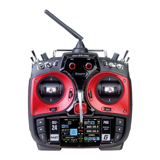
12 channel hott 2.4 ghz transmitter
Hide thumbs
Also See for mz-24 Pro:
- Manual (34 pages) ,
- Programming manual (241 pages) ,
- Programming manual (240 pages)

Related Manuals for GRAUPNER mz-24 Pro


Summary of Contents for GRAUPNER mz-24 Pro
- Page 1 Manual mz-24 Pro 12 channel HoTT 2.4 GHz transmitter No. S1006.PRO Part 2 Programming manual...
-
Page 2: Table Of Contents
Table of Contents General Operating Instructions REV/SUB ............... 64 THR.MIX - Throttle mixer ........176 THR.CUT / Motor - Throttle Cut / Motor Off ..66 Mixer - Basic Functions ........132 TX ctl - Transmitter Setting ........68 Programmable Mixers - General Information ..133 Timer .............. -
Page 3: Before Use
WARNING indicates the potential for serious Telemetry in-depth details about the advanced functions of the injury. Telemetry Data Display ......... 225 mz-24 PRO. Both manuals are available for down- CAUTION indicates possibility of lighter in- Programming Examples load at www.graupnerusa.com. juries. -
Page 4: Transmitter Start Up
When the transmitter is turned on the RF module will The Graupner-HoTT system allows more than 200 memory had once been linked to a Graupner-HoTT display the message: models or remote-control systems to be operated at receiver but is currently not detected. - Page 5 Press the SET button to pull up the BASE submenu • When training, linking or adjusting the remote CAUTION TX ctl: control, make sure that the transmitter an- Never turn off the transmitter while oper- tenna is always far enough from the receiv- ating the model! If this happens, wait three BACK TX ctl...
-
Page 6: Display Operation
Display Operation Operate the display by pressing value fields or icons To access the BASE, FUNCTION, SYSTEM and TE- The FUNCTION Helicopter menu selection display LEMETRY menu screens, press one of the four gear with a finger or the provided stylus: appears as follows: icons along the bottom of the basic display: the green 000%... - Page 7 The SYSTEM menu selection display appears as fol- The TELEMETRY display had no submenu selection. lows: The screen can differ depending on system settings. BACK BASE FUNCTION SYSTEM If the Outdoor disp option of the SYSTEM submenu Display is turned OFF , the TELEMETRY menu se- lection display appears as follows: Display ST mode...
-
Page 8: Warnings
Warning Displays Notice If a receiver is bound and saved into the model mem- There are two warning systems in the mz-24 Pro HoTT transmitter. Active warning pop-up screens ory, and there is an inactive Thr.POS warning, the RF Do not use the Servo Reverse option on Channel appear if receiver and transmitter operation statuses module will automatically turn on with the transmitter. - Page 9 Additional warnings may be triggered based on pow- triggered. To stop the mz system display screen from er and signal information, located in the mz-24 PRO automatically appearing, touch the ON ...
-
Page 10: Dsc Port
The standard two-pin DSC port on the back of the may have to be adapted by Graupner Service. mz-24 Pro HoTT transmitters is now used to function as a TRAINER / PUPIL port and as an interface for flight simulators or other external devices. -
Page 11: Audio Port
The card slot for micro-SD and micro-SDHC memory Removing the Memory Card on the back side of the mz-24 Pro HoTT transmitter: cards is found under the cover on the back side of the Open the cover on the back. Press the SD card gently mz-24 Pro HoTT transmitter: inwards to unlock the spring. -
Page 12: Micro-Usb Connection
Micro-USB Connection The Micro-USB port is found under the cover on the back side of the mz-24 Pro HoTT transmitter: To automatically receive email updates regarding import- ant product information and software/firmware updates, register all products on our website www.graupnerusa. - Page 13 Personal notes...
-
Page 14: Receiver Start Up
Notice On-board Voltage Display Reset With the mz-24 Pro HoTT transmitter, it is possi- To reset the receiver, hold down the SET button on the When a telemetry link exists, the current voltage of the ble to control up to 12 functions. Any servos receiver power supply appears in the main display to top of the receiver while turning on the power supply. -
Page 15: Installing The Receiver
Servo Connections and Polarity This holds true in particular for ON/OFF switches that are installed on model shells. Graupner-HoTT receiver servo connections are num- bered; the supply voltage runs through the numbered The receiver's servo and power supply connecting connections. The polarity of the plug-in system cannot cables should remain loose. -
Page 16: Installation Notices
• Servo arms must freely move throughout entire Graupner assumes no liability for products or acces- operating range. Make sure no linkage parts block sories produced by other manufacturers (unless oth- the servos movements. - Page 17 Never endanger people or dried. animals, fly close to power lines, oper- • Only use Graupner approved and recom- ate the model close to waterways or mended components and accessories. Al- open nautical traffic, near open roads,...
- Page 18 Only use original Graupner rechargeable batteries. Checking the Transmitter and Receiver Batteries When the warning message “Charge the battery!” appears in the display followed by a warning sound, immediately cease operation and recharge the trans- mitter battery.
- Page 19 Personal notes...
- Page 20 Graupner FS catalogue as well as on the V-cable PRX stabilized Choose a power supply that does not fail under a website www.graupnerusa.com.
- Page 21 (No. 3021). If the battery in the model With a traditional 4-cell pack, the Graupner HoTT sys- as newly released servos have permissible oper- is connected by a power supply cable (No. 3046, tem can be reliably operated providing that the above ating voltage range of 4.8 to 6 V.
-
Page 22: Safety And Handling
Charging Graupner LiPo/LiIo Batteries ies is 0... +50°C. Disconnect the battery, and place it on a non-flam- • Since Graupner|SJ GmbH is unable to monitor • Batteries as well as individual cells are not toys mable surface (such as concrete) until it cools whether the batteries are correctly charged and and must be kept ... - Page 23 This causes a loss of electro- of the usual balancer plug-in connection. lyte, gas formation or even explosions. Graupner Never directly solder on the battery cells. The LiIo/LiPo batteries should be kept away from and heat from direct soldering can damage battery •...
-
Page 24: Definition Of Terms
(e.g. a stopwatch turns on/off to The term "control channel" is used to describe the switches etc. Each switch can be assigned any num- measure engine operating times). The mz-24 Pro point at which a signal contains all control information ber of functions. - Page 25 Definition of terms...
-
Page 26: Control And Switch Assignment
Control and Switch Assignment Basic Procedure Many options and settings can be actuated to a con- Pressing the NONE button in any channel line will Deleting Controls or Switches trol function with a freely selectable control (ST1 - 4, bring up an active window. - Page 27 Assigning Logical Switch or Control Press any OFF button at any time to activate the BACK PHASE 1 D/R,EXP SERVO switch position. The value field will change to ON • Switch Assignment CH 2 and the switch graphic display will color in blue Logical switches can be assigned to a function (up), green (center), or red (down).
- Page 28 • Deleting Switches in the throw and press the button. The pre- The logical switch display window appears listing cise position point along the control and produc- the eight logical switches (L1 - L8) and eight invert- To delete, press the value field of the switch or es a value in the POS line.
- Page 29 • All of these switches can be given multiple assign- ments. Make sure that you do not accidentally as- sign competing functions to a switch. It is recom- mendable to write down the switching functions. Practical Examples: • Turning on/off an on-board glow plug heater when an idling switching point for the THR control stick is exceeded or undershot.
-
Page 30: Receiver Configuration
Receiver Configuration Vehicles, Boats and Drones This manual is grouped by model type. Refer to sec- tions of the appropriate model type for programming information specific to that model. For example, in- For drones there are basically four different ways of formation specific to vehicles, boats and drones, look assigning the four control functions (roll, nick, yaw for any/all of the following three icons to be highlight-... -
Page 31: Helicopter Models
In comparison to the receiver configuration of Models With 1 to 3 Swashplate Servos information specific to that model. For example, in- some older Graupner/JR transmitters, servo formation specific to helicopters, look for the follow- connection 1 (pitch servo) and servo connection... -
Page 32: Fixed-Wing Models
Receiver Configuration Motor-Powered Airplanes and Gliders This manual is grouped by model type. Refer to sec- Fixed-Wing Models With or Without Motor - Up to Delta/Flying Wing Models With or Without Motor 4 Ailerons and 4 Flaps - Up to 4 Ailerons/Elevators and 4 Flap/Elevator tions of the appropriate model type for programming Servos information specific to that model. - Page 33 Due to the different installation of the servos and rud- der linkages, the operating direction for certain servos can be reversed: Model Servo with Wrong Solution Type Rotation Direction V-Tail Reverse rudder and Invert the servos 3 elevator & 4 in the submenu REV/SUB Rudder correct, Switch servos 3 &...
-
Page 34: Program Description
Program Description To open the respective submenu, press one of the (BASE Menu) (FUNCTION Menu) four colored gear icons at the bottom right of the main The icons displayed in the FUNCTION submenu display: screen vary depending on the active model type and basic settings. - Page 35 Press the FUNCTION menu gear icon (blue “F”) to Press the FUNCTION menu gear icon (blue “F”) to Press the FUNCTION menu gear icon (blue “F”) to bring up the FUNCTION submenu screen: bring up the FUNCTION submenu screen: bring up the FUNCTION submenu screen: BACK BASE FUNCTION...
- Page 36 (SYSTEM Menu) (Telemetry Display) Press the TELEMETRY icon (blue “T”) to bring up the TELEMETRY display. The Telemetry display has no submenu icons but has differing screens depending Press the SYSTEM menu gear icon (purple “S”) to on system settings. By default, the receiver display bring up the SYSTEM submenu screen: appears: BACK...
- Page 37 Personal notes...
-
Page 38: Model Sel - Model Selection
Model selection Edit Model Memories 1 to 30 Turn off the receiver and the RF module of the trans- Then press the Model Sel submenu icon: BACK BASE FUNCTION SYSTEM M - # mitter. Press the value field line in the left side of the main display with a finger or stylus: Warning BACK... -
Page 39: Hott Synchronization Methods Setting
In the example below, the helicopter model named BACK MODEL NAME 1 NEXT “Starlet” is currently active. The model’s name is vis- MODEL NAME 1 ible in the active Model Memory line 01 as well as the Press HoTT Synchronization Methods Setting MODEL NAME 2 name bar at the top of the screen. - Page 40 Press NO to cancel. Press GLOBAL to change the CAUTION BACK MODEL NAME 1 NEXT selected model memory to Global (transmitter-specif- If a receiver system is accidentally MODEL NAME 7 ic HoTT-Synchronization): turned on after a model memory MODEL NAME 8 change, it will react to control move- MODEL NAME 9 IMP.M...
- Page 41 Press the button on the right side of the display (Create New Model) 000% 000% to Select the model: Warning 4.2V Tips Thr.HOLD Thr.CUT 000:00.0 BACK STARLET NEXT • To view model memory lines 07 and higher, press Thr.POS PHASE 000:00.0 0:01:23 STARLET...
-
Page 42: Model Name
Press < [DELETE] in the bottom row of the red key- Press the MAN. button at the top left to advance to pad to erase a single character. the next selection screen: Refer to the New Model Basic Settings - WIZARD section (page 44) for an example of programming a Press << ... - Page 43 Press the button to the right of the Wing Type line to switch between delta/flying fixed-wing models. A The default for "Motor Off" or "Idle" is Rear Thro Posi- different submenu appears depending on if the model tion. This can be changed to Front Thro Position for NORMAL ...
-
Page 44: New Model Basic Settings - Wizard
New Model Basic Settings - WIZARD Model Name BACK Graubele NEXT STARLET WIZ. A B C D E First-time users should utilize the Wizard function until Graubele Current Model Name comfortable inputting the information manually. EXTRA 360 IMP.M MODEL NAME 4 EXP.M The following example will describe programming a MODEL NAME 4... - Page 45 Model Type to the FUNCTION submenu Swash section (page Press the = [ENTER] button on the bottom of the red 172) for more information.) This example shows helicopter model. Press the blue keypad to transfer the model name from the blue field HELICOPTER icon: •...
- Page 46 • 3S 120(Nick) REV/SUB (Servo Reverse/Servo Sub Trim) Notices • It is only possibility to reverse the direction of WIZ. SUB.TR SERVO the servos connected to the output 6 (CH6) CH 1. 000% in a helicopter model and the output 1 (CH1) CH 2.
- Page 47 E.P.A (Servo Travel/Limit) Conversely, the effect of the control around neutral WIZ. E.P.A position increases for values less than 0% and de- CH 1. 150% 100% 100% 150% creases in the direction of the full deflection. The pro- CH 2. 150% 100% 100%...
- Page 48 Basic Operating Steps WIZ. PHASE 1 D/R,EXP WIZ. NORMAL PIT.CRV • Button ST OFF ST ON ROLL BACK TRIM Pitch min. Press this button to turn the graphic and nu- Curve meric display of the control stick position on Press Press +100% +100% –100%...
- Page 49 Between the two endpoints "L" and "H", up to Once the support point number and value ap- Press the X-axis button again to deactivate 5 additional support points can be set, and the pear in the POINT line, delete the point by the function and save the setting.
- Page 50 • TRIM Button WIZ. Remember that the input/output percentages in The mz-24 Pro transmitter software has a MIXER POINT PHASE the IN and OUT lines always refer to the momen- function that is integrated in the helicopter pro- NONE NONE...
- Page 51 To scroll through the available points (L, 1 to • PHASE Column WIZ. INC DEC 5 or H), press the buttons on To activate the governor during a specif- MIXER POINT PHASE the right side of the display. In the example ic phase, the phase must be selected.
- Page 52 Press the WIZ. button to return to the Pitch Curve THR.CRV (Throttle Curve) Notice display: The associated controller does not have any ef- The throttle curve can be specified by assigning up to fect if an undefined point is selected (in the basic 7 support points, along the entire control stick travel: WIZ.
- Page 53 (CH 7 in the Governor ACT To change the current value, touch the desired but- Graupner remote-control system). The gyro sup- Governor RATE 050% ton in the Governor ACR line. The display switch-...
- Page 54 IMP.M (Import From SD Card) WIZ. NORMAL Gyr/Gover There is an alternative emergency off option in the BASE Once a memory card is inserted into an operational submenu Throttle Cut (page 66). transmitter, a blue memory card icon appears at the 000% Gyro Suppression top right of the main display:...
- Page 55 Tips BACK STARLET NEXT The recall of each model type of the models saved on If a memory specific bound (and at the same time STARLET Press the memory card is performed as described in the BASE assigned to the SD card, eventually for safety rea- BEAVER submenu Model Type Display section (page 60).
- Page 56 EXP.M (Export to SD Card) From the list of saved models, select the memory to BACK STARLET NEXT be exported. In the example below, Memory Line 02 Use this option to export models saved in the trans- STARLET "Beaver" will be exported. Press to highlight the field. mitter to a memory card inserted into the transmitter's BEAVER The color of the field highlights blue:...
- Page 57 RES (Delete Model) If the model currently in use has been initialized, an BACK STARLET NEXT additional pop-up box will appear: To reset an assigned model memory using the RES STARLET button, open the BASE submenu Model Sel: BEAVER BACK MODEL NAME 2 NEXT GRAUBELE...
- Page 58 CPY (Copy Model Memory) BACK STARLET NEXT BACK STARLET NEXT To use the CPY button to duplicate a saved model STARLET STARLET memory to another model memory line by opening the BEAVER BEAVER BASE submenu Model Sel: GRAUBELE IMP.M GRAUBELE IMP.M EXP.M EXP.M...
- Page 59 BACK BASE FUNCTION SYSTEM Model Sel Model Type E.P.A REV/SUB THR.CUT TX ctl Timer Fail Safe Trim Step Servo CTL Set Out.Swap Telemetry Announce Base menu - Model selection...
-
Page 60: Model Type
Model Type Changing the Model Type Use this submenu to change the type or details of the The information screen for the currently active model The safety message "SURE?" appears: currently assigned model. will appear: BACK SURE? First, turn the receiver system off and turn the trans- BACK mitter's RF module off. - Page 61 To retain the model type but change a model setting, Press the ENT button at the lower right side of the BACK the same procedure is utilized. In the example be- display to return to the BASE menu display: low, the wing type of the current model needs to be changed from "1AILE"...
-
Page 62: E.p.a
E.P.A Setting the E.P.A End Point Adjustments allows definition of the maxi- The set values always correspond to the settings in BACK E.P.A SERVO the BASE submenu REV/SUB. mum servo travel for any channel. This feature is help- 150% 104% 097% 150% ful with components, such as wing flaps, that may get... - Page 63 Notice In contrast to the BASE submenu CTL Set, all the settings of the E.P.A submenu refer to the rel- evant servo independent of where the control signal for the servo comes from, i.e. either directly from the control element or from mix functions. Example The rudder servo of a model is directly controlled by the rudder control stick and also through an accessory...
-
Page 64: Rev/Sub
REV/SUB Setting Servo Direction and Neutral Position Setting the servo directions is necessary for to main- Servo Direction and Neutral Position 1. Setting Servo Direction tain the model's control system. Improperly set con- With this option, the servo rotation direction is Servo direction adjustments are done in the left REV trol movements will cause the model to crash. - Page 65 Notice Notice BACK SUB.TR SERVO Do not use the CH6 (helicopter) or CH1 (all other Move the trim control into the middle position CH 1. 000% models) servo reverse option to reverse the con- before changing the middle values. CH 2. 000% NEXT trol stick direction.
-
Page 66: Thr.cut / Motor - Throttle Cut / Motor Off
Throttle Cut Switchable Throttle Cut/Motor Off ignated in the value field of the SET line and needs to • In the Motor OFF position, the speed controller or be determined through experimentation. governor is disabled until the selected switch is not moved again. - Page 67 row keys ( pq ) to the left of the display screen to SERVO BACK PHASE 1 Thr.CUT achieve the same result. This adjustment allows the motor or engine to run at the desired idle speed or switches the engine or motor off: ...
-
Page 68: Tx Ctl - Transmitter Setting
To establish a connection with the transmitter, the WARNING ter settings, country settings, range test, transmitter Graupner HoTT receiver must first be bound to at least modulation and auto-save option. one model memory in the assigned Graupner HoTT In Global Mode a receiver system To configure the transmitter settings, from the main transmitter. - Page 69 Binding Multiple Receivers Per Model BACK TX ctl • RX2 can only be bound a receiver if there is already Multiple receivers can be bound to each model. In a bound receiver on RX1 . compatible receivers, users can directly manage up BIND ON/OFF to two receivers bound to each active model memo- •...
- Page 70 (Receiver Output) BACK SERVO PHASE 1 Out.Swap The mz-24 Pro HoTT transmitter allows users to dis- Notice CH >> OUT1 CH >> OUT7 tribute the transmitter control channels within a re- If for example you entered "2AILE" in the basic CH >>...
- Page 71 The numbering of the outputs (servo connections) and RF TYPE (Country Setting) the maximum number of available lines (outputs) cor- The specific RF type needs to be set to satisfy the Examples responds to the maximum number of servos that can relevant guidelines (FCC, ETSI, IC, etc.). •...
- Page 72 If this is not always the case, do not use the sys- RANGE TEST 99sec PPM18 tem and contact the Graupner Service Center. DSC OUTPUT AUTOLOG 10. Perform a range test before each flight, simulat- The selected modulation primarily influences the...
- Page 73 AUTOLOG (Auto-Save to SD Card) Press the ON/OFF button at the bottom right of the BACK BASE FUNCTION SYSTEM display while RF module is switched off to activate/ deactivate the automatic data logging save feature: Model Sel Model Type E.P.A REV/SUB THR.CUT...
-
Page 74: Timer
Timers Timer and Clock Settings The mz-24 PRO comes with two forward/backward Acoustic Signal Sequence BACK Timer timers, alarm, battery and model timers and a date/ 20 s before zero: 2 beeps TIMER1 T.RES time clock. Single beep every 2 seconds... - Page 75 Press the INC DEC button at the right edge of Notice BACK Press Timer the display or the arrow keys ( pq ) to the left of the If a timer is started, then stopped and switched display screen to increase/decrease time (between from forward to backward counting (or vice ver- TIMER2 T.RES...
- Page 76 3. Both Timer 1 and Timer 2 can be reset to the de- LAP SW (Lap Switch) LAP LIST fault value at any time by moving the switch as- Use this line function to count ground laps by follow- Press the >> ...
- Page 77 To reset the lap times to 00:00.0, press the CLR but- Date and Time The field highlights blue: ton: The third display page of the Timer menu is the date BACK Timer and time clock. BACK LAP TIME LAP TIME DATE 2016 NEXT 00: 00.
- Page 78 BATT TIME and MODEL TIME • BATT TIME Use the BATT TIME meter to monitor the total op- erating time of the transmitter battery. A switch cannot be assigned. When the transmitter is turned on and the battery voltage is noticeably higher than before, the timer is automatically reset to 00:00:00.
- Page 79 Personal notes...
-
Page 80: Fail Safe
Fail Safe In the Event of a Malfunction The Fail Safe function determines the response of the eliminates intermittent disturbances, such as drops in Programming receiver when the receiver system is turned on and if field strength, which would otherwise lead to "wob- To change between Hold and Fail Safe modes, press there is an interruption in transmission between the bles"... - Page 81 Move the control stick for this control channel into WARNING BACK Fail Safe SET the desired position and press the button at the • The fail safe settings stored in the MODE bottom right of the display to transfer the position into transmitter will not be automatical- CH 1.
-
Page 82: Trim Step - Trim Settings
Trim Settings Trim Settings Trimming allows models to fly straight and level with without looking at the display; when passing over To change the setting, press the button the control sticks in their central positions, and with middle position, a brief pause is inserted. the top left of the display: no input from the pilot. - Page 83 The field highlights blue: The example below shows controls T2, T3 and T4 The field highlights blue: with trim position adjustments: BACK SERVO PHASE 1 Trim Step BACK PHASE 1 Trim Step SERVO VIEW VIEW BACK SERVO PHASE 1 Trim Step STEP STEP VIEW...
- Page 84 Deleting Saved Trimming Positions Programming Refer to the Programming Examples section (page Press to highlight the field with the trimming value to Press the button in the line of the desired control. In 230) for trim setting examples. be deleted. In the example below, T3 needs to be the example below, D.TRIM 1 needs to be reassigned: reset: Press the...
- Page 85 AUTO TRIM At the same time the control sticks can be released to the normal position, as shown below: The AUTO TRIM function allows users to quickly and easily to trim a model, for example during the first BACK PHASE 1 Trim Step SERVO flight or after large upgrades, repairs, etc.
-
Page 86: Servo - Servo Monitor
Servo Monitor Servo Positions / Servo Test Function Display Use this display to check servo settings, program set- PHASE 1. (Additional phases will be named numer- Helicopter models tings into different phases, and test and change servo ically, e.g. Phase 2, Phase 3, etc.) To define multi- ple phases, refer to the FUNCTION submenu Phase settings prior to use. - Page 87 • The number of channels displayed in this Servo test Press the INC DEC button at the right edge of menu refers to the maximum control chan- the display to increase/decrease the value in .05s in- Notice nels available in the transmitter. The number crements.
- Page 88 Touch NO to terminate the procedure. Touch YES to start the servo test function. This func- tion automatically controls the servos operating under the assumption that the associated controls (starting from the neutral position) will be simultaneously and continuously moved back and forth between -100% and +100% during the set period.
- Page 89 Personal notes...
-
Page 90: Ctl Set - Control/Switch Setting
• When assigning several functions to the same switch, note that incorrect responses may Across the top of the mz-24 Pro HoTT transmitter are arise, i.e. using the same switch to change the dials and switches for servos responding to con- Phases and control Phase Trimming. - Page 91 CTL Column (Control/Switch) The active Select window appears: BACK PHASE 1 CTL Set SERVO Assigning Switch or Control SERVO BACK PHASE 1 CTL Set Press CH 5. NONE 000% 100% 100% NEXT Select CH 6. SL 2 000% +100% +100% CH 5.
- Page 92 Notices Press the Offset value to be changed. In the example -TRAVEL+ Column below, the offset for CH8 needs to be increased: • The controllers assigned in this sub-menu Use this column to set the travel of each control ele- globally affect all the phases.
- Page 93 Use the same procedure for a value on the plus side The field highlights to blue: Notice of the control travel, for example: Use this setting to set a symmetrical delay for the BACK PHASE 1 CTL Set SERVO transmitter-side control signal with the stan- BACK PHASE 1 CTL Set...
-
Page 94: Throttle Limit Function
Thr.POS PHASE to program both phases. Normal signal Instead of THR.HOLD, the mz-24 Pro HoTT transmit- Please select RF ON/OFF ter offers more precise options for adjustment, such as increasing the system speed below hovering to increase flexibility. - Page 95 6 travel in the BASE tle Curve display, adjust Point L to approximately +15 the mz-24 Pro HoTT transmitter that servo output 6 submenu E.P.A (page 62). to +18%, as shown in the example below: controls the throttle servo.
-
Page 96: Out.swap - Transmitter Output
( pq ) to the left of the channels to transmitter outputs 1 - 12 according to display screen to achieve the same result. Example personal preference: In the helicopter program for the mz-24 Pro HoTT Press the RES button to reset the changed value BACK Out.Swap... - Page 97 Notice The mz-24 Pro allows the 12 transmitter control channels to be assigned according to personal preference in both single receivers as well as mul- tiple receivers. Refer to the Channel Mapping section (page 104) of the BASE submenu Telemetry (page 98).
-
Page 98: Telemetry
Telemetry Settings and Displays Receiver settings and the displays and settings of the The HoTT receiver should be reinitialized be- BACK Telemetry connected telemetry sensors can be retrieved and fore use in another model. Refer to the Re- RX SELECT ALWAYS programmed in real time in the Telemetry menu. - Page 99 • To avoid accidental starts, models and Telemetry If you have bound a receiver as RX1 or RX2 in the sensors should only be programmed BASE submenu TX ctl, then designate one of the two To change the telemetry settings, from the main dis- when the model is on the ground with receivers as the "telemetry-receiver"...
- Page 100 Specifically, there is the possibility of back-channels re- Press the INC DEC buttons to change the value SET ciprocal interference, e.g. a camera drone with separate within the selected range. Press the button to camera and drone control or a towing model for mod- confirm and store to the receiver memory.
- Page 101 SETTINGS AND DISPLAYS SETTING & DATA VIEW Consequently, the reception shown in dBm in the dis- L.R-VOLT Last receiver current operating volt- play is generally negative. The higher the number after Press the “>>” brackets in the SETTING & DATA VIEW age since the previous time the re- the minus sign, the worse the reception.
- Page 102 R-TEM. (Receiver Temperature) CAUTION Value Explanation Settings Always keep an eye on the receiver's op- The receiver temperature must remain within an ac- V#.## Receiver firmware None erating voltage. If it is too low, do not op- ceptable range during all flight conditions (ideally be- version tween -10°...
- Page 103 A separate adjustment for both directions can be en- BACK Telemetry BACK Telemetry tered between 30% to 150%. RECV RECV RX SERVO V6.35 < > RX SERVO V6.35 < > Default factory setting: 150%. >OUTPUT CH : OUTPUT CH : REVERSE REVERSE PERIOD...
- Page 104 Consult with an experienced pilot (transmitter con- for settings tailored to the specific model being used. menu. trol channel) The 12 control channels (INPUT CH) of the mz-24 Pro The Switch-On Fail Safe function should always be MODE Fail safe mode HOLD can be similarly set by assigning the servo connec- utilized;...
- Page 105 The setting programmed under MODE always refers The setting is made in 10-μs increments, as shown FAIL SAFE ALL (Global Fail Safe Setting) to the channel set in the line OUTPUT CH. below: This selection allows you to easily determine the ser- The default factory setting for all servos is HOLD.
- Page 106 RX FREE MIXER BACK Telemetry BACK Telemetry RECV RX FAIL SAFE V6.35<> RX FAIL SAFE V6.35 < > RECV BACK Telemetry >OUTPUT CH : >OUTPUT CH : RX FREE MIXER V6.35 < > INPUT CH RECV INPUT CH >MIXER MODE HOLD MODE HOLD...
- Page 107 Notice • NORMAL RX CURVE If you have already programmed mixer functions This setting corresponds to the classic airplane With the RX CURVE function, you can administer con- in the FUNCTION submenus Wing MIX or Prog. type with a rear tail and separate rudder and ele- trol characteristics for up to three servos: MIX, pay special attention to ensure that these vator.
- Page 108 Generally, a nonlinear control function is used for the The servo reacts strongly to control stick move- In order for the connected device to be correctly iden- aileron (channel 2), elevator (channel 3) and rudder ment around the neutral position. The curve be- tified by the receiver, servo connection 5 MUST be (channel 4).
- Page 109 RX SERVO TEST ALARM Alarm threshold when -20 to +10 °C BACK Telemetry With the RX SERVO TEST function, you can test the TEMP– the receiver tempera- default factory RECV RX SERVO TEST V6.35 < servos connected to the currently active receiver: ture is too low setting: -10 °C ALL-MAX...
- Page 110 When the voltage falls below the set alarm threshold, CH OUTPUT TYPE (Connection Type) This is recommended for digital servos when sev- a warning tone sounds, and VOLT.E appears in white eral servos are used for a single function (i.e. an ai- In this line, select the type of servo control or signal at the top right in all RX displays: leron) so that the servos are fully synchronized.
- Page 111 Press SET again to confirm selection and move By contrast, GR-32 DUAL receivers (No. 33516) This receiver configuration is recommended when to the channel selection field: have their own aggregate signal connection at the flight direction can restrict range, for example, if bottom left identified with - + S.
- Page 112 • SUMD (Digital Sum Signal) BACK Telemetry BACK Telemetry A HoTT receiver configured as SUMD always gen- RECV RECV RX SERVO TEST V6.35 < RX SERVO TEST V6.35 < erates a digital aggregate signal from the control ALL-MAX : 2000µsec ALL-MAX : 2000µsec signals of a selectable number of its controls chan-...
- Page 113 >> SENSOR ALARM TEMP+ : 55°C >> ALARM TEMP– : –10°C RF STATUS VIEW The mz-24 Pro HoTT transmitters automatically recog- CH OUT TYPE : ONCE Press >> VOICE TRIGGER nize any sensor(s) connected to a switched on receiver or sensor(s) that have been connected after the power If a sensor was recognized by the receiver after it supply is turned on.
- Page 114 RF Status Display To open the RF Status submenu, press the button in Value Explanation the RF STATUS VIEW line: Quality (in percent) of the signal packages from the receiver arriving at the transmitter BACK Telemetry RX SELECT ALWAYS Quality (in percent) of the signal packages >>...
- Page 115 Personal notes...
- Page 116 VOICE TRIGGER To open the Voice Trigger submenu, press the button An active display box appears: • As soon as the transmitter and/or the receiver have in the VOICE TRIGGER line: been switched on, the system starts to search the BACK Telemetry connected sensors.
- Page 117 • Automatic Sequential TRANSMITTER RECEIVER If switches assigned to the REPEAT and TRIGGER Press the bracket button in the TRANSMITTER line: Press the bracket button in the RECEIVER line: lines are activated, all the announcements includ- BACK Telemetry BACK Telemetry ed in this menu and its submenus will be repeat- REPEAT NULL...
-
Page 118: Announce - User Voice Recordings
Use this column to activate, according to the switch NULL position and phase, a User_Voice announcement. Saved in the mz-24 Pro HoTT transmitter memory, Press the value field in the ANNOUNCEMENT col- Refer to the Control and Switch Assignment section... -
Page 119: Function Menu
FUNCTION Menu BACK PHASE 1 Announce SERVO PHASE ANNOUNCEMENT SW 3 NEXT NULL NULL NULL NULL Press the INC DEC buttons to scroll through the voice file list: BACK SERVO PHASE 1 Announce PHASE ANNOUNCEMENT SW 3 285_User_Voice_ NEXT NULL NULL NULL... -
Page 120: Phase
The underlying schema is de- sets of trim settings according to the flight phase (i.e. scribed as follows: takeoff, landing, etc.). The mz-24 PRO HoTT trans- Phase display for all models (except helicopters): • If all flight phase switches, if any, are open (i.e. - Page 121 Phase Setup Value fields appear in the SLOW and CTL columns: • CPY button (Copy) The phase setting fields of any phase line high- • PHASE Column BACK NEXT PHASE lighted blue can be copied to any another phase To set up the first phase, press the appropriate PHASE SLOW line by pressing the...
- Page 122 In the example below, the target field was • DEL Button (Delete) To set the delay time, press the field for the appro- changed from PHASE 2 to PHASE 4: priate phase in the SLOW column: The phase information of any phase line highlight- ed blue can be deleted by pressing the DEL ...
- Page 123 An active display pops up: The following display appears: BACK PHASE NEXT BACK PHASE 1 Phase PHASE SLOW PH. VOICE 1 Select Attention NORMAL 1.2s PH. VOICE 2 In the helicopter AUTOROT phase, always START 0.0s NULL PH. VOICE 3 leave the standard delay time as 0.0s.
-
Page 124: D/R,Exp
D/R,EXP Control Attitude Settings for Control Functions 2, 3 and 4 The dual rate/expo function allows users to assign switches and phases to change or influence the con- trol deflections and characteristics of channels 2, 3 For all CARS, BOATS or DRONES, the channel set- For all AIRPLANES or GLIDERS, the channel setting and 4. - Page 125 full deflection is allowed when the stick is moved to BACK PHASE 1 D/R,EXP SERVO its limit. CH 3 Conversely, the effect of the control around center po- sition increases for values less than 0% and decreas- +100% +100% es in the direction of full deflection. The progression 000% 000% Press...
- Page 126 Setting Asymmetrical Dual Rate Values Exponential Function BACK PHASE 1 D/R,EXP SERVO Set the exponential function the same way as the dual To set individual dual rate values, make sure the SYM AILE rate function. OFF line value button is .
- Page 127 BACK PHASE 1 D/R,EXP SERVO AILE +100% +100% +025% –050% Press the INC DEC button at the right edge of the display to increase/decrease the values. Alterna- tively, press the arrow keys ( pq ) to the left of the display screen to achieve the same result.
-
Page 128: Thr.crv
Changing the Control Direction the FUNCTION menu gear icon (blue “F”) to bring up POINT +100% the FUNCTION submenu screen: In the mz-24 PRO transmitter, all fixed-wing rear ST ON X-axis Y-axis throttle positions default to Motor OFF when using... - Page 129 The graphic display makes it much easier to specify BACK PHASE 1 THR.CRV SERVO the support points and their adjustment. However, it BACK PHASE 1 THR.CRV SERVO is recommended to start with fewer support points. Curve In the basic setting of the program, 2 support points –100% Curve describe a linear characteristic, that is, the two end-...
- Page 130 When the control stick is moved and the green line Press the ENT button to remove the point: Notices moves off the green point, the point will turn red, • Moving the red point horizontally away SERVO BACK PHASE 1 THR.CRV the ? is replaced with a number, and the point val- from the current control position will cause...
- Page 131 Rounding Off the Throttle Curve • CURVE Line ON/OFF Button Curve profiles are angeled by default. Automati- cally round off the lines by turning ON the round- ing function in the CURVE line: BACK PHASE 1 THR.CRV SERVO CURVE –030% Press +035% POINT...
-
Page 132: Mixer - Basic Functions
Example: V-tail Mixer elevator stick rudder / elevator left V-tail mixer rudder / elevator right rudder stick The program of the mz-24 Pro HoTT transmitter al- ready contains numerous preprogrammed coupling 132 What is a mixer? -
Page 133: Programmable Mixers - General Information
Programmable Mixers - General Information Each fixed-wing and helicopter model memory pro- Essential Mixer Parameters gram has five programmable linear mixers and three • Mixing degree that determines the level of influ- curve mixers in each of the 30 model memories per ence of the input signal on the control channel programmed phase in which users can define inputs connected to the mixer output. -
Page 134: Prog.mix - Programmable Mixer
Programmable Mixers Programmable Linear and Curve Mixers In addition to the different model types, per each Page Change The Master >> Slave (source >> target) selection dis- set-up phase there are five linear mixers and three play page for the mixer appears: Linear mixers (1 to 5) are shown on the first display 7-point ... - Page 135 The button highlights blue: To store the selected settings, press the BACK but- BACK PHASE 1 Prog.MIX SERVO ton at the top left of the display: NONE NONE SERVO >> BACK PHASE 1 Prog. MIX SERVO NONE BACK PHASE 1 Prog.
- Page 136 Activating and Deactivating Mixers Both the MST and SLV column buttons will open the Press the CLR button to reset both default values in channel selection display screen: the blue and black MST and SLV fields: To activate (ON) or deactivate (INH) a mixer that has been setup as described above, press the value field BACK SERVO...
- Page 137 The mixer settings display page appears: TRIM Line The field highlights blue: It is standard that the digital trim of control functions BACK PHASE 1 Prog MIX SERVO BACK PHASE 1 Prog.MIX SERVO 1-4 act on the mixer input. The digital trim for con- >>...
- Page 138 • OFFSET X Press the RES button to reset the changed value Press the RES button to reset the changed value back to the default. back to the default. A value unequal to 000% entered in the OFFSET X line causes the offset to shift horizontally by a •...
- Page 139 An active window pops up: CH8 is assigned to the side proportional rotary control Move the green line via the related control. To set a ST OFF ENT SL1.) To show the green line, press the but- support point, press the button: BACK SERVO PHASE 1...
- Page 140 are automatically renumbered sequentially from left to BACK PHASE 1 Prog.MIX SERVO BACK PHASE 1 Prog.MIX SERVO right after points are set or deleted. TRIM >> CH10 TRIM >> CH10 Deleting a Support Point To remove a set support point, move the control stick +050% +050% until the vertical green line aligns with the point to be...
-
Page 141: Trainer
Dual Transmitter Connection With DSC Cable Notice To transfer any of the control function inputs 1 - 12 to An mz-24 Pro HoTT TEACH transmitter can be con- TEACH nected to any suitable PUPIL transmitter, including the PUPIL, press the button. - Page 142 CH 3. PUPIL CH 9. TEACH BIND "Module" line of the BASE submenu. Otherwise, the With Graupner transmitter series mc, mx, or mz it is CH 4. PUPIL CH 10. TEACH PPM signal at the DSC socket may be inverted.
- Page 143 M side and a 3-pin jack ing in middle position after transferring control plug on the S side. (Example: an mz-24 Pro functions to the PUPIL transmitter. to an mc-16, or a transmitter retrofitted with •...
-
Page 144: Connecting Scheme
Connecting Schema The following connecting schema represent all transmitter combinations possible at the time this manual was created. Pupil transmitter mz-24 Pro HoTT Teacher transmitter mz-24 Pro HoTT DSC cable Trainer cable No. 4179.1 No. 4179.1 Trainer cable Trainer cable No. 3290.8 No. -
Page 145: Wireless Hott System
BIND Failure to assign a control in the PUPIL transmit- Transfer up to twelve function inputs of an mz-24 Pro ON/OFF line of the BASE submenu TX ctl be set ter will result in the relevant servo(s) remaining in TEACH transmitter to the PUPIL transmitter, either in-... - Page 146 Immediately press the same button on the TEACH BACK Trainer SERVO transmitter: PUPIL TEACH CH 1. CH 7. CH 2. PUPIL CH 8. TEACH SW 8 BACK Trainer SERVO Following the standard conventions for model types CH 3. PUPIL CH 9. TEACH BIND CH 1.
- Page 147 000% 000% 4.2V Training Mode RX 05.5V 000:00.0 No pupil signal During training, the teacher and pupil can maintain a 000:00.0 0:01:23 comfortable distance. Do not exceed a distance of 164 feet (50 m). No one should be between the teach- M - 1 PHASE 1 er and pupil: this reduces the feedback channel range...
-
Page 148: Logical Sw - Logical Switch
Logical Switch Logical Switch Setup This function allows two switches, controls and/or log- The result of a logical switch is that it can be used as AND / OR ical switches (or any combination thereof) to be inter- alternative switch function. The ON/OFF column in Changing the switch connection between ... - Page 149 Once the parameters are established in the FUNC- TION submenu Logical sw display, assign the logical switches to a switch. In many submenus there is a CTL option. By pressing any CTL field the following active window will appear: Select Press LOGIC Pressing the...
-
Page 150: Sequence - Sequencer
Sequencer Logical Switch Setup A sequence allows up to three servos to perform up to Through the Sequence display, one common switch • Activation / Deactivation nine steps during a 30-second period. For example, can be assigned to activate up to three servos per- The control channels specifically required for the sequencing can allow the cover doors to open while forming up to 9 precisely determined steps within 30... - Page 151 Repeat the process for the other two channels. example below, the time delay is set for 4.5s. The BACK Sequence SERVO vertical line, representing the time flow, moves to Press the RES button to reset the changed value the right while the angled lines, representing the back to the default.
- Page 152 Notice Switch Assignment action on those controls may lead to process malfunction. The sequencing examples shown are for To assign an activation switch to the completed se- demonstration purposes only and do not rep- quence, follow the instructions in the Control and •...
- Page 153 Common Function Menus Helicopter Model Function Menus Personal notes...
-
Page 154: Pit.crv - Pitch Curve
Pitch min Line +100% control travel) and the control (placed in the Phase-dependent settings of the pitch curves In the mz-24 Pro, the helicopter program defaults the center). "rear" throttle to the Pitch min position. This submenu allows for different phase-specific val- This option allows users to easily reverse the pitch ues to be programmed. - Page 155 Basic Operating Steps point to be deleted. The support point will turn red BACK PHASE 1 PIT>>TAIL SERVO and its number and associated value will appear in • ST OFF ST ON Button TRIM Pitch min. FORWARD the POINT line. Press the ENT ...
- Page 156 Button NONE NONE Press NONE NONE Notice The mz-24 Pro has a function integrated in the NONE NONE helicopter program that allows trimming up to Remember that the percentages in the input NONE NONE six throttle curve and pitch curve support points...
- Page 157 The following appears in the display: Notice BACK SERVO The associated controller does not have any MIXER POINT PHASE SERVO BACK effect if an undefined point is selected (in the SL 1 THR.CRV NONE MIXER POINT PHASE basic version of the relevant curve mixers, NONE NONE NONE...
- Page 158 Autorotation Setting Notice In a powered flight, the maximum wing angle is lim- Approach angle ited by the available motor output; in autorotation When selecting a phase that has not been de- flight, however, it is limited by the stall at the main fined, by default only Phase 1 is active and the in strong wind...
- Page 159 Function menu | Helicopter model - Pitch curve...
-
Page 160: Thr.crv - Throttle Curve
= +100% control travel) and the control (placed in the a gas preset, as is sometimes used in other remote ues to be programmed. Phase names are displayed control systems. The mz-24 Pro transmitter allows center). in green in the upper left side of the screen next to... - Page 161 To start the gas motor, make sure that the THR.Limit Notices The Travel setting of the throttle limiter may is closed, i.e. the carburetor can only be adjusted by have to be adapted in each phase by chang- • Use the Throttle Limit Function (page 94) trimming its idle position.
- Page 162 L (input = 0%) and H (input = +100%) to the same curve of the motor with collective blade adjustment). value, as shown below: Notice The mz-24 Pro transmitter allows the throttle, pitch Electric drives do not require an idle setting, and torque compensating curves to be independently BACK PHASE 1 THR.CRV...
- Page 163 Different phase-dependent throttle curves are pro- CAUTION 2. The model lifts off before the pitch control stick reaches center position: grammed for optimum hovering and aerobatics ad- Before starting the motor the first time, justment: become familiar with the dangers and a) The speed is too high •...
- Page 164 speed should remain constant, matching the hover rettor is open too wide or if the speed controller is set speed setting. too high, there is a danger that the motor will start at a high speed once it is turned on, and the centrifugal If the speed decreases while climbing even though the clutch will engage immediately.
- Page 165 Function menu | Helicopter model - Throttle curve...
-
Page 166: Gyr/Gover - Gyro/Governor
000:00.0 Notice on page 166). Many current standard gyro systems do not re- With the Graupner/JR-Gyro NEJ-120 BB, No. 3277, 000:00.0 0:01:23 quire this option to be utilized; consult the gyro both the bottom and top values are set: control 1 sets... - Page 167 Various Gyro Sample Settings For example, for purposes of illustration, below are If the model is flying forward at high speed or hovering plotted gyro gain values in relation to tail rotor deflec- in a powerful headwind, the net result of the stabilizing •...
- Page 168 Most of the current gyro systems can be adjusted for Governor ACT Line BACK PHASE 1 Gyr/Gover SERVO a smooth, proportional effect. Choose between two BACK PHASE 1 Gyr/Gover SERVO different modes of action in the transmitter. 000% Gyro Suppression If the gyro has one of these options, the alternative Gyro Gain 000%...
- Page 169 Personal notes...
-
Page 170: Thr.hold
THR.HOLD Autorotation Throttle Position Throttle hold sets the throttle to a percentage of the • SET line engine idle, regardless of collective pitch stick posi- An alternative emergency-off function is located in the Use this option to move the throttle a percentage tion. - Page 171 BACK PHASE 1 THR.HOLD SERVO SW 3 –100% Press the INC DEC buttons or the arrow keys ( pq ) to increase/decrease the value until the red and green arrows are equal: BACK THR.HOLD SERVO PHASE 1 SW 3 –111% ...
-
Page 172: Swash - Swashplate Mixer
Swash Pitch, Roll and Nick Mixer This submenu option is not available for the model set- evation and pitch axis are activated so that additional BACK Swash SERVO ting 1SERVO NOR. mixers do not need to be defined. PITC ROLL If the model is controlled using a separate pitch ser- +061% +061%... -
Page 173: S.limit - Swashplate Limiter
S.Limit Adjustable Limitation and Deflection Rotation Swash Rotation This function acts like a circular mechanical fence lim- BACK S.Limit SERVO iting the maximum possible tilting of the swashplate With some rotor head controls, it is necessary to tilt for aileron and elevator. the swashplate in different direction than the intend- To adjust these settings, from the main display press ed rotor plane angle during cyclical control, i.e. -
Page 174: S.mix - Heli Mixer
S.MIX Phase-Dependent Pitch, Roll and Nick Settings The following trim options are used for compensat- different switch. To change the phases, activate the The settings display screen opens: ing asymmetrical helicopter reactions to control com- corresponding switch(es). SERVO BACK PHASE 1 S.MIX mands and to adjust helicopters with multi-blade ROLL >>... - Page 175 Press the INC DEC buttons or the arrow keys ( Notice To save and exit to the FUNCTION menu, press BACK pq ) to increase/decrease the value: button at the top left of the screen. The mixed values portrayed in the above graphics are for demonstration purposes only BACK PHASE 1...
-
Page 176: Thr.mix - Throttle Mixer
THR.MIX Phase-Dependent Throttle Tracking with Roll, Elevation and Tail Settings Use this function to individually adjust throttle track- Phase-Dependent Settings • SET Column (Setting) ing with roll, pitch and tail control. To bring up the phase settings screen, press the This submenu allows for different phase-specific val- The throttle needs to follow an increase in pitch and bracket buttons... - Page 177 The value field highlights blue: When the phase is activated by turning the ON BACK PHASE 1 THR.MIX SERVO button in the ACT Column, the assigned switch ROLL >> THRO SERVO BACK PHASE 1 THR.MIX will perform the adjustments made in the SET dis- Press RATE ROLL >>...
-
Page 178: Pit>>Tail
PIT>>TAIL Phase-Dependent Static Torque Compensation Use this function to adjust the torque compensation refer to the FUNCTION submenu Phase section (page Change the trim using the digital tail rotor trim control curve with a linear mixer ratio. In normal flight, the tail 120). - Page 179 Helicopter Model Function Menus Fixed-Wing Model Function Menus Function menu | Helicopter model - Pitch >> Yaw...
-
Page 180: Idle Low
Idle LOW Idle Stabilization Setting This submenu option is not available for models using In the SET line, set the desired corrective value by BACK PHASE 1 Idle LOW SERVO an electric motor. pressing the value field: BACK PHASE 1 Idle LOW SERVO Use this function to set a gas motor’s idle. -
Page 181: Snap Roll
Snap Roll Automated Programming A snap-roll is a purposely accelerated stall resulting the BACK button. Standard default naming for the Press the button in the ACT column to activate ON phases are usually displayed as NORMAL/PHASE INH in a “spin”. This function enables up to four pre-pro- or inhibit the settings: 1. -
Page 182: Aile Diff - Aile Differentiation (Motor Airplane)
Aile diff - Plane Aileron Travel and Differentiation Settings This submenu option is not available for models using To adjust these settings, from the main display press BACK PHASE 1 Aile diff SERVO the FUNCTION menu gear icon (blue “F”) to bring up the 1AILE and 1AILE1FLAP settings. - Page 183 To change a value, press the appropriate value field. To save and exit, press the BACK button at the top In the example below, the selected aileron travel must left of the display to return to the previous menu. be changed to 066%: BACK BASE FUNCTION...
-
Page 184: Aile Diff - Aile Differentiation (Glider)
Aile diff - Glider Aileron Travel, Differentiation and Differentiation Reduction Settings This submenu option is not available for models using one aileron is almost impossible, though depending different switch. To change the phases, activate the the 1AILE and 1AILE1FLAP settings. on the position and degree of differentiation, often it corresponding switch(es). - Page 185 Display Page Travel Setting Press the INC DEC buttons or the arrow keys To set the differentiation, press the appropriate val- ue field of the Diff. column. In the example be- ( pq ) to increase/decrease the value: The adjustment range of 100% to both sides allows low, the selected aileron travel must be changed the adjustment of different deflections on the right SERVO...
- Page 186 mitter is held. A value equal to the set percentage Press the INC DEC buttons or the arrow keys of the aileron differentiation means that this is re- ( pq ) to increase/decrease the value: moved in maximum butterfly function (flaps com- Aile diff SERVO BACK...
- Page 187 Personal notes...
-
Page 188: Wing Mix - Wing Mixer
Wing MIX Wing Mixer Adjustment Use this function to adjust the rudders, ailerons and Programming control (which cannot be independently reset), a con- elevators to fix deflection direction during flight. trol switch or a logical switch. • ACT Column (Active) To adjust these settings, from the main display press To activate ON ... - Page 189 The field highlights blue: To save and exit, press the BACK button at the top The adjustment should normally be symmetrical with left of the display to return to the previous menu: the neutral point of the aileron control stick. BACK PHASE 1 Wing MIX...
- Page 190 The field highlights blue: To save and exit, press the BACK button at the top To set the mixer, press the >> button in the RUD- D>>ELEV line: left of the display to return to the previous menu: SERVO BACK PHASE 1 WING MIX...
- Page 191 The field highlights blue: To save and exit, press the BACK button at the top left of the display to return to the previous menu: BACK PHASE 1 Wing MIX SERVO RUDD >> ELEV BACK PHASE 1 Wing MIX SERVO RATE RUDD >>...
-
Page 192: Flap Mix - Flap Mixer
Flap MIX Flap Mixer Adjustment This submenu option is not available for models using different switch. To change the phases, activate the FLAP Line the 1AILE and 2AILE settings. corresponding switch(es). By pressing the >> button in the FLAP line, one of three display screens will appear, depending on the BACK PHASE 1... - Page 193 If a switch was assigned to CH6 in the BASE sub- • OFFSET Line BACK PHASE 1 Flap MIX SERVO menu CTL Set and in the FUNCTION submenu Use to set the phase-specific positions for all of FLAP Flap set the ACT line is set to INH : the flaps in the respective model.
- Page 194 settings saved in CTL Set (control posi- AILE >> FLAP Line BACK PHASE 1 CTL Set SERVO tion), Flap MIX (offset value and travel set- Use this line to adjust phase settings for flap pair ting) and Flap set (RATE values). movement when the aileron is actuated.
- Page 195 Notice The flaps uniform default values are +30%: The setting can be symmetrical or asymmetrical to the flap control center point. The available setting options depend on the BACK SERVO SPEED Flap MIX number of ailerons selected during the basic set- The adjustment range is ±125%.
-
Page 196: Flap Set
Flap Set Flap Servo Effect Adjustment This submenu option is not available for models using This example shows the display for setting a maxi- Programming mun, such as 4AILE4FLAP: the 1AILE setting. • ACT Column (Active) • ACT = INH OFF ... - Page 197 If a switch or control assigned to CH6 in the Notice BACK PHASE 1 FLAP MIX SERVO BASE submenu CTL Set, then all the provid- Because of redundancy, only set one of FLAP ed flaps move in the respective positions cor- the aforementioned submenus with the responding with the settings saved in CTL Set precise values.
- Page 198 Notice Press the INC DEC buttons or the arrow keys ( pq ) to increase/decrease the value current value If you switch this function OFF via an as- Typically, in the BASE submenu CTL Set, no control is within a range of ±100%: signed switch, not only is the phase trim de- assigned to the inputs CH5-CH12.
- Page 199 Personal notes...
-
Page 200: Airbrake
Airbrake Airplane Braking System Adjustment This submenu option is not available for certain model This example shows the display for setting a maxi- • ACT Line (Active) mun, such as 4AILE4FLAP: types and configurations. To activate ON or inhibit INH a specific phase, press to change the value fields on the appropri- BACK... - Page 201 To bring up the flap setting screen, press the NEXT To save and exit, press the BACK button at the top BACK LANDING Airbrake SERVO button at the right edge of the display. Use the same left of the display to return to the previous menu. SW 6 procedure described above to adjust all value fields: NEXT...
-
Page 202: Butterfly
Butterfly Glider Braking System Adjustment This submenu option is not available for certain model From the FUNCTION submenu, press the Butterfly Phase-Dependent Settings types and configurations. icon: This submenu allows for different phase-specific val- ues to be programmed. Phase names are displayed BACK BASE FUNCTION... - Page 203 BUTTERFLY OFF Line Move the control element assigned to the input CH1, After the brake offset, which is necessary for the cor- rect operation of the flaps, set the RATE line of this (by default the throttle/brake control stick) to the po- The selected offset or BUTTERFLY OFF point deter- sition at which the flaps are to be retracted or closed.
- Page 204 RATE Line Press the RES button to reset the changed value The green, vertical bar in the graphic display indicates back to the default. the brake control position. The bar moves away from A symmetrical or an asymmetrical effect can be de- the edge of the graph as soon as the throttle/brake To access the flaps setting screen, press the NEXT ...
- Page 205 To save and exit, press the BACK button at the top left of the display to return to the previous menu: BACK BASE FUNCTION SYSTEM Phase D/R,EXP THR.CRV Prog.MIX Snap roll Aile diff Wing MIX Flap MIX Flap set Butterfly Trainer Logical sw Sequence...
-
Page 206: V-Tail
V-Tail V-Tail Actuation Adjustment This submenu option is only available for model types different switch. To change the phases, activate the BACK PHASE 1 V-Tail SERVO corresponding switch(es). with a V-Tail configuration. ELEVATOR RUDDER The elevator and rudder are controlled by two sepa- rately-articulated rudders arranged in a V-shape. -
Page 207: System Menu
Fixed-Wing Model Function Menus System Menus Personal notes... -
Page 208: St Mode - Control Mode
ST mode Model-Specific Basic Control Settings There are four different control function possibilities boat control assignments on the control codes of air- Helicopter Model to assign to the control sticks. Individual options are craft fractions in order to avoid conflicts after a model MODE 1 (throttle right) MODE 2 (throttle left) chosen based on country settings, pilot preferences,... - Page 209 ST mode BACK ST MODE: FRONT AILE RUDD ELEV THRO Press the BACK button at the top left to return to the SYSTEM menu. System menu - ST mode...
-
Page 210: Warning
Warning Model Memory Specific Warning Settings Use this menu to turn off or on the five visual and The Power OFF time option allows users to specify Warning BACK acoustic alarm triggers. Typically, only the throttle how long the transmitter should wait before begin- servo (CH1-POS) is actively monitored. - Page 211 Personal notes...
-
Page 212: Etc. Set
Locked transmit- Enter a password with a maximum of 14 characters. ters will need to be sent to the Graupner Ser- The entered characters will appear in the blue input vice Center for reset. - Page 213 M N O P Q R Status Graupner Service Center for reset. Variant 2 T U V W X Locked • Exiting the Menu Without Setting a Password Press the CLR ...
- Page 214 The fields are now empty; the password previously Press the INC DEC buttons or the arrow keys Etc. Set BACK saved has been deleted. ( pq ) to select the appropriate value: >> Touch unlock Battery type NIMH Etc. Set BACK BACK A B C D E...
- Page 215 tally increase/decrease the value in the field: Etc. Set Etc. Set BACK BACK >> >> Touch unlock Touch unlock BACK Battery type NIMH Battery type NIMH Batt warning 4.6V Batt warning 4.6V TX Volt Cali. Data Power on Melody Power on Melody 3.85V 33434 Voice Volume...
-
Page 216: Display
To make any necessary changes to the setting, press If the transmitter's supply voltage has reached changing the color of the Graupner logo. This menu the value field of the Brightness line: the warning threshold set in the SYSTEM sub- also shows the transmitter’s RFID number. - Page 217 Display BACK BACK Use this option to personalize the transmitter face by Brightness Brightness changing the color of the Graupner logo. Six fun col- Backlight o Backlight off ors are available to suit personal preference. Touch sense Touch sense To make any necessary changes to the setting, press...
- Page 218 Outdoor Disp Line RFID Line Use this option to maintain the legibility of the display To determine the radio frequency identification of the screens even in bright surroundings or sunlight. By transmitter, refer to the final line of the Display screen: turning this option on, legibility changes to “high con- BACK Display...
- Page 219 Personal notes...
-
Page 220: Stick Cali - Stick Calibration
Stick Cali Control Stick Center Position Calibration If the center position of the self-centering control Regardless of the number of self-centering control BACK PHASE 1 Servo stick (controls 1 - 4) does not precisely correspond to stick functions available on the transmitter, if these 10 11 12 TEST 000% control travel, it can be checked and corrected. - Page 221 Vertically, the right stick is exemplary located on a is incorrectly adjusted, the results can have the fol- Notice randomly inclined position in the direction of the pilot lowing result: (due to its non-self-centering characteristic as a CH1 If the calibration of any of the control sticks is off BACK Stick Cali control stick).
-
Page 222: Mp3 - Mp3 Player
MP3 Player Program The MP3 Player menu can be accessed through the Four quick-controls are assigned to the keys on either BACK SYSTEM submenu in addition to a shortcut icon side of the display screen: ALBUM TITLE on the main display screen. For ease of use, four •... - Page 223 Pressing the vertical “pause” button will stop play- decrease circles) changes gradually from red-orange BACK back: (louder) to yellow (softer) in half-circle increments: ALBUM TITLE 03/04 01/16 BACK RÜCK BACK Model Blues ALBUM TITLE ALBUM TITLE 01/04 01/23 01/04 01/23 00: 00 00: 00 Tralala 1...
- Page 224 t System Menu • The blue title display field is only equipped to show characters from the Latin alpha- bet. If titles contain even one character from another alphabet, the title field will remain empty. Within an album, tracks are played in al- phabetical order, or numerical order if the related information is contained within the file name.
-
Page 225: Telemetry
Telemetry Data Display The transmitter’s main display is used for both oper- Then the display will appear as follows: Once the sensors search is complete, the SRCH but- NEXT ating functions and to graphically display telemetry ton will change to a button: BACK - 58dB... - Page 226 Also make sure the relevant receiver is bound in the TEMP Temperature (in Celsius) of the current- BACK NEXT 000000 BIND ON/OFF line of the BASE submenu Tx ctl, the ly operating receiver -000.1m/s m/3s 000m/3s transmitter is set in the TX OUT SET line of the same Signal package quality (in percent) of CURRENT CAPACITY...
- Page 227 These screens display the data of a General Engine (No. 33612 and 33613) connected to the model from ELECTRIC AIR MODULE Module (order No. 33610) or a General Air Module up to two batteries (BAT-1 and BAT-2). They also BACK NEXT 000000 (order No.
- Page 228 shows the momentary CHARGE of the power source BAT1-BAT2 Cell voltage of cells 1 - max. 14 connected to the module at the battery connection. L = Balance port 1 BACK NEXT DIST 00000m H = Balance port 2 Notice N 000°00 0000 W 000°00 0000 To correctly display the data, the battery charge...
- Page 229 Notice cur- In Celsius: Current altitude relative to starting If the telemetry connection is interrupted for lon- TEMP- location Left side: current controller tempera- ger than three seconds (and if the transmitter is ture Direction of movement not switched off), the last successfully transmit- Right side: maximum controller tem- Momentary current (in amps) ted GPS coordinates are saved in the transmitter’s flash...
-
Page 230: Programming Examples
Programming Example Phase-Specific Flaps Trimming The following example shows how to correct the Back out and navigate to the FUNCTION submenu Individually setting mixing directions allows for con- Prog.MIX. trimming of the phase-specific (and recallable) flaps trasting and parallel mixing directions for each flap trimming through only one control element in all the pair: Prog.MIX... - Page 231 Continue to set all flaps in each phase in the same manner. Lastly, determine the proportional entrainment of the elevator via the mixing value and the mixing direction of the mixer CH6 >> CH3, as shown below: BACK PHASE 1 Prog.MIX SERVO >>...
-
Page 232: Phase Specific Pitch Trimming
Programming Example Phase-Specific Pitch Trimming The following example shows how to correct the Prog.MIX trimming of the phase-specific (and recallable) pitch Bring up the desired phase. trimming through only one control element in all the Create a mixer function CH11 >> CH1 in any desired phases. -
Page 233: Phase Specific Trimming "Rpm Setting
Programming example Phase-Specific Trimming: RPM Setting for CH6 Governor After programming the speed setting of the governor, Prog.MIX use this option for additional programming via one of Bring up the desired phase. the two digital trim buttons to trim. Trimming during Create a same-channel mixer function CH6 >>... -
Page 234: 234 Appendix
• Appropriate for a 5- or 6-cell NiMH battery, or 2-cell LiPo or LiFe Technical Data • The Vario sensor can be connected directly to the telemetry in- battery Graupner/JR, G3,5, G2 and BEC plug-in systems. • Altitude measurement: -500 m to +3000 m put of the receiver. - Page 235 No. 33610 No. 33611 No. 33620 General sensor for Graupner HoTT receivers and models with gas General sensor for Graupner HoTT receivers and models with gas General sensor for Graupner HoTT receivers and models with elec- engine or electric motor...
- Page 236 Graupner HoTT RPM Magnetic Sensor Graupner HoTT Smart-Box Graupner HoTT USB Interface No. 33616 No. 33700 No. 7168.6 For connecting to the General Engine (No. 33610) or General Air Wide-ranging functions combined into one device make the SMART This adapter cable is required together with the separately avail- Module (No.
- Page 237 Personal notes...
- Page 238 238 Personal notes...
- Page 239 Personal notes...
- Page 240 EL DORADO HILLS 95762 ed for printing errors. cept no liability of any kind for mistakes, incomplete informa- UNITED STATES tion and printing errors. Graupner|SJ GmbH retains the right to PN.UG-01 (V2016/mg) change the aforementioned features of the hardware and soft- http://www.graupnerusa.com...
Need help?
Do you have a question about the mz-24 Pro and is the answer not in the manual?
Questions and answers