Table of Contents

Related Manuals for GRAUPNER mz-12PRO HoTT


Summary of Contents for GRAUPNER mz-12PRO HoTT
- Page 1 Manual mz-12PRO HoTT 12 channel 2,4 GHz transmitter No. S1002.PRO Manual part 1...
-
Page 3: Table Of Contents
Index Introduction ................5 Service Centre ................5 Intended use ................6 Target group ..................6 Package content ............... 6 Technical data ................7 Symbols explication ..............7 Safety notes................7 For your safety by handling the transmitter ........8 For your safety by handling the battery .........9 Description of the transmitter .......... - Page 4 Battery use timer in the display............20 Use and menu functions ............20 Four-way keys ................20 Short-Cuts ..................21 Function field in the display ............22 Hidden mode ................22 Stick calibration ................22 Servo display ................23 Firmware update ..............25 Transmitter software update ............25 Declaration of conformity ............
-
Page 5: Introduction
Introduction Thank you very much for purchasing a Graupner mz-12PRO HoTT transmitter. Read this manual carefully to achieve the best results with your transmitter and first of all to safely control your models. If you expe- rience any trouble during operation, take the instructions to help or ask your dealer or Graupner Service Centre. -
Page 6: Intended Use
Target group The product is not a toy. It is not suitable for children under 14 years. The operation of the mz-12PRO HoTT transmitter must be per- formed by experienced modelers. If you do not have sufficient knowl- edge about dealing with radio-controlled models, please contact an experienced modeler or a model club. -
Page 7: Technical Data
Technical data Transmitter mz-12PRO HoTT Frequency band 2,4 … 2,4835 GHz Modulation FHSS Transmitting power 100 m W EIRP Control functions 12 functions of which 4 can be trimmed Temperature range -10 … +55 °C Antenna Integrated antenna Operating voltage 3,4 …... -
Page 8: For Your Safety By Handling The Transmitter
Inform yourself before flying your Before you start using the remote control model, you have to model on which maximum altitude check the further relevant laws and regulations. These laws you you can fly in the uncontrolled must obey in every case. Pay attention to the possibly different airspace over the starting position laws of the countries. -
Page 9: For Your Safety By Handling The Battery
Note During transport protect the model and the transmitter from dam- ages. For your safety by handling the battery CAUTION Protect all equipment from dust, dirt, moisture. Only use in dry locations. Do not use any damaged battery. Risk of injury! ... - Page 10 Special instructions To charge and discharge batteries, only use specifically designed chargers/dischargers with balancer connector. The white connector (cell count + 1 pole) is designed for the con- nection to a LiPo balancer or a battery charger as a single cell charger with a manual cell balancer.
-
Page 11: Description Of The Transmitter
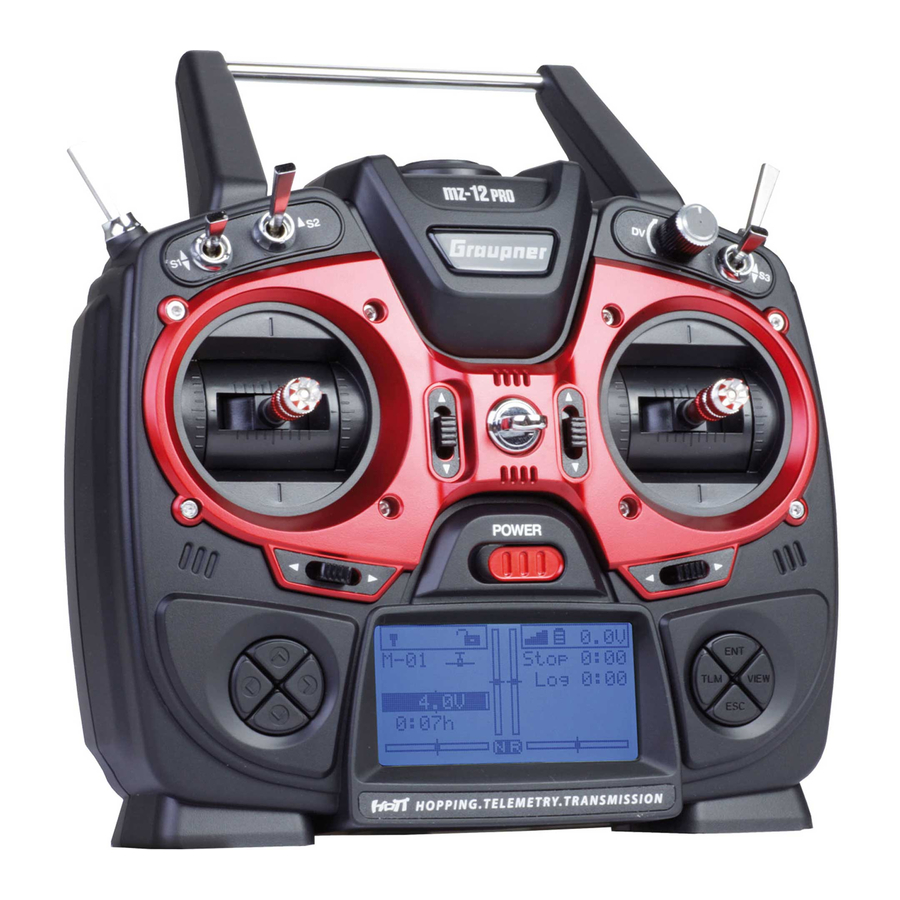
Description of the transmitter Control elements on the transmitter Integrated antenna Eyelet for neck strap Proportional dial DV 2 way switch SW 3 3 way switch SW 6 and 7 Right stick Right four way keys Trim On/off switch Left four way keys Left stick 3 way switch SW 4 and 5 2 way switch SW 1... - Page 12 Case screws Battery case cover 3,5 mm jack to connect earphones or a DSC cable. Data socket to connect a smart box and to update the transmitter Micro USB port, charge port, update port, joystick function 12 / 28 S1002.PRO_jh_V1...
-
Page 13: Connections And Fixtures
This type of connection should therefore only be used if you protect yourself from electrostatic discharge while operating the simulator by wearing a commercially available grounding armband. Graupner therefore strongly recommends only using wireless simulators. Data socket The lower pins are suitable for connection of a smart box or an exter- nal bluetooth module. -
Page 14: Display And Touchpad
Display and touchpad 5.1V 1:23 M-01 Stop GRAUBELE Flug 11:12 5.4V 1:23h nor mal 5.5V Model name Memory 1 ... 250 Model type display (plane/heli, copter, car, boat) Optical display of the trim position Flight chronometer in min:s (forward/reverse) Flight timer in min:s (forward/reverse) Battery voltage (when a determined threshold is trespassed a warn message is displayed, contemporary a warn signal is emitted). -
Page 15: Commissioning
Commissioning Settings by the first use Adjusting screw of the brake spring for throttle/brake stick Neutralizing screw Stick self centering force adjust screws Start display After the transmitter is switched on by fixed wing of type "Motor on C1 front/rear" the position of the output 1, so as in hely model the output 6 connected servo, will be verified. -
Page 16: Control Sticks Length Adjustment
During this waiting time you can also switch the RF module off by Please select RF on/off? pushing the or button of the left four-way button which move the black field, in this way the "ON" is shown normally and "OFF" is inverted represented. -
Page 17: Neutralizing The Control Sticks
Closing step by step: Check if the upper and the lower part of the transmitter housing are correctly coupled and the tiny cables are properly placed. Screw the housing screws in their original position. Connect the battery holder. Neutralizing the control sticks Both control sticks can be set from neutralizing to non-neutralizing. -
Page 18: General Commissioning
• Start the binding process in your transmitter in the main settings menu 4. If the binding process has been unsuccessful, repeat the process. Transmitter power supply The mz-12PRO HoTT transmitter is normally delivered with a rechargeable battery. Inserting the battery Note Pay attention when inserting the battery to the correct position and make sure the contacts are solid. - Page 19 The transmitter battery can be charged by the current supplied by the USB port (5 V/max. 0.5 A). The charging process is shown through the red lightning Graupner text. The indication quits when, with switched off transmitter, the battery is full.
-
Page 20: Low Voltage Warning
Low voltage warning The transmitter battery voltage should be monitored in the display GRAUBELE 0:00.0 during operation. In case the voltage drops under a preset threshold, B a t t . m u s t Flug 0:00.0 standard setting 3,6 V, an acoustic warning signal is emitted and in b e r e - «normal »... -
Page 21: Short-Cuts
VIEW button Pushing the four-way keys will cause a jump from the transmitter's base screen or from almost any menu position to the "Servo display" menu. TLM button Pushing the TLM key will cause a jump from the transmitter's base screen or from almost any menu position to the telemetry menu. -
Page 22: Function Field In The Display
Function field in the display Depending on the given menu, certain function fields will appear on the bottom display line. A marked function is activated by pushing the SET key. Function field: SET SEL STO SYM ASY SET (SET) Setting SEL (SELECT) Selection STO (STORE) -
Page 23: Servo Display
One after the other, put both sticks into each of their four possible –100 % limit positions without exerting force at the limit position and check +100 % if the value are between -100% and +100%. If you note that the sticks do not reach the desired values, move to the "Stick calibration"... - Page 24 Good to know! The count of the channels displayed in this menu refers to the 12 control channels available in this transmitter mz-12PRO HoTT. The number of usable channels depends on the type of receiver as well as the number of connected servos and may therefore be signifi- cantly less.The number of usable channels depends on the type of...
-
Page 25: Firmware Update
The current firmware version can be found on the Internet at www.graupner.de. Only operate your transmitter using the current software ver- sion. these information can also be found at: www.graupner.de => Service & Support => Update and revision history for GRAUPNER HoTT components. -
Page 26: Declaration Of Conformity
"Restoration" in the instructions provided in the software package. Declaration of conformity S.1002.PRO - mz-12PRO HoTT Graupner/SJ declares that the product is conform to EU norms. EMV 2004/108/EC: EN 301 489-1 V1.9.2 EN 301 489-17 V2.1.1... -
Page 27: Notes On Environmental Protection
The present construction or user manual is for informational pur- poses only and may be changed without prior notice. The current version can be found on the Internet at www.graupner.de on the relevant product page. In addition, the company Graupner/SJ has no responsibility or liability for any errors or inaccuracies that may appear in construction or operation manuals. - Page 28 FCC Statement 1. This device complies with Part 15 of the FCC Rules. Operation is subject to the following two conditions: (1) This device may not cause harmful interference. (2) This device must accept any interference received, including interference that may cause undesired operation. 2.
Need help?
Do you have a question about the mz-12PRO HoTT and is the answer not in the manual?
Questions and answers