
Subscribe to Our Youtube Channel
Related Manuals for GRAUPNER mz-10c


Summary of Contents for GRAUPNER mz-10c
- Page 1 MANUAL mz-10c HoTT 2.4 GHz transmitter for copters and drones No. S1001.G1 and S1001.G1.77 mz-10...
-
Page 2: Table Of Contents
Contents Contents ....................2 Introduction ..................4 Service Location ..................4 Intended Use ..................5 Target Group ..............5 Package Content ...................5 Technical Data ..................6 Symbols Explication ................7 Safety Notes ..................7 Transmitter Safety ............8 Battery Safety ............... 8 Transmitter Overview ................9 Transmitter Control Functions ........9 Digital Trim ............ - Page 3 Binding the Transmitter ........18 Performing a Range Test ........18 Range Warning ........... 18 Adjusting Tension and Centering ........ 19 Opening/Closing the Transmitter Housing ..19 Centering the Control Stick ........ 20 Break Spring and Ratchet ........21 Stick Centering Force .......... 21 Operation and Settings ...............
-
Page 4: Introduction
Introduction Thank you for purchasing the Graupner mz-10c Multirotor Radio. The mz- 10c has been specially designed to make all of your copter flying easy and fun. Setting up a new copter should not take more than 15 minutes before you can fly. -
Page 5: Intended Use
Read through this entire manual before you attempt to install or use the transmitter. Graupner continuously enhances its products and reserves the right to change its products, technology and equipment at any time and without prior notice. Target Group This product is not a toy. -
Page 6: Technical Data
Technical Data Transmitter mz-10C HoTT Frequency band 2.4000 to 2.4835 GHz Modulation FHSS Controller 16-bit Microcontroller Resolution 1024 Transmitting power 100 mW Model memory Trim control functions Temperature range 14°F to 131°F (-10°C to 55°C) Antenna Dipole Operating voltage 3.4 to 6V Power consumption approx. -
Page 7: Symbols Explication
Symbols Explication Always observe the information indicated by this warning icon, particularly those which are additionally marked with the following signal words: WARNING indicates the potential for serious injury. CAUTION indicates possibility of lighter injuries. This icon indicates information that may be helpful in diagnosing or troubleshooting, especially when accompanied by the following signal words: Note indicates potential malfunctions. -
Page 8: Transmitter Safety
Transmitter Safety WARNING Rotating propellers can cause injury. To make sure the connected motors cannot accidentally start when programming the transmitter, use the safety switch to turn the transmitter’s motor off, or detach the propellers. CAUTION Short-circuiting the transmitter sockets can create a fire hazard. Use only suitable connectors. -
Page 9: Transmitter Overview
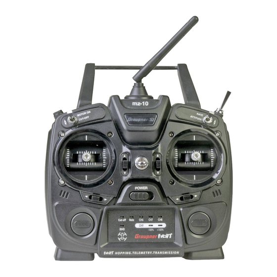
Transmitter Overview Transmitter Control Functions mz-10 Antenna with folding and swivel joint Neck strap eyelet 2 way switch (Attitude / Rate mode) 3 way switch (FLIP / OFF / LED) Right stick Arrow key (select video channel) Trims (active in Attitude mode only) On/off switch LED indicators panel 10 MODE key (BIND;... -
Page 10: Digital Trim
Digital Trim Digital trim with acoustic feedback The two sticks have digital trimming. Note The digital trim is only active in Attitude mode (switch 3) To trim your copter, briefly touch the trim in the opposite direction of where the correction needs to be made. For example, if the copter drifts to the right, add a few clicks of left trim. -
Page 11: Transmitter Back Side
Transmitter Back Side Case screws Battery case cover Data ports to connect: USB connector for updates, regional settings and control modes optional SMART BOX Bluetooth module AC adapter port for rechargeable batteries (not included) 11 / 33 S1001.G1 and S1001.G1.77-USA-V1.0... -
Page 12: Data Port
Data Port Connection options 1. To display telemetry data, receiver settings and telemetry/GR-18 flight controller PID settings, attach a SMART-BOX (No. 33700) to the data port. 2. To update transmitter software or firmware, insert the USB adapter into the data port. 3. -
Page 13: Transmitter First-Time Use
Transmitter First-Time Use Power Supply The mz-10c Multirotor transmitter comes with 4 non-rechargeable AA batteries. Installing the Batteries WARNING Never recharge alkaline batteries. Batteries may explode. Note Make sure to insert the batteries into the correct position for proper contact. -
Page 14: Using Rechargeable Batteries Option
Using Rechargeable Batteries Option The back side of the mz-10c is equipped with a charging port for recharging NiMH batteries (No. S8359). WARNING Follow all safety instructions included with the batteries! Charging Port Polarity Only use original Graupner charging cables. Charging cables sold by other manufacturers often have different polarities and can permanently damage your batteries or equipment. -
Page 15: Led Panel And Buttons
LED Panel and Buttons MODE button Press and hold while switching on the transmitter: Starts the firmware update Activates the Fail-safe setting Transmitter switched on: Binding transmitter and receiver Short push takes a snapshot through the camera (optional) Push for 2 seconds: select video channel (optional) CUT-OFF Red LED blinks: Motor/throttle cut-off is ON Red LED off: Motor/throttle cut-off is OFF... -
Page 16: Multirotor Installation
Verify that all propellers are removed from your multirotor. Graupner is not responsible or liable for any injuries sustained during the installation and setup of the mz-10C and GR-18C due to improper use or inattention to safety procedures. Find a proper location to mount the GR-18C receiver/controller, for example, towards the front of the multirotor right behind the FPV camera if you have one. -
Page 17: Before Flight Safety Checklist
Before Flight Safety Checklist Choose a wide open space such as a soccer or baseball field. Don’t fly in the vicinity of people, houses, your backyard or obstacles such as trees and electrical poles. Before attaching the battery, always make sure that the motor ON/OFF switch is on the OFF position and that your throttle stick is always at the bottom of the throw (towards user). -
Page 18: Binding
2 seconds Range Warning Note If a range test cannot be successfully performed, contact your nearest Graupner service center for additional support. CAUTION Never start a range test on the transmitter while the model is currently in operation! -
Page 19: Adjusting Tension And Centering
Adjusting Tension and Centering Brake spring and ratchet adjusting screws Centering lever Screw to convert from self-centering to non-self-centering Stick self-centering force adjusting screws Brake spring and ratchet Opening/Closing the Transmitter Housing The transmitter is pre-set at the factory for proper Region and Stick Mode and should not be opened except in the following cases: ♦... -
Page 20: Centering The Control Stick
CAUTION Never switch the transmitter on while the housing is open! Open step by step: 1. Switch the transmitter off before opening the housing. 2. Open the battery compartment. 3. Remove the battery box by lifting it gently at one side to release it from the Velcro tape. -
Page 21: Break Spring And Ratchet
Break Spring and Ratchet Adjust the tension force of the two outboard screws marked in the figure. The inboard screw adjusts the strength of the ratchet for the respective control stick. Note The right stick gimbal is specular to the left one. Stick Centering Force The sticks’... -
Page 22: Operation And Settings
The transmitter can be configured to support different country and stick mode (1-4) settings. For most regions the country setting GENERAL and MODE 2 is the default for proper operation of the mz-10c. DO NOT make any of the changes below unless absolutely required for proper operation of the mz-10C. -
Page 23: Stick Mode
Stick Mode There are four different options for assigning the stick functions: roll, nick, yaw and throttle/pitch. Modes are chosen depending on pilot preferences. Changing the stick mode Changing the mode step by step 1. Activate the transmitter programming mode. 2. -
Page 24: Fail Safe
Fail Safe The Fail Safe function determines receiver response in the event that transmitter communication is interrupted during flight. Note The standard setting, until a change occurs, is the central position. In case of interference: ♦ Maintain the current HOLD position. ♦... -
Page 25: Hold Mode
The transmitter is now in STICK MODE. Check the settings by switching off the transmitter. Correct or repeat the programming if the functions of the copter do not move to the desired position. HOLD Mode In case of transmission interruptions, all functions programmed to HOLD default to the last saved position. -
Page 26: Off Mode
OFF Mode In the event of a malfunction the OFF Mode allows the receiver to stop transmitting servo output control pulses. The receiver switches the pulse line OFF. To save the selection, press and hold the MODE button for 3-4 seconds. Release the button. -
Page 27: Switch Functions
Switch Functions Motor ON/OFF Function The motor stop function is active completely independently from the position of this switch, until after switching on the transmitter the throttle/pitch stick has not been brought at least once in the motor-OFF position. ATTENTION To prevent accidental motor starts and risk of accident, make it a habit to move the MOTOR OFF switch forward only during takeoff. - Page 28 28 / 33...
-
Page 29: Firmware Update
4. In the next step you will be asked be asked to switch the transmitter on and push the MODE button simultaneously on the mz-10c transmitter while you switch it on. Release the MODE button as soon as the transmitter has been recognized: “Found target device”... - Page 30 6. The end of the data transfer will be indicated by the update program. The transmitter indicates the end of the transfer trhough the power-on melody. 7. Switch off the transmitter and remove the USB connection from the PC. Your mz-10C is now updated with the latest software. 30 / 33...
-
Page 31: Declaration Of Conformity
Declaration of Conformity S1001.G1 mz-10c HoTT Graupner/SJ declares that the product is conform to EU norms. FCC ID: SNL-36204210 FCC ID: SNL-16006100 CL: 20961-36204210 CL: 20961-16006100 EMV 2004/108/EC: EN 301 489-1 V1.9.2 EN 301 489-17 V2.1.1 EN 62479:2010 LVD 2006/95/EC: EN 60950-1 + A11 + A1 + A12 + A2:2013 R&TTE 1999/5/EC:... -
Page 32: Disposal
Clean the product by lightly rubbing with a dry cloth. Do not use detergent! Warranty Certificate Graupner USA OPENHOBBY LLC at 3941 Park Drive Suite 20-571, El Dorado Hills, CA 95762 warranties this product from the date of purchase for a period of 24 months. - Page 33 Notes 33 / 33 S1001.G1 and S1001.G1.77-USA-V1.0...
Need help?
Do you have a question about the mz-10c and is the answer not in the manual?
Questions and answers