GRAUPNER mz-24 Pro Programming Manual
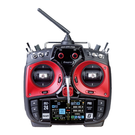
12 channel hott 2,4 ghz transmitter
Hide thumbs
Also See for mz-24 Pro:
- Manual (34 pages) ,
- Programming manual (241 pages) ,
- Programming manual (240 pages)

Subscribe to Our Youtube Channel
Related Manuals for GRAUPNER mz-24 Pro


Summary of Contents for GRAUPNER mz-24 Pro
- Page 1 Manual mz-24 Pro 12 channel HoTT 2,4 GHz transmitter No. S1006.PRO Part 2 Programming manual...
-
Page 2: Table Of Contents
Index General operating instructions Model type ............. 60 Swashplate mixer ..........172 E.P.A ............... 62 Swashplate limiter ..........173 REV/SUB ..............64 Heli mixer .............. 174 Throttle Cut ............. 66 Throttle mixer ............176 Transmitter setting ..........68 What is a mixer? ........... 132 Before use .............. -
Page 3: Before Use
If you experience any trouble during operation, take Telemetry data display .......... 225 Attention warns against the instructions to help or ask your dealer or Graupner potential damages to objects. Service Centre. Programming examples To make the research of important information eas-... -
Page 4: Starting Up The Transmitter
Theoretically, the Graupner-HoTT system allows more of the display it will appear the message: model memory has once been linked to a Graupner- than 200 models or remote-control systems to be op- HoTT receiver but is presently not linked. - Page 5 ... the currently active model memory is not linked to • When training, linking or adjusting the remote CAUTION SET any receiver. Tapping on the button you accede control, make sure that the transmitter anten- Never turn off the transmitter while oper- setting«, immediately the under-menu »Transmitter...
-
Page 6: Operating The Display
Operating the display The display is basically operated by touching the de- Touching one of the three gear icons identified with sired field with a finger or the provided stylus: "B", "F", and "S", special selection menus open on the bottom right from which you can switch to other sub-menus. - Page 7 ... and the display which can be accessed by tap- ping on "T" and detailed described from page displayed for graphic representation of the telemetry data e.g. so: Operating the displays...
-
Page 8: Warnings
Warnings If instead by switching the transmitter, there is already In the display of the mz-24 HoTT Pro transmitter ap- pear different warning windows. These can be divided a receiver bound to the model memory and inactive into two groups: Thr.POS warning, the transmitter will switch on and the RF module will also be active. - Page 9 "Acute warning" display At the same time, the display contrast is reduced to 05 to save power. You can open this display by touching mz in the mid- This warning can be kept from reappearing by touch- dle of the transmitter's basic display ... ing the ON ...
-
Page 10: Dsc Socket
Further information on the Smart Box and the Blue- connected to your simulator, the transmitter may be de- tooth module can be found in the main Graupner FS stroyed by electrostatic discharge. This type of connec- catalogue and on the Internet at www.graupner.de... -
Page 11: Ear Phones Port
These mes- found on the downloads page for the transmitter un- memory card is inserted, the transmitter cover can be sages are in German by default. Further information www.graupner. closed. can be found under "Announces" in the ""Teleme- Notice try""... -
Page 12: Mini-Usb Connection
In order to be aware of important software updates, you updates as well as the date and time setting from a should therefore register at https://www.graupner.de/ desktop or laptop with one of the Windows operating de/service/produktregistrierung.aspx. This will allow you systems (XP, Vista, 7 ... 10): to automatically receive updates by e-mail. - Page 13 Personal notes...
-
Page 14: Starting Up The Receiver
If the receiver temperature falls below a threshold description included in the package of the receiver, to Graupner HoTT receiver must be "bound" to its model which can be set in the receiver (-10°C by default) or indicate that your transmitter/receiver system is ready memory in its Graupner HoTT transmitter. -
Page 15: Installing The Receiver
Installing the receiver Installing the receiver antennas Channel mapping Whatever Graupner receiver system you use, the In case of single antenna, the orientation is not crucial. The function of each channel is determined by the procedure is the same. -
Page 16: Installation Notices
Graupner|SJ GmbH for suitability, functioning and safe- ty. If this is done, Graupner|SJ GmbH will assume re- sponsibility for the product. However, Graupner|SJ GmbH assumes no liability for •... - Page 17 Never endanger people that we recommend. Always use matching, or animals. Never fly close to power original Graupner plug-in connections of the lines. In addition, never operate your same design and material. model close to locks and open nauti- cal traffic.
- Page 18 "Charge the battery!" appears in the Only use original Graupner rechargeable batteries! display, and an acoustic warning sounds. Regularly check the battery charge, especially of the receiver battery. Do not wait until the movements of the rudder are noticeably slower.
- Page 19 Personal notes...
- Page 20 You should not only therefore choose a power supply in the main Graupner FS catalogue as well as on the that does not fail under a permanent high load and Internet at www.graupner.de.
- Page 21 "growl" when operated with a 5-pack. cell LiPo battery packs does not pose any problems Notice to Graupner HoTT receivers or the servos, speed con- You should therefore note the specifications for trollers, gyros, etc. which are approved for operation your servo before ...
- Page 22 Charging Graupner LiPo/LiIo batteries ies is 0... +50°C. Disconnect the battery, and place it on a non-flam- • Since Graupner|SJ GmbH is unable to monitor • Batteries as well as individual cells are not toys mable surface (such as concrete) until it cools whether the batteries are correctly charged and and must be kept ...
- Page 23 This causes a loss of electro- by means of the usual balancer plug-in connec- lyte, gas formation or even explosions. Graupner Direct soldering on the battery cells is impermis- tion.
-
Page 24: Definition Of Terms
Definition of terms Control function, control, function input, control channel, mixer, switch, control and logical switch To make it easier to use the Part 2 of the manual, we • The two side proportional rotary controls SL1 and This signal is only influenced by the settings made in offer a few definitions of terms that appear repeatedly SL2 mounted on the bottom. - Page 25 With these program switches, all you have to do is specify the switching point along the control path in the direction of switching. More detailed information are easily available in the paragraph "Controls and switches assignment". Logical switch Through this option two switches, controls and/or logical switches or the favorite combination of them, can be interconnected in an "AND"...
-
Page 26: Control And Switch Assignment
Control and switch assignment Basic procedure In many places in the program, you can actuate a The following window appears in the display af- touch control function with a freely selectable control (ST 1 ter touching the corresponding button, such as NONE ... - Page 27 Assigning logical switch or control • Switch assignment The places in the program where a switch, a logical control or switch can be assigned are marked with "CTL". So as for example as marked with a red cir- cle in the penultimate line of the following picture of the Dual Rate / Expo displays: Thus completes the assignation of the switch for It has to be logically matched with the other switch...
- Page 28 Canceling the switch assignment Notice Notice After the switching assignment has been activat- In this case, be sure to specify a switching po- Therefore do not forget to program the related ed as described at the beginning of this section, sition that is not "000".
- Page 29 • Extend the landing flaps and retrim the elevator while approaching a landing once the throttle con- trol stick is moved beyond the switching point. • Turn the stop watch on and off to measure the op- erating time of electric motors. •...
-
Page 30: Receiver Configuration Vehicles, Boats And Copters
Receiver configuration Vehicles, boats and copters All of the relevant menus for the previously mentioned model types are identified in the next section with at least one of these three model characterizing "col- Also for copters there are basically four different ways ored"... -
Page 31: Helicopter Models
In comparison to the receiver configuration of ... with 1 to 3 swashplate servos tion with the symbol that characterizes this model some older Graupner/JR transmitters, servo type... connection 1 (pitch servo) and servo connection 6 (throttle servo) have been switched. The servos must be connected to the receiver outputs as depicted on the right. -
Page 32: Fixed-Wing Models
Motor-powered airplanes and glider models All of the relevant menus for motor-powered airplanes Fixed-wing models with and without a motor with Delta/flying wing models with and without a up to 4 ailerons and up to 4 flaps ... motor with up to 4 ailerons/elevators and 4 flap/ or glider models are identified in the next section with elevator servos at least one of these two model types characterizing... - Page 33 Due to the different installation of the servos and rud- der linkages, the operating direction for certain servos can be reversed. The following table offers assistance in this regard. Servo with wrong Model direction of rota- Solution type tion V-Tail Reverse rudder and Invert the servos 3 elevator...
- Page 34 Program description As already mentioned in section Operating the dis- "B“ ("green“ basis menu) "F" ("blue" function menu) plays, you can touch one of the four gear icons at the Touch the gear icon labeled "F" with a finger or with bottom right of the basic display identified with "B", the provided stylus: "F", "S"...
- Page 35 Name Menu Page Name Menu Page Name Menu Page Phase "Phase setting" Phase "Phase setting" Phase "Phase setting" D/R,EXP "Dual rate, Expo" D/R,EXP "Dual rate, Expo" D/R,EXP "Dual rate, Expo" PIT.CRV "Pitch curve" THR.CRV "Throttle curve" THR.CRV "Throttle curve"* THR.CRV "Throttle curve" Idle LOW "Idle setting"* Prog.MIX...
- Page 36 "S" ("purple“ system menu) "T" ("Telemetry display“) Touch the gear icon labeled with "T" at the bottom right with a finger or with the provided stylus: The display switches from the basic display to a dis- Touch the gear icon labeled "S" with a finger or with play of the telemetry data such as: the provided stylus: In this menu exclusively transmitter specific set-...
- Page 37 Personal notes...
-
Page 38: Model Selection
Model selection Edit model memories 1 … 30 Switch your receiver system and the RF module of x" value field your transmitter off. Then touch the "M line in the left side of the display with a finger or the provided stylus in the basic transmitter display of the transmitter: Touch... -
Page 39: Hott Synchronization Methods Setting
WITHOUT "G" on the right near the button = memory specific bound WITH "G" on the right near the button = transmitter spe- Touch cific (global) bound In the following representation the model memories 1, 2 and 3 are left as example on memory specific Now tap on the model type icon, ... - Page 40 CAUTION A receiver system, switched on acci- dentally after a model memory change, reacts to every control movements of the model memory bound in global mode as soon as a valid signal is emitted from "its" transmitter. If you want to switch a model memory, which is actu- •...
- Page 41 Touch … and then touch NO to terminate the process or So as it happens when you switch the transmitter … or by touching the related BACK button until YES to switch the model … on, you now have the option of waiting a few sec- you will be brought directly to the base display of onds until the display disappears automatically or the transmitter.
-
Page 42: Model Name
"Model name" In the following sub-menus, the options to configure To transfer the model name into the model memory, the required options will be proposed according to the touch the red button = [ENTER] at the bottom right: Switch between uppercase and lowercase and vice model type previously selected. - Page 43 "Model type" After you select a wing type, the following display ap- pears... Since at this juncture we want to program an "air- plane with electric drive", touch the selection field "Tail type" "MOT(motor model)": …, in which you can specify the type of your tail: Touch …, which you can leave to go to the base menu by touching the...
-
Page 44: Entering The Basic Settings Of A New Model With An Assistant
Entering the basic settings of a new model with "Model name" an assistant The previous section described the basic manual programming of a fixed-wing model. In the following, the assistant-controlled programming of a helicopter model will be described. As the manual programming, also the assisted programming follows always a pre- defined program procedure. - Page 45 "Model type" systems, the menu item "Swash", page , normally does not appear on the multifunction menu.) Since at this juncture we want to program a "helicop- ter model", touch the Heli button: • "2 Servo" To transfer the model name into the model memory, Touch touch the red button = ...
- Page 46 • "3Sv (2Nick)" "REV/SUB" (Servo reverse/Servo sub trim) Notices • The possibility to reverse the direction of the servos connected to the output 6 (C6) in a helicopter model and the output 1 (C1) in the other types is only offered to match with the different building cases.
- Page 47 "E.P.A." (Servo travel/limit) Conversely, the effect of the control around neutral position increases for values less than 0% and de- creases in the direction of the full deflection. The pro- gression can be set from -100% to +100%; 0% cor- responds to the normal linear control characteristic.
- Page 48 Basic operating steps • Button ST OFF ST ON Touch this button to turn the graphic and nu- meric display of the control stick position on Touch Touch and off, for example: Analogous to the previously described displays, touch After tapping on this button it will appear a safe- the corresponding option field to change a current ty query: value, and raise or lower the value by touching the...
- Page 49 Between the two endpoints "L" and "H", up to Once the support point number appears along Touch the X-axis button again to deactivate 5 additional support points can be set, and the with the associated value in the line "POINT" the function.
- Page 50 • TRIM button Remember that the percentages in the "IN"(put) The mz-24 HoTT Pro transmitters has a func- and "OUT"(put) line always refer to the momen- tion that is integrated in the helicopter program tary position of the control stick and not to the for trimming up to six support points of the position of the point.
- Page 51 • "PHASE" column If you want to, specify in the right "PHASE" column the programmed phases in which the governor should be active. In the value field, in the example, "1 (normal)", the num- ber refers to the phase number that can be found in the sub-menu "PHASE".
- Page 52 Notice "Throttle curve" Notice The settings that appear in this display af- The associated controller does not have any ef- The throttle curve can be specified by up to 7 points, fect the same records as those at a com- fect if an undefined point is selected (in the basic the so-called support points, along the entire control parable location in the "TRIM"...
- Page 53 7 in the button in the "Governor ACR" line. The display Graupner remote-control system. The gyro sup- switches from "OFF" to "ON" and vice versa, for Based on these phase specific settings (offset) the...
- Page 54 IMP.M (import from SD card) With the ""Throttle Cut"*" option in the Base menu, Once a memory card is in an operational transmitter, there is an alternative emergency off function. a blue memory card icon appears at the top right of the basic display: Touch the ...
- Page 55 changes accordingly and on the right near "ORIGIN" Once the process is completed, all the warning mes- appears the number of the memory to import in red sages will disappear, and the display returns to the list characters: of models and the transmitter: Then switch to the display of the data model saved on the SD card by touching the IMP.M ...
- Page 56 EXP.M (Export to SD card) Select the desired model memory, as for example the model memory 02, from the list offered in the "model Use this option to export models saved in the trans- sel." display. Tap on the field with the selected model mitter to a memory card inserted into the transmitter's name.
- Page 57 RES (delete model) In the "Model Sel" sub-menu described here... Touch NO to terminate the action and return to the If you have initialized not a "different" but the actually start page. After tapping on YES … in use model memory, after the end of the initialization two note windows will appear: …...
- Page 58 CPY (copy model model) In the "Model Sel" sub-menu described here... Touch Touch Additional information and buttons appear at the bot- … after a short while the message "Please Wait!" ap- tom right. pears … … using the CPY button at the right edge of the dis- play, you can copy an assigned model memory to any other model memory.
- Page 59 Touch Base menu - Model selection...
-
Page 60: Model Type
Model type Change the model type Switch your receiver system and the RF module of In the delivered form the transmitter the model selec- your transmitter off. In the basic transmitter display, tion display looks for example like this: use your finger or the provided stylus to touch the gear icon labeled "B"... - Page 61 The entire process is concluded by touching the ENT button at the lower right side of the display which re- sumes all the selected options, for example: Touch ... etc. For the remainder of the process, you only need to use the assistant as described in the men- tioned section until all the basic settings of the newly selected model type are entered.
-
Page 62: E.p.a
E.P.A E.P.A. Setting In the basic transmitter display, use your finger or the provided stylus to touch the gear icon labeled "B": In order to reach control channels with numbers higher than CH5, touch NEXT [change page] at the top right Touch of the display. - Page 63 Notice In contrast to the "CTL Set" sub-menu, all the settings of this sub-menu refer to the relevant servo independent of where the control signal for the servo comes from , i.e., either directly from the con- trol element or from mix functions. Example The rudder servo of a model is directly controlled by the rudder control stick and also through an accessory "Ai-...
-
Page 64: Rev/Sub
REV/SUB Setting of the servo direction and neutral position In the basic transmitter display, use your finger or the Servo direction and neutral position 1. Setting the servo direction provided stylus to touch the gear icon labeled "B": With this option, the direction of servo rotation is adapted to the specifics in the particular model so that, when the control linkages and articulations are installed, the servo's rotational direction does... - Page 65 Notice Notice To recall the graphic display of the servo travels of the "Servo" menu (servo monitor) and to activate In no case you should use the possibility of the Move the trim control into the middle position "Servo test" function integrated in this display servo reverse of the channel 6 for helicopters and before changing the middle values.
-
Page 66: Throttle Cut
Throttle Cut Switchable throttle cut or motor limiter "SET" line and needs to be determined through ex- perimentation. The speed controller or the throttle servo only as- This sub-menu is not shown in model type "glider with- • In this motor OFF position, the speed controller or sumes the set position if a freely selectable switch has out motor". - Page 67 Set a value with – on the right to the outside which allows the motor or engine to run affordable at the desired idle speed or which for example switches definitely the engine or motor "off": The adjustment range is ±150%. To recall the graphic display of the servo travels of the "Servo"...
-
Page 68: Transmitter Setting
A receiver system, switched on acci- Graupner HoTT receiver must first be "bound" to dentally after a model memory change, at least one model memory in "its" Graupner HoTT reacts to every control movements of transmitter. This process is generally called "binding"... - Page 69 Binding several receivers per model • To RX2 can only be bound a receiver if there is al- If desired, several receivers per model can be bound. ready a bound receiver on RX1 . In the related programs of the mz-24 HoTT Pro re- ceivers, you can directly manage up to two receivers •...
- Page 70 the receiver. As long as the LED is dark, the receiv- • If there is no other reaction than a "beep", the RF er is in binding mode. module is switched off. Switch the RF module on and repeat the process. As described above, within this 3 second win- dow, start binding the receiver to the current mod- •...
- Page 71 100 m. two options. Perform the range test for the Graupner-HoTT system Alternatively it is also possible to tap on the RF switch according to the following instructions. It is useful to symbol in the basic menu of the transmitter to recall a Assigning one channel to two receivers...
- Page 72 At the same time, 1 … 9, and with "PPM24", the control channels are 1 the illuminated company name Graupner below … 12. the two middle proportional dials starts to flash. Base menu - Transmitter setting...
- Page 73 AUTOLOG Touch the OFF button at the bottom right of the dis- play while RF module is switched off … Touch Touch ... to switch the automatic saving of the logging data or vice versa: As soon as you switch the RF transmission on, the log data start to be saved in the memory card inserted in the memory card slot and it will stop as soon as the transmitter or the RF module are switched off.
-
Page 74: Timers
Timers Setting TIMER 1 and TIMER 2 as well as the date and time The basic transmitter display comes with four timers Acoustic signal sequence (see the display below). Next to the transmitter oper- 20 s before zero: 2 beeps ating time and the model time on the left side of the Single beep every 2 seconds display, there is an "upper"... - Page 75 Repeatedly touched the + or – - button on the right edge of the display, or hold down the relevant but- ton until your desired time is displayed between 00:00 and a maximum of 59:59, for example: Notice Alternately, a timer can be switched beforehand from In both cases by stopping the "Timer 1"...
- Page 76 "START SW" (start switch) In this line you can assign to "Timer 1" or "Timer 2", as detailed described in the section "Control and switch Touch assignment", a timer to start the selected timer. Touch "STOP SW" (stop switch) In this line you can assign to "Timer 1", as detailed described in the section "Control and switch assign- ment", a timer to stop the selected timer.
- Page 77 "LAP List" Touch the button to clear in both cases the lap Date and time times: Tapping on the >> button … On the third display page of the "Timer" menu, you can enter or change the date and time. By tapping on the model timer display in the basic dis- play of the transmitter you can also directly recall this Touch display.
- Page 78 All value field are black, and the current date and time have been transferred to the memory. As soon as the transmitter is connected to the PC, the date and time can also be updated with the aid of "Firm- Touch ware_Upgrade_grStudio V4.x".
- Page 79 Personal notes...
-
Page 80: Fail Safe
Fail Safe What to do in case of a malfunction In the basic transmitter display, use your finger or the Therefore the "Switch-on fail safe" function ensures Programming provided stylus to touch the gear icon labeled "B": that as far, after switching the receiver system on, no To switch between "HOLD"... - Page 81 Notice After having set the fail-safe positions so as the By tapping on the needed button in the "MODE" proper delays, the settings saved on the trans- column the stored fail safe position can be recalled and mitter must be transmitted to the receiver. Other- changed as described.
-
Page 82: Trim Settings
Trim settings Trimming settings In the basic transmitter display, use your finger or the Phase depending settings ... sets the trim of the control function 2 ... 4 from provided stylus to touch the gear icon labeled "B": phase influencing (CO (global)) to phase specific (SE The here mentioned sub-menu offers the possibility to (phase)) and vice versa. - Page 83 Set the desired value with the + – button at the "SET" line (saving trimming positions) right edge, for example: This option allows you to optionally save the current position of the four digital trimmings so that they can be returned to the visual middle position. After a mod- el memory is changed or after long periods between flights, the last safe trimming positions are available in the middle positions of the respective trimming dis-...
- Page 84 Deleting saved trimming positions Digital Trim 1 and 2 Touch the value field with the trimming value you want Independent from the above described settings of the to delete, for example: trim control 1 ... 4, you can assign the INC/DEC but- tons "DT1"...
- Page 85 • EACH activation of the AUTO TRIM switch acts cumulatively, that is why for safety rea- The same display can be reached at any time from the sons is strictly recommended to use the basic display of the mz-24 HoTT Pro, by tapping on switch only once and to deactivate it after the one of both middle bar graphics: "AUTO TRIM flight"...
-
Page 86: Servo Monitor
Servo monitor Display of servo positions and servo test function In the basic transmitter display, use your finger or the As soon as you will have defined one or many oth- Helicopter models provided stylus to touch the gear icon labeled "B": er phases in the "PHASE"... - Page 87 puts made in the "Transmitter output" sub- Servo test menu, or in the "Receiver output " sub-menu setting" sub-menu. Notice of the "Transmitter Only start a servo test in a model memory creat- • The count of the channels displayed in this ed for this purpose without any mixer.
- Page 88 Touch NO to terminate the procedure. Touch to start the servo test function. This func- tion automatically controls the servos operating under the assumption that the associated controls (starting from the neutral position) will be simultaneously and continuously moved back and forth between -100% and +100% during the set period.
- Page 89 Personal notes...
-
Page 90: Base Menu - Control/Switch Setting
Base menu - Control/switch setting Control and switch assignment In the basic transmitter display, use your finger or the In contrast to the two control sticks that immediately • In contrast to setting servo travel, setting the act on the servos connected to receiver outputs 1 ... 4 provided stylus to touch the gear icon labeled "B": control travel affects all outgoing mixing and with a newly initialized model memory and for an heli-... - Page 91 "CTL/Set" column (control/switch) Deleting controls or switches Touch the value field of the assignment to be deleted, Assigning switch or control for example: To assign a control element tap on the value field in the line of the desired control channel, for example input 6 in the second display page of this sub-menu: Touch Touch...
- Page 92 Use the same procedure for the other settings. "OFFSET" column Touch the button to reset a changed value in the blue (and hence active) field to the default value. Change the center of each control element, i.e., its Notices Use the same procedure for the other settings. zero point (if desired with reference to a specific •...
- Page 93 Notice Set a symmetrical delay for the transmitter-side control signal with buttons with the standard la- beling 0.0s . A delay which is set here affects the servo that has the number of the delayed receiver con- nection as well as all servos controlled by the control element assigned to control function X.
-
Page 94: Throttle Limit Function
Throttle limit function After the initialization of a new model memory with With this setting and the assignation of a control to The set value on the (right) plus side of the "Travel" the model type "helicopter" in the transmitter mz-24 the input 12, it is unnecessary to program two phases column of the function menu, therefore has to be large HoTT Pro the input "12"... - Page 95 While the gas limiter is closed, adjust the carburetor linkage so that the carburetor is completely closed. Make sure that the throttle servo does not mechan- ically over-travel in the two extreme positions (full throttle/motor OFF). To conclude this basic setting, match the setting range of idle trimming with point "L"...
-
Page 96: Transmitter Output
1 tle servo have been changed in comparison to previ- to 12 in the program of the mz-24 HoTT pro transmit- ous Graupner/JR transmitters. The throttle servo is as- ter according to your preference: Set the desired value with the + ... - Page 97 In addition, several receiver outputs can be assigned the same control function. For the sake of clarity, it is strongly recommended to only use one of the two op- tions. Base menu - Transmitter output...
-
Page 98: Telemetry
After the product has been registered at https://www. called "slave mode"! the mz-24 HoTT Pro transmitter, the control graupner.de/de/service/produktregistrierung.aspx, you • The exchange of telemetry data between channels of these transmitters can be distrib- will automatically be notified of updates by e-mail. - Page 99 • The model or sensors may only be Telemetry If you have bound a receiver as RX1 or also as RX2 in programmed when the model is on the ctl", then you can declare one of the sub-menu "TX The menus that fall under the generic term of "Telem- ground.
- Page 100 Specifically if there is the possibility of reciprocal interfe- • If, however, you have opened one of the sub- rence of the back-channels, as for example in a camera menus described below and this is unex- drone with separate camera and copter control or a to- pectedly replaced by, as the selection menu wing model for model-parachute.
- Page 101 SETTING & DATA VIEW On the first page of the display with the header … Consequently, the reception shown in dBm in the dis- L PACK Shows the longest time in millise- play is generally negative. The higher the number after TIME conds in which data packages were RX DATAVIEW...
- Page 102 R-TEM. (receiver temperature) CAUTION Value Explanation Possible set- Always keep an eye on the receiver's op- tings Make sure that the temperature of your receiver re- erating voltage. If it is too low, do not op- mains within the permissible range under all flight Vx.xx Firmware version None...
- Page 103 An adjustment within 30 … 150% is performed sepa- rately for both directions. Factory setting: 150%. PERIOD (cycle time) In this line, specify the periods for the individual chan- nel pulses. This setting is transferred for all control channels. When using digital servos, you can set a cycle time Select the desired receiver servo connection (such as Now move the corresponding control, control stick of 10 ms.
- Page 104 It is therefore recommendable to at least program "mo- In this case, remember that only the receivers select- INPUT CH Input channel 1 … max. 12 tor off" to prevent such risks. If necessary, consult a ed in the "RECEIVER SELECT" line can be addressed (control channel competent pilot to find a recommendable setting for by the "Telemetry"...
- Page 105 The setting programmed under "MODE" always refers The setting is made in 10-μs increments, for example: FAIL SAFE ALL (global fail safe setting) to the channel set in the line OUTPUT CH. This sub-menu allows you to easily determine the fail The factory setting for all servos is "HOLD".
- Page 106 RX FREE MIXER Turn off the transmitter and check the fail safe posi- … then INPUT CH 04 determines the fail safe behav- tions by checking the servo travel. ior of these three servos connected to control channel Value Explanation Possible set- 4 fully independent of the settings of the respective "Fail safe"...
- Page 107 MIXER RX WING MIXER TAIL TYPE (tail type) If the rudder travel is not as desired, observe these Notices. Up to five mixers can be programmed. In the "MIXER" Notice line, select one of mixers 1 … 5. RX CURVE The following model types are also available in The following settings in this display only relate to the With the RX CURVE function, you can administer con- the base menu of a model and should preferably...
- Page 108 Generally, a nonlinear control function is used for the The servo reacts strongly to control stick move- … alternatively not only the adapter cable (No. 7168.6S) for updating the receiver but also a teleme- aileron (channel 2), elevator (channel 3) and rudder ment around the neutral position.
- Page 109 RX SERVO TEST ALARM Alarm threshold -20 … +10 °C With the RX SERVO TEST function, you can test the TEMP– when the receiver factory setting: servos connected to the currently active receiver: temperature is too -10 °C CH OUTPUT Channel sequen- ONCE, SAME, TYPE...
- Page 110 When the voltage falls below the set alarm thresh- CH OUTPUT TYPE (connection type) This is recommended for digital servos when sev- old, a warning tone sounds, and "VOLT.E" appears in eral servos are used for a single function (such as In this line, select the type of servo control or alter- white at the top right in all "RX..."...
- Page 111 Internet at www. vant tests be performed before starting the graupner.de. model. By means of this connection, all of the channels This receiver configuration is recommendable selected in the "CH OUT TYPE" line of the HoTT...
- Page 112 • SUMD (digital sum signal) A HoTT receiver configured as SUMD as described earlier always generates a digital aggregate signal from the control signals of a selectable number of its controls channels, see more about on in the SUMO section, and forwards this to servo connec- tion 8 in the GR-16 and GR-24 receivers.
- Page 113 SENSOR Display of active/inactive sensors SETTINGS, DISPLAYS for sensor(s) Touch the corresponding button ... If one or more sensors are connected to a receiver and a telemetry link exists with this receiver, you can retrieve the display of any sensor and change its set- tings after the display "RX SERVO TEST"...
- Page 114 Display of RF status Touch the corresponding button ... Value Explanation Quality expressed as a percentage of the signal packages from the receiver arriving at the transmitter Quality expressed as a percentage of the signal packages from the transmitter arriving at the receiver Touch Level in dBm expressed as the percen- tage of the receiver signal arriving at the...
- Page 115 Personal notes...
- Page 116 VOICE TRIGGER Touch the corresponding button ... • As soon as the transmitter and/or the receiver have been switched on, the system starts the research of the connected sensors. A conversion in the val- ue field V-TON is only possible after the 30 sec- onds which are normally required to complete the research.
- Page 117 • automatic sequential TRANSMITTER RECEIVER As long as the switches assigned to the line "RE- After tapping on the desired button ... After tapping on the desired button ... PEAT" and "TRIGGER" are switched on, ... Touch Touch … to open the selected sub-menu: …...
-
Page 118: Announces
Announce Setting individual announces In the basic transmitter display, use your finger or the Phase depending settings "PHASE" column provided stylus to touch the gear icon labeled "B": In this column you can change between "CO" (glob- The here mentioned sub-menu offers the possibility al), which means model memory specific, and "SE"... -
Page 119: Function Menu
Common function menus Select through the + – buttons out on the right the desired voice file, for example: With each switch position and with other lines you can proceed in the same way. Touch the button to reset a changed value in the blue (and hence active) field to the default value. -
Page 120: Phase
Phase Setting up phases In the basic transmitter display, use your finger or the Furthermore, it should be noted that the flight phases provided stylus to touch the gear icon labeled "F": have priority, which should be taken into account, in particular, in the allocation of individual switches. - Page 121 Setting up phases • "PHASE" column As long as the actual settings belong to Phases, Touch they are referred to "Phase 1". To set up the first real phase, touch the desired value field in the "PHASE" column such as "PHASE 2" (or higher): In the "SLOW"...
- Page 122 • DEL button (delete) A blue, set-up phase that is therefore active can be deleted or deactivated by touching the DEL [de- lete] button at the right of the display with your fin- ger or the provided stylus, for example: Touch Touch ...
- Page 123 Attention In the "AUTOROT" phase you should always leave the standard 0.0s switch time, so that in case of necessity you can switch to this phase without delay. … and assign a switch or control switch as de- After you have finished making your settings, touch scribed in section Control and switch assignment.
-
Page 124: D/R,Exp
D/R,EXP Influence of the control attitude of the control functions 2, 3 and 4 In the basic transmitter display, use your finger or the provided stylus to touch the gear icon labeled "F": Touch An individual characteristic curve for control function 1 The display switches to the blue function menu. - Page 125 The actual rudder control is nonlinear since the rudder deflection from the servo linkage becomes increas- ingly smaller as the angle of rotation of the connecting pulley or cantilever increases. When EXP values are greater than 0%, this effect can be counteracted so that the angle of rotation increases disproportionately as the control stick deflection increases.
- Page 126 The dual rate curve is simultaneously displayed in the graph. Touch Touch the button to reset a changed value in the blue (and hence active) field to the default value. Attention For safety reasons, the dual rate value should not fall below 20%. The button color of both value fields changes from Set the desired value with the + ...
- Page 127 Combining dual rate and exponential values If you enter a value for both the dual rate and expo- nential function, the effects of the two functions over- lap as follows: After you have finished making your settings, touch BACK button at the top left of the display to return to the menu selection.
-
Page 128: Thr.crv
THR.CRV Setting the control characteristic of the Throttle control stick Phase depending settings The momentary control stick position is also displayed numerically in the line "IN"(put) (-100 % to +100 %). The here mentioned sub-menu offers the possibility Then move the throttle to one of the two end positions of phase specific settings. - Page 129 The graphic display makes it much easier to specify Between the two endpoints "L" and "H", up to 5 the support points and their adjustment. It is, how- additional support points can be set, and the dis- ever, recommendable to start with just a few support tance between neighboring support points may points.
- Page 130 The sequence in which the up to 5 points between Changing the support point value You can then move an active (red) point to the top + – the end points "L" and "H" are generated does not with the button, and to the bottom with the •...
- Page 131 Attention The curves shown here are only for demon- stration purposes and do not represent actual throttle curves. After you have finished making your settings, touch BACK button at the top left of the display to return to the menu selection. Function menu | general - Curve CH 1...
-
Page 132: Basic Functions
What is a mixer? Basic functions In many models, it is frequently desirable to mix func- More information about this subject can be found on tions within the model, for example to couple ailerons the relevant page on "free mixers". and rudders, or to couple two servos when you want two rudders with the same function to be controlled by a single servo. -
Page 133: General Information On Programmable Mixers
General information on programmable mixers This manual has described numerous preprogrammed To be safe, a corresponding travel limit should there- coupling functions. The basic meaning of mixers and fore be set in the "E.P.A" sub-menu. their functions are explained on the page to the left. In the program, a free mixer is initially always blocked The following offers information on "free mixers". -
Page 134: Free Mixer
Free mixers free programmable linear and curve mixers In the basic transmitter display, use your finger or the Page change provided stylus to touch the gear icon labeled "F": NEXT Press the button at the top right edge of the display to switch the rotation procedure in the selec- tion page between linear mixer 1 ... - Page 135 Mixers in which the mixer input is set to be the same as the mixer output (such as CH1 >> CH1) allow you to achieve special effects in connection with the Touch option of turning free mixers on and off as desired. Touch Touch the button to reset a changed value in the...
- Page 136 Activating and deactivating mixers To activate or deactivate a mixer set up as described above, touch the value field of the mixer to be activat- ed or deactivated in the "ACT" column, for example: Touch In this case as well, touch the "MST" or "SLV" button Touch of the mixer to be deleted.
- Page 137 "TRIM" line The color of the field switches from black to blue: As standard also the digital trim of each one of the control functions 1 ... 4 act on the mixer input. The same is for the control functions 5 ... 12, in case you have assigned one of those functions to one of the INC/DEC buttons.
- Page 138 • Offset X Touch the button to reset a changed value in the blue (and hence active) field to the default val- A value unequal to "000%" entered in the "Offset X" line causes the offset to shift horizontally by a maximum of ±100%.
- Page 139 … and assign a switch or control switch as described To show this line, touch the ST OFF button at the in section Control and switch assignment: bottom left: Touch Touch … a red dot appears at the interface between the two lines.
- Page 140 Deleting a support point In order to delete the set support points 1 to 5, move the green line with the associated control element next to the relevant support point. Once the support point number appears along with the associated val- ue in the line "POINT"...
-
Page 141: Trainer
Trainer Connection between two transmitters with a DSC cable Notice Select by touching the control function inputs 1 to 12 The mz-24 HoTT Pro transmitter comes standard with a DSC socket in the rear of the transmitter. This to be transferred to the PUPIL, for example: The above figure shows the initial status of this can be used to connect flight simulators but also to sub-menu: The PUPIL control has not been re-... - Page 142 Almost any transmitter from the past and current connected during the switch assignment. At the same Graupner product line with at least 4 control functions time, a warning message flashes every second at the can be used as the PUPIL transmitter. The PUPIL...
- Page 143 DSC middle position after transferring control func- module - order No. 3290.24) to a Graupner tions to the PUPIL transmitter. PUPIL transmitter with a PUPIL socket for • Independent of the type of RF link of the...
-
Page 144: Connecting Scheme
Connecting scheme The connecting schemes on this page constitute the transmitter combinations possible at the time at which this manual was created. Pupil transmitter mz-24 HoTT Pro Teacher transmitter mz-24 HoTT Pro DSC cable Trainer cable No. 4179.1 No. 4179.1 Trainer cable Trainer cable No. -
Page 145: Wireless Hott System
It does not matter which specific are as- position after transferring control functions to the signed to the inputs to be transferred to the PU- With Graupner HoTT transmitters of the series " ", PUPIL transmitter. Set" PIL. They can only be assigned in the "CTL... - Page 146 Observe the standard conventions in the model types "motor airplane" and "glider" so as in the model type "helicopter" when assigning control functions: Channel Function Touch Motor/airbrake or pitch Since at this early point in the trainer system pro- Once this process has concluded, "ON" appears in Aileron or Roll gramming an operable PUPIL transmitter will not be both displays instead of "CHK":...
- Page 147 During … Tapping on the ON button you confirm that the train- OFF er mode is active. Tapping on stops the training training mode. … the teacher and pupil can maintain a comfortable distance. The "earshot" distance (a maximum of 50 m) should not be exceeded, and no one should be be- tween the teacher and pupil since this would reduce the range of the feedback channel used to connect...
-
Page 148: Logical Switch
Logical switch Programming the logical switch In the basic transmitter display, use your finger or the Programming "AND" / "OR" provided stylus to touch the gear icon labeled "F": The standard switch connection "AND", and vice ver- The assignation of a required switch for a logical con- sa, is set by tapping the related value field, for exam- nection is performed as usually in both value fields ple:... - Page 149 To let the logical switches be assigned and used, in every sub-menu where it can be assigned a switch, the selection menu of the "logical switches" can be recalled. Tap then on the selection field LOGIC : Touch By tapping on the desired logical switch you assign it to the related value field.
-
Page 150: Sequencer
Sequencer Programming the logical switch In the basic transmitter display, use your finger or the In this way it is possible to open the cover while a Touch the button to reset a changed value in provided stylus to touch the gear icon labeled "F": folding landing gear is coming out from the fuselage, the blue (and hence active) field to the default val- so as it is easy to program the opening of the landing... - Page 151 The color of the value field switches from black to blue and the related line from white to green: The setting range is ±100. In the value field of the column "TIME" set, after tapping on the related value field for activation, ... Repeat the process for the other two channels.
- Page 152 Switch assignment That is why you should check, before pro- "Servo mon- gramming a sequencer in the Finally assign to the just completed sequence an acti- itor" sub-menu, that none of the channels vation switch, as described in the "Control and switch involved in the planned sequencer is assigned assignment"...
- Page 153 Common function menus Helicopter model function menus Personal notes...
-
Page 154: Pitch Curve
Pitch curve Phase-specific setting of the pitch control curve In the basic transmitter display, use your finger or the As standard is displayed the name of the phase provided stylus to touch the gear icon labeled "F": 1, which is indicated by the name "NORMAL" or "PHASE 1". - Page 155 Basic operating steps At the same time, a green point appears at the in- Deleting a support point tersection between the yellow and green lines: In order to delete the set support points 1 to 5, • ST OFF ST ON buttons move the vertical green line with the control stick Touch this button to turn the graphic and numeric...
- Page 156 Touch the X-axis blue button again to deactivate Touch the Y-axis blue button again to deactivate Notice the function. The button color changes again to the function. The button color changes again to The curves portrayed here are for demonstra- red.
- Page 157 Touch the button to reset a changed value in a blue (active) value field to the default value. • "POINT" column In the lines in the "MIXER" column, you have se- lected one or more mixers. In the "POINT" column, specify the support point(s) of the related mixer to be trimmed.
- Page 158 Autorotation setting Notice Touch the button to reset a changed value in In a powered flight, the maximum wing angle is lim- a blue (active) value field to the default value. ited by the available motor output; in autorotation The associated controller does not have any flight, however, ...
- Page 159 Approach angle under different wind conditions. The pitch control stick is not necessarily in the bottom position during autorotation. Typically, it is between hovering position and the bottom stop so that the lon- gitudinal inclination can be corrected using the eleva- tion control.
-
Page 160: Throttle Curve
Throttle curve Phase-specific setting of the throttle control curve In the basic transmitter display, use your finger or the Tips Helicopter with gas motor or electric drive with a governor provided stylus to touch the gear icon labeled "F": • The "Throttle" setting for the autorotation phase is described in the sub-menu "THR.HOLD", . - Page 161 To start the gas motor, make sure that the THR.Limit Notices The "Travel" setting of the throttle limiter may closed; that is, the carburetor can only be adjusted by have to be correspondingly adapted in all • In any case, you should use the Throttle lim- trimming its idle position.
- Page 162 Since the throttle curve in this case only determines Notice Notice the target speed of the motor control unit and this If, as previously described, the throttle curve is The hovering point should always be in the center target speed normally remains constant over the en- used to control a governor, all the mixers of the position of the throttle/pitch control stick.
- Page 163 Different throttle curves depending on the phase are CAUTION 2. The model lifts off before the pitch control stick reaches center position: programmed for optimum adjustment for hovering Before you start the motor the first time, and aerobatics: become familiar with the dangers and a) The speed is too high •...
- Page 164 First, perform a slow vertical climbing flight by moving Before starting the motor, make sure that the throttle the pitch control stick to the end position. The motor limiter is completely closed so that the carburetor only speed should not change in comparison to the hover reacts to the throttle trim control.
- Page 165 This would suddenly speed up the rotor which pre- maturely wears out the clutch and gearing. In addi- tion, the main rotor blades which are generally loosely hinged would not smoothly follow such a sudden ac- celeration and would swing out of their normal posi- tion, perhaps even striking the tail boom.
-
Page 166: Gyro/Governor
7 in the Graupner/JR and Graupner servo travel. remote-control system. The gyro suppression reduces The here mentioned sub-menu offers the possibility... - Page 167 Samples of various gyro settings Here too, for purposes of illustration, we plot gyro If the model is flying forward at high speed or hovering gain values in relation to tail rotor deflection for vari- in a powerful headwind, the net result of the stabilizing •...
- Page 168 For the sake of clarity, make sure to only enter and / or "Governor ACT" line change an offset value in one of the two options. Most of the current gyro systems can be adjusted for a smooth, proportional effect; you can also choose Touch between two different modes of action by the trans- mitter.
- Page 169 Personal notes...
-
Page 170: Thr.hold
THR.HOLD AR throttle position In the basic transmitter display, use your finger or the Therefore, set the value during the training phase in • SET line provided stylus to touch the gear icon labeled "F": this display so that the gas motor can be kept idling The green arrow to the left of the bar graph indi- during the autorotation phase without the clutch en- cates the current, influenced by the actual posi-... - Page 171 In the blue (active) value field, touch the + – buttons, move the red arrow relative to the green arrow, for example: Touch the button to reset a changed value in a blue (active) value field to the default value. After making your settings, leave this menu and go to "Menu selection"...
-
Page 172: Swashplate Mixer
Swashplate mixer Pitch, roll and nick mixer This sub-menu is hidden when selecting "1 (swashplate) servo" in the basic settings of the model. In the basic transmitter display, use your finger or the provided stylus to touch the gear icon labeled "F": With all other swashplate linkages employing 2 …... -
Page 173: Swashplate Limiter
Swashplate limiter Adjustable limitation and rotation of deflection Swash rotation In the basic transmitter display, use your finger or the provided stylus to touch the gear icon labeled "F": With some rotor head controls, it is necessary to tilt the swashplate in another direction than the intended rotor plane angle during cyclical control. -
Page 174: Heli Mixer
Heli mixer Phase-dependent settings of pitch, roll and nick In the basic transmitter display, use your finger or the Activate the corresponding switch or switches if de- provided stylus to touch the gear icon labeled "F": sired to switch between the phases. Touch Based on the defaults shown here, you can adapt the current settings as needed by touching the val-... - Page 175 Notice The mixed values portrayed here are for demonstration purposes only and do not rep- resent real values. Use the same procedure for the value on the oppo- site side of the control travel, for example: Select another mixer here if desired and adjust it as described.
-
Page 176: Throttle Mixer
Throttle mixer Phase-dependent settings of throttle tracking with roll, elevation and tail In the basic transmitter display, use your finger or the If you are using a governor to automatically maintain • SET column (setting) provided stylus to touch the gear icon labeled "F": the rotor speed, the governor adapts the output as By touching one of the three buttons in this col- necessary. - Page 177 After making your settings, leave this menu and go to BACK "Menu selection" by touching the button at the top left of the display. Touch You can change the current value in the blue (ac- Notice tive) value field as needed by touching the + ...
-
Page 178: Pit>>Tail
PIT>>TAIL Phase-dependent static torque compensation In the basic transmitter display, use your finger or the provided stylus to touch the gear icon labeled "F": Touch If you are using your gyro sensor in normal mode or In order to reliably adjust the torque compensation, the sensor can only handle normal mode, adjust the the pitch and throttle curves must be correctly adjust- mixer as follows:... - Page 179 Helicopter model function menus Fixed-wing model function menus Depending on the friction and operating resistance of the gearing, the fuselage may still rotate slightly. This relatively slight torque should then be corrected using the tail rotor blade pitch angle. In any case, this value is between 0°...
-
Page 180: Idle Low
Idle LOW Setting a stable idle This sub-menu is hidden when selecting electric motor in the basic settings of the model memory. In the basic transmitter display, use your finger or the provided stylus to touch the gear icon labeled "F": Touch The color of the field switches from black to blue: Programming... -
Page 181: Snap Roll
Snap roll Automated programming In the basic transmitter display, use your finger or the provided stylus to touch the gear icon labeled "F": Touch The automated programming described here for Finally, you should assign each activated figure pro- the mz-24 HoTT Pro transmitter enables up to four gram, as described in the section Control and switch pre-programmed snap settings (positive right/neg-... - Page 182 AILE differentiation Setting the aileron travel and differentiation This sub-menu is hidden when selecting "1AILE" or This rudder deflection also generates additional resis- "1AILE1FLAP" in the basic settings of the model mem- tance and impairs flight. ory. If the rudder deflection is differentiated so that the downward deflection of the aileron is less than the In the basic transmitter display, use your finger or the upward deflection, the adverse yaw can be reduced...
- Page 183 Touch The color of the field switches from black to blue: Then, in the active (blue) value field, press + to in- crease the current value and – to reduce it, for ex- ample: Use the same procedure with the differentiation value for the right aileron and any inboard aileron "Aileron 2L"...
- Page 184 AILE differentiation Setting the aileron travel, differentiation and differentiation reduction This sub-menu is hidden when selecting "1AILE" or The top of the two following figures shows an exam- Display page "Travel setting" "1AILE1FLAP" in the basic settings of the model mem- ple of the display when setting the minimum "2AILE", The adjustment range of 100% to both sides allows ory.
- Page 185 Then, in the active (blue) value field, press + to in- Given this asymmetrical resistance, torque is generat- On the one hand, another excursion of the one aileron – crease the current value and to reduce it, for ex- ed about the vertical axis which causes a turning out is almost impossible (on the other hand).
- Page 186 After you have finished making your settings, touch BACK button at the top left of the display to return to the menu selection: Touch Set the desired grade of differentiation with the + The adjustment range of ±150 % to allows you to – ...
- Page 187 Personal notes...
-
Page 188: Wing Mix
Wing Mix Adjusting mixers In the basic transmitter display, use your finger or the Programming To set the mixer, use a finger or the provided stylus to provided stylus to touch the gear icon labeled "F": touch the middle button in the line "RUDD >> AILE": •... - Page 189 The adjustment should normally be only be symmet- rical with the neutral point of the aileron control stick. To set the mixer, use a finger or the provided stylus to Touch touch the middle button in the line "AILE >> RUDD": Set the desired value with the + ...
- Page 190 To set the mixer, use a finger or the provided stylus to touch the middle button in the line "RUDD >> ELE": Touch + – Set the desired value with the button at the ... to return to the mixer selection. Touch right edge.
- Page 191 Touch + – Set the desired value with the button at the ... to return to the mixer selection. right edge. Use the same procedure for a value on the plus side of the control travel, for example: After you have finished making your settings, touch BACK button at the top left of the display to return to the menu selection.
-
Page 192: Flap Mixer
Flap mixer Adjustment of the flap mixer This sub-menu is hidden only when selecting "1AILE" or FLAP line "2AILE" in the basic settings of the model memory. Depending on the selected number of flaps, the dis- play shows one of three views: In the basic transmitter display, use your finger or the provided stylus to touch the gear icon labeled "F": Programming... - Page 193 • "OFFSET" line In this line, set the phase-specific positions for all of the flaps in the respective model. This allows Touch you to set the positions that the individual flaps are to assume for each phase. The adjustment range of ±100% allows the flaps to be moved to the desired position independent of the rotational direction of the flap servos, for ex- …...
- Page 194 AILE >> FLAP line In this line, you can set for each phase the amount of movement of the flap pair "FLAP" (and possibly "FLAP2") as an aileron when the aileron is actuated. Normally, the flaps follow the ailerons with less de- flection, that is, the mixed amount is less than 100%. The setting range of ±125 % makes it possible to ap- propriately adapt the direction of deflection to the ai- •...
- Page 195 Notice … and the flaps: The setting can be symmetrical or asymmetrical to the neutral point of the flap control. The available setting options depend on the number of flaps selected in the basic settings of The adjustment range is ±125%. With this mixer, the actual model.
-
Page 196: Flap Sett
Flap Set Adjusting the effect of the flap servo This sub-menu is hidden when selecting "1 AILE" in the Programming basic settings of the actual model. • ACT column (active) • "ACT" = INH OFF In the basic transmitter display, use your finger or the provided stylus to touch the gear icon labeled "F": As long as "ACT"... - Page 197 If in the sub-menu "CTL Set" a switch or a con- Offset and travel settings so as to the RATE val- trol has been assigned to the output "CH6", ues of the following described aileron displays set" sub menu. And all the flaps for example the left proportional control lever of the "Flap...
- Page 198 Notice In the active (blue) value field, press + to increase – the current value within a range of ±100% and If you switch, through the switch assigned reduce it, for example: here, OFF , you turn off not only the phase trim described here, but at the same time the functions described at the begin of this section under INH ...
- Page 199 Personal notes...
-
Page 200: Airbrake
Airbrake Adjusting the braking system of airplanes This sub-menu is displayed, according to the selected • ACT column (active) model type and its configuration. Within the value field for this column, specify phase specifically whether this function is gener- In the basic transmitter display, use your finger or the ally blocked ( INH ) or ON . - Page 201 After completing the settings for the ailerons, you After you have finished making your settings, touch BACK can switch to the page for setting the flaps by touch- button at the top left of the display to return NEXT at the right edge of the display to set the to the menu selection: flaps and enter the desired settings using the proce- dure described above, for example:...
-
Page 202: Butterfly
Butterfly Adjusting the braking system of gliders This sub-menu is displayed, according to the selected Phase-dependent settings model type and its configuration. The here mentioned sub-menu offers the possibility of phase specific settings. Recognizable on the top In the basic transmitter display, use your finger or the left side of the display in green color is displayed the provided stylus to touch the gear icon labeled "F": phase name. - Page 203 "BUTT.OFFSET" line Then move the control element assigned to the input After the brake offset, which is not quite unimport- "CH1", by default the throttle/brake control stick, to ant for the correct operation of the flaps, is set in the The selected offset or BUTTERFLY OFF point deter- the position at which the flaps are to be retracted or "RATE"...
- Page 204 RATE line Touch the button to reset a changed value in the blue (and hence active) field to the default value. Switch to the desired phase, such as "LANDING", and After completing the settings for the ailerons, you touch the value field to be set with a finger or the pro- can switch to the page for setting the flaps by touch- vided stylus: In order to be able to define upward and ...
- Page 205 After you have finished making your settings, touch BACK button at the top left of the display to return to the menu selection: Function menu | Airplane models - butterfly...
-
Page 206: V-Tail
V-Tail Adjusting the actuation of a V-tail This sub-menu only appears when a V-Tail has been se- Activate the corresponding switch or switches if de- sired to switch between the phases. lected in the basic settings of the model. In the basic transmitter display, use your finger or the provided stylus to touch the gear icon labeled "F": Use the same procedure with the values in the other value fields. - Page 207 Fixed-wing model function menus System menus Personal notes...
-
Page 208: Control Mode
Control mode Model-specific basic settings To open the sub-menus of the SYSTEM menu, touch Notice Copter to the gear symbol labeled "S" in the transmitter's ba- The setting selected in this menu does not de- sic display at the bottom right. pend on the model memory and is at the same time valid for all of the model memories and as comprehensible for all the model types stored in the... - Page 209 Fixed-wing model Programming In order to switch to a control mode different from the default, touch the yellow button on the right of the "ST MODE" button until the number appears of the control mode that you want, for example: Touch the BACK button at the top left to return to the...
- Page 210 Warning Model memory specific warning settings In the basic transmitter display, use your finger or the While with ON the switch on warning with switched REV provided stylus to touch the gear icon labeled "S": on Throttle Cut is active, activates it exactly reversed, with switched off Throttle Cut.
- Page 211 Personal notes...
- Page 212 Otherwise you will have to tap all the possible character combination until you will have found the right one ... or alternatively you can send the transmitter to the Graupner Service to unlock it. 212 System menu - ETC set...
- Page 213 • Locking the displays and the trimming This process can always be reversible, for exam- ple: Before or after setting a lock code, as previously described, you can tap on the OFF button in the left lower part of the display, to switch at the same ON ...
- Page 214 To make any necessary changes to the setting, touch the field of the line "Batt warning": Touch Touch Touch + – at the right edge of the display to select the appropriate battery type, for example: The color of the field switches from black to blue: "Battery type"...
- Page 215 Touch ... the voltage display and hence the threshold of the Touch + – at the right edge of the display to select Touch the – button at the right edge of the display to battery warning can be fine-tuned using a precision volt- the appropriate volume.
- Page 216 Display Transmitter-wide display settings In the basic transmitter display, use your finger or the "Brightness" line Touch the RES button to reset a changed value back provided stylus to touch the gear icon labeled "S": to the default "15" standard value. You can adjust the display contrast in this line to make the mz-24 HoTT Pro transmitter displays easy to read Notice...
- Page 217 "Touch sense" line Touch the RES button to reset a changed value back to the default "1" standard value. In this line, you can select, within the range of 1 to 5, the reactivity of the transmitter to touching the "Logo color"...
- Page 218 Touch the RES button to reset a changed value back to the "DEFAULT". "Outdoor disp" line To maintain the legibility of the mz-24 HoTT Pro trans- mitter displays even in bright surroundings or sunlight, you can set the default to "high contrast". In order to switch back and forth between OFF, touch the field for the other options, for exam- This ID is specific for each transmitter, is only issued...
- Page 219 Personal notes...
- Page 220 Stick calibration Calibration of the neutral position of the two control sticks In the basic transmitter display, use your finger or the Change from that to the ""Servo"" sub-menu by tap- provided stylus to touch the gear icon labeled "S": ping at the same time the ...
- Page 221 Vertically, on the other hand, the right stick is also ex- emplary located on a rather randomly inclined position in the direction of the pilot due to its non-self-neutral- izing characteristic as a CH1 control stick. SET Before tapping the button on the right, the right control stick, which is not self-neutralizing in this ex- ample, should therefore be moved to the mechanical...
- Page 222 MP3 Player Program for playing MP3 files such as music files The MP3 menu can now be accessed not only from • Scroll forwards/backwards in the current album by the system menu ... pressing one of the two buttons to the right of the display.
- Page 223 Touch … pause … Pressing the key on the left of the display or tapping Title the point with the "+" sign on the lower right increases To change or select a track, tap one of the two fields the volume by analogy: on either side of the track display, or press one of the ...
-
Page 224: System Menu
System menu • However, this may only contain characters from the Anglican character table! If the title contains only one character from an- other character table, the title field remains empty. Within an album, the tracks are played in alphabetical order, or numeric if the related information is contained in the file name. - Page 225 Telemetry data display As soon as the search for sensors has been terminat- The display of the mz-24 HoTT Pro transmitter is used for operating the transmitter and to graphically display ed, the label of the button on the upper edge of the SEARCH telemetry data.
- Page 226 Further information on the modules cited below can be spond under the above prerequisite corresponding to age of the signal from the transmitter found in the Annex and on the Internet at www.graupner. the instructions for the respective sensor. arriving at the receiver for the respective product.
- Page 227 Annex or on the Internet at www. sumption in ml measured by a sensor connected to graupner.de for the respective product. the module. Depending on the configuration of the modules with...
- Page 228 charge of the power source connected to the module VARIO In addition to the current position data and model at the battery connection. speed in the center of the display, the current height is displayed in relation to the starting location along Notice with the ascent and descent of the module in m/ s and To correctly display the data, the charge must be...
- Page 229 (Electronic Speed Controller) Microcopter display This display shows the data from a HoTT compatible This display shows the data of a HoTT-compatible mi- brushless controller connected to the receiver with in- crocopter and appears after the display of the electric tegrated telemetry.
- Page 230 Programming example Phase specific flaps trimming The following described options offers you the possi- bility to correct the trimming of the phase specific (and at any time recallable) trimming of the flaps through only one control element in all the phases. With this programming example, you must have al- ready covered the description of the individual menus, and you must be familiar with the use of the transmit-...
- Page 231 Proceed in the same way for the other pairs of flaps as well as in the desired phases. Lastly, determine the proportional entrainment of the elevator via the mixing value and the mixing direction of the mixer "CH6 >> CH3", for example: Programming example - Flaps trimming...
- Page 232 Programming example Phase specific pitch trimming The following described options offers you the possi- »Prog.MIX« bility to correct the trimming of the phase specific (and ... of the functions menu and switch to the desired at any time recallable) trimming of the pitch through phase.
- Page 233 Programming example Phase specific trimming "RPM setting" of a governor connected to CH6 If you have programmed the speed setting of your »P/MIX« governor in the Heli program, you can use this option ... of the functions menu and switch to the desired with additional programming via one of the two dig- phase.
- Page 234 • Appropriate for a 5- or 6-cell NiMH battery, or 2-cell LiPo or LiFe Technical Data • The Vario sensor can be connected directly to the telemetry in- battery Graupner/JR, G3,5, G2 and BEC plug-in systems. • Altitude measurement: -500 m … +3000 m put of the receiver.
- Page 235 No. 33610 No. 33611 No. 33620 General sensor for Graupner HoTT receivers and models with gas General sensor for Graupner HoTT receivers and models with gas General sensor for Graupner HoTT receivers and models with elec- engine or electric motor...
- Page 236 Graupner HoTT RPM magnetic sensor Graupner HoTT Smart-Box Graupner HoTT USB interface No. 33616 No. 33700 No. 7168.6 For connecting to the General Engine (No. 33610) or General Air Wide-ranging functions combined into one device make the SMART This adapter cable is required together with the separately avail- Module (No.
- Page 237 Personal notes...
- Page 238 238 Personal notes...
- Page 239 Personal notes...
- Page 240 EL DORADO HILLS 95762 ed for printing errors. cept no liability of any kind for mistakes, incomplete informa- UNITED STATES tion and printing errors. Graupner|SJ GmbH retains the right to PN.UG-01 (V2016/mg) change the aforementioned features of the hardware and soft- http://www.graupnerusa.com...
Need help?
Do you have a question about the mz-24 Pro and is the answer not in the manual?
Questions and answers