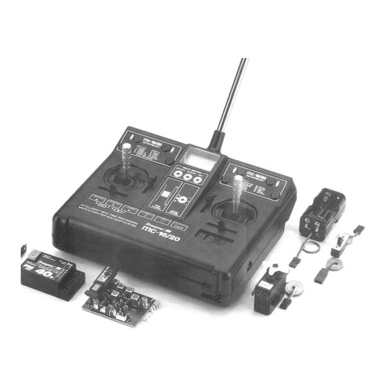
GRAUPNER Rotaryselect mc-16 Programming Handbook
Rotaryselect rc
Hide thumbs
Also See for Rotaryselect mc-16:
- Programming manual (104 pages) ,
- Programming manual (335 pages) ,
- Operating instructions manual (49 pages)
Subscribe to Our Youtube Channel
Summary of Contents for GRAUPNER Rotaryselect mc-16
- Page 2 Helicopter “HE” Description, Connection Diagram ........28 Menu Block Diagram............29 mc-16/20 Computer System 3 – 5 General Organisation of the Helicopter Model ..60 – 61 Diagram of Adjustments.......... 30 – 31 Basic Installation Instructions ........6 – 9 Description, Connection Diagram ........
- Page 3 Mixers, etc., since these functions are common to all mechanical mixers become unnecessary in the to make a meaningful program for the model to be model types at your disposal.
- Page 4 COMPUTER-SYSTEM 16/20 With ROTARY SELECT Programming High security using modern single chip computer technology. Newly developed LCD multi-data display with integrated static driver for precise, clear digital display. The extremely high contrast enables, even with bright sunlight, a precise check of the functions displayed in the transmitter display such as operating voltage, input data, mixer functions, settings, direction of rotation, trim and programming...
- Page 5 • Mixer for V-tail and delta models. For special applications (short time use) • Super helicopter program for normal swashplate, Further 4.8v batteries see Graupner main catalogue. HEIM, 120° systems or those with four linkages. • Three freely programmable mixers.
-
Page 6: Operating Instructions
Operating Instructions The resistance to movement of the control stick can Opening the Transmitter case Changing the proportional control sticks and changing the centring force. be adjusted between low to high by tightening or The removable back of the case is held by one loosening of the adjusting screw. - Page 7 (or recharge). disable this reverse current protection (e.g. for servo movements and their load. In the PCM mode Charger devices and batteries - see Graupner main measuring purposes or when connecting an the "Fail Safe" function can be activated, which will automatic loader), it is necessary that the enclosed catalogue telex.
- Page 8 Operating Instructions Changes of the HF channels: The channel is Frequency band and Channel change Installation the Module Change frequency band: The Transmitter can be determined by the crystal. Only crystals of the The Transmitter case is pre-drilled for the installation operated on different frequency bands by changing correct type and the appropriate frequency band may of the modules, like NAUTIC, Proportional and...
- Page 9 Fasten the NAUTIC modules Length adjustment of the control sticks Assembly of the Transmitter Carriers Insert the module into the intended location and that The length of the control sticks can be adjusted up to The transmitter can be equipped with the transmitter check it fits correctly.
- Page 10 Connection of External Module Installation Control Elements Pattern Function Modules See page 91 Model Type External Switch Connection Standard “FL” Unifly “UN” F3B/Butterfly “Fb” Aerobatic “AC” Helicopter “HE” Dual-Rate and Exponential for: Aileron Roll Dual-Rate and Exponential for: Elevator Pitch Dual-Rate and Exponential for: Rudder Tail Rotor Combi-mix (Aileron Rudder)


Need help?
Do you have a question about the Rotaryselect mc-16 and is the answer not in the manual?
Questions and answers