Table of Contents
Advertisement
Advertisement
Table of Contents

Related Manuals for GRAUPNER mz-18 HoTT


Summary of Contents for GRAUPNER mz-18 HoTT
- Page 1 Manual mz-18 HoTT / mz-24 HoTT No. S1005 / No. S1006 Manual part 1...
- Page 2 2 / 28 S1005_S1006_jp_V1...
-
Page 3: Table Of Contents
Index Introduction ................5 Service Centre ..............5 Intended use ................6 Target group ..............6 Package content ..............6 Technical Data ..............7 Declaration of conformity ...........7 Symbols explication ............8 Safety notes .................8 For your safety by handling the transmitter ......9 For your safety by handling the battery ......10 Description of the transmitter ..........12 Control elements on the transmitter .........12 Connection on the back side ...........13... - Page 4 Battery use timer in the display .........22 Use and menu functions ...........23 Operation of the key field ..........23 Entry lock ................23 Digital trim ...............24 Display ................24 Operation ..............24 Indications active/inactive fields ........24 Notes on environmental protection .........26 Care and maintenance ............26 Warranty certificate ............26 Display symbols ............26 Firmware update ...............27...
-
Page 5: Introduction
If you experience any trouble during operation, take the instructions to help or ask your dealer or Graupner Service Centre. NOTICE This manual is composed by two parts. Part 1 is contained in the product's package content. -
Page 6: Intended Use
Read through this entire manual before you attempt to install or use the transmitter. Graupner/SJ constantly works on the development of all prod- ucts; we reserve the right to change the item, its technology and equipment. Target group The product is not a toy. -
Page 7: Technical Data
The technical data of the optional receiver are available in the manual included in the receiver package content. Declaration of conformity S.1005 mz-18 HoTT S.1006 mz-24 HoTT Graupner/SJ declares that the product is conform to EU norms. EMV 2004/108/EC: EN 301 489-1 V1.9.2 EN 301 489-17 V2.1.1 EN 62479:2010... -
Page 8: Symbols Explication
Symbols explication Always observe the information indicated by this warning sign. Particularly those which are additionally marked with the CAU- TION or WARNING. The signal word WARNING indicates the poten- tial for serious injury, the signal word CAUTION indicates possibil- ity of lighter injuries. -
Page 9: For Your Safety By Handling The Transmitter
Protect all equipment from dust, dirt, moisture. All equip- ment must be protected from vibration as well as excessive heat or cold. The models may only be operated remotely in normal outside temperatures such as from -10°C to +55°C. ... -
Page 10: For Your Safety By Handling The Battery
For your safety by handling the battery CAUTION Protect all equipment from dust, dirt, moisture. Only use in dry locations. Do not use any damaged battery. Risk of injury! Any alterations to the battery can cause serious injury. Risk of fire! ... - Page 11 Special instructions To charge and discharge batteries, only use specifically designed chargers/dischargers with balancer connector. The white connector (cell count + 1 pole) is designed for the connection to a LiPo balancer or a battery charger as a sin- gle cell charger with a manual cell balancer.
-
Page 12: Description Of The Transmitter
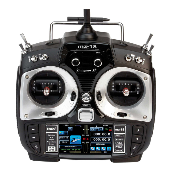
Description of the transmitter Control elements on the transmitter Antenna 13 On/off switch Proportional dial DV3 14 ESC button INC/DEC buttons DT2 15 Alternative selection buttons Switch SW 3 16 Left control stick Proportional dial DV4 17 Switch SW 5 Switch SW 4 18 Switch SW 6 Switch SW 8... -
Page 13: Connection On The Back Side
Data socket The data socket is suitable for connection of an optional smart box. You can find accessories on www.graupner.de. Ear phones port Though this interface both acoustic signals and voice messages are emitted. The volume can be controlled by "Voice volume" and "Signal vol- ume"... -
Page 14: Mini-Usb Connection
The data can be evaluated on a compatible computer using the programs found on the downloads page for the transmitter under www.graupner.de. You can connect the memory card to your PC by using a mem- ory card reader. Copy the data downloaded from the transmitter page on the web site in the related folder of the memory card. -
Page 15: Dsc Socket
This type of connection should therefore only be used if you protect yourself from electrostatic discharge while operating the simulator by wearing a commercially available grounding armband. Graupner therefore strongly recommends only using wireless simulators. 15 / 28... -
Page 16: Charging Socket
Charging socket Through the charging socket you can charge the transmitter battery using the supplied plug-in charger. DO NOT USE PLUG-IN CHARGERS BY OTHER MANUFACTURERS OR OTHER CHARGERS. The maximum charge current is 1,5 A. More information are available in the section "Charging the trans- mitter battery". -
Page 17: Commissioning
The red "RX" and green "TX" on the left and right of this switch symbol mean that the currently active model memory has once been linked to a Graupner-HoTT receiver but is presently not linked. If there is a connection, it will be indicated by a green colored numeric indication of the actual voltage of the receiver power supply in the field near "RX"... -
Page 18: Adjusting The Control Stick
Adjusting the control stick Both the left and right control sticks can optionally be set from neutralizing to non-neutralizing and vice versa. The control sticks' restoring force can also be adjusted. The related adjusting system is on the back of the transmitter in the battery compartment, under the rubber covers, and under the side grips attached with double-sided adhesive tape. -
Page 19: Control Sticks Length Adjustment
202, a standard 4.8 V (NiMH) for the FELD ST. ALARM FELD ST. 000% mz-18 HoTT transmitter and 3.6 V (lith.) for the mz-24 HoTT ESC STR ESC VOLT transmitter, a warning beep sounds, and the following window 000.0A... -
Page 20: Removing Transmitter Battery
tors and reverse polarity protection. Make sure that the polarity is correct. After the charge is complete disconnect the charger from the power source. The battery charger can be used only in dry spaces. A wet charger, even if re-dried, should no longer be used. Never use a damaged battery charger. - Page 21 Inserting the transmitter battery Connect the battery plug in the transmitter socket. Make sure that the polarity is correct. Pay attention to the respective "+" and "-" symbols near the socket. Red = + Black/brown = - Place the battery into its compartment and close the cover. 21 / 28 S1005_S1006_jp_V1...
-
Page 22: Battery Use Timer In The Display
NOTE The charging socket comes standard with a protection switch that protects against polarity reversal. Original Graupner automatic char- gers recognize the battery charge. In order to prevent damage to the protection switch and to the other components, charging current should never exceed 1 A. -
Page 23: Use And Menu Functions
Use and menu functions Operation of the key field The main operation of the transmitter is made by using the touch screen display. In some cases it is possible to use the buttons on the sides of the display. Keys left of the display Adjust buttons ... -
Page 24: Digital Trim
Digital trim Digital trim with an optical and acoustic display The two control sticks come with digital trimming. Briefly touch the trimming switch to move the neutral position of the control stick by a specific value with each click. If it is held, the trimming moves in the corresponding direction with increasing speed. - Page 25 Gray = inactive 25 / 28 S1005_S1006_jp_V1...
-
Page 26: Notes On Environmental Protection
Graphic display of the position of the proportional rotary transducers DV 1 (mz-18 HoTT) and DV 2 waste at the end of its life. It must be handed over to the appli- (mz-24 HoTT) with a numeric position and direction display. -
Page 27: Firmware Update
Only operate your transmitter using the current software version. these information can also be found at: www.graupner.de => Service & Support => Update and revision history for GRAUPNER HoTT components. Before each update, check the transmitter battery charge or ...
Need help?
Do you have a question about the mz-18 HoTT and is the answer not in the manual?
Questions and answers