GRAUPNER mz-24 PRO Manual
12 channel hott 2.4 ghz transmitter
Hide thumbs
Also See for mz-24 PRO:
- Programming manual (241 pages) ,
- Programming manual (240 pages) ,
- Programming manual (240 pages)

Subscribe to Our Youtube Channel
Related Manuals for GRAUPNER mz-24 PRO


Summary of Contents for GRAUPNER mz-24 PRO
- Page 1 Manual (Part 1) mz-24 PRO 12 Channel HoTT 2.4 GHz Transmitter No. S1006.PRO and S1006.PRO.S...
-
Page 2: Table Of Contents
Charging Socket Polarity ..... 11 Battery Use-time ........ 11 Data Recording and Saving ......12 Transmitter Setup ..............13 Turning on the Transmitter ......13 Mz-24 PRO menus ........13 BASE ............ 14 FUNCTION ........... 14 SYSTEM ..........15 TELEMETRY ......... 15 First-time Model Setup ....... - Page 3 INNOVATION & TECHNOLOGY Operation..........26 Active/Inactive Icons ......26 Lock Screen ......... 26 Display Symbols ........27 Stick Adjustment ......... 28 Stick Length Adjustment ......28 Firmware Update ..............29 Transmitter software update...... 29 Safety Notes ................ 30 Transmitter Safety ........30 Battery Safety ..........
-
Page 4: Introduction
The mz-24 PRO incorporates many functions and enhancements requested by our users and team pilots. The mz-24 PRO radio has many new features and added functionality. If you have used our mz-24 radio in the past, you should have no difficulties adapting to the new user interface. -
Page 5: Intended Use
♦ USB cable ♦ Adapter cable ♦ Transmitter neck strap ♦ Stylus ♦ mz-24 PRO User’s Manual (Part 1) ♦ Micro SD card ♦ Micro SD card adapter ♦ Transport case The Programming Manual (Part 2) can be found on the Downloads section or product page at www.graupnerusa.com. -
Page 6: Technical Data
INNOVATION & TECHNOLOGY Technical Data Transmitter mz-24 PRO HoTT Frequency band 2.4 to 2.4835 GHz Modulation FHSS Transmitting power 100 mW EIRP Control functions 12 functions of which 4 can be Temperature range 14°F to 131°F (-10°C to +55 °C) -
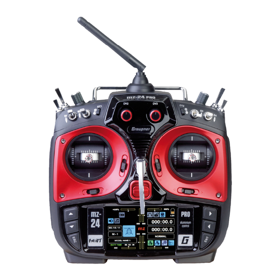
Page 7: Transmitter Description
INNOVATION & TECHNOLOGY Transmitter Description Transmitter Control Elements 16 15 10 9 Antenna 14 ESC button Proportional dial DV3 15 Alternative selection buttons INC/DEC buttons DT2 16 Left control stick Switch SW 3 17 Switch SW 5 Proportional dial DV4 18 Switch SW 6 Switch SW 4 19 Switch SW 1... -
Page 8: Neck-Strap Attachment
INNOVATION & TECHNOLOGY Neck-Strap Attachment The Neck-Strap Attachment arm is located on the front of the transmitter above the power button. Transmitter Back Side Connections Data Port Use the data port to connect the optional Smart Box P/N 33700 or Bluetooth adapter P/N S8351. -
Page 9: Mini-Usb Connection
The maximum charge current is 1.5 A. Refer to the Charging the Transmitter Battery section for additional information. Note USE THE SUPPLIED GRAUPNER PLUG-IN CHARGER ONLY. Serious damage can occur if the batteries are charged using products made by other manufacturers. -
Page 10: Transmitter Power Supply
INNOVATION & TECHNOLOGY Transmitter Power Supply BACK CLR AUTO LOAD OFF STRENGTH ALARM Monitor the transmitter battery voltage during operation via the battery icon in the upper right hand corner of the main display. A warning message will sound once the battery reaches the minimum voltage level and the screen shown at left will appear in the display. -
Page 11: Using An External Charger
3. A completely discharged battery requires approx. 15 hours to be recharged. Charging Socket Polarity Charging cables produced by other manufacturers often have different Graupner polarities. For safety reasons, you should only use original charging cables. NOTE The charging socket comes with a standard protection switch that protects Graupner against polarity reversal. -
Page 12: Data Recording And Saving
INNOVATION & TECHNOLOGY Data Recording and Saving Flight data logging is a powerful way to analyze flight performance and flight information generated during flight from the attached telemetry modules in your model. The data recording in the SD card is linked to the flight timer. When the flight timer is started, the flight data recording starts and stops when the flight timer is stopped. -
Page 13: Transmitter Setup
000:00.0 000:00.0 0:01:23 M- 1 PHASE 1 MODEL NAME 1 Mz-24 PRO menus There are four icons on the lower right hand corner that allow you direct access to each of the radio functions menus 13 / 34 S1006.PRO_mz-24_PRO_EN USA_V1... -
Page 14: Base
INNOVATION & TECHNOLOGY BASE The BASE menu provides access to all the basic functions to setup a model. Here you can setup a new mode, bind your receivers and fine tune your settings like reversing servo’s channel assignments, telemetry, voice notifications and more. -
Page 15: System
INNOVATION & TECHNOLOGY SYSTEM The SYSTEM menu allows you to setup your system preferences such radio mode settings, volume, alarms, MP3 player and display settings. TELEMETRY The TELEMETRY menu provides useful model information in real-time. Depending on your installed modules and sensors you will find a wealth of useful information about your models state and performance. - Page 16 INNOVATION & TECHNOLOGY Press the Model Memory button on the Home Screen display to bring up the Model Sel submenu: Highlight the MODEL NAME field by pressing the button next to the line number. Press the NEW button along the right hand side of the screen.
- Page 17 INNOVATION & TECHNOLOGY Press [ = ] to enter the new name into the New Model Name field at left: Select the WIZ. button to advance to the next screen. Select the model type by pressing the icon. The following images correlate to the AIRPLANE mode: Note: servo channels are defined on each...
- Page 18 INNOVATION & TECHNOLOGY A tail configuration screen appears. Select the appropriate icon for the model (refer to the model’s manual for tail configuration information). For this example, the NORMAL button was selected. The power system screen appears. Select the appropriate icon for the model’s power system. The REV/SUB menu appears.
- Page 19 INNOVATION & TECHNOLOGY Press the WIZ. button to advance to the E.P.A menu screen. Use this screen to set limits and travel for each channel. Press NEXT to set higher numbered channels. Press WIZ. To advance to the D/R,EXP menu. Use this screen to set up dual rates (D/R) and exponential (EXPO) for ailerons.
- Page 20 INNOVATION & TECHNOLOGY Use this screen to set throttle cut. Throttle Cut is used to stop Nitro and Gas engines or to prevent accidental starting of an electric motor. Propellers are extremely dangerous: pilots can inadvertently move the throttle stick with the swipe of a hand, elbow, or by brushing against the pants leg while walking to retrieve an aircraft.
- Page 21 INNOVATION & TECHNOLOGY For this example, SW5 is assigned to flaps by toggling the switch on the radio to record it to CH5 CH5 which is your flap channel can now be operated with SW5. In most cases we would like to have the flaps move slowly into position to reduce sudden attitude changes which can be done with slowing them movement down a bit.
-
Page 22: D/R And Exp Setup
INNOVATION & TECHNOLOGY D/R and EXP Setup Dual Rates (D/R) are used to change the aircraft’s response to stick movements. Beginners often over-control a model by moving the sticks too aggressively. Skilled pilots may want larger control movements while performing a 3D maneuvers, but smaller control movements during landing. -
Page 23: Ctl And Sym Option
INNOVATION & TECHNOLOGY CTL and SYM Option CTL = control device. The control device can be assigned to any control on the transmitter: switch, slide, knob, or stick position. To activate the CTL function, press the NULL button in the CTL line. A popup window appears: SERVO BACK Select... -
Page 24: Gr-12L Receiver
INNOVATION & TECHNOLOGY RECEIVERS ARE DIFFERENT FROM ALL OTHER GRAUPNER RECEIVERS. GR-12L Receiver ♦ When the receiver is not bound, the LED glows solid RED ♦ When bound, the LED flashes intermittently. ♦ When in bind mode, the LED is OFF and it only stays in binding mode for a few seconds. -
Page 25: Menu Functions
INNOVATION & TECHNOLOGY Menu Functions Keypad Most Home Screen operations are used by touching the display screen. To set parameters, scroll through options, select or clear certain functions, use the keypad controls at either side of the display screen. Adjust Buttons (Left of Display) ♦... -
Page 26: Display Screen
INNOVATION & TECHNOLOGY Display Screen Operation Operate the display screen by touching fields and icons with either a finger or the provided stylus. Active/Inactive Icons Refer to the color of an icon to determine if its function is active or inactive: Blue = active Gray = inactive... -
Page 27: Display Symbols
INNOVATION & TECHNOLOGY Display Symbols 1 2 3 4 5 6 7 8 9 10 12 13 14 15 16 17 18 19 20 21 Model operating time MP3 Player icon RF On/Off icon Visual trim indicator for DV 2 Model type graphic Visual trim indicator for DV 1 Visual trim indicator for DV 2... -
Page 28: Stick Adjustment
INNOVATION & TECHNOLOGY Stick Adjustment All adjustments can be made on the back side of the transmitter without opening the transmitter case using a cross head screwdriver. Battery Compartment Screwsets Two sets of screws can be reached through the battery compartment, one for each stick. -
Page 29: Firmware Update
INNOVATION & TECHNOLOGY Firmware Update Transmitter firmware, programs, files and software required for updates are available for download at www.graupnerusa.com. Look for the Firmware Update Studio program in the download section. Use the USB port on the back of the transmitter to upload the updates. Note ♦... -
Page 30: Safety Notes
♦ Save the log file of the model after each use. Information in the log can help to diagnose technical failures, and be used to submit claims about performance. ♦ For additional questions or support, contact the Graupner USA Service Center, or an experienced user. Transmitter Safety WARNING Rotating propellers can cause injury. -
Page 31: Battery Safety
INNOVATION & TECHNOLOGY Battery Safety CAUTION ♦ Protect batteries from dust, moisture, heat and vibrations. For use in dry locations only. ♦ Do not use damaged batteries. ♦ Batteries should not be altered, heated, burned, short- circuited, incorrectly inserted, modified, soldered or welded. -
Page 32: Lipo Battery Storage And Safety Notes
♦ Exercise safety precautions when charging transporting your LiPo batteries. Always use a safety bag. Declaration of Conformity FCC-SNL-36204410 Graupner/SJ declares that the product is conform to EU norms. EMV 2004/108/EC: EN 301 489-1 V1.9.2 EN 301 489-17 V2.1.1 EN 62479:2010... -
Page 33: Warranty Certificate
Clean the product by lightly rubbing with a dry cloth. Do not use detergent! Warranty Certificate Graupner USA – OPENHOBBY LLC at 3941 Park Drive Suite 20-571, El Dorado Hills, CA 95762 warranties this product from the date of purchase for a period of 24 months. - Page 34 INNOVATION & TECHNOLOGY Notes 34 / 34 S1006.PRO_mz-24_PRO_EN USA...
Need help?
Do you have a question about the mz-24 PRO and is the answer not in the manual?
Questions and answers