
Related Manuals for GRAUPNER m-12 HOTT


Summary of Contents for GRAUPNER m-12 HOTT
- Page 1 No. S1002.mz-12 HoTT. USA mz-12 OPERATING INSTRUCTION Prior to use, please read this manual thoroughly. Keep this manual in a convenient place for quick and easy reference.
-
Page 2: Table Of Contents
Contents 7. Wing mix (AIRCRAFT) • Before Use - Diff aile • Support and Service - Diff flap 33~34P - Customer support - Aile->rudd - Internet sales site - Aile->flap 34~35P - A/S regulation - Brak->elev - Warranty regulation - Brak->flap •... -
Page 3: Openhobby A/S Center
Frequently Asked Ques- incompatible components or augment product in any way without the approval of Graupner. This man- tions (on the web pages referenced below), your hobby dealer, or the Graupner Service ual contains instructions for safety, operation and maintenance. -
Page 4: Transmitter Control Identification
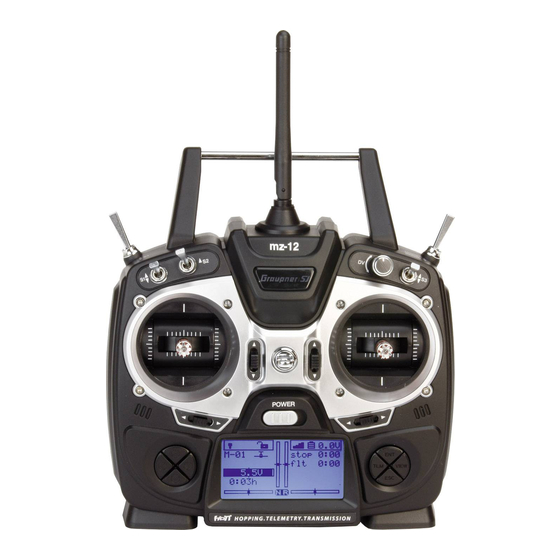
4. TRANSMITTER CONTROL IDENTIFICATION ANTENNA TX HANDEL RF T RAINER SW IT CH S4 SWITCH S2 SWITCH DIAL VOLUME S3 SWITCH S1 SWITCH BATTERY COVER NECKSTRAP LUG ELEV/RUDO STICK THRO/AILE STICK ELEV/TRIM THRO TRIM POWER SWITCH AILE TRIM RUDD TRIM ENT, ESC, TEL DIRECTION VIEW BUTTON... -
Page 5: Specification
5. SPECIFICATION 7. ADJUSTABLE STICK LENGTH The control stick is consisted of 2pc of stick levers and it allows you to adjust the control Transmitter mz-12 Receiver 8 Ch stick’s length as you want. Frequency band 2.4~2.4835GHz 2.4~2.4835GHz 1. Hold the lever “B” and turn the lever “A” Modulation FHSS FHSS... -
Page 6: Mode Exchange Of Throttle Stick For Mode 1 And Mode
9. Mode exchange of throttle stick for Mode 1 and Mode 2 Screw the disassembled bolt from Unscrew the tension spring control the throttle gimbal of mode 1 trans- Unscrew the transmitter’s rear case Disassemble the centering cam bolt in the elevator gimbal of mode mitter into the elevator gimbal to fix and remove the rear case and disas- form the gimbal... - Page 7 Assemble the centering cam into the Screw the disassembled tension throttle gimbal of mode 1 transmitter control bolt from the elevator gimbal and set the spring in the center of mode 1 transmitter into the throttle control part and the centering cam gimbal and adjust the bolt for the with tweezers desired control...
-
Page 8: What Is Hott 8P
Optional NiCd or NiMH 1.2-volt AA rechargeable 4-cell batteries can be used. A battery con- According to your preference, you can adjust the spring tension by tightening the related screws necter is on the inside of the transmitter for convenient recharging. Graupner offers rechargea- for elevator, aileron and rudder stick. -
Page 9: The Transmitter Programming Setup
2. The model men is highlighted then press the direction button to highlight RF sett. 4. After completing the bind, press the ESC button to return to the home screen. press 3. Press the ENT button, the cursor is automatically on the stick mode line then press the direction button to select the hyphen in the rx bind line. -
Page 10: Select Model 10P
press press - Select model press In the home screen, press the ENT button then the model mem is highlighted. Press the ENT button to access the function. press - Model name When the model mem is highlighted, press the ENT button then the cursor is on the select model line. -
Page 11: Clear Model 11P
press press press press press press press press - Clear model When the model mem is highlighted, press the ENT button then the cursor is on the se- lect model line. Press the direction button to select the clear model line then press the ENT button to access to the function. -
Page 12: Copy Mod->Mod 12P
- Copy mod->mod press The model mem is highlighted in the menu screen then press the ENT button. The cursor is on the select model line. Press the direction button to select the copy mod ->mod line then press the ENT button to access to the function. When the copy from model screen appears, press the direction button to highlight the model you want to copy then press the ENT button to accept. - Page 13 press • Quick link set : The quick link sett function allows to adjust the D/R expo value and to assign the corresponding switch to cope with various flight conditions such as 3D flight or the flight with the strong wind. Since the adjusted value is activated by moving the switch, you can cope with various flight conditions with switch.
- Page 14 - Cut off When the option of “idle re” or “idle fr” is selected, the cut off option is activated. It turns off the internal combustion engine or the electric motor. Press the ENT button to remove the highlight of the motor at C1 value then press the direction button to select the cut off line.
- Page 15 Press the direction button to select the value,+150%,. Place the throttle stick at the desired press position and press the ENT button then the adjusted value is applied (The adjusted value is activated when the throttle stick is in that position). NOTE : the value,+150%, is the throttle stick position where the cut off function is activated.
-
Page 16: Motor At C1
Motor at C1 no, no/inv Idle re, idel fr Tail type normal,V-tail,delt/FlW 2 elev sv normal,V-tail Delt/FlW 2 elev sv 2 aile 1 aile 1 aile 1 aile 1aile 2 aile 1 flap 1 aile 1 flap 1 aile 1 flap 1 aile 1 flap 1 aile 1 flap Aile/flap... -
Page 17: Quick Link Sett 17~18P
press press press press press press press - Quick link sett The quick link sett function allows to adjust the D/R expo value and to assign the corre- sponding switch to cope with various flight conditions such as 3D flight or the flight with the strong wind. -
Page 18: Quick Link Trim 18~19P
press press press press - Quick link trim Use the quick link trim function to program the appropriate trims of the quick 2 and quick 3 in the quick link. The user can program the trim in advance to cope with the unexpected situation such as the flight with the strong wind and match the flight situation of the takeoff , thermal and speed press of the glider. -
Page 19: Rotor Direct 22P
After completing the normal quick link adjustment, press the direction button to select the thermal quick link line. The thermal quick link and speed quick link can be programmed in the same method. If you already set the quick link switch and the switch is ON, the cursor is automatically moved to the corresponding quick link value. -
Page 20: Quick Link Sett 23~24P
• Aurtorotat press You may set the switch to be used as auto rotation. If the switch is on, throttle channel is hold at 90% position and pitch, elevator and aileron that is connected to throttle channel are normal operated. It is the same function with throttle hold. •... - Page 21 press - Cut off Press the direction button to select the cut off line then press the ENT and the direction button to highlight and adjust the value less than -100%. Press the ESC button to remove the highlight. NOTE : The value of -100% is the cut off position the user can program, if the cut off value is programmed less than -100%, the breathing hole of Engine carburetor is block or the press speed controller lets the motor off so the power is not delivered to the Helicopter.
- Page 22 - Pitch min Use the pitch min function to reverse the servo direction in all of pitch, elevator, aileron and throttle channels, the default value is rear. Available settings are rear and front. Press the direction button to select the pith min line then press the ENT button to high- light the pitch min value.
- Page 23 press press press press press - Quick link sett press The quick link sett function allows to adjust the quick2 value and assign the corresponding switch to cope with various flight conditions such as 3D flight or the flight with the strong wind. Since the adjusted value is activated by moving the switch, you can cope with various flight conditions with switch.
-
Page 24: Servo Sett (Aircraft And Helicopter)
3. Servo sett (Aircraft and Helicopter) The servo sett adjusts the servo reverse, center, travel for all six channels. - Rev : used to reverse the servo direction for all channels. - Cent : used to set the neutral position of the servo. - Trv : used to increase or decrease the moving angle of the servo travel. - Page 25 press press press press press press press press press press press press press...
-
Page 26: Cont Sett (Aircraft And Helicopter) 26~27P
press press press press 4. Cont sett (Aircraft and Helicopter) It contains 3 categories: model type, quick link set and quick link trim. You can program the 5 and 6 channels in mz-12 to the special function that you want. Typically, the 5 channel is used for the on/off switch of the retractor gear and the 6 channel is used for the on/off switch of the flap function. - Page 27 press press press press press press press press - Cont sett (Helicopter) The basic setting of the Helicopter cont sett is NO.5 gyro, NO6. Throttle, Lim. DV (Digital volume). Generally, this function is seldom used, but Lim. DV (Digital volume) can control the operation range of digital volume -100 ~ +100.
- Page 28 5. D/R expo (Aircraft and Helicopter) The basic setting of the Helicopter cont sett is NO.5 gyro, NO6. Throttle, Lim. DV (Digital volume). Generally, this function is seldom used, but Lim. DV (Digital volume) can control the operation range of digital volume -100 ~ +100. If DV is programmed, throttle channel is operated only programmed range.
-
Page 29: Rf Sett (Aircraft And Helicopter) 29P
press • Timer The mz-12 has four stick modes with the two dual axis sticks. The user can select one among the four default stick modes the default mode is the mode 1. • Receiv out For the maximum flexibility of the receiver socket assignment, the mz-12 provides to swap over the servo outputs 1 to max.6. - Page 30 - Stick mode Enter the stick mode from the RF sett on the menu. Press the ENT button to highlight the value then press the direction button to select the mode number of 4 modes. press press press press press press press - Timer...
-
Page 31: Rx Bind 31P
Press the direction button to select the range test, the cursor is at the 99sec. Turn on the re- press ceiver then press the ENT button on the transmitter. With the range test started, the Graupner logo blinks with beep for 99sec. Walk over 50 meters away from the model with controlling the transmitter sticks constantly and check whether the model is operating normally. -
Page 32: Rf Transmit 32P
7. wing mix (AIRCRAFT) press • Diff aile The diff aile mixing allows to overcome the adverse yaw when the Aircraft is deflected. the servo travel of the aileron channel is so adjusted that the flight vertical axis is straightened. •... - Page 33 - Diff aile Press the ENT button to access the diff aile mixing then press the ENT button again to highlight the value. Press the direction button to adjust the desired value then press the ESC button to remove the highlight. Press the direction button to select the hyphen then press the ENT button.
- Page 34 press press press press - Ail->rudd Press the direction button to select the ail -> rudd line and press the ENT button to highlight the value. Press the direction button to adjust the desired value then press the ESC button to remove the highlight.
- Page 35 press press press press press press press press - Brak->elev Press the direction button to select the brak -> elev line and press the ENT button to highlight the value. Press the direction button to adjust the desired value then press the ESC button to remove the highlight.
- Page 36 - Brak->flap Press the direction button to select the brak -> flap line and press the ENT button to highlight the value. Press the direction button to adjust the desired value then press the ESC button to remove the highlight. Press the direction button to select the hyphen then press the ENT button.
- Page 37 press - Elev->flap Press the direction button to select the elec -> flap line and press the ENT button to highlight the value. Press the direction button to adjust the desired value then press the ESC button to remove the highlight. Press the direction button to select the hyphen then press the ENT button.
- Page 38 press press press press press - Flap->elev Press the direction button to select the flap -> elev line and press the ENT button to highlight the value. Press the direction button to adjust the desired value then press the ESC button to remove the highlight.
-
Page 39: Heli Mix (Helicopter) 39P
press press press press press press 8. heli mix (Helicopter) The mz-12 offers the mixing function in Helicopter model type. Heli mix is connected to 2 quick link function and the mixes are assigned to each quick link function. • Ptch : The ptch mixing allows to adjust 5 points of the pitch curve that corresponds to the throttle stick to maintain the best flight condition. - Page 40 - Ptch Press ENT button to access the ptch mixing then press the ENT button again to access the function. -100% of the point 1 value is highlighted. Move the throttle stick to the high position step by step then the point 2,3,4,5 is selected in turn. After selecting the point number, press the direction button to adjust the desired value.
-
Page 41: Pitc-Thro 41~42P
press - Pitc->thro Press the direction button to select pitc->thro line and press the ENT button to access the pitc->thro function. 0% of the point 1 value is highlighted. Move the throttle stick to the high position step by step then the point 2,3,4,5 is selected in turn. After selecting the point number, press the direction button to adjust the desired value. -
Page 42: Pitc-Rudd 42~43P
- Pitc->rudd ruddPress the direction button to select pitc->tail line and press the ENT button to access the pitc-> tail function. 0% of the point 1 value is highlighted. Move the throttle stick to the high position step by step then the point 2,3,4,5 is selected in turn. After selecting the point number, press the direction button to adjust the desired value. -
Page 43: Rudd-Thro 43P
- Aile-thro Press the direction button to select aile – thro line and press the ENT button to access the aile – thro function. The value 0% is highlighted then press the direction button to adjust the desired value. press - Rudd-thro Press the direction button to select rudd –... -
Page 44: Swash Lim 44~45P
press press press - Swash lim press Press the direction button to select the swash lim mixing then press the ENT button to access the function. off of the swash lim value is highlighted. Press the direction button to adjust the desired the gain then press the ESC button to remove the highlight. press - Gyro Press the direction button to select the gyro mixing line then press the ENT button to ac-... -
Page 45: Governor 8Ch 45P
press - Governor 8ch Press the direction button to select the governor 8ch then press the ENT button to access the function. The value no of is highlighted. You may select yes or no by the direction press button. Press the ESC button to remove the highlight. press 9. - Page 46 press press press press press press press press press press press press press...
- Page 47 press press press press press press press press - ASY To adjust the different value for the master channel, press the direction button to highlight the ASY from the SYM then press the ENT button to highlight the trv value in the right. Move the stick of the master channel then you can select the trv value in the right side or left side.
-
Page 48: Swash Mix (Helicopter)
press 10. Swash mix (Helicopter) The Swash mix adjusts the amount and direction of travel for the aileron, elevator and pitch functions. You can adjust the high/low travel range of the swashplate and prevent from the mechanical interference of the linkage. - SEL Press the direction button to select the offset line then the STO is highlighted. -
Page 49: Basic Sett (Aircraft And Helicopter) 49P
- Batt type Press the direction button to highlight the basic sett then press the ENT button to access the Batt type line. Press the ENT button to highlight the value then press the direction button to adjust the value. Press the ESC button to remove the highlight. You may select the function of which you wish to adjust the value by pressing the direction button. - Page 50 - Touch sense - Batt warning The same method is used to access the function and adjust the value with Batt type programming. Press the direction button to access the Batt warning line then press the ENT button to highlight the value.
- Page 51 press press press press press press - RF country The same method is used to access the function and adjust the value with Batt type program- ming. press - Display light The same method is used to access the function and adjust the value with Batt type programming.
- Page 52 press press - Beep volume The same method is used to access the function and adjust the value with Batt type programming. press - Voice volume The same method is used to access the function and adjust the value with Batt type programming.
-
Page 53: Fail Safe (Aircraft And Helicopter)
When you bind your transmitter, you are programming the receiver with failsafe defaults. If connection is lost between the transmitter and receiver, the receiver immediately oper- ates in those preprogrammed default positions. Graupner receiver has 2 failsafe modes, hold and Pos (Position/Fail Safe) -
Page 54: Trainer (Aircraft And Helicopter)
press press press 13. Trainer (Aircraft and Helicopter) The mz-12 has the trainer function. The function activates when you select Teacher, Pupil press and Normal mode. You may use this function by wireless and wired. - The teacher mode programming setup Press the direction button to highlight the teach pupil then press the ENT button to access the function. -
Page 55: Info Disp (Aircraft And Helicopter)
press press press press - The pupil mode programming setup After selecting the n/a in the BIND, press the ENT button then bind to the teacher transmitter. The pupil transmitter doesn’t need to program the other value. When the teacher transmitter to the pupil transmitter has been bound, the teacher transmitter can control all channels and if RF trainer switch of the teacher transmitter would be moved to PUPIL position, the pupil transmitter can control all channels 14. -
Page 56: Telemetry (Aircraft And Helicopter)
16. SETTING & DATA VIEW 15. Telemetry This function is used to program receiver and telemetry sensor and get the data information Telemetry is used to perform HoTT telemetry programming setup and check HoTT telemetry on them. This function can be accessed only if transmitter and receiver are bound. If not, data. -
Page 57: Rx Servo
16-2. RX SERVO This function allows you to perform servo programming set up at the entries of OUTPUT CH REVERSE, CENTER, TRIM, LIMIT-, LIMIT+, PERIOD. Press the direction button on RX DATA VIEW mode to access to RX SERVO then press DOWN button to select the desired article. - Page 58 - CENTER The value of servo center in the selected channel at OUTPUT CH can be programmed. The press center value depends on transmitter throttle and trim position. General servo center value is 1500us. Press DOWN button to access to CENTER line then press ENT button to highlight the default value 1500usec.
-
Page 59: Rx Fail Safe
press press press press press press 16-3. RX FAIL SAFE - PERIOD The servo response time for transmitter throttle can be adjusted. All channels that servo OUTPUT CH (receiver)/ INPUT CH (transmitter): It is used to perform the programming connected are applied separately. Press DOWN button to access to PERIOD line then setup of transmitter channel that is bound to receiver. - Page 60 - MODE It is failsafe mode and HOLD/ FAIL SAFE/ HOLD are available. Press DOWN button to access to MODE line then press ENT button to highlight the default value HOLD. Press UP/DOWN button to select the desired value then press ENT button to remove the highlight.
- Page 61 - F.S.POS. - DELAY It is used to set fail safe position at the desired channel that you select on OUTPUT CH. This function allows you to set the time that failsafe takes to start under failsafe situation Press DOWN button to access to F.S. Pos line then press ENT button to highlight the Press DOWN button to access to DELAY line then press ENT button to highlight the default default value 1500usec.
-
Page 62: Rx Free Mixer
- FAIL SAFE ALL It is used when you change failsafe position value of all channels. You need set all channels to 16-4. RX FREE MIXER FAIL SAFE to use this function. Press DOWN button to access to FAIL SAFE ALL line then press ENT button to highlight the This function allows you to perform the FREE MIXER programming setup. - Page 63 - MASTER CH - SLAVE CH Master CH in FREE MIXER can be selected. Slave CH in FREE MIXER can be selected. Press DOWN button to access to MASTER CH line then press ENT button to highlight Press DOWN button to access to SLAVE CH line then press ENT button to highlight the the default value 00.
- Page 64 - S-TRAVEL + / - The maximum servo travel that is connected to slave channel can be programmed. Press DOWN button to access to S- TRAVEL+/- line then press ENT button to highlight the default value 00. Press UP/DOWN button to select the desired channel then press ENT button to remove the highlight.
-
Page 65: Rx Curve
press press press press press press 16-5. RX CURVE Perform the exponential programming setup at RX CURVE mode. You may program the exponential value of channel 2,3,4. The default setup is B curve that leads Servo press responds proportionally depending on transmitter throttle movement. A curve leads that Servo responds sensitively and C curve leads that Servo responds softly. -
Page 66: Rx Servo Test
press 16-6. RX SERVO TEST It used to perform servo test and program the voltage of receiver power, the max/min temperature of receiver CH OUT TYPE of receiver. Press UP/DOWN buttons to select the desired line and press ENT button then the default value is highlighted. Press UP/DOWN buttons to set the desired value and press ENT button to remove the highlight. - Page 67 press press press press press press - ALARM TEMP + / - : Temperature warning - ALARM VOLT : Low voltage warning If receiver temperature is out of the preset temperature, transmitter repeats a beep warning. If receiver voltage is out of the preset voltage, transmitter repeats a beep warning. Press DOWN buttons to access to ALARM TEMP and press ENT button then the default Press DOWN buttons to access to ALARM VOLT and press ENT button then the default value is highlighted.
- Page 68 press CH OUT TYPE You may decide the signal output type of receiver. 5 types of ONCE / SAME / SUMO12/ SUMI / SUMD HD12 are available. press press - ONCE It is use for analogue servo. If ONCE is selected, PERIOD on RX SERVO is set to 20msec automatically.
-
Page 69: Sensor Select
press press press press press 17. SENSOR SELECT press It is used to program telemetry sensor that is connected to HoTT receiver. The sensor should be connected to the telemetry pin of receiver to use voice function, warning and the telemetry data information. Press DOWN buttons to go to SENSOR SELECT line and press ENT button to access the function. -
Page 70: Rf Status View
press press press press 19. VOICE TRIGGER It is used to program the sensors related with voice function. The default article REPEAT, TRIG, VARIO, TRANSSMITTER, RECEIVER are available and the optional sensors could be attached. If the optional sensor is connected, it is need to add the function for the optional sensor at SENSOR SELECT mode then VOICE TRIGGER article is created. - Page 71 press press - TRIG You may designate the switch for the voice functions of transmitter and receiver and the voice functions are changed in turn whenever the switch is on/off. Press DOWN buttons to access to TRIG and press ENT button then the popup message “push de- sired switch into position on”...
- Page 72 - VARIO - TRANSMITTER You may set the on/off switch of vario module for voice function. You may program the telemetry voice function of transmitter, TX VOLT, BATTERY TIME, Press DOWN buttons to access to VARIO and press ENT button then the popup message STOPWATCH, RUNTIME, Press DOWN buttons to go to TRANSMITTER line and press “push desired switch into position on”...
-
Page 73: The Programming Setup For Telemetry Sensors
- RECEIVER - If the optional sensors are attached, the telemetry voice functions of an attached option- You may program the telemetry voice function of receiver, TEMP, STRENGTH, RX al sensors can be programmed. It is need to add the function for the optional sensor at VOLT, LOWVOLT, Press DOWN buttons to go to RECEIVER line and press ENT button SENSOR SELECT mode then VOICE TRIGGER article is created. - Page 74 press press press press press press press press...
-
Page 75: Safety Approval
• FCC Information Product(s) : Graupner mz-12 Transmitter press Contains FCC ID: SNL-36204210 FCC 47 CFR PART 15B Product(s) : Graupner HoTT GR-16(L) (8 channels) Receiver FCC ID : ZKZ-33508 FCC 47 CFR PART 15C • FCC Statement 1. This device complies with Part 15 of the FCC Rules. Operation is subject to the following two conditions: •... - Page 76 -KN 301 489-17:2009 the produce -KN 61000-4-2:2008 -KN 61000-4-3:2011 Product(s) : Graupner HoTT GR-16(L) (8 channels) Receiver - KCC인증번호: KCC-CRM-sjr-16003120 - 방송통신위원회고시 제2013-01호 - 방송통신위원회고시 제2012-102호 “신고하지 아니하고 개설할 수 있는 무선기기” 국립전파 연구원의 전자파 적합등록을 획득하였습니다.
- Page 77 mz-12...
Need help?
Do you have a question about the m-12 HOTT and is the answer not in the manual?
Questions and answers
jak sparovat vysilač Graupner HOOT mz 12 s jeho přijímačem