Table of Contents
Advertisement
Quick Links
Controller for servo and stepping motors
EMP400 Series
Thank you for purchasing an Oriental Motor product.
This Operating Manual describes product handling procedures and safety precautions.
Please read it thoroughly to ensure safe operation.
Always keep the manual where it is readily available.
OPERATING MANUAL
HP-19036
1
2
3
4
5
6
7
8
9
10
11
Advertisement
Table of Contents

Summary of Contents for Vexta EMP400 Series
- Page 1 HP-19036 Controller for servo and stepping motors EMP400 Series OPERATING MANUAL Thank you for purchasing an Oriental Motor product. This Operating Manual describes product handling procedures and safety precautions. Please read it thoroughly to ensure safe operation. Always keep the manual where it is readily available.
- Page 2 The product described in this manual has been designed and manufactured for use in general industrial machinery, and must not be used for any other purpose. Use a DC power supply with reinforced insulation provided on the primary and secondary sides as the power source for the controller and input/output signals.
-
Page 3: Table Of Contents
Important safety instructions ..........2-2 Precautions for use ............2-4 Preparations Checking the product ............3-2 Names of parts ..............3-3 Specifications of EMP400 series ........3-4 Installation Location for installation ............. 4-2 Orientation ................ 4-2 Installation method ............4-3 Connection Assembling the connector .......... - Page 4 Writing and editing a program How to write a sequence program ........6-2 Additional information on program composition ....6-3 6.2.1 Sequence program ............6-3 6.2.2 Parameter settings for motor operation ......6-3 Starting and exiting HyperTerminal ........6-4 6.3.1 Verifying the communication method ......
- Page 5 EEN ..................... 8-20 END .................... 8-21 ENDL ..................8-22 ETIME ..................8-23 H ....................8-24 ID ....................8-25 IN ....................8-26 INC ....................8-27 JMP ..................... 8-28 LOOP ..................8-29 MHOME ..................8-30 MU ....................8-32 OFS ..................... 8-33 OUT ..................... 8-34 PULSE ..................
- Page 6 Troubleshooting 10.1 When ALARM LED illuminates ........10-2 10.1.1 Main causes of an alarm ..........10-2 10.2 Error messages .............. 10-3 Sample programs 11.1 Operation by the host controller ........11-2 11.2 Speed change operation by the host controller ....11-3 11.3 Speed change operation at a specified time ....
-
Page 7: Introduction
Introduction Explains the items you should know before using this product. -
Page 8: Main Features
The controller features eight and six general-purpose inputs and outputs points, respectively. Motor control via multiple sources The EMP400 Series allows motor operation either from the host controller or a personal computer. The motor can be operated via the host controller by selecting 32 different sequence programs through unique combinations of different states of program selection inputs connected to the host controller and activating the START input. -
Page 9: Safety Precautions
Safety precautions This section covers safety precautions to ensure safe operation of the product. -
Page 10: Important Safety Instructions
Safety precautions Important Safety Instructions Only qualified personnel should work with the product. Use the product correctly after thoroughly reading the section “Safety precautions.” The precautions described below are intended to prevent danger or injury to the user and other personnel through safe, correct use of the product. - Page 11 Safety precautions Caution General Do not use the controller beyond their specifications, or injury or damage to equipment may result. Keep your fingers and objects out of the openings in the controller, or fire may result. Installation Keep the area around the controller, and data setter free of combustible materials in order to prevent fire or a burn.
-
Page 12: Precautions For Use
Precautions for use This section covers limitations and requirements the user should consider when using the controller EMP400 series and the data setter OP300. Power capacity For the controller, use a DC power supply capable of supplying 24VDC ±5% at 0.45A or greater, with reinforced insulation provided on the primary and secondary sides. -
Page 13: Preparations
Preparations This section covers the items that needs to be checked after purchasing the product, along with the names, functions and main specifications of components in the controller. -
Page 14: Checking The Product
3 3 3 3 3 Preparations Checking the product Upon opening the package, verify that the items listed below are included. In case any of these items is missing or damaged, check the model number shown on the package label and contact the branch or sales office from which you purchased the product. series controller 1 unit I/O connector (50 pins) 1 set ∗... -
Page 15: Names Of Parts
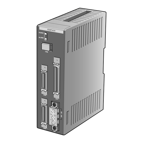
3 3 3 3 3 Preparations Names of parts This section covers the names and functions of parts in the controller. POWER LED Lit when the power is on. ALARM LED Modular connector (CN2) Lit when an alarm event occurs. Used to connect the cable for communication with terminals such as a PC and operational... -
Page 16: Specifications Of Emp400 Series
3 3 3 3 3 Preparations Specifications of EMP400 series Control axis number 1 or 2 Number of sequence programs 32 (sequence programs 0 through 31) The sequence program 99 is a CONFIG program. Number of program lines 1,000 lines... -
Page 17: Installation
Installation This section covers the conditions and method for controller installation. -
Page 18: Location For Installation
4 4 4 4 4 Installation Location for installation This controller is designed and manufactured for installation in equipment. Since heat generated from the controller is dissipated via air convection, install the controller in a well ventilated area that ensures easy maintenance. The conditions of the installation location are as follows: Inside an enclosure that is installed indoors (provide vent holes) Operating ambient temperature 0°C to +50°C (+32°F to + 122°F) (non-freezing) -
Page 19: Installation Method
4 4 4 4 4 Installation Installation method Mount the controller on a DIN rail. In case the DIN rail produces significant vibrations, mount the controller on an appropriate metal plate. Do not place any equipment that generates excessive heat or noise in the vicinity of the controller. Warning Check and reexamine the means of ventilation if the ambient temperature of the controller exceeds 50°C (122°F). - Page 20 4 4 4 4 4 Installation...
-
Page 21: Connection
Connection This section covers the methods for connecting the power, driver, host controller and other units to the EMP400 Series controller, as well as the grounding method, input/output circuits and a connection example. -
Page 22: Assembling The Connector
5 5 5 5 5 Connection Assembling the connector Solder-type connectors are supplied with the EMP401-2 and EMP402-2 series controllers. Solder the host controller cable for the I/O connector and the driver cable for the AXIS connector. The following figure shows the pin arrangement of the connector.(Viewed from the soldering side) I/O connector AXIS connector Solder a cable to the half-pitch connector. -
Page 23: Connecting To The Power Supply
5 5 5 5 5 Connection Connecting to the power supply The controller’s power supply is connected to the TB1 terminals. In addition to the power-supply terminals, TB1 has a frame ground (FG) terminal to prevent malfunctions caused by external noise. The power supply provides a voltage of 24VDC ±... -
Page 24: Connecting The Host Controller (Cn1)
5 5 5 5 5 Connection Connecting the host controller (CN1) 5.3.1 Connection method Use the I/O connector (50-pin) for connection with the host Screw controller. Plug the I/O connector into CN1 and tighten the screw. CN1 (I/O) signal table Pin No. -
Page 25: Internal Input Circuit
5 5 5 5 5 Connection 5.3.2 Internal input circuit The signal state represents the “ON: Carrying current” or “OFF: Not carrying current” state of the internal photocoupler rather than the voltage level of the signal. PS2801 or 5.4k equivalent +COM E-STOP, START S-STOP, IN1 to IN8... -
Page 26: Internal Output Circuit
5 5 5 5 5 Connection 5.3.3 Internal output circuit The signal state represents the “ON: Carrying current” or “OFF: Not carrying current” state of the internal photocoupler rather than the voltage level of the signal. +COM ALM, MOVE, READY OUT1 to OUT6, END +5∼24VDC 25mA max. - Page 27 5 5 5 5 5 Connection 5.3.4 Connection example to a host controller Series +COM input +COM input +COM input +5~24VDC 25mA max. 24VDC E-STOP input ALM output START input MOVE output S-STOP input READY output M0 input END output M4 input OUT1 output IN1 input...
-
Page 28: Connecting The Driver
5 5 5 5 5 Connection ∗EMP402 only Connecting the driver (CN3·CN4 5.4.1 Connection method Use the AXIS connector (26-pin) for connection with the driver. Screw Plug the AXIS connectors for the first- and second-axis drivers into CN3 and CN4, respectively, and tighten them with screws. -
Page 29: Internal Input Circuit
5 5 5 5 5 Connection 5.4.2 Internal input circuit The signal state represents the “ON: Carrying current” or “OFF: Not carrying current” state of the internal photocoupler rather than the voltage level of the signal. +12V PS2801 or equivalent 1kΩ... -
Page 30: Internal Output Circuit
5 5 5 5 5 Connection 5.4.3 Internal output circuit The signal state represents the “ON: Carrying current” or “OFF: Not carrying current” state of the internal photocoupler rather than the voltage level of the signal. +12V +12V 74LS06 or 560Ω... - Page 31 5 5 5 5 5 Connection 5.4.4 Connection example to a driver series Driver CN3・CN4 +12V +12V END input * 1 +CW-P output +CW-P input -CW-P output -CW-P input TIM input * 2 +CCW-P output +CCW-P input -CCW-P output -CCW-P input ALM input +CCR output ∗...
-
Page 32: Terminal Connection (Cn2)
5 5 5 5 5 Connection Terminal connection (CN2) 5.5.1 Connection method Modular cables are used to connect a PC and the operational unit. Plug the modular cable connector into CN2. 5-12... -
Page 33: Writing And Editing A Program
Writing and editing a program This section covers how to write a sequence program and edit an existing sequence program. -
Page 34: How To Write A Sequence Program
6 Writing and editing a program How to write a program The program contains the method of motor operation as well as speed settings and other parameters. Once the program is started, the motor will execute the commands contained in the program according to a specified order. -
Page 35: Additional Information On Program Composition
6 Writing and editing a program Additional information on program composition 6.2.1 Program • A program is composed of commands to the controller and parameters. • Type in alphanumeric characters (case-insensitive) to define commands and parameters for the program. • The character string containing a command and parameters is called “line.” One line can only contain one command. -
Page 36: Starting And Exiting Hyperterminal
6 Writing and editing a program Starting and exiting HyperTerminal 6.3.1 Verifying the communication method 1. Start the PC and open “System” in the control panel. The System window then appears. 2. Select the “Device Manager” tab. The Device window then appears. 3. -
Page 37: How To Start Hyperterminal
6 Writing and editing a program 6.3.2 How to start HyperTerminal 1. Switch off the power to the controller. 2. Connect the controller’s CN2 with your computer using the optional FC04W5 modular cable (purchased separately). 3. Start the computer. 4. Click on the “Start,” “Program,” “Accessories,” “Communication” and “HyperTerminal” icons to start Hyper Treminal. - Page 38 6 Writing and editing a program 5. Type in a name for the connection (e.g. EMP400), then select an icon and click “OK.” A window appears, asking you to enter information regarding the telephone number. 6. In a typical connection method you may select the communication port you have previously verified as described in section 6.3.1, “Verifying the communication method,”...
- Page 39 6 Writing and editing a program 8. Click “OK.” The selected connection is saved and the HyperTerminal screen appears. 9. Power on the controller. The HyperTerminal screen indicates that the controller has started up. The connection settings are required only before the initial connection.
-
Page 40: How To Exit Hyperterminal
6 Writing and editing a program 6.3.3 How to exit HyperTerminal 1. Exit HyperTerminal. A message appears, asking if you want to disconnect. 2. Click “Yes.” A message appears, asking if you want to save the settings. 3. Click “Yes.” The settings are saved and an icon is created. -
Page 41: Writing A Program With A Line Editor
6 Writing and editing a program Writing a program with a line editor HyperTerminal (Windows application) can be used as a line editor to write a program. While using HyperTerminal, command inputs to HyperTerminal are saved to the controller in real time. -
Page 42: Writing A Program With A Text Editor
6 Writing and editing a program When an error message appears An error message is displayed if any invalid command or parameter is entered while the sequence program is being created. If an error message appears, see section 6.7, “List of messages associated with programs,” for the appropriate corrective action. -
Page 43: How To Write A Program
6 Writing and editing a program 6.5.1 How to write a program There is a set of requirements that must be satisfied when writing a program using a text editor. These requirements are explained in the following example of program composition. 1. -
Page 44: Downloading A Program
6 Writing and editing a program 6.5.2 Downloading a program The program saved in a PC can be downloaded to the controller using HyperTerminal. Only programs in text format are downloadable. Note To download a program, exit all applications other than HyperTerminal. If you attempt to download the program while running other applications, the motor may move abruptly. - Page 45 6 Writing and editing a program 4. Enter the name of the file you want to download, then click on “Open.” Downloading of the program begins. Once downloading is complete, the “Completed” message appears. Note Do not use the keyboard while the sequence program is being downloaded. Doing so may result in a download error.
-
Page 46: Uploading A Program
6 Writing and editing a program 6.5.3 Uploading a program The program saved in the controller may be uploaded to a PC via HyperTerminal’s transmission function. The uploaded program will then be saved to a specified file in text format. Either one or all of the programs can be uploaded at once. - Page 47 6 Writing and editing a program 6. Select a program for uploading to the PC. Type in a desired number from among “0” through “31” and “99” to specify one sequence program number, or type in “A” to upload all of the sequence programs. Then, press the Enter key. A message appears, prompting you to select text capture (Start “TEXT CAPTURE”).
- Page 48 6 Writing and editing a program 10. Click on “Start.” The HyperTerminal screen appears. 11. Press the Enter key. The controller begins uploading the program. Once uploading is complete, a message (End “TEXT CAPTURE”) appears. Note Do not use the keyboard while the program is being uploaded. Doing so may result in an upload error.
-
Page 49: Editing The Program
6 Writing and editing a program Editing the program An existing program can be modified by changing, inserting or deleting a command. The command may be entered in the same manner as when writing a new program. 6.6.1 Checking the number of steps Start HyperTerminal, type in “EDIT”... -
Page 50: How To Edit The Program
6 Writing and editing a program 6.6.2 How to edit the program 1. Enter the edit command “EDIT∗” (∗ represents the program number). Insert a space between “EDIT” and the program number. The content of the selected program is displayed for editing. 2. - Page 51 6 Writing and editing a program Example of editing a program The example below provides a step-by-step description of how program 1 is edited under the following conditions: [Before edit] [After edit] Seq 1 Seq 1 [1] LOOP 5 [1] LOOP 5 [2] V1 20000 [2] V1 20000 [3] D1 1200...
- Page 52 6 Writing and editing a program b. Type in “ABS1.” c. Press the Enter key. The fourth line of program 1 is changed to “ABS 1,” and you can now enter another command for editing. 6-20...
- Page 53 6 Writing and editing a program 3. Follow the steps below to insert “DELAY 1” between the fourth and fifth lines. a. Type in “I 5” and press the Enter key. The fifth line is added and now ready for command entry. b.
- Page 54 6 Writing and editing a program c. Press the Enter key. “DELAY 1” is added to the fifth line of program 1, and the subsequent line number is changed. You can now enter another command for editing. 4. Follow the steps below to delete “MHOME 1” from the seventh line. a.
- Page 55 6 Writing and editing a program b. Type in “Y.” c. Press the Enter key. The seventh line of program 1 is deleted, and you can now enter another commandfor editing. 6-23...
-
Page 56: Quitting The Program Editing
6 Writing and editing a program 6.6.3 Quitting the program editing 1. Type in the “Q” command to quit the program editing. 2. Press the Enter key. This completes the program editing, and the “0>” command prompt is displayed. 6-24... -
Page 57: List Of Messages Associated With Program
6 Writing and editing a program List of messages associated with programming The messages listed below may be displayed while writing, editing, downloading or uploading a program. An error message will appear if any invalid command or parameter is entered while editing a program. - Page 58 6 Writing and editing a program 6-26...
-
Page 59: Executing The Program
Executing the program This section covers how to execute the program you have written. -
Page 60: How To Execute A Program
7 7 7 7 7 Executing the program How to execute a program The program saved in the controller memory may be executed in one of the following three methods: Executing via the host controller You can select and execute a program via the host controller. See section 7.2, “Program execution via the host controller.”... -
Page 61: Program Execution Via The Host Controller
7 7 7 7 7 Executing the program Program execution via the host controller CN1, which is connected to the host controller connector, has M0 through M4 inputs for selecting the program number and START input for execution of the program. You can select a program number through a unique combination of M0 through M4 input conditions and execute the program by activating the START input. -
Page 62: Example Of Program Execution
7 7 7 7 7 Executing the program 7.2.1 Example of program execution The timing chart below shows the status of operation with program 1 when an S-STOP input is turned on during continuous operation as specified by program 1 and program 3 is executed subsequently. -
Page 63: Emergency Stop
7 7 7 7 7 Executing the program 7.2.2 Emergency stop The timing chart below shows the status of operation when an emergency stop signal (E-STOP input) is fed and the operation then resumes. Motor 1ms maximum 3ms minimum E-STOP input M0 to M4 inputs 1ms minimum 1ms minimum... -
Page 64: Alarm Signal Input From The Driver
7 7 7 7 7 Executing the program 7.2.3 Alarm signal input from the driver The timing chart below shows the status of operation when an alarm signal (ALM input) is fed from the driver during operation and the operation then resumes. Motor 1ms maximum ALM input... -
Page 65: Automatic Program Execution
7 7 7 7 7 Executing the program Automatic program execution If a program is written under program number 99 (CONFIG program), program 99 will be automatically executed upon power on or RESET command input. Note Inputting the operation command to sequence program 99 will cause the equipment to move abruptly upon power on or RESET command input. -
Page 66: Program Execution Via Command
7 7 7 7 7 Executing the program Program execution via command A program can be executed by inputting the RUN command to HyperTerminal on a PC. 1. See section 6.3, “Starting and exiting HyperTerminal,” to connect the controller with a PC and start HyperTerminal. -
Page 67: Program Command
Program command This section covers the keys and commands used for communication between the EMP400 Series and HyperTerminal or another terminal program. -
Page 68: Command Input
Program command Command input A program consists of instructions to the controller (commands) and their parameters. Alphanumeric characters (case-insensitive) are used as input to a program. Insert a space (or a comma) between a command and its parameter. However, a space is not required between a command and its parameter, which specifies the axis. -
Page 69: Command Classification
Program command Command classification Commands for the EMP400 Series can be classified into the following categories: Hardware Common Operation Other configuration commands commands commands commands 8.2.1 Hardware configuration commands Hardware configuration commands specify the settings for sensors and drivers. Commands entered into program 99 can automatically configure hardware when the power is turned on. -
Page 70: Common Commands
Program command 8.2.2 Common commands Common commands are commands that can be used for positioning operations, mechanical home seeking operation and continuous operations. A command setting is valid until changed by another command or the power is reset. Command Description Default setting Reference Sets the amount of movement or... -
Page 71: Operation Commands
Page 8-39 Executes a program. Page 8-40 Decelerates the motor to a stop. Page 8-41 SCAN Performs a continuous operation. Page 8-42 Below is a list of operations and functions for the EMP400 Series: Operation/function Incremental Absolute Mechanical Continuous operation operation... - Page 72 Program command Two-axis linear interpolation operation The two-axis linear interpolation operation allows linear movement toward a target position by controlling two axes. Since this operation applies to linear acceleration/deceleration mode, the operation will be performed in linear acceleration/deceleration mode even if the current setting is jerk-limit control. In a two-axis linear interpolation operation, the axis with larger movement set in the D command becomes the main axis, while the other becomes the sub-axis.
-
Page 73: Other Commands
Program command 8.2.4 Other commands Commands used in programs Command Description Reference CJMP Jumps to the specified step if the condition is met. Page 8-13 DELAY Sets delay time. Page 8-16 ENDL Ends a loop section. Page 8-22 Jumps to the specified step. Page 8-28 LOOP Sets a loop section. -
Page 74: Special Keys
Program command Special keys Special keys that can be used during command input are described. <BKSP> Name Backspace Valid mode Direct input Function Deletes one character from a command that has been input. Continuously using this key allows the deletion of the command until 0> (command prompt) is reached. Example <ENTER>... -
Page 75: List Of Commands
Program command List of commands Command Description Default setting Reference Performs an absolute positioning Page 8-11 operation. ACTL Switches the logical value of a sensor ±LS: 0 (normally open) Page 8-12 or an alarm. HOMELS: 0 (normally open) SLIT Sensor: 0 (normally open) Driver alarm input: 1 (normally closed) Alarm output: 1 (normally closed) CJMP... - Page 76 Program command Command Description Default setting Reference RTNCR Sets the current position to 0 Page 8-39 (clears the current position). Execute a program. Page 8-40 Decelerates the motor to a stop. Page 8-41 SCAN Performs a continuous operation. Page 8-42 Sets the home detection method.
-
Page 77: Command Details
Program command Command details Name Absolute positioning operation Valid mode Direct input/program Syntax ABS(1 | 2 | C) Parameter Data range Default (1 | 2 | C) Axis 1 (operate axis 1), 2 (operate axis 2), C (perform a two-axis linear interpolation operation, operating both axes simultaneously) ∗... -
Page 78: Actl
Program command ACTL Name Switch I/O logical value Valid mode Direct input/program Syntax ACTL(1 | 2)[, | ]n1 [, | ]n2 [, | ]n3 [, | ]n4 ([, | ]n5) Parameter Data range Default (1 | 2) Axis 1 (operate axis 1), 2 (operate axis 2) ∗... -
Page 79: Cjmp
Program command CJMP Name Conditional jump Valid mode -/Program Syntax CJMP[, | ]n1 [, | ]n2 [, | Parameter Data range Default General input number 1 to 8 specified Logical value 0 (off), 1 (on) Jump destination Line 1 to line 1000. (Only for line numbers line number used in the program.) Function... - Page 80 Program command Name Set movement amount or position data Valid mode Direct input/program Syntax D(1 | 2)[, | ](+ | -)n Parameter Data range Default (1 | 2) Axis 1 (select axis 1), 2 (select axis 2) ∗ If this parameter is omitted, axis 1 will be selected.
-
Page 81: Del
Program command Name Delete program Valid mode Direct input Syntax DEL[, | Parameter Data range Default Program number 0 to 31 or 99 (program number) A (all programs) Function Deletes a program. If the parameter is set to “A,” all programs will be deleted. Before deleting, a confirmation message “>Delete Seq. -
Page 82: Delay
Program command DELAY Name Set delay time Valid mode -/Program Syntax DELAY[, | Parameter Data range Default Delay time 0.01 to 99.99 seconds Two digits after the decimal point are valid. To set a fractional value, enter the integral part first, for instance as “0.12.” Function Once the set time has elapsed, the program moves to the next command. -
Page 83: Dowel
Program command DOWEL Name Set operation interval Valid mode Direct input/program Syntax DOWEL(1 | 2)[, | Parameter Data range Default (1 | 2) Axis 1 (select axis 1), 2 (select axis 2) ∗ If this parameter is omitted, axis 1 will be selected. Operation interval 0 to 100ms Function... -
Page 84: Dwnld
Program command DWNLD Name Download Valid mode Direct input Syntax DWNLD Parameter Data range Default Function Downloads a program created by a text editor (or file) to the controller. Only text data can be downloaded. Request 8-18... -
Page 85: Edit
Program command EDIT Name Edit program Valid mode Direct input Syntax EDIT[, | Parameter Data range Default Program number 0 to 31, 99 Function A program can be edited from the line editor. If the program number is not entered, a list of program numbers and the line numbers will be displayed. -
Page 86: Een
Program command Name Set END input Valid mode Direct input/program Syntax EEN(1 | 2)[, | Parameter Data range Default (1 | 2) Axis 1 (select axis 1), 2 (select axis 2) ∗ If this parameter is omitted, axis 1 will be selected. -
Page 87: End
Program command Name End program Valid mode -/Program Syntax Parameter Data range Default Function Ends a program. Request 8-21... -
Page 88: Endl
Program command ENDL Name End loop section Valid mode -/Program Syntax ENDL Parameter Data range Default Function Indicates the end of a loop section. Request 8-22... -
Page 89: Etime
Program command ETIME Name Set END output time Valid mode Direct input/program Syntax ETIME[, | Parameter Data range Default END output time 1 to 100ms Function Sets the time for END output that is output after the completion of an incremental or absolute positioning operation. - Page 90 Program command Name Set rotational direction Valid mode Direct input/program Syntax H(1 | 2)[, | ][+ | -] Parameter Data range Default (1 | 2) Axis 1 (select axis 1), 2 (select axis 2) ∗ If this parameter is omitted, axis 1 will be selected.
- Page 91 Program command Name Set ID Valid mode Direct input/program Syntax ID(1 | 2)[, | Parameter Data range Default (1 | 2) Axis 1 (select axis 1), 2 (select axis 2) ∗ If this parameter is omitted, axis 1 will be selected. 14 digits 10103000100000 Function...
- Page 92 Program command Name Confirm general input, waits for input Valid mode Direct input (request only)/program Syntax This command can be one of the following two types: 1. IN [, | ] n1 [, | ] n2 (waits until the specified general input changes to the specified logical status) 2.
-
Page 93: Inc
Program command Name Incremental positioning operation Valid mode Direct input/program Syntax INC (1 | 2 | C) Parameter Data range Default (1 | 2 | C) Axis 1 (operate axis 1), 2 (operate axis 2), C (perform a two-axis linear interpolation operation, operating both axes simultaneously) ∗... -
Page 94: Jmp
Program command Name Jump to a specified step Valid mode -/Program Syntax JMP [, | Parameter Data range Default Jump destination line Line 1 to line 1,000. (Only for line numbers number used in the program.) Function Jumps to the specified line number. If the specified line number is not found in the program, the program will stop. -
Page 95: Loop
Program command LOOP Name Set a loop Valid mode -/Program Syntax LOOP [, | Parameter Data range Default Number of iterations 1 to 99 Function Program iterates for the specified number of times between this command and the ENDL command. If the program control had been transferred into the LOOP-ENDL section from outside the loop by means of a JMP command or a CJMP command, the loop will not be iterated and stop. -
Page 96: Mhome
Program command MHOME Name Mechanical home seeking Valid mode Direct input/program Syntax MHOME (1 | 2) Parameter Data range Default (1 | 2) Axis 1 (operate axis 1), 2 (operate axis 2) ∗If this parameter is omitted, axis 1 will be operated. - Page 97 Program command 3-sensor mode indicates when home-offset travel has been set. Starting position of Starting direction of mechaninal home seeking: CW Starting direction of mechaninal home seeking: CCW mechaninal home seeking HOMELS HOMELS HOMELS HOMELS HOMELS HOMELS HOMELS HOMELS HOMELS Between HOMELS and -LS HOMELS...
- Page 98 Program command Name Set parallel processing Valid mode Direct input/program Syntax MU [, | Parameter Data range Default Enable/disable 0 (disable parallel processing), parallel processing 1 (enable parallel processing) Function Sets parallel processing. If parallel processing is “disabled,” the next line will be executed after pulse output ends.
-
Page 99: Ofs
Program command Name Set home-position offset Valid mode Direct input/program Syntax OFS (1 | 2) [, | ] (+ | -) n Parameter Data range Default (1 | 2) Axis 1 (select axis 1), 2 (select axis 2) ∗ If this parameter is omitted, axis 1 will be selected. -
Page 100: Out
Program command Name Control general output Valid mode Direct input/program Syntax This command can be one of the following two types: 1. OUT [, | ] n1 [, | ] n2 (sets the specified general output) 2. OUT [, | ] n3 (sets all general outputs) Parameter Data range... -
Page 101: Pulse
Program command PULSE Name Set the pulse output mode Valid mode Direct input/program Syntax PULSE (1 | 2) [, | ] n Parameter Data range Default (1 | 2) Axis 1 (select axis 1), 2 (select axis 2) * If this parameter is omitted, axis 1 will be selected. - Page 102 Program command Name System request Valid mode Direct input Syntax R (1 | 2) Parameter Data range Default (1 | 2) Axis 1 (select axis 1), 2 (select axis 2) ∗ If this parameter is omitted, axis 1 will be selected.
-
Page 103: Ramp
Program command RAMP Name Set acceleration/deceleration pattern and jerk-limit time Valid mode Direct input/program Syntax RAMP (1 | 2) [, | ] n1 ( [, | ] n2) Parameter Data range Default (1 | 2) Axis 1 (select axis 1), 2 (select axis 2) ∗... -
Page 104: Reset
Program command RESET Name Reset software Valid mode Direct input Syntax RESET Parameter Data range Default Function Resets the software. After the reset, the state immediately after a power up is restored. Parameters are set to their initial values and statuses of general input and output are cleared. After a reset, program 99 (CONFIG program) is run. -
Page 105: Rtncr
Program command RTNCR Name Clear current position Valid mode Direct input/program Syntax RTNCR (1 | 2) Parameter Data range Default (1 | 2) Axis 1 (select axis 1), 2 (select axis 2) ∗ If this parameter is omitted, axis 1 will be selected. -
Page 106: Run
Program command Name Run a program Valid mode Direct input Syntax RUN [, | Parameter Data range Default Program number 0 to 31, 99 Function Runs the specified program. This command is invalid when a program is running or when a pulse is being output. Request 8-40... - Page 107 Program command Name Decelerate to a stop Valid mode Direct input/program Syntax S (1 | 2) Parameter Data range Default (1 | 2) Axis 1 (select axis 1), 2 (select axis 2) ∗ If this parameter is omitted, axis 1 will be selected.
-
Page 108: Scan
Program command SCAN Name Continuous operation Valid mode Direct input/program Syntax SCAN (1 | 2) Parameter Data range Default (1 | 2) Axis 1 (operate axis 1), 2 (operate axis 2) ∗ If this parameter is omitted, axis 1 will be operated. -
Page 109: Sen
Program command Name Set the home-position detection mode Valid mode Direct input/program Syntax SEN (1 | 2) [, | Parameter Data range Default (1 | 2) Axis 1 (select axis 1), 2 (select axis 2) ∗ If this parameter is omitted, axis 1 will be selected. - Page 110 Program command Name Set acceleration/deceleration rate Valid mode Direct input/program Syntax T (1 | 2) [, | Parameter Data range Default (1 | 2) Axis 1 (select axis 1), 2 (select axis 2) ∗ If this parameter is omitted, axis 1 will be selected.
-
Page 111: Tim
Program command Name Set TIM input and SLIT input Valid mode Direct input/program Syntax TIM (1 | 2) [, | ] n1 [, | ] n2 Parameter Data range Default (1 | 2) Axis 1 (select axis 1), 2 (select axis 2) ∗... -
Page 112: Unit
Program command UNIT Name Set the unit of movement amount Valid mode Direct input/program Syntax UNIT(1 | 2)[, | ]n1[, | Parameter Data range Default (1 | 2) Axis 1 (select axis 1), 2 (select axis 2) ∗ If this parameter is omitted, axis 1 will be selected. -
Page 113: Upld
Program command UPLD Name Upload Valid mode Direct input Syntax UPLD Parameter Data range Default Function Uploads the program saved in the controller into a specified file in the PC as a text file. Request 8-47... - Page 114 Program command Name Set operating speed Valid mode Direct input/program Syntax V (1 | 2) [, | Parameter Data range Default (1 | 2) Axis 1 (operate axis 1), 2 (operate axis 2) ∗ If this parameter is omitted, axis 1 will be operated.
- Page 115 Program command Name Set starting speed Valid mode Direct input/program Syntax VS (1 | 2) [, | Parameter Data range Default (1 | 2) Axis 1 (operate axis 1), 2 (operate axis 2) ∗ If this parameter is omitted, axis 1 will be operated.
- Page 116 Program command 8-50...
-
Page 117: Controlling With The Operational Unit
Controlling with the operational unit This section covers how to change the data in the EMP400 Series with the operational unit OP300. -
Page 118: Installing And Connecting The Operational Unit
Controlling with the operational unit Installing and connecting the operational unit Install the operational unit on an appropriate flat metal plate having high resistance to vibration. Use a metal plate with a thickness of 3mm (0.12in.) or less. If the metal plate is thicker than 3mm, a modular connector for the RS-232C cable cannot be connected. Environment Not in the vicinity of devices that generate high heat or significant noise Ambient temperature 0°C to 50°C (+32°F to +122°F) (non-freezing) -
Page 119: Basic Operations
Controlling with the operational unit Basic operations Operation specific to the operational unit will be described. If this is the first time using the operational unit, please read and understand this section on basic operations and learn the operations specific to the operational unit before using it. 9.2.1 Names of parts This illuminates when the MON mode is selected. -
Page 120: Switching Between Operation Modes
Controlling with the operational unit 9.2.2 Switching between operation modes The operational unit has three modes: monitor mode, edit mode and teaching mode. Operation mode Description Monitor mode This mode displays in real time the current position of the motor or the number of the program under execution, along with the line number. -
Page 121: Entering The Sign
Controlling with the operational unit 9.2.4 Entering the sign OP300 allows entering of + and - signs. Signs can be entered as the leftmost digit. Move the blinking cursor to the left and press choose the display corresponding to the sign. Sign Display Meaning... -
Page 122: Monitor Mode
Controlling with the operational unit Monitor mode In monitor mode, the current position when the host controller is operating the motor will be displayed in real time. Displays the current position LED for axis 1 LED for axis 2 EDIT TEACH Displays the sign Switches between axes 1 and 2... -
Page 123: Edit Mode
Controlling with the operational unit Edit mode In edit mode, the movement amount for D commands set in sequence programs can be changed. Note To prevent a malfunction, the host controller cannot operate the motor in edit mode. Operation 1. Be sure the program is not running. 2. -
Page 124: Teaching Mode
Controlling with the operational unit Teaching mode Note To prevent a malfunction, the host controller cannot operate the motor in teaching mode. The teaching mode actually consists of the following four modes: Mode name Description Teaching mode In this mode the work is actually moved in order to update the movement amount for a D command set in a program. -
Page 125: Operation In Teaching Mode
Controlling with the operational unit 9.5.1 Operation in teaching mode Work is actually moved in order to update the movement amount for a D command set in a program. Operation 1. Be sure the program is not running. 2. Press to switch to teaching mode. -
Page 126: Operation In Home Mode
Controlling with the operational unit 9.5.2 Operation in HOME mode The operational unit can be used to perform mechanical home seeking. This is a convenient function if mechanical home seeking is necessary prior to teaching. Operation 1. Be sure the program is not running. 2. -
Page 127: Operation In Step Execution Mode
Controlling with the operational unit 9.5.3 Operation in step execution mode Step execution mode comes in handy when teaching a program with multiple operation commands (ABS commands, INC commands). In step execution mode, the selected program is executed one line at a time when is pressed. - Page 128 Controlling with the operational unit 6. Press The line displayed will be executed. The display during command execution is as shown below: Command Display DELAY Countdown for time setting DELAY Displays “In” until the condition is met Current position of the operating axis (During a two-axis linear interpolation operation, the current position of axis 1 is displayed.
-
Page 129: Operation In Speed Setting Mode
Controlling with the operational unit 9.5.4 Operation in speed setting mode The starting speed, operating speed and acceleration/deceleration rate during teaching are set. The setting data is valid only for teaching. It does not affect programs. Operation 1. Be sure the program is not running. 2. -
Page 130: Quick Chart
Controlling with the operational unit Quick chart Monitor mode EDIT TEACH See section 9.3, “Monitor mode.” Edit mode EDIT TEACH See section 9.4, “Edit mode.” Teaching Mode EDIT TEACH See section 9.5.1, “Operation in teaching mode.” Press both simultaneously and hold HOME mode EDIT TEACH... -
Page 131: Error Display
Error display Communication between the EMP400 Series and the OP300 could not be performed Description normally. While the OP300 is connected to the EMP400 Series, turn off the power to the EMP400 Remedial action Series and turn it on again. 9-15... - Page 132 Controlling with the operational unit 9-16...
-
Page 133: Troubleshooting
Troubleshooting This section covers how to handle problems that may arise during motor operation and program execution. -
Page 134: Main Causes Of An Alarm
10 10 10 10 10 Troubleshooting 10.1 When the ALARM LED illuminates When an alarm is generated, the ALM output turns on and the ALARM LED on the controller illuminates. If an alarm is generated, check the error message displayed on the PC HyperTerminal. Refer to section 10.2, “Error messages,”... -
Page 135: Error Messages
10 10 10 10 10 Troubleshooting 10.2 Error messages When setting data or when operating the motor, error messages may be displayed on the HyperTerminal. When an error message is displayed, check the status of the controller and motor. Error message Meaning Possible cause and remedial action Reference... - Page 136 10 10 10 10 10 Troubleshooting Error message Meaning Possible cause and remedial action Reference Driver alarm. Alarm output from the driver turned ALM • An anomaly has occurred at the driver. Check ACTL input on. The program stops the operating condition of the motor or ventilate command (decelerates to a stop during pulse and cool the driver.
- Page 137 10 10 10 10 10 Troubleshooting Error message Meaning Possible cause and remedial action Reference NVRAM checksum error. There is at least one corrupted • Program or ID data of the controller has been parameter in the controller memory. corrupted because power was lost while writing data into the EEPROM.
- Page 138 10 10 10 10 10 Troubleshooting 10-6...
-
Page 139: Sample Programs
Sample programs This section covers examples of basic programs for the EMP400. -
Page 140: Operation By The Host Controller
11 11 11 11 11 Sample programs 11.1 Operation by the host controller IN1 input of CN1: Accepts signals from the host controller END output of CN1: Sends signals to the host controller Sample program [1] PULSE1 2 Sets the pulse output mode to two- IN1 input pulse mode [2] ETIME 50... -
Page 141: Speed Change Operation By The Host Controller
11 11 11 11 11 Sample programs 11.2 Speed change operation by the host controller IN1 input of CN1: Accepts signals from the host controller Sample program [1] PULSE1 2 Sets the pulse output mode to two- IN1 input pulse mode [2] T1 30.0 Sets the acceleration/deceleration 10000Hz... -
Page 142: Speed Change Operation At A Specified Time
11 11 11 11 11 Sample programs 11.3 Speed change operation at a specified time Sample program [1] PULSE1 2 Sets the pulse output mode to two- pulse mode 2000Hz [2] T1 30.0 Sets the acceleration/deceleration rate to 30ms/kHz 1000Hz [3] VS1 500 Sets the starting speed to 500Hz 500Hz... -
Page 143: Repeating Positioning Operations
11 11 11 11 11 Sample programs 11.4 Repeating positioning operations 11.4.1 When movement amount is set in pulses Motor to be used: AS46AA Movement amount per pulse: 0.36 degrees START 90˚ 9˚×5 times =45˚ Positioning operation 18˚×5 times Moves 90˚ Starting point =90˚... -
Page 144: When Movement Amount Is Set In Degrees
11 11 11 11 11 Sample programs 11.4.2 When movement amount is set in degrees Motor to be used: AS46AA Since one revolution of a motor is 360 degrees, if the number of pulses per motor revolution is 1,000, then Unit value = 360 degrees/Number of pulses per revolution = 0.36 [1] PULSE1 2 Sets the pulse output mode to two-pulse mode... -
Page 145: When Movement Amount Is Set In Mm
11 11 11 11 11 Sample programs 11.4.3 When movement amount is set in mm Motorized slider to be used: SPF60B10-1SD If the movement amount per motor revolution is 10mm and the number of pulses per motor revolution is 1,000, then Unit value = 10mm/Number of pulses per revolution = 0.01 The rotational directions of the motor and the axis are the same. -
Page 146: Conditional Jump Procedure
11 11 11 11 11 Sample programs 11.5 Conditional jump procedure If IN1 input of CN1 turns on, mechanical home seeking is executed. If IN2 input of CN1 turns on, an incremental system positioning operation is executed. Sample program [1] CJMP 1,1,4 Jumps to line 4 if bit 1 is on [2] CJMP 2,1,10 Jumps to line 10 if bit 2 is on... - Page 147 11 11 11 11 11 Sample programs 11-9...
- Page 148 • Characteristics, specifications and dimensions are subject to change without notice. • Please contact your nearest ORIENTAL MOTOR office for further information. ORIENTAL MOTOR ( EUROPA ) GmbH ORIENTAL MOTOR U.S.A. CORP. TAIWAN ORIENTAL MOTOR CO., LTD. Technical Support Line Tel:(800)468-3982 Headquarters and Düsseldorf Office Tel:(02)8228-0707 Fax:(02)8228-0708...
Need help?
Do you have a question about the EMP400 Series and is the answer not in the manual?
Questions and answers