ADTRAN OPTI-6100 LMX Manuals
Manuals and User Guides for ADTRAN OPTI-6100 LMX. We have 5 ADTRAN OPTI-6100 LMX manuals available for free PDF download: Installation Manual, User Manual, Specification Sheet, Specifications
ADTRAN OPTI-6100 LMX Installation Manual (412 pages)
Installation and Turn-Up Practice
Brand: ADTRAN
|
Category: Industrial Electrical
|
Size: 8.79 MB
Table of Contents
-
General
27 -
-
-
-
-
-
Alarm Inputs66
-
-
-
-
-
-
-
-
General Menu101
-
Admin Port Menu105
-
IP Route Table120
-
SNMP Menu146
-
TL1 Menu148
-
TL1 Log Menu151
-
System Event Log197
-
Status Menu214
-
Test Menu217
-
HS 1 / HS 2 Menu221
-
MS Modules Menus222
-
Alarm Log Screen226
-
-
-
-
-
-
DS1 Framing301
-
-
DS3 Framing312
-
-
-
-
-
Auto In-Service358
-
AINS Timer358
-
AINS Time358
-
-
-
-
OMM48 Mappings373
-
Passthroughs375
-
Appendix A
377 -
-
Introduction
377 -
-
-
Appendix B
391 -
MNPS Items
391 -
Appendix C
393 -
-
Overview
393 -
10/100 Ethernet
394 -
Gigabit Ethernet
398-
-
VLAN Mode400
-
-
Double Tag401
-
Transparent401
-
Translation402
-
Ping Utility403
-
-
-
-
Buffer Mode Menu406
-
Playout Buffer406
-
-
-
Pseudowire407
-
UDP Ports407
-
DS1 Framing408
-
E1 Framing408
-
PDH Provisioning408
-
DS0 Mapping409
-
-
-
Appendix D
411
Advertisement
ADTRAN OPTI-6100 LMX User Manual (48 pages)
Brand: ADTRAN
|
Category: Multiplexer
|
Size: 2.11 MB
Table of Contents
-
Introduction12
-
Description13
-
Features13
-
Requirements13
-
Installation14
-
Overview17
-
Interface18
-
Alarms Pane23
-
Ftot35
-
FTOT Mode36
-
Logs39
-
TL1 Log39
-
FTOT Log40
-
Auto Open42
-
Warranty47
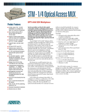
ADTRAN OPTI-6100 LMX Specification Sheet (2 pages)
STM - 1/4 Optical Access MUX
Brand: ADTRAN
|
Category: Multiplexer
|
Size: 0.77 MB
Advertisement
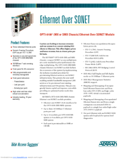
ADTRAN OPTI-6100 LMX Specification Sheet (2 pages)
Ethernet Over SONET Module
Brand: ADTRAN
|
Category: Network Card
|
Size: 0.53 MB

ADTRAN OPTI-6100 LMX Specifications (2 pages)
OPTI-6100 Multi-Service Provisioning Platform
Advertisement