Table of Contents
Advertisement
Quick Links
Class A Power Quality
Instrument and
Power Monitoring Device
SICAM Q100
7KG95xx
V2.10
Device Manual
E50417-H1040-C522-A6
Preface
Open Source Software
Contents
User Information
Overview
Device Design
Measured Quantities and Recording
Energy Management
Security
Getting Started
Connection Principle
Operation at Use of a PC
Operation at Use of the Display
Time Synchronization
Maintenance, Storage, Transport
Failures and LED Indications
Technical Data
Operational Indications
Operating Parameters
Glossary
Appendix
Index
1
2
3
4
5
6
7
8
9
10
11
12
13
14
15
16
Advertisement
Table of Contents

Related Manuals for Siemens SICAM Q100 7KG95 Series


Summary of Contents for Siemens SICAM Q100 7KG95 Series
- Page 1 Preface Open Source Software Contents User Information Class A Power Quality Overview Instrument and Power Monitoring Device Device Design Measured Quantities and Recording SICAM Q100 Energy Management 7KG95xx Security V2.10 Getting Started Connection Principle Device Manual Operation at Use of a PC Operation at Use of the Display Time Synchronization Maintenance, Storage, Transport...
- Page 2 SIEMENS AG. An unauthorized use is illegal. Siemens AG reserves the right to revise this document from time to All other designations in this document can be trademarks whose time.
-
Page 3: Preface
This manual is valid for the Class A Power Quality Instrument and Power Monitoring Device SICAM Q100 7KG95xx. Further Support For any questions concerning your system, please contact your Siemens representative. The Siemens Customer Support Center provides around-the-clock support. Phone:... - Page 4 Notes On Safety This manual is not a complete index of all safety measures required for operation of the equipment (module, device). However, it comprises important information that must be noted for purposes of personal safety, as well as in order to avoid material damage. Information is highlighted and illustrated as follows according to the degree of danger.
- Page 5 Technical Description. If it is used together with third-party devices and components, these must be recommended or approved by Siemens. If the device is not used in accordance with the Product Information and this manual, the scheduled protection is impaired.
- Page 6 Used Symbols Symbol Description Direct current IEC 60417-5031 Alternating current IEC 60417-5032 Direct and alternating current IEC 60417-5033 Three-phase alternating current Earth (ground) terminal IEC 60417-5017 Protective conductor terminal IEC 60417-5019 Caution, risk of electric shock Caution, risk of danger ISO 7000-0434 Guideline 2002/96/EC for electrical and electronic devices...
- Page 7 (Lowvoltage Directive 2006/95/EC - valid until April 19th, 2016; Lowvoltage Directive 2014/35/ EU - valid as of April 20th, 2016). This conformity has been established by means of tests conducted by Siemens AG according to the Council Directive in agreement with the generic standards EN 61000-6-2 and EN 61000-6-4 for the EMC directives, and with the standard EN 61010-1 for the low-voltage directive.
- Page 8 SICAM Q100, 7KG95xx, Device Manual E50417-H1040-C522-A6, Edition 06.2019...
-
Page 9: Open Source Software
The Open Source Software is licensed royalty-free. Insofar as the applicable Open Source Software License Conditions provide for it, you can order the source code of the Open Source Software from your Siemens sales contact - against payment of the shipping and handling charges - for a period of at least 3 years since purchase of the Product. - Page 10 SICAM Q100, 7KG95xx, Device Manual E50417-H1040-C522-A6, Edition 06.2019...
-
Page 11: Table Of Contents
Contents Preface ................. . 3 Open Source Software . - Page 12 Account Management ............. 96 6.2.1 Function Description.
- Page 13 Start and Design of the User Interface ..........139 9.2.1 Initial Start of the Operation .
- Page 14 Time Synchronization..............361 11.1 General .
- Page 15 16.3 HMI ................407 16.3.1 Display Settings .
- Page 16 SICAM Q100, 7KG95xx, Device Manual E50417-H1040-C522-A6, Edition 06.2019...
-
Page 17: User Information
1 User Information User Information Application The SICAM Q100 is a multifunctional device for the detection, processing, and evaluation of measured quan- tities and events according to IEC 61000-4-30, class A, power quality (PQ) standard. The energy management functions also allow determining load profiles and setting up to 8 tariffs. The device is used on all voltage levels of power supply systems. - Page 18 1 User Information Functionality of the Recorders The recorders can record measured quantities, events, and load profiles in parameterizable time intervals. The following recorder types are used: • Measurement recorder: recording of PQ measured quantities acc. to IEC 61000-4-30 (for example, frequency, voltage magnitude) and non-PQ measured quantities (for example, currents, power) over parameterized periods, for example, 10-second frequency, aggregation of voltage, current, power.
-
Page 19: Overview
2 Overview Overview Device Versions Ordering Information, Scope of Delivery and Accessories SICAM Q100, 7KG95xx, Device Manual E50417-H1040-C522-A6, Edition 06.2019... -
Page 20: Device Versions
2 Overview 2.1 Device Versions Device Versions SICAM Q100 is a multifunctional device for the detection, calculation, recording, evaluation, display, and trans- mission of measured electrical quantities with the following properties: Consistent Device Properties All devices consistently feature the following properties: •... - Page 21 2 Overview 2.1 Device Versions • Internal Ethernet switch • Certificates CE certification UL certification • Evaluations Output of power quality reports Variants SICAM Q100 is available in different variants: • Communication via Ethernet Only Modbus TCP protocol ...
-
Page 22: Ordering Information, Scope Of Delivery And Accessories
2 Overview 2.2 Ordering Information, Scope of Delivery and Accessories Ordering Information, Scope of Delivery and Accessories Ordering Information Use the following ordering code to order SICAM Q100 devices: Description Order No. / MLFB Power Monitoring Device and Power Quality Recorder, Class A 1 2 3 10 11 12 13 14 15 16... - Page 23 • Product Information Accessories You can order the following accessories: • Device Manual E50417-H1040-C522 (download available at https://www.siemens.com/powerquality) • RS485 bus terminating plug 220 W in a 9-pin D-sub connector plug: 7XV5103-5AA00 • Connectors for alternating voltage inputs Order via: Phoenix Contact GmbH &...
- Page 24 2 Overview 2.2 Ordering Information, Scope of Delivery and Accessories Table 2-3 Ethernet Patch Cable (Double Shielded (SFPT), LAN Connector Plugs on Both Sides) Cable Length Order No. 0.5 m 7KE6000-8G-D00-0AA5 1.0 m 7KE6000-8G-D00-1AA0 2.0 m 7KE6000-8G-D00-2AA0 3.0 m 7KE6000-8G-D00-3AA0 5.0 m 7KE6000-8G-D00-5AA0 10.0 m...
-
Page 25: Device Design
3 Device Design Device Design Mechanical Design Display and Softkeys Terminal Diagram of the Back Plate SICAM Q100, 7KG95xx, Device Manual E50417-H1040-C522-A6, Edition 06.2019... -
Page 26: Mechanical Design
3 Device Design 3.1 Mechanical Design Mechanical Design The device is designed for panel flush mounting. The electrical modules are installed in a plastic case with the dimensions 96 mm x 96 mm x 100 mm (W x H x D). The display side of the device contains the display, 4 softkeys located below and 4 LEDs of which the H1, H2, and ERROR LEDs can be parameterized. -
Page 27: Display And Softkeys
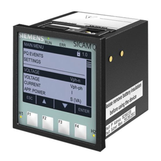
3 Device Design 3.2 Display and Softkeys Display and Softkeys Display The layout of the display is shown in the following figure. Title Display area Softkey functions Softkeys F1 to F4 Figure 3-2 Display and Softkeys The top line (title) shows the name of the current display in the display area. The display area below shows parameter settings, measured values, and graphic pictures. -
Page 28: Terminal Diagram Of The Back Plate
3 Device Design 3.3 Terminal Diagram of the Back Plate Terminal Diagram of the Back Plate Figure 3-3 Terminal Diagram of the Back Plate SICAM Q100, 7KG95xx, Device Manual E50417-H1040-C522-A6, Edition 06.2019... -
Page 29: Measured Quantities And Recording
4 Measured Quantities and Recording Measured Quantities and Recording Power Quality Measuring System and Recording System Measured Quantities Display of Measured Quantities SICAM Q100, 7KG95xx, Device Manual E50417-H1040-C522-A6, Edition 06.2019... -
Page 30: Power Quality Measuring System And Recording System
4 Measured Quantities and Recording 4.1 Power Quality Measuring System and Recording System Power Quality Measuring System and Recording System 4.1.1 Measuring System SICAM Q100 devices measure the power quality according to IEC 61000-4-30 in 1-phase or multi-phase distribution systems. The basic measuring interval for determining the values for mains voltage, harmonics of mains voltage, and mains voltage unbalance is 10 cycles for 50-Hz distribution systems or 12 cycles for 60-Hz distribution systems. -
Page 31: Transients
4 Measured Quantities and Recording 4.1 Power Quality Measuring System and Recording System 4.1.3 Transients If the instantaneous value of the primary rated voltage exceeds the parameterized reference value at one or several sampling points, the SICAM Q100 device detects temporary overvoltages as transients . Detect and capture transients as short as 100 µs at 50 Hz (80 µs at 60 Hz). -
Page 32: Mains Signaling Voltage
4 Measured Quantities and Recording 4.1 Power Quality Measuring System and Recording System Figure 4-1 Transient Detection 4.1.4 Mains Signaling Voltage Mains signaling voltage (MSV) measurement is performed according to IEC 61000-4-30. SICAM Q100, 7KG95xx, Device Manual E50417-H1040-C522-A6, Edition 06.2019... - Page 33 4 Measured Quantities and Recording 4.1 Power Quality Measuring System and Recording System SICAM Q100 detects mains singalling frequencies from 100 Hz to 3 kHz. The threshold for detection and capture is from 1 % up to 15 % of Udin. The following data and values are determined during the evaluation of the mains signaling voltage in SICAM Q100 and listed in the window Mains signaling voltage (see chapter 9.4.2.3): •...
-
Page 34: Rapid Voltage Change
4 Measured Quantities and Recording 4.1 Power Quality Measuring System and Recording System 4.1.5 Rapid Voltage Change Rapid voltage change (RVC) is a quick transition of RMS voltage occurring between two steady-state conditions, and during which the RMS voltage does not exceed the dip/swell threshold. The threshold of RVC detection is configurable from 1 % up to 6 % of Udin. -
Page 35: Harmonic Power And Harmonic Angles
4 Measured Quantities and Recording 4.1 Power Quality Measuring System and Recording System 4.1.6 Harmonic Power and Harmonic Angles Measurement of phase angles is helpful to analyze different phenomena. The measurement can be used for the following purposes: • Evaluation of harmonic flows throughout the system •... - Page 36 The prevailing ratio (PR) is proposed to indicate how much the harmonic measurements vary in the complex plane. NOTE You find further information to this feature in the application note: www.siemens.com/powerquality. SICAM Q100, 7KG95xx, Device Manual E50417-H1040-C522-A6, Edition 06.2019...
-
Page 37: Recording Of Measured Quantities And Events
4 Measured Quantities and Recording 4.1 Power Quality Measuring System and Recording System 4.1.7 Recording of Measured Quantities and Events 4.1.7.1 Power Quality Recorder Types SICAM Q100 provides different recording options to monitor and analyze the power quality and for the load profile. - Page 38 4 Measured Quantities and Recording 4.1 Power Quality Measuring System and Recording System Table 4-2 Recording Measured Values (cont.) Storage interval/storage Measured quantity Application Recording method Voltage/current/binary Voltages, variation triggers, Analyzing the causes of Fault recorder Currents, acquisition of sampled values power quality problems Binary (max.
- Page 39 4 Measured Quantities and Recording 4.1 Power Quality Measuring System and Recording System The interaction of the recorders is depicted in the following figure: V(t) Measurement Pst, Plt Flicker meter Recorder V(t) A/ D Converter I (t) Frequency Measurement Recorder Event PQ events: Interruptions , Swells...
-
Page 40: Measured Quantities
4 Measured Quantities and Recording 4.2 Measured Quantities Measured Quantities 4.2.1 Measured Quantities Depending on the Connection Type 4.2.1.1 Operational Measured Quantities and Connection Types Table 4-3 Operational Measured Quantities, Connection Types in Power Systems 3-Wire Network 4-Wire Network (Delta) (Star) PQ Values for PQ Values for... - Page 41 4 Measured Quantities and Recording 4.2 Measured Quantities Table 4-3 Operational Measured Quantities, Connection Types in Power Systems (cont.) 3-Wire Network 4-Wire Network (Delta) (Star) PQ Values for PQ Values for ph-N ph-ph Measured 1-phase Circuit Quantity System Alternating Current a, b, c ...
- Page 42 4 Measured Quantities and Recording 4.2 Measured Quantities Table 4-3 Operational Measured Quantities, Connection Types in Power Systems (cont.) 3-Wire Network 4-Wire Network (Delta) (Star) PQ Values for PQ Values for ph-N ph-ph Measured 1-phase Circuit Quantity System UIb UIc UI ...
- Page 43 4 Measured Quantities and Recording 4.2 Measured Quantities 4.2.1.2 Harmonics/Interharmonics, Connection Types Table 4-4 Harmonics/Interharmonics, Connection Types in Power Systems 3-Wire Network 4-Wire Network (Delta) (Star) PQ Values for PQ Values for ph-N ph-ph Measured Quantity (x = 1 to 63, 1-phase y = 1 to 49) Circuit...
- Page 44 4 Measured Quantities and Recording 4.2 Measured Quantities Table 4-4 Harmonics/Interharmonics, Connection Types in Power Systems (cont.) 3-Wire Network 4-Wire Network (Delta) (Star) PQ Values for PQ Values for Measured ph-N ph-ph Quantity (x = 1 to 63, 1-phase y = 1 to 49) Circuit System x = 1:...
- Page 45 4 Measured Quantities and Recording 4.2 Measured Quantities Table 4-4 Harmonics/Interharmonics, Connection Types in Power Systems (cont.) 3-Wire Network 4-Wire Network (Delta) (Star) PQ Values for PQ Values for Measured ph-N ph-ph Quantity (x = 1 to 63, 1-phase y = 1 to 49) Circuit System x = 1:...
- Page 46 4 Measured Quantities and Recording 4.2 Measured Quantities Table 4-4 Harmonics/Interharmonics, Connection Types in Power Systems (cont.) 3-Wire Network 4-Wire Network (Delta) (Star) PQ Values for PQ Values for Measured ph-N ph-ph Quantity (x = 1 to 63, 1-phase y = 1 to 49) Circuit System x = 1:...
- Page 47 4 Measured Quantities and Recording 4.2 Measured Quantities Table 4-4 Harmonics/Interharmonics, Connection Types in Power Systems (cont.) 3-Wire Network 4-Wire Network (Delta) (Star) PQ Values for PQ Values for Measured ph-N ph-ph Quantity (x = 1 to 63, 1-phase y = 1 to 49) Circuit System x = 1:...
- Page 48 4 Measured Quantities and Recording 4.2 Measured Quantities 4.2.1.3 Measured Quantities of Power, Connection Types Table 4-5 Measured Quantities of Power, Connection Types in Power Systems 3-Wire Network 4-Wire Network (Delta) (Star) PQ Values for PQ Values for ph-N ph-ph Measured 1-phase Circuit...
- Page 49 4 Measured Quantities and Recording 4.2 Measured Quantities Table 4-5 Measured Quantities of Power, Connection Types in Power Systems 3-Wire Network 4-Wire Network (Delta) (Star) PQ Values for PQ Values for ph-N ph-ph Measured 1-phase Circuit Quantity System Q1ph a, b, c SICAM Q100, 7KG95xx, Device Manual E50417-H1040-C522-A6, Edition 06.2019...
- Page 50 4 Measured Quantities and Recording 4.2 Measured Quantities 4.2.1.4 Measured Quantities of Energy, Connection Types Table 4-6 Measured Quantities of Energy, Connection Types in Power Systems 3-Wire Network 4-Wire Network (Delta) (Star) PQ Values for PQ Values for ph-N ph-ph Measured 1-phase Circuit...
- Page 51 4 Measured Quantities and Recording 4.2 Measured Quantities Table 4-6 Measured Quantities of Energy, Connection Types in Power Systems (cont.) 3-Wire Network 4-Wire Network (Delta) (Star) PQ Values for PQ Values for ph-N ph-ph Measured 1-phase Circuit System Quantity WQa_cap WQb_cap WQc_cap WQ_cap...
- Page 52 4 Measured Quantities and Recording 4.2 Measured Quantities Table 4-6 Measured Quantities of Energy, Connection Types in Power Systems (cont.) 3-Wire Network 4-Wire Network (Delta) (Star) PQ Values for PQ Values for ph-N ph-ph Measured 1-phase Circuit System Quantity WPc_imp WP_imp a, b, c Freeze Reactive Energy - Inductive...
- Page 53 4 Measured Quantities and Recording 4.2 Measured Quantities Use 10/12 cycles RMS value for calculation. 4.2.1.5 Flicker, MSV, and Connection Types Table 4-7 Flicker, MSV, and Connection Types in Power Systems 3-Wire Network 4-Wire Network (Delta) (Star) PQ Values for PQ Values for ph-N ph-ph...
- Page 54 4 Measured Quantities and Recording 4.2 Measured Quantities Table 4-7 Flicker, MSV, and Connection Types in Power Systems (cont.) 3-Wire Network 4-Wire Network (Delta) (Star) PQ Values for PQ Values for ph-N ph-ph Measured 1-phase Circuit Quantity System Pinst-ab Pinst-bc Pinst-ca Main Signaling Voltage (MSV) Msv_a-N...
- Page 55 4 Measured Quantities and Recording 4.2 Measured Quantities 4.2.1.6 Measured Quantities of Harmonics Power, Connection Types Table 4-8 Measurements of Harmonics Power, Connection Types in Power Systems 3-Wire Network 4-Wire Network (Delta) (Star) PQ Values for PQ Values for ph-N ph-ph Measured Quantity...
- Page 56 4 Measured Quantities and Recording 4.2 Measured Quantities Table 4-8 Measurements of Harmonics Power, Connection Types in Power Systems 3-Wire Network 4-Wire Network (Delta) (Star) PQ Values for PQ Values for ph-N ph-ph Measured Quantity 1-phase (x = 1 to 63) Circuit System x1 =...
-
Page 57: Data Availability Of Measured Quantities
4 Measured Quantities and Recording 4.2 Measured Quantities 4.2.2 Data Availability of Measured Quantities 4.2.2.1 Data Availability of the Operational Measured Quantities Table 4-9 Data Availability of the Operational Measured Quantities Operational Measured Quantities Limit violation HTML and Display Protocol/Interface Measured Modbus TCP, Modbus RTU, Quantity... - Page 58 4 Measured Quantities and Recording 4.2 Measured Quantities Table 4-9 Data Availability of the Operational Measured Quantities (cont.) Operational Measured Quantities Limit violation HTML and Display Protocol/Interface Measured Modbus TCP, Modbus RTU, Quantity IEC 61850 10/12 cycles 10/12 cycles 10/12 cycles 150/180 cycles 150/180 cycles 150/180 cycles...
- Page 59 4 Measured Quantities and Recording 4.2 Measured Quantities Table 4-9 Data Availability of the Operational Measured Quantities (cont.) Operational Measured Quantities Limit violation HTML and Display Protocol/Interface Measured Modbus TCP, Modbus RTU, Quantity IEC 61850 10/12 cycles 10/12 cycles 10/12 cycles 150/180 cycles 150/180 cycles 150/180 cycles...
- Page 60 4 Measured Quantities and Recording 4.2 Measured Quantities Table 4-10 Data Availability of the Harmonics/Interharmonics (cont.) Operational Measured Quantities Limit violation HTML and Display Protocol/Interface Measured Quantity Modbus TCP, Modbus RTU, (x = 1 to 63, IEC 61850 y = 1 to 49) 10/12 cycles 10/12 cycles 10/12 cycles...
- Page 61 4 Measured Quantities and Recording 4.2 Measured Quantities Table 4-10 Data Availability of the Harmonics/Interharmonics (cont.) Operational Measured Quantities Limit violation HTML and Display Protocol/Interface Measured Quantity Modbus TCP, Modbus RTU, (x = 1 to 63, IEC 61850 y = 1 to 49) 10/12 cycles 10/12 cycles 10/12 cycles...
- Page 62 4 Measured Quantities and Recording 4.2 Measured Quantities Table 4-10 Data Availability of the Harmonics/Interharmonics (cont.) Operational Measured Quantities Limit violation HTML and Display Protocol/Interface Measured Quantity Modbus TCP, Modbus RTU, (x = 1 to 63, IEC 61850 y = 1 to 49) 10/12 cycles 10/12 cycles 10/12 cycles...
- Page 63 4 Measured Quantities and Recording 4.2 Measured Quantities Table 4-10 Data Availability of the Harmonics/Interharmonics (cont.) Operational Measured Quantities Limit violation HTML and Display Protocol/Interface Measured Quantity Modbus TCP, Modbus RTU, (x = 1 to 63, IEC 61850 y = 1 to 49) 10/12 cycles 10/12 cycles 10/12 cycles...
- Page 64 4 Measured Quantities and Recording 4.2 Measured Quantities Table 4-10 Data Availability of the Harmonics/Interharmonics (cont.) Operational Measured Quantities Limit violation HTML and Display Protocol/Interface Measured Quantity Modbus TCP, Modbus RTU, (x = 1 to 63, IEC 61850 y = 1 to 49) 10/12 cycles 10/12 cycles 10/12 cycles...
- Page 65 4 Measured Quantities and Recording 4.2 Measured Quantities 4.2.2.3 Data Availability of the Measured Quantities of Power Table 4-11 Data Availability of the Measured Quantities of Power Operational Measured Quantities Limit violation HTML and Display Protocol/Interface Modbus TCP, Modbus RTU, Measured Quantity IEC 61850 10/12 cycles...
- Page 66 4 Measured Quantities and Recording 4.2 Measured Quantities 4.2.2.4 Data Availability of the Measured Quantities of Energy Table 4-12 Data Availability of the Measured Quantities of Energy Operational Measured Quantities Limit violation HTML and Display Protocol/Interface Measured Quantity Modbus TCP, Modbus RTU, IEC 61850 10/12 cycles 10/12 cycles...
- Page 67 4 Measured Quantities and Recording 4.2 Measured Quantities Table 4-12 Data Availability of the Measured Quantities of Energy (cont.) Operational Measured Quantities Limit violation HTML and Display Protocol/Interface Measured Quantity Modbus TCP, Modbus RTU, IEC 61850 10/12 cycles 10/12 cycles 10/12 cycles Apparent Energy Freeze Active Energy –...
- Page 68 4 Measured Quantities and Recording 4.2 Measured Quantities Table 4-12 Data Availability of the Measured Quantities of Energy (cont.) Operational Measured Quantities Limit violation HTML and Display Protocol/Interface Measured Quantity Modbus TCP, Modbus RTU, IEC 61850 10/12 cycles 10/12 cycles 10/12 cycles WQa_cap HTML...
- Page 69 4 Measured Quantities and Recording 4.2 Measured Quantities Table 4-13 Data Availability of the Flicker (cont.) Operational Measured Quantities Limit violation HTML and Display Protocol/Interface Measured Quantity Modbus TCP, Modbus RTU, IEC 61850 10/12 cycles 10/12 cycles 10/12 cycles Pst_c-N Pst_ab Pst_bc Pst_ca...
- Page 70 4 Measured Quantities and Recording 4.2 Measured Quantities 4.2.2.6 Data Availability of the Measured Quantities of Harmonics Power Table 4-14 Data Availability of the Measured Quantities of Harmonics Power Operational Measured Quantities Measured Quantity Limit violation HTML and Display Protocol/Interface (x = 1 to 63) Modbus TCP, Modbus RTU, x1 = Fundamental...
-
Page 71: Recording And Evaluation Of Measured Quantities
4 Measured Quantities and Recording 4.2 Measured Quantities 4.2.3 Recording and Evaluation of Measured Quantities 4.2.3.1 Recording and Evaluation of the Operational Measured Quantities Table 4-15 Recording and Evaluation of the Operational Measured Quantities Event Mains Measurement Recorder Recorder Trend Fault Signaling Recorder... - Page 72 4 Measured Quantities and Recording 4.2 Measured Quantities Table 4-15 Recording and Evaluation of the Operational Measured Quantities (cont.) Event Mains Measurement Recorder Recorder Trend Fault Signaling Recorder Voltage Recorder Measured Max. Min. Recorder Quantity Value Value Values PQDIF, CSV PQDIF COMTRADE COMTRADE...
- Page 73 4 Measured Quantities and Recording 4.2 Measured Quantities Table 4-15 Recording and Evaluation of the Operational Measured Quantities (cont.) Event Mains Measurement Recorder Recorder Trend Fault Signaling Recorder Voltage Recorder Measured Max. Min. Recorder Quantity Value Value Values PQDIF, CSV PQDIF COMTRADE COMTRADE...
- Page 74 4 Measured Quantities and Recording 4.2 Measured Quantities 4.2.3.2 Recording and Evaluation of the Harmonics/Interharmonics Table 4-16 Recording and Evaluation of the Harmonics/Interharmonics Measurement Recorder Measured Quantity (x = 1 to 49, y = 1 to 49) Max. Value Min. Value x = 1: Fundamental PQDIF, CSV Harmonics, Voltage, Magnitude...
- Page 75 4 Measured Quantities and Recording 4.2 Measured Quantities Table 4-16 Recording and Evaluation of the Harmonics/Interharmonics (cont.) Measurement Recorder Measured Quantity (x = 1 to 49, y = 1 to 49) Max. Value Min. Value x = 1: Fundamental PQDIF, CSV HI_Ic-y THDS, Voltage THDS_Va...
- Page 76 4 Measured Quantities and Recording 4.2 Measured Quantities 4.2.3.3 Recording and Evaluation of the Power Types Table 4-17 Recording and Evaluation of the Power Types Measurement Recorder Max. Value Min. Value Measured Quantity PQDIF, CSV Active Power Reactive Power Apparent Power Reactive Power (Fundamental) Interfaces: protocols IEC 61850 (PQDIF depending on the measuring interval) and Modbus TCP;...
- Page 77 4 Measured Quantities and Recording 4.2 Measured Quantities 4.2.3.4 Recording and Evaluation of the Measured Quantities of Energy The recording and evaluation of the energy types is described in detail in 5 Energy Management. 4.2.3.5 Recording and Evaluation of the Flicker Table 4-18 Recording and Evaluation of the Flicker Measurement Recorder...
-
Page 78: Display Of Measured Quantities
4 Measured Quantities and Recording 4.3 Display of Measured Quantities Display of Measured Quantities 4.3.1 Measured Quantities and Operational Measurement Uncertainty acc. to IEC 62586-1 Product Standard, Class A, Standards IEC 61000-4-30, Ed. 3, IEC 61000-4-7, and IEC 61000-4-15 Table 4-19 Measured Quantities and their Operational Measurement Uncertainty Operat. - Page 79 4 Measured Quantities and Recording 4.3 Display of Measured Quantities Table 4-19 Measured Quantities and their Operational Measurement Uncertainty (cont.) Operat. Measurem. Uncertainty acc. to IEC 62586-1, Class A, Measured Quantity Unit Measurement Range IEC 61000-4-30, IEC 61000-4-7, and IEC 61000-4-15 IEC 61000-4-7, class 1: Condition: V >...
-
Page 80: Measured Quantities And Operational Measurement Accuracy Acc. To Iec 61557-12
4 Measured Quantities and Recording 4.3 Display of Measured Quantities 4.3.2 Measured Quantities and Operational Measurement Accuracy acc. to IEC 61557-12 Table 4-20 Measured Quantities and their Operational Measurement Accuracy Measurement Measured Quantity Unit Rated Value Accuracy Class Range Current I Auto range (1 A 10 % to 200 % I rated... -
Page 81: Accuracy Of The Frequency Measurement
4 Measured Quantities and Recording 4.3 Display of Measured Quantities 4.3.3 Accuracy of the Frequency Measurement Table 4-21 Accuracy of the Frequency Measurement Circuit Accuracy Voltage to V 0 V to 2 V: invalid > 2 V: 10 mHz Voltage to V Voltage to V NOTE The frequency measurement is carried out as software frequency measurement (V... - Page 82 4 Measured Quantities and Recording 4.3 Display of Measured Quantities SICAM Q100, 7KG95xx, Device Manual E50417-H1040-C522-A6, Edition 06.2019...
-
Page 83: Energy Management
5 Energy Management Energy Management Load-Profile Determination Tariffs SICAM Q100, 7KG95xx, Device Manual E50417-H1040-C522-A6, Edition 06.2019... -
Page 84: Load-Profile Determination
5 Energy Management 5.1 Load-Profile Determination Load-Profile Determination 5.1.1 General The load profile reflects the history of the electric power and documents the distribution of power fluctuations and peaks. The load profile is determined on subperiods of 10/12 cycles (50 Hz/60 Hz). SICAM Q100 supports 2 methods of load-profile determination: the Fixed Block method and the Rolling Block method. -
Page 85: Methods Of Load-Profile Determination
5 Energy Management 5.1 Load-Profile Determination 5.1.2 Methods of Load-Profile Determination NOTE The parameterization of the load profile is described in detail in chapter 8.3.5.1. Note the information specified there. SICAM Q100 supports the following load-profile determination methods: • Fixed Block •... - Page 86 5 Energy Management 5.1 Load-Profile Determination Rolling Block Method A measuring period of the Rolling Block method consists of 2 to 5 subperiods depending on the parameter- ization. The length of a measuring period is the product of the number of subperiods and the parameterized length of the subperiod;...
-
Page 87: Historical Load-Profile Data
5 Energy Management 5.1 Load-Profile Determination Load-Profile Calculation Arithmetic average power value The calculation of the arithmetic average power value of a measuring period refers to the actual duration of the measuring period. Special case: With constant power consumption or constant power supply, the arithmetic average power value also remains constant in the current measuring period. -
Page 88: Current Load-Profile Data At The Communication Interfaces And In The User Interface
5 Energy Management 5.1 Load-Profile Determination 5.1.4 Current Load-Profile Data at the Communication Interfaces and in the User Interface The load-profile data of the current and last completed periods are output at the communication interfaces. For information on the data transmission via the communication protocols Modbus TCP, Modbus RTU Master, and IEC 61850, refer to the System Manual SICAM Q100. -
Page 89: Synchronization Of The Load Profile
5 Energy Management 5.1 Load-Profile Determination 5.1.5 Synchronization of the Load Profile 5.1.5.1 Types of Synchronization At the beginning of every subperiod, SICAM Q100 expects a synchronization signal which can either be sup- plied externally or created internally. External supply of the synchronization signal: •... - Page 90 5 Energy Management 5.1 Load-Profile Determination 5.1.5.2 Special Conditions and Effects on the Load Profile Device Restart If a functional battery is installed in SICAM Q100, the existing load-profile records are kept unchanged. Resetting the Device Clock Resetting the device clock does not affect the load-profile recording. The historical load profiles with a date in the future do not prevent resetting the device clock.
-
Page 91: Tariffs
5 Energy Management 5.2 Tariffs Tariffs NOTE The parameterization of the tariffs is described in detail in chapter 9.3.5.2. Note the information specified there. SICAM Q100 supports up to 8 tariffs for power meters for supplied or consumed active energy, reactive energy, and apparent energy. - Page 92 5 Energy Management 5.2 Tariffs SICAM Q100, 7KG95xx, Device Manual E50417-H1040-C522-A6, Edition 06.2019...
-
Page 93: Security
6 Security Security Overview Account Management Security Settings Password Management TCP/UDP Ports Used SICAM Q100, 7KG95xx, Device Manual E50417-H1040-C522-A6, Edition 06.2019... -
Page 94: Overview
Q100 user interface, all browsers will show a message regarding an unknown certificate warning about an untrusted connection. Due to the au- thentication scheme used by browsers, Siemens cannot provide certifi- cates (for example, during assembly) to be used for HTTPS with browsers. - Page 95 For more detailed information, refer to chapter 9.3.7.2.1. Deploy in a Secured Environment Only Siemens recommends protecting network access to its energy automation products with appropriate mecha- nisms (for example, firewalls, segmentation, VPN). It is advised to configure the environment according to the operational guidelines in order to run the devices in a protected IT environment.
-
Page 96: Account Management
6 Security 6.2 Account Management Account Management 6.2.1 Function Description The SICAM Q100 device provides a role-based access control (RBAC) mechanism for account management. This function is a policy-neutral mechanism for access control to define the roles and privileges. With the RBAC mechanism, the permissions to perform certain actions on the SICAM Q100 device are assigned to specific roles. - Page 97 6 Security 6.2 Account Management Table 6-2 Access Rights Assigned to Different Roles Role Access to the Web UI Tabs Information Configure Maintenance Value View Evaluation Guest View all Password management pages Viewer • View all operational settings View all View operational log, error logs, pages and diagnosis data...
-
Page 98: Configuration Via User Interface
6 Security 6.2 Account Management NOTE Only a user with the role of administrator, security administrator, or user account manager has the permission to access the Account management. HMI Password The SICAM Q100 device provides an option to use an HMI password. It determines whether the password for actions at the device display is activated or deactivated. - Page 99 6 Security 6.2 Account Management ✧ Enter a new user name and password according to the following table: Table 6-3 Settings for Creating an Initial Account Settings Default Settings Description Account Type Administrator User Account Manager Administrator User name Empty Up to 64 characters New password Empty...
- Page 100 6 Security 6.2 Account Management ✧ Enter the created user name and password in the Log on tab. Figure 6-3 Log on Tab, Account Management ✧ Click Log on. The Information tab appears if the entered user name and password are correct. Creating User Accounts with Different Roles Figure 6-4 Creating Accounts...
- Page 101 6 Security 6.2 Account Management ✧ Create user accounts according to the following tables: Table 6-4 Settings for Creating User Accounts Settings Default Settings Description User name Empty Up to 64 characters New password 8 to 24 characters Contains at least: Repeat new password •...
- Page 102 6 Security 6.2 Account Management x represents that the user with this role is assigned with related rights. ✧ Enter the user name, the password, and select a role or several roles for a user account. ✧ Click Confirm. A user account is created. Editing or Deleting an Existing User Account Figure 6-6 Editing or Deleting a User Account...
- Page 103 6 Security 6.2 Account Management ✧ Edit the user account according to the following table: Table 6-6 Settings for Editing a User Account Settings Default Settings Description User name Empty Up to 64 characters New password 8 to 24 characters Contains at least: Repeat new password •...
- Page 104 6 Security 6.2 Account Management Setting the HMI Password Figure 6-8 Configuration Tab, HMI Password To set the HMI password in the Configure tab, proceed as follows: ✧ In the navigation window, select Administrative and click Account management. ✧ Set the HMI password according to the following table: Table 6-7 Settings for the HMI Password Settings...
-
Page 105: Security Settings
6 Security 6.3 Security Settings Security Settings 6.3.1 Function Description The SICAM Q100 device provides the security settings to configure the logon settings. NOTE Only a user with the role of administrator or security administrator has the permission to access Security Settings. - Page 106 6 Security 6.3 Security Settings ✧ Configure the respective parameters according to the following table: Table 6-8 Settings for the Security Parameter Default Setting Setting Ranges Maximum consecutive attempts 5 times to 12 times 1 min to 10 min Consecutive password attempt time period Logon block timeout 30 min to 360 min...
-
Page 107: Password Management
6 Security 6.4 Password Management Password Management 6.4.1 Function Description To change the Web UI login password, the SICAM Q100 device provides the access to Password Manage- ment. 6.4.2 Configuration via the User Interface Figure 6-10 Changing Passwords, Password Management To change the password in the Configure tab, proceed as follows: ✧... - Page 108 6 Security 6.4 Password Management ✧ Enter the new password. ✧ Click Confirm. The password is changed. SICAM Q100, 7KG95xx, Device Manual E50417-H1040-C522-A6, Edition 06.2019...
-
Page 109: Tcp/Udp Ports Used
6 Security 6.5 TCP/UDP Ports Used TCP/UDP Ports Used The following table contains an overview of the TCP/UDP ports used. Table 6-10 Overview Communication Server/ TCP/ Port Activated Description Protocol Client by Default HTTPS Server TLS connection to a Web browser for device configuration and value view Client... - Page 110 6 Security 6.5 TCP/UDP Ports Used SICAM Q100, 7KG95xx, Device Manual E50417-H1040-C522-A6, Edition 06.2019...
-
Page 111: Getting Started
7 Getting Started Getting Started Unpacking, Inspecting the Delivery, Installing, and Changing the Battery Assembly Electrical Connection System Requirements Access Rights Meaning of the LEDs Commissioning SICAM Q100, 7KG95xx, Device Manual E50417-H1040-C522-A6, Edition 06.2019... -
Page 112: Unpacking, Inspecting The Delivery, Installing, And Changing The Battery
7 Getting Started 7.1 Unpacking, Inspecting the Delivery, Installing, and Changing the Battery Unpacking, Inspecting the Delivery, Installing, and Changing the Battery Unpacking The SICAM Q100 has been safely packed for transport in the factory. Unpack the device with care and do not use force. - Page 113 7 Getting Started 7.1 Unpacking, Inspecting the Delivery, Installing, and Changing the Battery ✧ Take the wrapped battery out of the battery compartment. ✧ Remove the plastic foil from the battery. ✧ Insert the battery into the battery compartment with the polarity imprinted on the top side of the device (see Figure 7-1).
-
Page 114: Assembly
7 Getting Started 7.2 Assembly ✧ Press the cover of the battery compartment back into the housing and make sure it is in the correct position. NOTE on Battery Disposal The battery used in this device contains lithium. It may only be replaced by qualified personnel and disposed of by authorized recycling companies. -
Page 115: Environmental Protection Hints
When disposing of or transferring a mobile storage device, Siemens strongly recommends physically destroying it or completely deleting data from the mobile storage device by using a commercially available computer data eras- ing software. -
Page 116: Assembly
7 Getting Started 7.2 Assembly 7.2.3 Assembly To install the device into a switch panel, proceed as follows: ✧ Push the device in installation position into the cut-out of the switch panel and hold the device tight. ✧ Attach one of the supplied mounting elements each on both sides of the housing. Mounting plate Mounting element ... -
Page 117: Electrical Connection
✧ Check the polarity and the phase assignment at the instrument transformers. Siemens recommends leaving the device for a minimum of 2 hours in the operating room, before using it to allow temperature equalization and to avoid dimness and condensation. -
Page 118: Electrical Connection Of Sicam Q100
7 Getting Started 7.3 Electrical Connection 7.3.2 Electrical Connection of SICAM Q100 Terminal connection of the supply voltage Figure 7-3 Terminal Connection of the Supply Voltage at the SICAM Q100 DANGER Hazard due to high voltage Non-observance will lead to death or serious injury. Work may only be carried out by trained personnel (see Preface) who are familiar with and observe the safety requirements and precautions. -
Page 119: System Requirements
7 Getting Started 7.4 System Requirements Connect the cables of the supply voltage on the terminal side of the device at terminal block H as follows: Supply from the Alternating Voltage System Terminal N/-: Neutral conductor of the supply voltage Terminal L/+: Phase of the supply voltage Terminal... -
Page 120: Access Rights
7 Getting Started 7.5 Access Rights Access Rights Access Rights for Configuration and Maintenance Access rights are determined by the role types configured in the chapter 6.2.2. If you are configured as a role of Administrator or User Account Manager, you will have the full access rights for configuration, maintenance, updates. -
Page 121: Meaning Of The Leds
7 Getting Started 7.6 Meaning of the LEDs Meaning of the LEDs 7KG95xx automatically monitors the functions of its hardware and software components. The LEDs on the top side of the housing indicate the current device status. ERROR Link/Activity Speed Figure 7-4 Designation of the LEDs NOTE... -
Page 122: Commissioning
7 Getting Started 7.7 Commissioning Commissioning 7.7.1 Initial Commissioning DANGER Hazard due to high voltage Non-observance will lead to death or serious injury. Work may only be carried out by trained personnel (see Preface) who are familiar with and observe the safety requirements and precautions. -
Page 123: Changes During Operation
7 Getting Started 7.7 Commissioning ✧ Switch on the supply voltage of the device. NOTE The device does not have a power on/off switch. Switch the supply voltage on or off directly at the respective supply cable. After an operating time of approximately 15 minutes, the device will stay within the tolerances specified in the technical data. -
Page 124: Starting The Device With The Default Ip Address
7 Getting Started 7.7 Commissioning 7.7.3 Starting the Device with the Default IP Address SICAM Q100 has the following internal default IP address: 192.168.0.55. If you have entered a custom IP address during device configuration, you can temporarily activate the internal default IP address of the device if necessary. -
Page 125: Connection Principle
8 Connection Principle Connection Principle Terminals Communication Interfaces Connection Types and Connection Examples SICAM Q100, 7KG95xx, Device Manual E50417-H1040-C522-A6, Edition 06.2019... -
Page 126: Terminals
8 Connection Principle 8.1 Terminals Terminals The terminals on the terminal side of the device are designed as terminal blocks: Figure 8-1 Terminal Blocks on the Terminal Side of the SICAM Q100 SICAM Q100 has the following terminal blocks: Table 8-1 Terminal Blocks at SICAM Q100 Terminal Block Description... - Page 127 8 Connection Principle 8.1 Terminals Functions of the Terminals at SICAM Q100 Table 8-2 Functions of the Terminals Terminal Assigned Function, Description Measured Value or Indication => E: I Conductor a, input, current measurement <= E: I Conductor a, output, current measurement =>...
-
Page 128: Communication Interfaces
Ethernet Interface Z (Detail of the Top Side) NOTE If you do not connect a cable to the RJ45 socket, Siemens recommends covering the socket with a cap or dum- my plug (not included in the delivery) to prevent the contacts from becoming dirty. -
Page 129: Connection Types And Connection Examples
8 Connection Principle 8.3 Connection Types and Connection Examples Connection Types and Connection Examples 8.3.1 Using SICAM Q100 in the Power Systems IT, TT, and TN When using SICAM Q100 in the power systems IT, TT, and TN, no special operating conditions must be ob- served. - Page 130 8 Connection Principle 8.3 Connection Types and Connection Examples Example 1-phase System, No Voltage Transformer Terminals SICAM Q100 10 A Figure 8-4 Example 1-phase System, No Voltage Transformer Example 3-Wire Network, 2 Voltage Transformers and 1 Current Transformer, Balanced Terminals SICAM Q100 10 A 10 A 10 A...
- Page 131 8 Connection Principle 8.3 Connection Types and Connection Examples Example 3-Wire Network, Direct Contact at Low-voltage Power System, 3 Current Transformers, Unbalanced Terminals SICAM Q100 resp. 10 A Figure 8-6 Example 3-Wire Network, No Voltage Transformer, 3 Current Transformers, Unbalanced Example 3-Wire Network, No Voltage Transformer, 2 Current Transformers, Unbalanced Terminals SICAM Q100 resp.
- Page 132 8 Connection Principle 8.3 Connection Types and Connection Examples Example 3-Wire Network, 2 Voltage Transformers and 2 Current Transformers, Unbalanced Terminals SICAM Q100 10 A 10 A 10 A Figure 8-8 Example 3-Wire Network, 2 Voltage Transformers and 2 Current Transformers, Unbalanced NOTICE The secondary voltage on terminal F (voltage) must not exceed AC 600 V (AC 347 V for UL).
- Page 133 8 Connection Principle 8.3 Connection Types and Connection Examples Example 3-Wire Network, 2 Voltage Transformers and 3 Current Transformers, Unbalanced Terminals SICAM Q100 10 A 10 A 10 A Figure 8-9 Example 3-Wire Network, 2 Voltage Transformers and 3 Current Transformers, Unbalanced NOTICE The secondary voltage on terminal F (voltage) must not exceed AC 600 V (AC 347 V for UL).
- Page 134 8 Connection Principle 8.3 Connection Types and Connection Examples Example 4-Wire Network, 1 Voltage Transformer and 1 Current Transformer, Balanced Terminals SICAM Q100 10 A Figure 8-10 Example 4-Wire Network, 1 Voltage Transformer and 1 Current Transformer, Balanced Example 4-Wire Network, No Voltage Transformer, 3 Current Transformers, Unbalanced Terminals SICAM Q100 je 10 A Figure 8-11...
- Page 135 8 Connection Principle 8.3 Connection Types and Connection Examples Example 4-Wire Network, 3 Voltage Transformers and 3 Current Transformers, Unbalanced Terminals SICAM Q100 je 10 A Figure 8-12 Example 4-Wire Network, 3 Voltage Transformers and 3 Current Transformers, Unbalanced Example 4-Wire Network, 3 Voltage Transformers and 3 Current Transformers, Unbalanced, Current Transformer at the Neutral Conductor je 10 A Figure 8-13...
-
Page 136: Example - Special Application
8 Connection Principle 8.3 Connection Types and Connection Examples 8.3.3 Example - Special Application Example 3-Wire Network, 3 Voltage Transformers and 3 Current Transformers, Unbalanced Terminals SICAM Q100 resp. 10 A Figure 8-14 Example 3-Wire Network, 3 Voltage Transformers and 3 Current Transformers, Unbalanced SICAM Q100, 7KG95xx, Device Manual E50417-H1040-C522-A6, Edition 06.2019... -
Page 137: Operation At Use Of A Pc
9 Operation at Use of a PC Operation at Use of a PC General Usage Notes Start and Design of the User Interface Configuration of the Device Value View and Evaluation Maintenance Example of a Parameterization and Measured Value Evaluation Flowchart of Modbus RTU Master and Modbus Gateway Parameterization SICAM Q100, 7KG95xx, Device Manual E50417-H1040-C522-A6, Edition 06.2019... -
Page 138: General Usage Notes
9 Operation at Use of a PC 9.1 General Usage Notes General Usage Notes SICAM Q100 can be operated with HTML pages via the connected PC. Additionally, limited operation of the device is possible with softkeys on the display side in connection with the display. This chapter describes the PC-based operation;... -
Page 139: Start And Design Of The User Interface
9 Operation at Use of a PC 9.2 Start and Design of the User Interface Start and Design of the User Interface 9.2.1 Initial Start of the Operation Before starting the user interface, the following preconditions must be satisfied: ✧ Assemble the SICAM Q100 as described in chapter 7.2. -
Page 140: Enabling Javascript
9 Operation at Use of a PC 9.2 Start and Design of the User Interface NOTE When starting the device for the first time, a set of parameters with factory settings is loaded. You can modify these settings during the parameterization (see chapter 9.3). To set a different user language for the user interface, open the Administrative menu on the Configure tab, select the Device and language menu item and change the language as described in chapter 9.3.7.7. -
Page 141: Changing The Buffer Mechanism (Only For Microsoft Internet Explorer)
9 Operation at Use of a PC 9.2 Start and Design of the User Interface ✧ In the Internet options dialog, open the Security tab. Figure 9-2 Enabling JavaScript ✧ In the window of the Security tab, select the Internet icon. ✧... -
Page 142: Changing The Security Setting (Only For Microsoft Internet Explorer)
9 Operation at Use of a PC 9.2 Start and Design of the User Interface Figure 9-3 Changing the Buffer Mechanism ✧ In the Website Data Settings tab, click the Every time I visit the webpage icon. ✧ Click OK. 9.2.4 Changing the Security Setting (only for Microsoft Internet Explorer) NOTE... - Page 143 9 Operation at Use of a PC 9.2 Start and Design of the User Interface Figure 9-4 Changing Security Setting ✧ Navigate to Miscellaneous, then to Access data sources across domains. Select Enable. SICAM Q100, 7KG95xx, Device Manual E50417-H1040-C522-A6, Edition 06.2019...
-
Page 144: Number Of Connections Via Html
9 Operation at Use of a PC 9.2 Start and Design of the User Interface Figure 9-5 Changing Security Setting - Trusted Sites Zone ✧ Navigate to ActiveX controls and plug-ins, then to Initialize and script ActiveX controls not marked as safe for scripting. - Page 145 9 Operation at Use of a PC 9.2 Start and Design of the User Interface Microsoft Internet Explorer Address bar Online help Menu bar Navigation bar Toolbar Input/output window Navigation window Element Menu Status bar Figure 9-6 Designations in the User Interface SICAM Q100, 7KG95xx, Device Manual E50417-H1040-C522-A6, Edition 06.2019...
-
Page 146: Starting The User Interface During Operation
9 Operation at Use of a PC 9.2 Start and Design of the User Interface 9.2.7 Starting the User Interface during Operation Starting the User Interface To start the user interface, proceed as follows: ✧ Start the Web browser. ✧ Enter the IP address in Microsoft Internet Explorer (for example the default IP address: 192.168.0.55) of SICAM Q100 and press ENTER. - Page 147 9 Operation at Use of a PC 9.2 Start and Design of the User Interface Information Tab Figure 9-8 Information Tab, Show Device Information Input/Output Window You can click the logout icon (see red marking in the figure) to log out, and the logon page will appear. NOTE Without user interactions the Web UI will be accessible for 10 minutes (default).
- Page 148 9 Operation at Use of a PC 9.2 Start and Design of the User Interface 9.2.7.1 Show Device Information ✧ Click the Show device information item in the navigation window. The Show device information input/output window shows the following information (9-8): ...
- Page 149 9 Operation at Use of a PC 9.2 Start and Design of the User Interface The File Download dialog opens. Figure 9-10 File Download Dialog SICAM Q100, 7KG95xx, Device Manual E50417-H1040-C522-A6, Edition 06.2019...
- Page 150 9 Operation at Use of a PC 9.2 Start and Design of the User Interface File Download -> Save ✧ Click Save. The Save As dialog opens. Figure 9-11 Save As Dialog ✧ Select the file path in the Save in: list box. ✧...
- Page 151 9 Operation at Use of a PC 9.2 Start and Design of the User Interface 9.2.7.3 Message Logs Menu The Message Logs menu contains operational indications and error messages registered and saved by the device during operation. The device can save up to 128 operational indications and up to 128 error messages. When the storage capacity is exceeded, the oldest indications will be overwritten successively.
- Page 152 9 Operation at Use of a PC 9.2 Start and Design of the User Interface Error Log NOTE The information about error messages described below is intended for service purposes. Inform the customer service about this information when there are problems with your device. To display the error messages, proceed as follows: ✧...
-
Page 153: Configuration Of The Device
9 Operation at Use of a PC 9.3 Configuration of the Device Configuration of the Device NOTE The device contains two sets of parameters. The set of parameters currently used for device operations is the active set of parameters. The inactive set of parameters is called the passive set of parameters. The following sections describe how to change and enable the passive set of parameters. - Page 154 9 Operation at Use of a PC 9.3 Configuration of the Device 9.3.1.1 Get Device Configuration If you have selected Get device configuration in the Configure tab, you can open and edit either the Get active configuration or the Get default configuration in the input/output window. Proceed as follows: Figure 9-15 Configure Tab, Get Device Configuration Get Active Configuration and Editing...
- Page 155 9 Operation at Use of a PC 9.3 Configuration of the Device Get Default Configuration and Editing ✧ Click Get default configuration. A copy of the factory settings (= passive set of parameters) of the device is opened for editing. NOTE You can edit the displayed factory settings, activate and use them as active set of parameters.
- Page 156 9 Operation at Use of a PC 9.3 Configuration of the Device The Choose file dialog opens. Figure 9-17 Choose File ✧ Select the desired file (extension .cfg) in the directory. NOTE You can open only files with the following properties of the file name: •...
- Page 157 9 Operation at Use of a PC 9.3 Configuration of the Device 9.3.1.3 Finish Configuration When you have changed the configuration, you must either enable it as the active set of parameters or save it. Activating the Set of Parameters To activate the set of parameters, proceed as follows: ✧...
- Page 158 9 Operation at Use of a PC 9.3 Configuration of the Device ✧ In the navigation window, select the Finish configuration menu and click Save Configuration to File. Figure 9-19 Configure Tab, Save Configuration to File Input/Output Window ✧ Click either Save active configuration or Save passive configuration. The File Download dialog opens.
- Page 159 9 Operation at Use of a PC 9.3 Configuration of the Device The Save As dialog opens. Figure 9-21 Save As Dialog ✧ Select the file path in the Save in: list box. ✧ Use the file name suggested in the File name: list box or enter a new file name with the file extension *.CFG.
- Page 160 9 Operation at Use of a PC 9.3 Configuration of the Device Cancel To cancel the configuration, proceed as follows: ✧ In the navigation window, select the Finish configuration menu and click Cancel. Figure 9-22 Configure Tab, Cancel Input/Output Window ✧...
-
Page 161: Access To The Passive Set Of Parameters By Multiple Users
9 Operation at Use of a PC 9.3 Configuration of the Device 9.3.2 Access to the Passive Set of Parameters by Multiple Users Reading the Passive Set of Parameters The user interface allows the simultaneous read access of up to 2 users to the passive set of parameters. Editing the Passive Set of Parameters The passive set of parameters can only be edited from one user even though multiple users have simultaneous read access. -
Page 162: Setting The Operational Parameters
9 Operation at Use of a PC 9.3 Configuration of the Device 9.3.3 Setting the Operational Parameters In the Configure tab you can view and edit the set operational parameters. You can select the parameters in the Operational menu in the navigation window. The submenus Process connections, Select automation function, HMI, PQ Management and Administrative are available for making the settings. - Page 163 9 Operation at Use of a PC 9.3 Configuration of the Device 9.3.3.1 Process Connections 9.3.3.1.1 AC Measurement Default Settings and Setting Ranges of Measured-Value Acquisition NOTE Pay careful attention to the values you configure to ensure that they do not contradict each other. Table 9-2Settings for Measured-Value Acquisition Parameter Default Setting...
- Page 164 9 Operation at Use of a PC 9.3 Configuration of the Device Voltage and current values smaller than/equal to the setting referred to 100 % are not included in the calculation and display. You can select none/150-cycle interval on 50 Hz or none/180-cycle interval on 60 Hz. If none is selected, the value will be updated every 10/12 cycles If 150-cycle interval or 180-cycle interval is selected, the value will be updated every 3 s.
- Page 165 9 Operation at Use of a PC 9.3 Configuration of the Device NOTE If Ethernet communication with Bus protocol IEC 61850 is active (see Chapter 9.3.7.2) and you change Network type, the device will restart. ✧ After the parameterization click Send. The parameters are transmitted to the device but not enabled yet (passive set of parameters).
- Page 166 9 Operation at Use of a PC 9.3 Configuration of the Device 9.3.3.1.2 Binary Inputs U1/U2 and U3/U2 Default Settings and Setting Ranges of the Binary Inputs U1/U2 and U3/U2 Table 9-3 Settings for Binary Inputs U1/U2 and U3/U2 Parameter Default Settings Setting Range Threshold voltage...
- Page 167 9 Operation at Use of a PC 9.3 Configuration of the Device see following note: NOTE The parameter cannot be changed in this field. In the Configuration tab, menu Energy management, the Load profile source or Tariff source is selected. If you did not select a source, Status information is auto- matically selected.
- Page 168 9 Operation at Use of a PC 9.3 Configuration of the Device Parameterizing the Binary Inputs U1/U2 and U3/U2 If you want to change the parameters for the binary inputs, please proceed as follows: ✧ In the navigation window, select the Operational parameters menu, then the Process connection submenu, and click the element Binary inputs.
- Page 169 9 Operation at Use of a PC 9.3 Configuration of the Device 9.3.3.1.3 Binary Outputs G1/G2 and G3/G2 Default Settings and Setting Ranges of the Binary Outputs G1/G2 and G3/G2 Table 9-4 Settings of Binary Outputs G1/G2 and G3/G2 Parameter Default Setting Setting Range Source type...
- Page 170 9 Operation at Use of a PC 9.3 Configuration of the Device Parameterization of the Binary Outputs G1/G2 and G3/G2 To change the outputs of a binary output, proceed as follows: ✧ In the navigation window, select the Operational parameters menu, then the Process connections submenu and click Binary outputs.
- Page 171 9 Operation at Use of a PC 9.3 Configuration of the Device Parameterizing an Indication ✧ Select the desired parameters for an indication in the list boxes and option fields (see Figure 9-26, example terminal G1/G2) as described in Table 9-4. NOTE If you select -not assigned- as the source of an indication and/or energy counter, the corresponding binary output is inactive.
- Page 172 9 Operation at Use of a PC 9.3 Configuration of the Device Pulse with retrigger: This indication is output as pulse. The output pulse is retriggered if the indication is changed during the pulse output. This means that the pulse output is extended. Indication Indication Indication...
- Page 173 9 Operation at Use of a PC 9.3 Configuration of the Device 9.3.3.1.4 LEDs Default Settings and Setting Options of the LEDs Table 9-5LED Settings Default Setting Setting Options Device ready Not settable -none- Acc. to list box (see chapter 16) ERROR -none- Errors are signaled as parameterized (only...
- Page 174 9 Operation at Use of a PC 9.3 Configuration of the Device ✧ Select the desired parameters in the list boxes and option fields as described in Table 9-5. NOTE Select Indication -none- to disable the corresponding LED. ✧ After the parameterization click Send. The parameters are transmitted to the device but not enabled yet (passive set of parameters).
- Page 175 9 Operation at Use of a PC 9.3 Configuration of the Device 9.3.3.2 Automation Functions 9.3.3.2.1 Limit Settings In the Select automation functions menu you can set upper or lower limits for up to 16 measured values. Limit violations of the upper or lower value range can be output as indications. Limiting value violations can be signaled at the device via the 2 binary outputs and the LEDs H1 and H2.
- Page 176 9 Operation at Use of a PC 9.3 Configuration of the Device Parameterizing a Limit To change, for example, limit 1, proceed as follows: ✧ In the navigation window, select the Operational parameters menu, then the Select automation functions submenu and click Limits 1-8. Figure 9-33 Configure Tab, Limits 1-8 Input/Output Window (Detail) ✧...
- Page 177 9 Operation at Use of a PC 9.3 Configuration of the Device NOTE Which quantities are offered in the Measurement list box depends on the configured network type. The Network type is specified in the Process connections submenu, AC measurement input/output window, see chapter 9.3.3.1.1.
- Page 178 9 Operation at Use of a PC 9.3 Configuration of the Device Rule for Linking Indications to a Group Indication In a group indication, up to 4 indications can sequentially be linked logically. The indications 1 to 4 are always linked successively as follows: Indication 1 with Indication 2 = Indication 1/2 Indication 1/2 with Indication 3 = Indication 1/2/3...
- Page 179 9 Operation at Use of a PC 9.3 Configuration of the Device Parameterizing a Group Indication To change, for example, group indication 1, proceed as follows: ✧ In the navigation window, select the Operational parameters menu, then the Select automation functions submenu and click Group indications 1-4.
-
Page 180: Hmi
9 Operation at Use of a PC 9.3 Configuration of the Device 9.3.4 In the Configure tab, you can view and, if necessary, edit the display settings. You can select these parameters in the HMI menu in the navigation window. The menu contains the following elements: •... - Page 181 9 Operation at Use of a PC 9.3 Configuration of the Device ✧ If you do not want to make any additional settings, continue with the Activation of the device configuration according to section Activating the Set of Parameters. If you want to change other settings, enter the changes and then enable the device configuration as described in section Activating the Set of Parameters.
- Page 182 9 Operation at Use of a PC 9.3 Configuration of the Device 9.3.4.2 User-Defined Screens In the User-defined screen menu you can parameterize up to 4 different User screens. Each Screen type allows you to select whether to display the measured values numerically (2 or 4 measured values) or graphically and numerically (2 or 3 measured values).
- Page 183 9 Operation at Use of a PC 9.3 Configuration of the Device Parameterizing the User-Defined Screens To change the User define screens, proceed as follows: ✧ In the navigation window, select the HMI menu and click User Define Screen. Figure 9-39 Configure Tab, User Define Screen Input/Output Window ✧...
-
Page 184: Energy Management
9 Operation at Use of a PC 9.3 Configuration of the Device 9.3.5 Energy Management 9.3.5.1 Load Profile Default Settings and Setting Ranges Table 9-10 Load Profile Parameter Default Setting Setting Range Subperiode time 15 minutes 1 min to 6 min in 1-min steps, 10 min, 12 min, 15 min, 20 min, 30 min, 60 min Number of subperiods 1 to 5... - Page 185 9 Operation at Use of a PC 9.3 Configuration of the Device ✧ In the navigation window of the Energy management menu click Load profile. Figure 9-40 Configure Tab, Load Profile Input/Output Window NOTE Changing the number and length of the subperiods deletes the load-profile buffer. NOTE If a binary input is used as synchronization source its properties must be configured (see chapter 9.3.3.1.2 Con- figure ->...
- Page 186 9 Operation at Use of a PC 9.3 Configuration of the Device 9.3.5.2 Tariffs (TOU) Default Settings and Setting Ranges Table 9-11Tariffs (TOU) Parameter Default Setting Setting Range Synchronization source Protocol Protocol Binary input 1 Binary input 2 Calendar The following parameters are available only when Synchronization source is set to Calendar. Season 1 Start 01-01 01-01 to 12-31...
- Page 187 9 Operation at Use of a PC 9.3 Configuration of the Device Parameterizing the Tariffs To change the tariff setting, proceed as follows: ✧ In the navigation window of the Energy management menu click Tariffs (TOU). Figure 9-41 Configure Tab, Tariffs (TOU) Input/Output Window SICAM Q100, 7KG95xx, Device Manual E50417-H1040-C522-A6, Edition 06.2019...
- Page 188 9 Operation at Use of a PC 9.3 Configuration of the Device ✧ Select the parameter in the list box according to Table 9-11. When Synchronization source is set to Calendar: If the coverage check passes, all the coverage check bars show in green, see Figure 9-42. ...
- Page 189 9 Operation at Use of a PC 9.3 Configuration of the Device Figure 9-43 Configure Tab, Synchronization Source: Calendar, Fail with Gap or Overlap ✧ After the parameterization click Send. The parameter is transmitted to the device but not enabled yet (passive parameter set). ✧...
- Page 190 9 Operation at Use of a PC 9.3 Configuration of the Device 9.3.5.3 Energy Upper Limit Default Settings and Setting Ranges Table 9-12 Energy Upper Limit Parameter Default Setting Setting Range Energy Upper Limit Energy Counter Energy Counter Energy Value You can select the energy counter or the energy value as the energy upper limit in Configure ->...
- Page 191 9 Operation at Use of a PC 9.3 Configuration of the Device 9.3.5.4 Energy Freeze and Record Default Settings and Setting Ranges Table 9-13 Energy Freeze and Record Parameter Default Setting Setting Range Interval 10 minutes 10 minutes 15 minutes 30 minutes 60 minutes The SICAM Q100 device supports the freeze energy counter via IEC 61850.
-
Page 192: Recording And Reporting
9 Operation at Use of a PC 9.3 Configuration of the Device 9.3.6 Recording and Reporting In the Configure tab, you can view and, if necessary, edit the settings for recording and reports. You can select these parameters in the Recording and reporting menu in the navigation window. The menu contains the fol- lowing elements: •... - Page 193 9 Operation at Use of a PC 9.3 Configuration of the Device Table 9-14 Event Recorder Overfrequency threshold 0.1 % to 1.0 % in 0.1-% steps and 1.0 % to 5.0 % in 1.0-%-steps Voltage-unbalance event Voltage-unbalance threshold 1 % to 5 % in 1-% steps Only for 3P4W(3 phases/4 wires) unbalanced network type, user can select ph-N or ph-ph option as the event trigger condition.
- Page 194 9 Operation at Use of a PC 9.3 Configuration of the Device Parameterizing the Event Recorder To change the Event Recorder, proceed as follows: ✧ In the navigation window, select the Recording and Reporting menu and click Event Recorder. Figure 9-46 Configure Tab, Event Recorders Input/Output Window ✧...
- Page 195 9 Operation at Use of a PC 9.3 Configuration of the Device 9.3.6.2 Trigger Management Default Settings and Setting Ranges Table 9-15 Trigger Management Parameter Default Setting Setting Range Voltage trigger limits Trigger active Tolerance unit Percentage Percentage Numerical Lower threshold 90.00 % of the 0.00 % to 99.99 % of the nominal/declared supply nominal/declared...
- Page 196 9 Operation at Use of a PC 9.3 Configuration of the Device Table 9-15 Trigger Management Total recording duration 2.0 s 0.2 s to 3.0 s in 0.2-s steps Pretrigger ratio 10 % 0 % to 30 % in 5-% steps Record ph-ph voltage The Detection mode will always synchronize with the setting of Record ph-ph voltage under Waveform capture setting.
- Page 197 9 Operation at Use of a PC 9.3 Configuration of the Device 9.3.6.3 Recorder Parameter Default Settings and Setting Ranges Table 9-16Recorder Parameter Parameter Default Setting Setting Range Measurement Recorder PQ data Parameter Average intervals - Frequency 10 s fixed Short-term flicker 10 min fixed...
- Page 198 9 Operation at Use of a PC 9.3 Configuration of the Device Table 9-16Recorder Parameter Tolerance unit Percentage Percentage Numerical Tolerance number Percentage: 3 % of primary 1 % to 5 % in 1-% steps nominal voltage, Numerical: 0.5 V 0.2 V to 500.0 V Maximum recording interval 10 min...
- Page 199 9 Operation at Use of a PC 9.3 Configuration of the Device ✧ If you do not want to make any additional settings, continue with the Activation of the device configuration according to section Activating the Set of Parameters. If you want to change other settings, enter the changes and then enable the device configuration as described in section Activating the Set of Parameters.
- Page 200 9 Operation at Use of a PC 9.3 Configuration of the Device The Measured Value Recorder Intervals and the PQDIF Files The measured values recorder intervals are defined according to the averaging intervals setting. This will define the availability of the PQDif files. Table 9-17 PQDIF File Interval (measured value recorder) Recording...
- Page 201 9 Operation at Use of a PC 9.3 Configuration of the Device A new file is created after a PQDIF file has been completely recorded. 11:00 11:10 12:00 Time 1) 11:10 a.m. to 12:00 p.m. : 1st PQDIF file 2) 12:00 p.m. to 01:00 p.m. : 2nd PQDIF file …...
- Page 202 9 Operation at Use of a PC 9.3 Configuration of the Device Recording with the Trend Recorder The recording of data points (voltage values with a time stamp) that have exceeded/fallen below the parame- terized tolerance value (fault) and the associated creation of a PQDIF file is determined by 2 trigger criteria: •...
- Page 203 9 Operation at Use of a PC 9.3 Configuration of the Device 9.3.6.4 Mains Signaling Voltage Default Settings and Setting Ranges Table 9-18 Mains Signaling Voltage Parameter Default Setting Setting Range Mains signaling voltage measurement MSV active No. of MSV frequencies 1 frequency 1 frequency 2 frequencies...
- Page 204 9 Operation at Use of a PC 9.3 Configuration of the Device Figure 9-51 Configure Tab, Mains Signaling Voltage Input/Output Window ✧ Select the desired parameters in the list boxes and option fields as described in Table 9-18. ✧ After the parameterization, click Send. The parameters are transmitted to the device but not enabled yet (passive set of parameters).
- Page 205 9 Operation at Use of a PC 9.3 Configuration of the Device 9.3.6.5 Memory Management Default Settings and Setting Ranges Table 9-19 Memory Management Parameter Default Setting Setting Range Memory splitting Event recorder 1.0 % 1 % to 19 % Measurement recorder 35.0 % 33 % to 51 %...
- Page 206 9 Operation at Use of a PC 9.3 Configuration of the Device To change the Memory management, proceed as follows: ✧ In the navigation window, select the Recording and Reporting menu and click Memory management. Figure 9-52 Configure Tab, Storage Input/Output Window ✧...
- Page 207 9 Operation at Use of a PC 9.3 Configuration of the Device 9.3.6.6 Report Configuration The Report configuration allows you to parameterize the PQ threshold parameters (User defined). You can adjust the process connections to the installation environment and enter different operational settings. Alternatively, you can use the default values according to EN 50160 LV&MV or EN 50160 HV.
- Page 208 9 Operation at Use of a PC 9.3 Configuration of the Device Table 9-20 Report Configuration (cont.) Voltage event interruptions Any setting for user-defined evaluation mode 1. Short interruption until 1 second duration 2. Short interruption until 3 minute duration 3.
- Page 209 9 Operation at Use of a PC 9.3 Configuration of the Device Changing the Report Configuration To change the report configuration, proceed as follows: ✧ In the navigation window of the Recording and Reporting menu click Report configuration. Figure 9-53 Configure Tab, Report Configuration Input/Output Window (Excerpt) ✧...
- Page 210 9 Operation at Use of a PC 9.3 Configuration of the Device 9.3.6.7 Recording Parameters and Power Quality Data Default Settings and Setting Ranges Table 9-21Reporting Parameters Parameter Default Setting Setting Range Start record option Start next 10th minute Start next minute Start next 10th minute Start immediately Start next hour...
- Page 211 9 Operation at Use of a PC 9.3 Configuration of the Device After recording has started, the Recording status fields shows the entry Running. ✧ If you want to stop the recording, click on Stop recording and execute the activation. The Recording status field shows the entry Not running and Start recording is displayed on the user interface.
- Page 212 9 Operation at Use of a PC 9.3 Configuration of the Device 9.3.6.8 Transient Detection Default Settings and Setting Ranges Table 9-22 Transient Detection Parameter Default Setting Setting Range 110 % to 240 % of the nominal/declared supply Transient refe- 110 % rence level voltage...
-
Page 213: Setting Administrative Parameters
9 Operation at Use of a PC 9.3 Configuration of the Device 9.3.7 Setting Administrative Parameters In the Configure tab you can view and if necessary edit the administrative settings. You can select the parameters in the Administrative menu in the navigation window. These parameters can be changed in the input/output windows: •... - Page 214 9 Operation at Use of a PC 9.3 Configuration of the Device Table 9-23 Time Synchronization Settings (cont.) Parameter Default Setting Setting Range Secondary NTP server IP address 192.168.0.253 No polling of the NTP server if 0.0.0.0 was entered Error indication after 10 min 2 min to 120 min Additional Parameter if the Source is Fieldbus (Modbus RTU and IEC 60870-5-103)
- Page 215 9 Operation at Use of a PC 9.3 Configuration of the Device 9.3.7.2 Communication Ethernet Default Settings and Setting Ranges of the Communication Ethernet Table 9-24 Communication Ethernet Settings Parameter Default Setting Setting Range Communication Ethernet IP address 192.168.0.55 0.0.0.0 = DHCP Subnet mask 255.255.255.0 Default gateway...
- Page 216 9 Operation at Use of a PC 9.3 Configuration of the Device Table 9-24 Communication Ethernet Settings (cont.) Parameter Default Setting Setting Range Activated Unit ID of this device 1 to 255 Retry limit 0 to 10 Response timeout 10 (* 10 ms) (1 to 6000) * 10 ms = 10 ms to 60 s Protocol IEC 61850...
- Page 217 9 Operation at Use of a PC 9.3 Configuration of the Device 9.3.7.2.1 Parameterizing the Ethernet Communication with Modbus TCP Bus Protocol General Settings Communication Ethernet To change the Ethernet communication settings, proceed as follows: ✧ In the navigation window, click the Administrative menu and then the element Communication Ethernet.
- Page 218 9 Operation at Use of a PC 9.3 Configuration of the Device Settings Protocol Modbus ✧ Enter the desired values in the fields and select the parameters in the list boxes and in the option field as described in Table 9-24. NOTE If you have selected no under Use a user-port number, you can adjust only the Access rights for user port 502, the Keep Alive time and the Communication supervision time parameters.
- Page 219 9 Operation at Use of a PC 9.3 Configuration of the Device parameters). ✧ If you do not want to make any additional settings, continue with the Activation of the device configuration according to section Activating the Set of Parameters. If you want to change other settings, enter the changes and then enable the device configuration as described in section Activating the Set of Parameters.
- Page 220 9 Operation at Use of a PC 9.3 Configuration of the Device 9.3.7.2.2 Parameterizing the Ethernet Communication with IEC 61850 Bus Protocol ✧ In the Bus protocol list box select the entry IEC 61850. The Communication Ethernet input/output window with Protocol IEC 61850 opens. Figure 9-61 Configure Tab, Communication Ethernet via IEC 61850 Input/Output Window ✧...
- Page 221 9 Operation at Use of a PC 9.3 Configuration of the Device ✧ If you do not want to make any additional settings, continue with the Activation of the device configuration according to section Activating the Set of Parameters. If you want to change other settings, enter the changes and then enable the device configuration as described in section Activating the Set of Parameters.
- Page 222 This entire data flow of device interconnectivity (using standardized communication protocols), data access, and data evaluation via Internet is also called IoT (Internet of Things). The basic cloud services are supplied by a cloud-service provider, for example, Siemens MindSphere. Configuration via User Interface To change the settings of the protocol in the Configure tab, proceed as follows: ✧...
- Page 223 9 Operation at Use of a PC 9.3 Configuration of the Device An additional menu item Protocol OPC UA PubSub (MQTT) appears in the navigation window. Figure 9-62 Activation of the OPC UA PubSub (MQTT) Protocol via the User Interface ✧...
- Page 224 9 Operation at Use of a PC 9.3 Configuration of the Device The OPC UA PubSub (MQTT) Input/Output Window opens. Figure 9-63 Configure Tab, Protocol OPC UA PubSub (MQTT) Input/Output Window Default Settings and Setting Ranges of the Protocol OPC UA PubSub (MQTT) Table 9-25 Protocol OPC UA PubSub (MQTT) Parameter...
- Page 225 9 Operation at Use of a PC 9.3 Configuration of the Device Parameter Default Setting Setting Range Harmonics power Energy counters Energy counters transmit cycle 1 min 1 min to 1440 min Use the template value shown as default in the Topic name for the connection with MindSphere. The parts in curly brackets are filled internally at startup.
- Page 226 9 Operation at Use of a PC 9.3 Configuration of the Device communication to the OPC UA PubSub (MQTT) broker. Figure 9-64 Upload Certificates You can upload an archive file in PCKS#12 format (*.p12 file) and an associated *.pin file with the password. The *.p12 file contains the following key and certificates: •...
- Page 227 9 Operation at Use of a PC 9.3 Configuration of the Device date and time when the certificates are uploaded. If no certificate exists in the device, no connection to the broker can be established. Figure 9-65 Information above Upload Certificates NOTE The Q100 device cannot connect to the OPC UA PubSub (MQTT) broker in any of the following cases: •...
- Page 228 9 Operation at Use of a PC 9.3 Configuration of the Device Mapping File Figure 9-66 Mapping File Mapping Export Click Mapping export to export the configuration of measured-value data points as a mapping file in the CSV format. SICAM Q100, 7KG95xx, Device Manual E50417-H1040-C522-A6, Edition 06.2019...
- Page 229 9 Operation at Use of a PC 9.3 Configuration of the Device The mapping file can be opened in a spreadsheet program. The following figure shows an example: Figure 9-67 Example of Mapping File The mapping file includes 6 columns, see the following table: Table 9-26 Columns in the Mapping File Column...
- Page 230 9 Operation at Use of a PC 9.3 Configuration of the Device Table 9-26 Columns in the Mapping File Column Value Description Threshold [%] Point value The threshold value in percentage Only available for non-aggregated values Zero-point [Unit] Point value Zero-point suppression value in unit Only available for non-aggregated values Aggregate [0,1]...
- Page 231 9 Operation at Use of a PC 9.3 Configuration of the Device The default values of thresholds are defined and assigned to the measured values as shown in Table 2-3. You can change the assignment in the mapping file, see Figure 9-67. Table 9-28 Default Values of Thresholds for Operation Values and Harmonics Group...
- Page 232 9 Operation at Use of a PC 9.3 Configuration of the Device If the last transmitted value is 0, a measured-value change is transmitted immediately as a fixed zero-point suppression value, see the following table. Table 9-29 Default Zero-Point Suppression Group Zero-Point Suppression [Unit] Measured values except percentage values...
- Page 233 If there is no mapping file imported in the device, the button Default mapping is disabled. NOTE Siemens recommends selecting yes for all harmonic data groups in Configure -> Administrative -> Communication -> Analog inputs calibration -> Mapping file before exporting the mapping file.
- Page 234 The time stamp of the transmitted data must be valid so that the MQTT broker can analyze the data properly later. Siemens recommends using NTP for time synchronization. Indication of Communication OK An internal indication Communication OK is available in the operational log, the LED assignment, or a binary output.
- Page 235 9 Operation at Use of a PC 9.3 Configuration of the Device 9.3.7.4 Communication Serial via RS485 Interface Default Settings and Setting Ranges of the Communication Serial Table 9-31 Communication Serial Settings Parameter Default Setting Setting Range Bus protocol Modbus RTU -none- Modbus RTU Modbus RTU Master...
- Page 236 9 Operation at Use of a PC 9.3 Configuration of the Device Table 9-31 Communication Serial Settings (cont.) Parameter Default Setting Setting Range Additional inter-character timeout 1 ms 0 ms to 100 ms The Modbus specification requires that the individual characters of a serial Modbus RTU telegram have to be transmitted successively with a maximum character gap of 1.5...
- Page 237 9 Operation at Use of a PC 9.3 Configuration of the Device Parameterizing the Serial Communication with Modbus RTU (Slave) or Modbus RTU Master To change the serial communication settings, proceed as follows: ✧ In the navigation window, select the Administrative menu and click Communication serial. The Communication serial input/output window opens.
- Page 238 9 Operation at Use of a PC 9.3 Configuration of the Device ✧ Enter the desired values into the fields and select the corresponding parameters in the list boxes as described in Table 9-31. ✧ After the parameterization click Send. After clicking Send, the parameters are transmitted to the device but not enabled yet (passive set of parameters).
- Page 239 9 Operation at Use of a PC 9.3 Configuration of the Device 9.3.7.5 Modbus Slave Devices 1-8 For the correct functioning of the Modbus RTU Master, the Modbus RTU Master must know all Modbus slave devices which are connected to the RS485 interface and the data which the devices must read must have been defined.
- Page 240 9 Operation at Use of a PC 9.3 Configuration of the Device Table 9-32 Settings of the Modbus slave device 1 Parameter Default Setting Setting Range Scan cycle for measured values 50 (* 10 ms) 0 to 36 0000 * 10 ms (10 ms to 1 h) 0 = each request cycle Minimum time difference between the...
- Page 241 9 Operation at Use of a PC 9.3 Configuration of the Device Parameterizing a Modbus Slave Device If you want to change the settings of a Modbus slave device (for example, Modbus slave device 1), proceed as follows: ✧ In the navigation window, click the Administrative menu and the menu item Modbus slave devices 1-4 or Modbus slave devices 5-8.
- Page 242 Scaling factor 1.000 Any float value 0.00: resulting measured value = 0.00 If the name is also to be displayed on the device display without text overlappings, Siemens recommends using max. 10 characters. SICAM Q100, 7KG95xx, Device Manual E50417-H1040-C522-A6, Edition 06.2019...
- Page 243 9 Operation at Use of a PC 9.3 Configuration of the Device Table 9-34 Data Format on Bus Data Format Description Setting Range Invalid Used by (example) on Bus recognition Float32 IEEE Float value to +10 NaN = invalid SENTRON PAC3x00, (2 registers) INF = overflow SICAM AI 7XV5674,...
- Page 244 9 Operation at Use of a PC 9.3 Configuration of the Device Parameterizing the Measured Values of a Modbus Slave Device If you want to change the settings of the measured values of a Modbus slave device (for example, Modbus slave device 1), proceed as follows: ✧...
- Page 245 9 Operation at Use of a PC 9.3 Configuration of the Device 9.3.7.5.3 Mapping – Indications At Indications, the indications are defined which are read by a selected Modbus slave device. Default Settings and Settings of the Modbus Slave Device 1 Table 9-35 Settings for assignment of the indications of the Modbus slave device 1 Parameter...
- Page 246 9 Operation at Use of a PC 9.3 Configuration of the Device Parameterizing the Indications of a Modbus Slave Device If you want to change the settings of the indications of a Modbus slave device (for example, Modbus slave de- vice 1), proceed as follows: ✧...
- Page 247 9 Operation at Use of a PC 9.3 Configuration of the Device 9.3.7.5.4 Mapping – Export Several Modbus slave devices of the same type can be connected to SICAM Q100. This is the case, for example, if feeders that are configured identically exist in a substation. These devices frequently read the same data then.
- Page 248 9 Operation at Use of a PC 9.3 Configuration of the Device File download -> Open Alternatively, you can view the information on the screen and print them if needed. Proceed as follows: ✧ In the File download dialog, click Open. A text editor opens which contains the mapping information on the Modbus slave device (CLIENT MAPPING INFORMATION (see following section)).
- Page 249 9 Operation at Use of a PC 9.3 Configuration of the Device Configuration of indications: Figure 9-75 Configuration of 3 indications (example) Created CLIENT MAPPING INFORMATION from the 3 measured values and indications each as text file: Figure 9-76 Resulting CLIENT MAPPING INFORMATION (example) The following table contains the description of the labels in the text file: SICAM Q100, 7KG95xx, Device Manual E50417-H1040-C522-A6, Edition 06.2019...
- Page 250 9 Operation at Use of a PC 9.3 Configuration of the Device Description and setting ranges of the parameters in the text file: Table 9-37 Description and setting ranges of the parameters in the text file. Label Measured Description Setting Range Quantity (MV) Indication (I) Mapping Type...
- Page 251 9 Operation at Use of a PC 9.3 Configuration of the Device Table 9-37 Description and setting ranges of the parameters in the text file. Label Measured Description Setting Range Quantity (MV) Indication (I) Factor (Unit multiplier) for measu- -3: milli (m) ring value -2: centi (c) -1: deci (d)
- Page 252 9 Operation at Use of a PC 9.3 Configuration of the Device 9.3.7.6 SICAM Subdevices The internal Ethernet switch and a Y cable or an external Ethernet switch can be used to connect up to 2 sub- devices of the type SICAM I/O Unit 7XV5673 to SICAM Q100. The communication takes place with the Modbus UDP protocol.
- Page 253 9 Operation at Use of a PC 9.3 Configuration of the Device Table 9-38 Settings of the SICAM Subdevices (cont.) Parameter/Indications Default Setting Setting Range Server IP address 192.168.0.57 (different from IP address of subde- vice 1 and in the same subnet as SICAM Q100) Server port 51 000...
- Page 254 9 Operation at Use of a PC 9.3 Configuration of the Device Parameterizing a SICAM Subdevice in SICAM Q100 If you want to change the settings of a SICAM subdevice (for example, Subdevice 1: SICAM IO), proceed as follows: ✧ In the navigation window, click the Administrative menu and the menu item SICAM subdevices.
- Page 255 9 Operation at Use of a PC 9.3 Configuration of the Device changes and then enable the device configuration as described in section Activating the Set of Parameters. The factory settings of the Source of output x parameters are controllable indications, for example, Indication 3 from Remote, and can be controlled via the Modbus TCP or IEC 61850 protocols.
- Page 256 9 Operation at Use of a PC 9.3 Configuration of the Device If you have connected a SICAM I/O Unit as subdevice at the SICAM Q100 and want to change the settings at the subdevice, proceed as follows: ✧ In the navigation window of the SICAM I/O Unit, click the Administrative menu and then Communication Ethernet.
- Page 257 9 Operation at Use of a PC 9.3 Configuration of the Device Settings for Binary Outputs in the SICAM I/O Unit Table 9-40 Settings of the Binary Outputs in the SICAM I/O Unit Subdevice Parameter Default Setting Setting Range Indication -none- See Device Manual (can be set individually for all relay outputs)
- Page 258 9 Operation at Use of a PC 9.3 Configuration of the Device Checking Additional Settings in the SICAM I/O Unit Subdevice Binary Inputs ✧ Check the Threshold voltage and Software filter time settings of the binary inputs: Figure 9-81 Binary Inputs of SICAM I/O Unit ✧...
- Page 259 9 Operation at Use of a PC 9.3 Configuration of the Device 9.3.7.6.3 Commissioning Notes If the SICAM I/O Unit subdevices are connected correctly to the SICAM Q100, the Ethernet communication pa- rameters are set correctly in both devices (the SICAM Q100 and the SICAM I/O Unit), and communication in- terruptions still occur (sporadically) then the communication supervision times have to be adapted.
- Page 260 9 Operation at Use of a PC 9.3 Configuration of the Device 9.3.7.7 Device and Language Default Settings and Setting Ranges for Device and Language Table 9-41 Device and Language Settings Parameter Default Setting Setting Range Device name SICAM_xxx Max. 31 characters Only a to z, A to Z, -, _, spacing, ., 0-9, Ü, ü, Ä, ä, Ö, ö, ß...
- Page 261 9 Operation at Use of a PC 9.3 Configuration of the Device To change the settings of device and language, proceed as follows: ✧ In the navigation window, select the Administrative menu and click Device and language. Figure 9-82 Configure Tab, Device and Language Input/Output Window ✧...
- Page 262 9 Operation at Use of a PC 9.3 Configuration of the Device ✧ Activate the device configuration as described in “Activating the Set of Parameters”. After the activation, the Language list box in the upper part of the input/output window shows the standard language ENGLISH (US) and the selected user language.
- Page 263 9 Operation at Use of a PC 9.3 Configuration of the Device 9.3.7.8 Syslog In addition to showing audit logs in the Maintenance tab via the user interface, the device supports transmitting the audit logs to a central log server using Syslog. Syslog is a well-established internationally implemented standard for message logging.
- Page 264 9 Operation at Use of a PC 9.3 Configuration of the Device Parameterizing the Syslog To change the settings of the Syslog, proceed as follows: ✧ In the navigation window, select the Administrative menu and click Syslog. Figure 9-83 Configure Tab, Syslog Input/Output Window ✧...
- Page 265 9 Operation at Use of a PC 9.3 Configuration of the Device 9.3.7.8.2 View via Syslog Server If the Syslog function in a Q100 device is activated and the Syslog server is running, you can read the audit logs from the Syslog server. The audit logs are sent to the configured Syslog server using the UDP protocol when the logs are recorded in the Q100 device.
-
Page 266: Value View And Evaluation
9 Operation at Use of a PC 9.4 Value View and Evaluation Value View and Evaluation 9.4.1 Process Connections and Automation Functions The values for Operational parameters (Process connections and Automation functions) are displayed in the Value view and Evaluation tab. To display the values on the screen, proceed as follows: ✧... - Page 267 9 Operation at Use of a PC 9.4 Value View and Evaluation interharmonics can represent you in tabular form or graphically. NOTE If symbol *** is displayed instead of a value, this value is invalid. If symbol ^^^ is displayed instead of a value, this value is in overflow. To print out the value, click the (Print) icon on the toolbar of Microsoft Internet Explorer.
- Page 268 9 Operation at Use of a PC 9.4 Value View and Evaluation Displaying Voltage and Current Harmonics Current and voltage harmonics can be displayed as a Table or as a Diagram. Select the desired display form in the Measurement output list box. Click Display to confirm the selection. Table (see Figure 9-86) The parameters given in the Measured value/Unit columns mean the following:...
- Page 269 9 Operation at Use of a PC 9.4 Value View and Evaluation Figure 9-88 Example for a Power-Harmonic Table The sign of the active power of the single harmonic determines the power-flow direction: • Positive sign: from supply system to the load •...
- Page 270 9 Operation at Use of a PC 9.4 Value View and Evaluation 9.4.1.2 Frozen Energy Counters The frozen energy counters are displayed as follows: Figure 9-89 Frozen Energy Counters SICAM Q100, 7KG95xx, Device Manual E50417-H1040-C522-A6, Edition 06.2019...
- Page 271 9 Operation at Use of a PC 9.4 Value View and Evaluation 9.4.1.3 Evaluation of Binary Status The status of the binary inputs and outputs is checked and displayed as follows: Figure 9-90 Binary Status Status Binary Input – Terminals U1/2 and U3/2 Depending on the parameterization (for routing, see chapter 9.3.3.1.2), either the status information or the source is evaluated.
- Page 272 9 Operation at Use of a PC 9.4 Value View and Evaluation 9.4.1.4 Evaluation of Modbus Slave Devices The connection status of the up to 8 Modbus slave devices is checked and displayed as follows: Figure 9-91 Connection status of Modbus slave devices Connection Status The following connection statuses are possible: Table 9-43...
- Page 273 9 Operation at Use of a PC 9.4 Value View and Evaluation Viewing Measured Values and Indications ✧ In the Information column (see Figure 8-69), click View values: NOTE The button is not enabled if the status shows deactivated and no mapping data, see table 9-43. Figure 9-92 View Values Measured values and indications are displayed for the respective Modbus slave device.
- Page 274 9 Operation at Use of a PC 9.4 Value View and Evaluation 9.4.1.5 Evaluation of SICAM Subdevices In SICAM Q100, the connected and parameterized SICAM subdevices issue the indications of their binary in- puts and outputs. Figure 9-93 Indications of the SICAM subdevices Values of the Indications Table 9-44 Values of the indications of the binary inputs and outputs...
- Page 275 9 Operation at Use of a PC 9.4 Value View and Evaluation 9.4.1.6 Load Profile The load profile is displayed as follows: Bild 9-94 Download the load profile In the decimal separator, you can select whether you want to display the load-profile data with comma or decimal point after the download.
- Page 276 9 Operation at Use of a PC 9.4 Value View and Evaluation File download -> Save ✧ In the dialog File download, click Save. The Save in: dialog opens.. ✧ Select the file path. ✧ Use the file name suggested in the File name: list box or assign a new file name with the file extension .csv.
- Page 277 9 Operation at Use of a PC 9.4 Value View and Evaluation 9.4.1.7 Tariffs (TOU) With SICAM Q100, you can determine 8 tariffs for all energy types. Their values are displayed in the following input/output window: Figure 9-96 Evaluation of Tariffs To view the tariff values, click the radio buton before each tariff.
-
Page 278: Evaluation And Data Management
9 Operation at Use of a PC 9.4 Value View and Evaluation 9.4.2 Evaluation and Data Management The power quality values and other events are output on the Value view and evaluation tab in the Evaluation and data management menu. The menu contains the following items: •... - Page 279 9 Operation at Use of a PC 9.4 Value View and Evaluation 9.4.2.1 Events Default Settings and Setting Options Table 9-45 Value View and Evaluation - Events Parameter Default Setting Setting Options Event record type Supply Voltage Voltage event Frequency event Voltage-unbalance event RVC event Start time...
- Page 280 9 Operation at Use of a PC 9.4 Value View and Evaluation ✧ Select from the Measurement output list box whether the measured values are to be output as a Table or a CSV file is to be created. Measurement Output as Table ✧...
- Page 281 9 Operation at Use of a PC 9.4 Value View and Evaluation ✧ Use the file name suggested in the File name: list box or enter a new file name with the file extension .csv. NOTE The length of file names must not exceed 8 characters. Use only characters according to NOTE in chapter 9.3.1.2.
- Page 282 9 Operation at Use of a PC 9.4 Value View and Evaluation 9.4.2.2 Records Default Settings and Setting Options Table 9-46 Value View and Evaluation - Records Parameter Default Setting Setting Options Record type Measurement Trend Recorder recorder Measurement recorder Measurement Recorder Start time Current time...
- Page 283 9 Operation at Use of a PC 9.4 Value View and Evaluation Table 9-46 Value View and Evaluation - Records (cont.) Parameter Default Setting Setting Options By time Current time Any with calendar function Start time Time format: depends on date/time format config.
- Page 284 9 Operation at Use of a PC 9.4 Value View and Evaluation ✧ Click Display. The determined results are displayed in a Find result table. In multi-paged tables you can navigate forward and back in the pages using the >> and << buttons. 9.4.2.3 Mains Signaling Voltage Default Settings and Setting Options Table 9-47...
- Page 285 9 Operation at Use of a PC 9.4 Value View and Evaluation The Mains signaling voltage input/output window opens. Figure 9-100 Value View and Evaluation Tab, Mains Signaling Voltage Input/Output Window ✧ Select the respective recording settings in the list box according to Table 9-47. ✧...
- Page 286 9 Operation at Use of a PC 9.4 Value View and Evaluation 9.4.2.4 Power Quality Report Default Settings and Setting Options Table 9-48 Power Quality Report Parameter Default Setting Setting Options Start Time Current time Any with calendar function Time format: depends on date/time format config. End Time Current time Any with calendar function...
- Page 287 9 Operation at Use of a PC 9.4 Value View and Evaluation 9.4.2.5 File Transfer You can download the data from the SICAM Q100 in the standard format. • Trend records: PQDIF files • Measurements: PQDIF files and CSV files •...
- Page 288 9 Operation at Use of a PC 9.4 Value View and Evaluation To change the File transfer, proceed as follows: ✧ In the navigation window, select the Evaluation and data management menu and click File transfer. The File transfer input/output window opens. Figure 9-102 Value View and Evaluation Tab, File Transfer Input/Output Window ✧...
- Page 289 9 Operation at Use of a PC 9.4 Value View and Evaluation Option: Multiple File Download via Internet Explorer (Administrator Rights Required) Preparation If you want to use the Multiple File Download option, you have to make the following change once with the Registry Editor of your computer: ✧...
- Page 290 9 Operation at Use of a PC 9.4 Value View and Evaluation If in the Internet-Explorer trust sites are blocked by IE policies, then you proceed as follows: ✧ Start the SICAM Q100. ✧ In the Internet-Explorer on menu, select Tools -> Internet Options -> Security -> Trusted Sites. Click on Sites button.
- Page 291 9 Operation at Use of a PC 9.4 Value View and Evaluation Multiple File Download ✧ On the Record list, select the files using the normal MS Windows method. Figure 9-106 File Selection ✧ Enter a Save directory for file storage or select a path for file storage at Select Directory. ✧...
- Page 292 • SIGRA: COMTRADE files of the fault recorder Contact the Siemens Hotline for information on that; see Preface. • SIGRAPlugin: HTML data of the event recorder and recorder values on recorder page Contact the Siemens Hotline for information on that; see Preface.
- Page 293 9 Operation at Use of a PC 9.4 Value View and Evaluation Option: Multiple File Download via Chrome The screenshots related with Chrome in this chapter are taken from Chrome V71.0.3578.98 (Official Build) (64–bit). Selecting Path via Chrome ✧ Start Google Chrome. ✧...
- Page 294 9 Operation at Use of a PC 9.4 Value View and Evaluation ✧ Click Advanced. Figure 9-108 Advanced Settings ✧ Click Change under Downloads to select the path for saving the download file. SICAM Q100, 7KG95xx, Device Manual E50417-H1040-C522-A6, Edition 06.2019...
- Page 295 9 Operation at Use of a PC 9.4 Value View and Evaluation Do not select the Ask where to save each file before downloading. Figure 9-109 Change the Path for Download Files ✧ Click OK. Downloading Multiple Files NOTE The Record List of Multiple File Download with Chrome is identical for trend recorder, measurement recorder, and waveform recorder.
- Page 296 9 Operation at Use of a PC 9.4 Value View and Evaluation ✧ Select the multiple files in the Record list. Figure 9-110 Value View and Evaluation Tab, Download Multiple Files (for Example Trend Recorder) ✧ Click Download. The selected files are stored in the configured path directly. SICAM Q100, 7KG95xx, Device Manual E50417-H1040-C522-A6, Edition 06.2019...
- Page 297 9 Operation at Use of a PC 9.4 Value View and Evaluation Multiple File Download via Firefox The screenshots related with Firefox in this chapter are taken from Firefox V52.5.0 (32–bit). Parameterization of Firefox ✧ Start Firefox. ✧ Click Open menu -> Help -> Troubleshooting Information. ✧...
- Page 298 9 Operation at Use of a PC 9.4 Value View and Evaluation ✧ Click Open Folder. Figure 9-112 Open Folder ✧ Open the mimeTypes.rdf file with a text-editor tool (for example Notepad) in the opened folder. ✧ Add the following content to the mimeTypes.rdf file at the end and save it. You can find the text in the Appendix Config File for Multiple File Download via Firefox.
- Page 299 9 Operation at Use of a PC 9.4 Value View and Evaluation Selecting Path via Firefox ✧ Click Open menu -> Options. Figure 9-114 Select Options SICAM Q100, 7KG95xx, Device Manual E50417-H1040-C522-A6, Edition 06.2019...
- Page 300 9 Operation at Use of a PC 9.4 Value View and Evaluation ✧ Click Browse… to select the path for saving the download file. Figure 9-115 Select Path ✧ Click Select Folder. Downloading Multiple Files The steps are the same as those for Downloading Multiple Files in Multiple File Download via Chrome. SICAM Q100, 7KG95xx, Device Manual E50417-H1040-C522-A6, Edition 06.2019...
- Page 301 9 Operation at Use of a PC 9.4 Value View and Evaluation 9.4.2.6 Memory Management Memory management shows the current utilization (Used ratio) of the storage capacity for the individual recorders. To display the Used ratio on the screen, proceed as follows: ✧...
- Page 302 9 Operation at Use of a PC 9.4 Value View and Evaluation 9.4.2.7 Transient Detection In Transient detection, the occurrence of transient events is displayed in a table for evaluation. To display the transient events on the screen, proceed as follows: ✧...
-
Page 303: Maintenance
9 Operation at Use of a PC 9.5 Maintenance Maintenance In the Maintenance tab you can start the following functions: • Update the firmware • Format SD card • Make various presettings • View and delete logs • View and delete transients •... -
Page 304: Firmware Upload
During a firmware update, the device firmware, the default set of parameters, text libraries, HTML files or parts thereof are updated. NOTE Before updating the firmware, Siemens recommends saving the current parameters set as described in section Activating the Set of Parameters. NOTE... - Page 305 9 Operation at Use of a PC 9.5 Maintenance ✧ Follow the notes in the following indication: The Firmware processing dialog opens. Figure 9-120 Maintenance Tab, Firmware Processing - Open Input/Output Window ✧ Click Browse... in the section Firmware upload. The Choose file dialog opens.
- Page 306 The device firmware, default settings of parameters, text libraries, HTML files, or parts thereof are uploaded. You can find the firmware package in the download area in the Siemens Internet: https://support.industry.siemens.com/cs/document/109743592/?en-US. To upgrade the firmware to the latest version, select the following upload file: •...
- Page 307 9 Operation at Use of a PC 9.5 Maintenance SICAM Q100 will be restarted after 20 s in application mode. SICAM Q100, 7KG95xx, Device Manual E50417-H1040-C522-A6, Edition 06.2019...
-
Page 308: Formatting The Sd Card
9 Operation at Use of a PC 9.5 Maintenance 9.5.2 Formatting the SD Card NOTE When you format the SD card, all recorded data will get lost. If you want to preserve the data, save them before formatting as described in chapter 9.4.2.1, File Download -> Save CSV File, and chapter 9.4.2.5. If you want to format the SD card, proceed as follows: ✧... -
Page 309: Presets
9 Operation at Use of a PC 9.5 Maintenance 9.5.3 Presets 9.5.3.1 Counters (Energy Counters) To display and reset the energy counters, proceed as follows: ✧ In the navigation window, select the Presets menu and click Counters. Figure 9-125 Maintenance Tab, Preset Counters ✧... - Page 310 9 Operation at Use of a PC 9.5 Maintenance 9.5.3.2 Date/Time To set the date and time, proceed as follows: ✧ In the navigation window, select the Presets menu and click Date/time. Figure 9-126 Maintenance Tab, Preset Date/time ✧ You can either get the date and time from the connected computer or adjust it manually. Get PC Date and Time ✧...
- Page 311 9 Operation at Use of a PC 9.5 Maintenance 9.5.3.3 Min/Max Values To reset the min/max values, proceed as follows: ✧ In the navigation window, select the Presets menu and click Min/Max Values. Figure 9-127 Maintenance Tab, Preset Min/Max Values ✧...
- Page 312 9 Operation at Use of a PC 9.5 Maintenance ✧ In the navigation window, select the Presets menu and click Events. Figure 9-129 Maintenance Tab, Events Default Setting ✧ Select the events you want to reset using the option fields. ✧...
-
Page 313: Message Logs
9 Operation at Use of a PC 9.5 Maintenance 9.5.4 Message Logs 9.5.4.1 Operational Log To view and clear the Operational log (max. 128), proceed as follows: NOTE The last 128 operational indications are displayed, older indications are automatically deleted. ✧... - Page 314 9 Operation at Use of a PC 9.5 Maintenance 9.5.4.2 Error Log NOTE Error messages are service information that you quote to the service department upon request in case of an error. To view and clear the Error log (max. 128), proceed as follows: ✧...
- Page 315 9 Operation at Use of a PC 9.5 Maintenance 9.5.4.3 Audit Log NOTE The function Audit Log is only applicable to the SICAM Q100 firmware V2.00 and higher. The device provides an audit log to track the security-relevant events. The audit log can only be viewed by a user assigned with the role of Security Auditor.
- Page 316 9 Operation at Use of a PC 9.5 Maintenance The following table shows examples of events logged in the audit log. Table 9-50 Audit-Log Events in SICAM Q100 Event Type Description Modification of security-relevant Modify following settings: parameterization • IP address •...
- Page 317 9 Operation at Use of a PC 9.5 Maintenance Table 9-50 Audit-Log Events in SICAM Q100 Event Type Description Session terminated Interactive session terminates due to time-out or session limitation Manually log off Log off manually Capacity warning The storage capacity of the security audit decreases below the threshold.
-
Page 318: Evaluation And Data Management - Transient Detection
9 Operation at Use of a PC 9.5 Maintenance 9.5.5 Evaluation and Data Management – Transient Detection To display and delete the transient events, proceed as follows: NOTE The last 255 transient events are displayed; older transient events are deleted automatically. ✧... -
Page 319: Diagnosis
9 Operation at Use of a PC 9.5 Maintenance 9.5.6 Diagnosis 9.5.6.1 Diagnosis Modbus TCP NOTE The diagnostics data of Modbus TCP are displayed only if this bus protocol has been selected in the tab Configure Menu Administrative Element Ethernet communication. If the protocol has not been selected, the Diagnosis Modbus TCP input/output window displays -none-. - Page 320 9 Operation at Use of a PC 9.5 Maintenance 9.5.6.2 Diagnosis Modbus RTU Master NOTE The diagnostics data of Modbus RTU Master are displayed only if this bus protocol has been selected in the tab Configure Menu Administrative Element Serial communication. If this bus protocol has not been selected, the menu option for selecting the Modbus RTU Master diagnostics data is not available.
- Page 321 9 Operation at Use of a PC 9.5 Maintenance 9.5.6.3 Diagnosis IEC 61850 NOTE The diagnostics data of IEC 61850 are only displayed if this bus protocol has been selected in Configure -> Administrative -> Communication Ethernet. If no protocol is selected, the Diagnosis IEC 61850 input/output window shows the entry -none-. ✧...
- Page 322 9 Operation at Use of a PC 9.5 Maintenance 9.5.6.4 OPC UA PubSub (MQTT) NOTE The diagnostic data of OPC UA PubSub (MQTT) is displayed only if you have activated OPC UA PubSub (MQTT) in Configure Administrative Communication Ethernet. If you have not activated OPC UA PubSub (MQTT), the option OPC UA PubSub (MQTT) is invisible under Diagnosis in the navigation window.
- Page 323 9 Operation at Use of a PC 9.5 Maintenance Table 9-51 Information in the Broker and Network Section Parameter Information DNS server IP address The field is empty if the broker IP address is shown in Broker IP address or host name. Publisher ID Identification of the device in the cloud server Data transmission...
- Page 324 9 Operation at Use of a PC 9.5 Maintenance Table 9-52 Status Type Status or Error Additional Information Description and Solution Connected to the broker, Connection is established and data is sent to publishing data the broker. Disconnected from the broker, Connection to the broker is interrupted.
- Page 325 9.5.6.5 One Click to Customer Care The SICAM Q100 device provides a fast way to get support from Siemens. To reduce the efforts for getting fast and comprehensive support, you can collect the relevant data to generate a file by a click and send it to Siemens Energy Customer Support Center via the Secure File Exchange for customer support.
-
Page 326: Ac Calibration
If the device must be recalibrated, for example, due to unaccountable measured-value deviations, this recalibration may only be performed by Siemens. If you assume that SICAM Q100 measurements deviate from the operating values, contact Siemens Energy Customer Support Center (see Preface) and/or send the device to the respective Siemens representative upon consultation. -
Page 327: Example Of A Parameterization And Measured Value Evaluation
9 Operation at Use of a PC 9.7 Example of a Parameterization and Measured Value Evaluation Example of a Parameterization and Measured Value Evaluation 9.7.1 Task Definition ✧ Set the parameters via the Ethernet interface using the default IP address set upon delivery of the device. ✧... - Page 328 9 Operation at Use of a PC 9.7 Example of a Parameterization and Measured Value Evaluation Features of the SICAM Q100 • 4 inputs for alternating current measurements • 4 inputs for alternating voltage measurements • 2 binary inputs • 2 binary outputs •...
-
Page 329: Parameterization As Defined By The Task
9 Operation at Use of a PC 9.7 Example of a Parameterization and Measured Value Evaluation 9.7.3 Parameterization as Defined by the Task Requirements SICAM Q100 is electrically connected to the system and commissioned as described in chapter 7.7. Rated voltages and currents at the measuring inputs are switched off. - Page 330 9 Operation at Use of a PC 9.7 Example of a Parameterization and Measured Value Evaluation ✧ Configure a limit violation indication on the Configure tab, Limits 1-8 item (see chapter 9.3.3.2) as follows: Figure 9-143 Configure Tab, Limits Example ✧...
- Page 331 9 Operation at Use of a PC 9.7 Example of a Parameterization and Measured Value Evaluation ✧ On the Configure tab configure the Serial communication menu item (see chapter 9.3.7.3) as follows: Figure 9-145 Configure Tab, Serial Communication Example ✧ On the Configure tab set the Communication Ethernet menu item (see chapter 9.3.7.2) according to the configuration specified by the system operator, for example as follows: Figure 9-146...
- Page 332 9 Operation at Use of a PC 9.7 Example of a Parameterization and Measured Value Evaluation ✧ On the Configure tab, Device and language menu item assign a device name and the format for the date and time display on the HTML pages as described in chapter 9.3.7.7. Figure 9-147 Configure Tab, Device and Language Example ✧...
- Page 333 9 Operation at Use of a PC 9.7 Example of a Parameterization and Measured Value Evaluation ✧ On the Configure tab, Memory management menu item (see chapter 9.4.2.6) allocate 50 % of the storage capacity to the Measurement recorder and activate the ring buffer function. Figure 9-149 Configure Tab, Memory Management Example ✧...
-
Page 334: Performing The Measurement
9 Operation at Use of a PC 9.7 Example of a Parameterization and Measured Value Evaluation ✧ Enable the active parameter set in the device as described in Activating the Set of Parameters. NOTE After changing the network settings and subsequent parameter activation the device will reset. 9.7.4 Performing the Measurement ✧... -
Page 335: Flowchart Of Modbus Rtu Master And Modbus Gateway Parameterization
9 Operation at Use of a PC 9.8 Flowchart of Modbus RTU Master and Modbus Gateway Parameterization Flowchart of Modbus RTU Master and Modbus Gateway Parameterization Start Configure serial communication and select bus Configure Ethernet communication and select bus [Gateway function protocol "Modbus RTU Master"... - Page 336 9 Operation at Use of a PC 9.8 Flowchart of Modbus RTU Master and Modbus Gateway Parameterization SICAM Q100, 7KG95xx, Device Manual E50417-H1040-C522-A6, Edition 06.2019...
-
Page 337: Operation At Use Of The Display
10 Operation at Use of the Display Operation at Use of the Display 10.1 General Operating Instructions 10.2 Starting Operation 10.3 Display Content 10.4 Parameterization SICAM Q100, 7KG95xx, Device Manual E50417-H1040-C522-A6, Edition 06.2019... -
Page 338: General Operating Instructions
10 Operation at Use of the Display 10.1 General Operating Instructions 10.1 General Operating Instructions The SICAM Q100 can be operated both using HTML pages from the connected PC and the softkeys at the device. This chapter describes the softkey-based operation. The front softkeys F1 to F4 are used to set parameters, select measured quantities, and enter various settings. - Page 339 10 Operation at Use of the Display 10.1 General Operating Instructions Table 10-1 Control Functions of the Softkeys (cont.) Softkey Functions Capacitive reactive energy Scrolling left Scrolling right Displaying the next additional information Switching to edit mode Exiting edit mode Increasing the displayed value or switching forward in the parameter list in edit mode Reducing the displayed value or switching...
-
Page 340: Starting Operation
10 Operation at Use of the Display 10.2 Starting Operation 10.2 Starting Operation Before starting the device, the following preconditions must be satisfied: ✧ Mount the SICAM Q100 as described in chapter 7.2. ✧ Connect the lines for measurement, communication and supply voltage as described in chapter 7.3 and observe the safety provisions. -
Page 341: Display Content
10 Operation at Use of the Display 10.3 Display Content 10.3 Display Content Display of the Menus In the main menu all submenus are listed on the display: Title Display number Password icon Menu/submenu Diagnostics Scroll bar Submenu Settings Start/end of the list measured Selectable... - Page 342 10 Operation at Use of the Display 10.3 Display Content Display of Bar Charts Bar charts are displayed as follows: Harm. voltage 15.0 Menu Figure 10-4 Bar Chart Display Display of Phasor Diagrams Phasor diagrams are displayed as follows: Phasor diagram 14.0 ...
-
Page 343: Parameterization
10 Operation at Use of the Display 10.4 Parameterization 10.4 Parameterization Softkeys F1 to F4 are used for parameterization taking the display content into consideration. Proceed as described in the following menus. NOTE Remember that the parameterization on the device is subject to restrictions. Full parameterization requires a PC and the HTML pages. -
Page 344: Measured Quantities Submenus
10 Operation at Use of the Display 10.4 Parameterization 10.4.2 Measured Quantities Submenus NOTE To return to the main menu from within any submenu, press the F4 Menu softkey. Submenu Display Number 1 through 11, 20 and 33: Measured Quantities •... - Page 345 10 Operation at Use of the Display 10.4 Parameterization Submenu Display Number 15 and 16: Harmonics V and Harmonics I (Bar Charts) Enter Inst. 15, 16 15.0, 16.0 15.1, 16.1 Harm. voltage V Harm. voltage Harm. voltage max Harm. current I Harm.
- Page 346 10 Operation at Use of the Display 10.4 Parameterization Submenu Display Number 21 to 28: Tariff 1 to Tariff 8 Enter Menu 21 to 28 21.0 to 28.0 Tariff 1 to Tariff 8 Tariff 1 to Tariff 8 Figure 10-14 Submenu Display Number 21 to 28, Tariff 1 to Tariff 8 Submenu Display Number 29 to 32: Flicker Menu...
-
Page 347: Submenus For Diagnostics
10 Operation at Use of the Display 10.4 Parameterization 10.4.3 Submenus for Diagnostics NOTE To return to the main menu from within any submenu, press the F1 Esc softkey. Submenu Display Number 50: Operational Logs Enter Enter 50.0 50.1 Operational logs List of Analysis of... -
Page 348: Menu Tree Of The Settings Submenu
10 Operation at Use of the Display 10.4 Parameterization 10.4.4 Menu Tree of the Settings Submenu NOTE To return to the main menu, press the F1 Esc softkey from within any item of the Settings submenu. Enter 80.0 80.1 80.2... - Page 349 10 Operation at Use of the Display 10.4 Parameterization Submenu Display Number 80.3: Basic Parameters Edit Enter 82.0 82.0 Connection type Use PTs? Voltage inputs etc. Edit Enter Enter 80.3 82.1 82.1 Basic Current inputs Current inputs parameters Use CTs? Enter...
- Page 350 10 Operation at Use of the Display 10.4 Parameterization Table 10-3 Basic Parameter Settings (cont.) Parameter Default Setting Setting Range Use PTs: PT primary AC 10 000 V AC 100 V to 1 000,000 V PT secondary AC 100 V AC 1 V to 460 V Primary nominal voltage 230.00 V...
- Page 351 10 Operation at Use of the Display 10.4 Parameterization Submenu Display Number 80.4: Load Profile NOTE If you select the Load profile parameter, this note is displayed first: Changing these parameters resets the load profile! To confirm, press the softkey F4 (Ok). Edit 80.4 Sub period time...
- Page 352 10 Operation at Use of the Display 10.4 Parameterization Submenu Display Number 80.5: Date/Time Edit 80.5 Time source Edit 80.5 Date Enter Edit 80.5 80.5 Date/Time Format Edit 80.5 Time Edit 80.5 Time zone Select parameters acc . to following table. Figure 10-23 Submenu Display Number 80.5, Date/Time Table 10-5...
- Page 353 10 Operation at Use of the Display 10.4 Parameterization Submenu Display Number 80.6: Communication Change the para - meters acc. to following table Edit Enter 87.0 87.0 MAC addr. IP Address IP addr. Subnet Gateway Edit Enter Enter 80.6 87.1 87.1...
- Page 354 10 Operation at Use of the Display 10.4 Parameterization Table 10-6 IP Address Settings Parameter Default Setting Setting Range MAC address fixed IP address 192.168.0.55 0.0.0.0 = DHCP Subnet 255.255.255.0 Gateway 192.168.0.1 After the communication parameters have been changed, the device restarts. For this purpose, a prompt is displayed which you must acknowledge with Ok.
- Page 355 10 Operation at Use of the Display 10.4 Parameterization Table 10-7 Ethernet Communication Settings (cont.) Current - Deadband 1 % to 5 % in increments of 1 % Power - Deadband 1 % to 5 % in increments of 1 % Power factor - Deadband 2% to 5 % in increments of 1 % Frequency - Deadband...
- Page 356 10 Operation at Use of the Display 10.4 Parameterization Table 10-9 Modbus TCP/RTU Gateway Settings Parameter Default Setting Setting Range Activated Unit ID of this device 1 to 255 Retry limit 0 to 10 Response timeout 50 ms (1 to 6 000) * 10 ms = 10 ms to 60 s These values are necessary if no Modbus slave device has been configured for the requested Unit ID.
- Page 357 10 Operation at Use of the Display 10.4 Parameterization Submenu Display Number 80.7: Display Edit 80.7 Contrast Edit 80.7 Time until dimmed Enter Edit 80.7 80.7 Display Invert display Edit 80.7 Refresh time Enter 80.7 Display test... View point raster Select parameters acc .
- Page 358 10 Operation at Use of the Display 10.4 Parameterization Submenu Display Number 80.8: Advanced Figure 10-26 Submenu Display Number 80.8, Advanced Table 10-11 Advanced Settings Parameter Default Setting Setting Range Limit Values 1 to 16 Source -none- For the selection, see chapter 16 Mode lower than greater than...
- Page 359 10 Operation at Use of the Display 10.4 Parameterization Table 10-11 Advanced Settings (cont.) Reset Clear min/max values Yes (checkmark) Reset counters Yes (checkmark) Execute... Confirm with Enter (prompt whether selected function is executed) Password Protection If you have selected the option Use password = no on the user interface (see chapter 6.2.2), you can use the softkeys to parameterize the device without entering a password.
-
Page 360: User-Defined Screens Submenus
10 Operation at Use of the Display 10.4 Parameterization 10.4.5 User-defined Screens Submenus NOTE The user-defined screens (35.0 through 38.0) are only visible on the display if they were activated using the HTML pages (see chapter 9.3.4.2). 35.0 User def. screen 1 ENTER MENU... -
Page 361: Time Synchronization
11 Time Synchronization Time Synchronization 11.1 General 11.2 Internal Time Keeping 11.3 External Time Synchronization per NTP 11.4 External Time Synchronization via Fieldbus 11.5 Internal Time Synchronization via RTC SICAM Q100, 7KG95xx, Device Manual E50417-H1040-C522-A6, Edition 06.2019... -
Page 362: General
11 Time Synchronization 11.1 General 11.1 General During operation, SICAM Q100 needs the date and time for all time-relevant processes. The term time is used throughout this section to refer to both the date and the time. The time synchronization in the SICAM Q100 is necessary to guarantee a common time basis for the commu- nication with peripheral devices and time stamping of the process data. -
Page 363: External Time Synchronization Per Ntp
11 Time Synchronization 11.3 External Time Synchronization per NTP 11.3 External Time Synchronization per NTP General To synchronize the time via an external source, SICAM Q100 is equipped with an SNTP client (SNTP = Simple Network Time Protocol) that can be connected to 2 NTP servers (NTP = Network Time Protocol), the primary and the secondary (redundant) NTP server. -
Page 364: External Time Synchronization Via Fieldbus
Modbus RTU using the RS485 interface. The time information can also be transmitted from the systems control via Modbus TCP or IEC 61850 using Ethernet interface. When using the Ethernet connection, Siemens recommend, however, synchronizing the de- vice from an NTP server, see chapter 11.3. -
Page 365: Maintenance, Storage, Transport
12 Maintenance, Storage, Transport Maintenance, Storage, Transport 12.1 Maintenance 12.2 Storage 12.3 Transport SICAM Q100, 7KG95xx, Device Manual E50417-H1040-C522-A6, Edition 06.2019... -
Page 366: Maintenance
+10 °C to +35 °C (+50 °F to +95 °F). Siemens furthermore recommends connecting the device to supply voltage once a year for 1 to 2 days in order to form the inserted electrolytic capacitors. This procedure should also be carried out before operating the de- vice. -
Page 367: Failures And Led Indications
13 Failures and LED Indications Failures and LED Indications 13.1 General Inspection 13.2 Indications Signaled by LEDs 13.3 Troubleshooting, Repair, and Fallback Mode SICAM Q100, 7KG95xx, Device Manual E50417-H1040-C522-A6, Edition 06.2019... -
Page 368: General Inspection
13 Failures and LED Indications 13.1 General Inspection 13.1 General Inspection Visual Inspection If function failures occur, first check the device visually. Observe the following points when inspecting the device visually: • Correct installation of the device as described in chapter 7.2 at the intended location •... -
Page 369: Indications Signaled By Leds
13 Failures and LED Indications 13.2 Indications Signaled by LEDs 13.2 Indications Signaled by LEDs SICAM Q100 automatically monitors the functions of its hardware, software, and firmware components. The LEDs on the top side of the housing and on the display side (only in devices with display) indicate the current device status. - Page 370 13 Failures and LED Indications 13.2 Indications Signaled by LEDs Meaning of the LEDs LED (green, red, yellow): on LED (green, red, yellow): flashes LEDs H1/H2/ERROR: according to parameterization LED: off LED Speed (yellow): off: 10 Mbit/s on: 100 Mbit/s LED Link/Activity (green): LED on: Ethernet link is up LED flashing: Ethernet link is up and data is transferred...
- Page 371 13 Failures and LED Indications 13.2 Indications Signaled by LEDs Table 13-1 Indications Signaled by LEDs on the Top Side of the Housing Meaning No Operation Device is switched off. ERROR Device is switched on, but firmware is not loaded. ERROR Device is in startup phase.
- Page 372 13 Failures and LED Indications 13.2 Indications Signaled by LEDs Table 13-1 Indications Signaled by LEDs on the Top Side of the Housing (cont.) Meaning Fallback Mode Fallback mode with default IP address Default address was requested by pressing the F4 softkey during Fallback mode.
-
Page 373: Troubleshooting, Repair, And Fallback Mode
Electrostatic sensitive devices (ESD). If you suspect any damage on the device, Siemens recommends sending the entire device to the manufacturer. For this purpose, it is best to use the original transport packaging or similar packaging. -
Page 374: Fallback Mode
13 Failures and LED Indications 13.3 Troubleshooting, Repair, and Fallback Mode 13.3.2 Fallback Mode 13.3.2.1 Functional Description The firmware of the SICAM Q100 contains a complete application for the operation of the device and runs in 2 modifications, depending on the operating state: •... - Page 375 13 Failures and LED Indications 13.3 Troubleshooting, Repair, and Fallback Mode browser. The Information tab is opened with the information on different device properties and available or not available modules. Figure 13-3 Fallback Mode, Information Tab (Detail) SICAM Q100, 7KG95xx, Device Manual E50417-H1040-C522-A6, Edition 06.2019...
- Page 376 13 Failures and LED Indications 13.3 Troubleshooting, Repair, and Fallback Mode Maintenance In the Maintenance tab, you have the possibility to start the application or set the device in the default factory settings state. It is possible to set the device in the default factory settings state without a user account. Figure 13-4 Fallback Mode, Maintenance Tab Firmware Upload and Delete All User Accounts...
- Page 377 13 Failures and LED Indications 13.3 Troubleshooting, Repair, and Fallback Mode To access to other functions, log on with the right user name and password. If you have no user account, you can create the initial user account in the Fallback mode. Figure 13-5 Fallback Mode, Create the Initial User Account After you log on successfully, the Maintenance tab will be added with the following sections depending on the...
- Page 378 13 Failures and LED Indications 13.3 Troubleshooting, Repair, and Fallback Mode Figure 13-6 Fallback Mode, Firmware Firmware upload This session is available for the user with a role of installer or administrator. You can find more information on uploading the firmware in chapter 9.5.1 Firmware Upload. Save information In this section, you can click Save device information to save the device-specific information to a local file.
-
Page 379: Technical Data
14 Technical Data Technical Data 14.1 General Device Data 14.2 Test Data 14.3 Dimensions SICAM Q100, 7KG95xx, Device Manual E50417-H1040-C522-A6, Edition 06.2019... -
Page 380: General Device Data
14 Technical Data 14.1 General Device Data 14.1 General Device Data 14.1.1 Power Supply Direct Voltage Rated input voltages 24 V to 250 V Admissible input voltage tolerance ±20 % Permitted ripple of the input voltage 15 % Maximum inrush current At ... -
Page 381: Inputs And Outputs
14 Technical Data 14.1 General Device Data 14.1.2 Inputs and Outputs Inputs for Alternating Voltage Measurements, Connector Block F - Cat III Rated input alternating voltage range Phase-N/PE AC 57.73 V to 400 V (autorange) IEC 61000-4-30 Class A: to AC 230 V: 200 % overvoltage ... - Page 382 14 Technical Data 14.1 General Device Data Inputs for Alternating Current Measurements, Connector Block E - Cat III Input alternating currents Rated input current range AC 1 A to 5 A (autorange) Max. input current AC 10 A Power consumption per input at 5 A 100 mVA Further information about the current measuring inputs...
-
Page 383: Communication Interfaces
14 Technical Data 14.1 General Device Data 14.1.3 Communication Interfaces Ethernet (Connector Z) Connection Device top side Ethernet, electrical RJ45 connector socket 10/100Base-T acc. to IEEE802.3 LED yellow: 100 Mbit/s (off/on) LED green: flashing: active on: not active ... - Page 384 14-1, for example plugs with 35°-cable outlet type 6ES7972-0BA42-0XA0. Use a 2-wired, twisted and shielded cable (see chapter 2.2). In case of outdoor assembly Siemens recommends a rodent protection. You can find current installation material at SIEMENS IS in the "Catalog for Industrial Communication", chapter "PROFIBUS", see also:...
-
Page 385: Environmental Conditions And Climatic Stress Tests
14 Technical Data 14.1 General Device Data 14.1.4 Environmental Conditions and Climatic Stress Tests Environmental Conditions Temperature data Operating temperature -25 °C to +55 °C -13 °F to +131 °F Devices with display: the legibility of the display is impaired at temperatures < 0 °C (+32 °F). Temperature during transport -40 °C to +70 °C -40 °F to +158 °F... -
Page 386: General Data
14 Technical Data 14.1 General Device Data 14.1.5 General Data Battery Type PANASONIC CR2032 or VARTA 6032 101 501 Voltage Capacity 230 mAh Typical life For operation with permanently applied supply voltage: 10 years For operation with sporadically interrupted supply voltage: a total of 2 months over a 10-year period Internal memory capacity... -
Page 387: Test Data
14 Technical Data 14.2 Test Data 14.2 Test Data Reference Conditions according to IEC 62586-1 for Determining the Test Data Ambient temperature 23 °C ± 2 °C Relative humidity 40 % to 60 % RH Supply voltage ± 1 % Phases (3-wire network) DC field: ... - Page 388 14 Technical Data 14.2 Test Data EMC Tests for Immunity (Type Tests) Standards: IEC EN 61000-6-2 For more standards see also individual functions Electrostatic discharge, Class III, 6 kV contact discharge; 8 kV air discharge, = 330 IEC 61000-4-2 both polarities;...
-
Page 389: Mechanical Stress Tests
14 Technical Data 14.2 Test Data 14.2.2 Mechanical Stress Tests Vibration and Shock Stress during Stationary Operation Standards: IEC 60068 Oscillation Sinusoidal 10 Hz to 60 Hz: 0.075 mm amplitude; 60 Hz to 150 Hz: IEC 60068-2-6 test Fc 1 g acceleration Frequency sweep rate 1 octave/min 20 cycles in 3 or- thogonal axes. -
Page 390: Dimensions
14 Technical Data 14.3 Dimensions 14.3 Dimensions Mass approx. 0.55 kg Dimension (W x H x D) 96 mm x 96 mm x 103 mm 3.78 inch x 3.78 inch x 4.06 inch 8.30 (0.33) 98.68 (3.89) 92.15 (3.63) 88.10 (3.47) 103.21 (4.06) Dimensions in mm (inch) 15.11 (0.59) - Page 391 14 Technical Data 14.3 Dimensions 92,0 +0,8 mm (3.62 +0.03 inch) Figure 14-3 Cut-out in Switch Panel SICAM Q100, 7KG95xx, Device Manual E50417-H1040-C522-A6, Edition 06.2019...
- Page 392 14 Technical Data 14.3 Dimensions SICAM Q100, 7KG95xx, Device Manual E50417-H1040-C522-A6, Edition 06.2019...
-
Page 393: Operational Indications
15 Operational Indications Operational Indications Indication Description Notes Device OK The device startup was successful. Indication on: Device ready Battery Failure Battery voltage < 2.7 V or no Indication on: Battery failure battery inserted Time Synchronization Error during the time synchroniza- Indication off: At least one time message was received Error tion from the NTP server or fieldbus... - Page 394 15 Operational Indications Indication Description Notes Ethernet Link Error Ethernet connection error Indication on: Error Indication off: Ethernet link recognized Modbus TCP OK At least one Modbus TCP link has Indication on: At least one Modbus message was re- received Modbus messages. ceived during the set monitoring time.
- Page 395 15 Operational Indications Indication Description Notes Limit Violation x Indication that a parameterized lim- Indication on: The limit of the monitored measured value iting value has been violated has been violated or no measured value is parameter- ized as input of the limiting value. Indication off: The limit of the monitored measured value is not violated.
- Page 396 15 Operational Indications Indication Description Notes Load Profile Period Indication that a period has been Only Indication on is logged. Closed closed. Load Profile Synchr. Indication that synchronization Only Indication on is logged. Period signal was received. Load Profile Tariff x Indication that the tariff x has been Only Indication on is logged.x = 1 to 8 set.
-
Page 397: Operating Parameters
16 Operating Parameters Operating Parameters 16.1 Process Connections 16.2 Automation Functions 16.3 16.4 Energy Management 16.5 Recording and Reporting 16.6 Administrative NOTE for user on the online help This chapter is integrated as an online help in the user interface. The description of parameterization of the operating parameters can be found in the manual SICAM Q100, or- der number E50417-H1040-C522-A6. -
Page 398: Process Connections
16 Operating Parameters 16.1 Process Connections 16.1 Process Connections The following process connections are available: • AC Measurement • Binary inputs • Binary Outputs • LEDs 16.1.1 AC Measurement Parameter Default Settings Setting Range Rated frequency 50 Hz 50 Hz (± 7.5 Hz) 60 Hz (±... -
Page 399: Binary Inputs U1/U2 And U3/U2
16 Operating Parameters 16.1 Process Connections Power quality values for and Calculate Voltage RMS values PN and PP are available only under Net- work type is selected as Four-wire, three-phase, unbalanced. Transformer ratio In is available only if the following Network type is selected: Four-wire, three-phase, unbalanced. - Page 400 16 Operating Parameters 16.1 Process Connections See following note: NOTE The parameter cannot be changed in this field. In the Configuration tab, Energy management menu, select Load profile source or Tariff source. If you did not select a source, Status information is automatically se- lected.
-
Page 401: Binary Outputs
16 Operating Parameters 16.1 Process Connections 16.1.3 Binary Outputs Parameter Default Settings Setting Range Source type Indication Indication Energy counter Source Type Indication Indication -none- -none- (only if source type = indication) Device OK Battery Failure Settings Load NOTES Settings Check Only the indications for the parame- Settings Activate terization of the binary outputs are... - Page 402 16 Operating Parameters 16.1 Process Connections Parameter Default Settings Setting Range Operating mode Persistent Persistent Persistent with fail safe Pulse Pulse with retrigger Output time for pulse operating 20 (* 10 ms) 50 ms to 3 600 000 ms mode (setting only possible if oper- ating modes Pulse and Pulse with retrigger) Source Type Energy Counter...
-
Page 403: Leds
16 Operating Parameters 16.1 Process Connections 16.1.4 LEDs Default Setting Setting Range Device ready Not settable ERROR -none- -none- Battery Failure Ethernet Link Error Time Synchronization Error Primary NTP Server Error Secondary NTP Server Error SD Card Error -none- -none- Device OK Battery Failure Settings Load... -
Page 404: Automation Functions
16 Operating Parameters 16.2 Automation Functions 16.2 Automation Functions The following automation functions are available: • Limit violation 1-8 • Limit violation 9-16 • Group indication 1-4 SICAM Q100, 7KG95xx, Device Manual E50417-H1040-C522-A6, Edition 06.2019... -
Page 405: Limit Violation 1-8 And 9-16
16 Operating Parameters 16.2 Automation Functions 16.2.1 Limit Violation 1-8 and 9-16 Parameter Default Setting Setting Range Measurement -none- -none- Va, Vb, Vc Vab, Vbc, Vca Ia, Ib, Ic VN, Vavg IN, Iavg Pa, Pb, Pc, P Qa, Qb, Qc, Q Sa, Sb, Sc, S cos ... -
Page 406: Group Indications 1-4
16 Operating Parameters 16.2 Automation Functions 16.2.2 Group Indications 1-4 Parameter Default Setting Setting Range Source -none- -none- Device OK Battery Failure NOTES Settings Load Only the indications for the Settings Check parameterization of the Settings Activate binary outputs are displayed Modbus TCP OK which can be used accord- Ethernet Link Error... -
Page 407: Hmi
16 Operating Parameters 16.3 HMI 16.3 16.3.1 Display Settings Parameter Default Setting Setting Range Contrast 0 to 10 Time until dimmed 0 min to 99 min Refresh time 1 000 330 ms to 3 000 ms Inverse display Phase label (L1,L2,L3) (L1,L2,L3) (a,b,c) - Page 408 16 Operating Parameters 16.3 HMI 2 measured values, numerical -none- -none- Display 1, numerical Va, Vb, Vc Display 2, numerical Vab, Vbc, Vca Ia, Ib, Ic VN, Vavg 4 measured values, numerical -none- IN, Iavg Display 1, numerical Pa, Pb, Pc, P Display 2, numerical Qa, Qb, Qc, Q Display 3, numerical...
- Page 409 16 Operating Parameters 16.3 HMI Display x, graph./num. (x = 1 to 3) The minimum and maximum value is Min value defined by the selected parameters. Max value 10.0 (unit according to measured value) SICAM Q100, 7KG95xx, Device Manual E50417-H1040-C522-A6, Edition 06.2019...
-
Page 410: Energy Management
16 Operating Parameters 16.4 Energy Management 16.4 Energy Management 16.4.1 Load Profile Parameter Default Setting Setting Range Subperiode time 15 minutes 1 min to 6 min in 1-min steps, 10 min, 12 min, 15 min, 20 min, 30 min, 60 min Number of subperiods 1 to 5 Synchronization source... -
Page 411: Energy Upper Limit
16 Operating Parameters 16.4 Energy Management Season x (x = 1 or 2) Tariff y (y = 1 to 8) Period 1 Active Season x (x = 1 or 2) Tariff y (y = 1 to 8) Period 2 Active Season x (x = 1 or 2) Tariff Every Day Every Day... -
Page 412: Recording And Reporting
16 Operating Parameters 16.5 Recording and Reporting 16.5 Recording and Reporting 16.5.1 Event Recorders Parameter Default Setting Setting Range Voltage event Swell threshold 110 % 105 % to 140 % in 5-% steps Dip threshold 90 % 75 % to 95 % in 5-% steps Interruption threshold 1 %, 2 %, 3 %, 5 %, 8 % 10 % Event hysteresis... -
Page 413: Trigger Management
16 Operating Parameters 16.5 Recording and Reporting 16.5.2 Trigger Management Parameter Default Setting Setting Range Voltage trigger limits Trigger active Tolerance unit Percentage Percentage Numerical Lower threshold 90.00 % 0.00 % to 99.99 % of the nominal/declared of the nominal/declared supply voltage supply voltage 0.0 V to 1 000 000.0 V... -
Page 414: Recorder Parameters
16 Operating Parameters 16.5 Recording and Reporting 16.5.3 Recorder Parameters Parameter Default Setting Setting Range Measurement recorder PQ data Parameter Average intervals - Frequency 10 s fixed Short-term flicker 10 min fixed Long-term flicker fixed Average interval - Voltage / 10 min 30 s, 1 min, 10 min, 15 min, 30 min, Unbalance / Harmonics... -
Page 415: Mains Signaling Voltage
16 Operating Parameters 16.5 Recording and Reporting Tolerance unit Percentage Percentage Numerical Tolerance number Percentage: 3 % of primary 1 % to 5 % in 1-% steps nominal voltage, Numerical: 0.50 V 0.2 V to 500.0 V Maximum recording interval 10 min 10 min, 30 min, 1 h, 2 h, 4 h, 6 h, 12 h, 24 h... - Page 416 16 Operating Parameters 16.5 Recording and Reporting Trend recorder 47.0 % Min. 31 % (residual storage capacity) Fault recorder 3.0 % 3 % to 21 % (Numbers of records depends on the fault-record time) Mains signaling voltage recorder 14 % to 20 % (Numbers of records depends on the record time of the mains sig- naling voltage)
-
Page 417: Report Configuration
16 Operating Parameters 16.5 Recording and Reporting 16.5.6 Report Configuration Parameter Default Setting Setting Range General Information Company: Any text displayed in the print- Department: out of the power quality report Supervisor: Inspector: Location: Comment: Power Quality Report Evaluation mode according to: EN 50160 LV&MV EN 50160 LV&MV EN 50160 HV... -
Page 418: Recording Control
16 Operating Parameters 16.5 Recording and Reporting Supply voltage interruptions: Any setting for user-defined evaluation mode 1. Short interruption until 1 second duration 2. Short interruption until 3 minute duration 3. Long interruption longer than 3 minute duration Harmonic voltages: Any setting for user-defined evaluation mode Even harmonics... -
Page 419: Administrative
16 Operating Parameters 16.6 Administrative 16.6 Administrative The following administrative settings are available: • Time synchronization • Communication Ethernet • OPC UA PubSub (MQTT) • Communication serial • Modbus slave devices 1 to 8 • SICAM subdevices • Device and language •... - Page 420 16 Operating Parameters 16.6 Administrative Error indication after 10 min 2 min to 120 min Additional Parameters if Source is Fieldbus Error indication after 10 min 2 min to 120 min SICAM Q100, 7KG95xx, Device Manual E50417-H1040-C522-A6, Edition 06.2019...
-
Page 421: Ethernet Communication
16 Operating Parameters 16.6 Administrative 16.6.2 Ethernet Communication Parameter Default Setting Setting Range Communication Ethernet IP address 192.168.0.55 0.0.0.0 = DHCP Subnet mask 255.255.255.0 Default gateway 192.168.0.1 Ethernet switch on Enable SNMP OPC UA PubSub (MQTT) Bus protocol Modbus TCP -none- Modbus TCP IEC 61850... - Page 422 16 Operating Parameters 16.6 Administrative Parameter Default Setting Setting Range Unit ID of this device 1 to 255 Retry limit 0 to 10 Response timeout 10 (* 10 ms) (1 to 6000) * 10 ms = 10 ms to 60 s Protocol IEC 61850 IED Name SICAM_Q100_01...
-
Page 423: Opc Ua Pubsub (Mqtt)
16 Operating Parameters 16.6 Administrative 16.6.3 OPC UA PubSub (MQTT) Parameter Default Setting Setting Range Broker and network Broker IP address or host name mqtt.eu 1-b.mindsphere.io Any IP address or host name string (maximum 128 characters) Topic name c/{ClientID}/o/opcua/ Any (maximum 128 characters) {VersionMS}/u/ {Meas:d|File:d|Meta:m} DNS server IP address... -
Page 424: Communication Serial
16 Operating Parameters 16.6 Administrative 16.6.4 Communication Serial Parameter Default Setting Setting Range Bus protocol Modbus RTU -none- Modbus RTU Modbus RTU Master Bus Protocol Modbus RTU (Slave) Device address 1 to 247 Baud rate 19 200 bit/s 1200 bit/s, 2400 bit/s 4800 bit/s, 9600 bit/s 19 200 bit/s, 38 400 bit/s 57 600 bit/s, 115 200 bit/s... - Page 425 16 Operating Parameters 16.6 Administrative Parameter Default Setting Setting Range Additional inter-character timeout 1 ms 0 ms to 100 ms The Modbus specification requires that the individual characters of a serial Modbus RTU telegram have to be transmitted successively with a maxi- mum character gap of 1.5 character times (or max.
-
Page 426: Modbus Slave Devices 1 - 8
16 Operating Parameters 16.6 Administrative 16.6.5 Modbus Slave Devices 1 – 8 16.6.5.1 Basic Settings Parameter Default Setting Setting Range Name Modbus slave device 1 Max. 31 characters Activated yes (= Activation of the option field): The buttons for parameterization of the mapping data are also activated for the slave device here. - Page 427 16 Operating Parameters 16.6 Administrative 16.6.5.2 Mapping – Measured Values 1 – 15 Parameter Default Setting Setting Range Name MV x Slv 1 Max. 31 characters (x = 1 to 15) Max. 10 characters if the name is also to be displayed on the device display.
- Page 428 16 Operating Parameters 16.6 Administrative Data Format Description Setting Range Invalid Used by (example) on Bus recognition Float32 IEEE Float value to +10 NaN = invalid SENTRON PAC3x00, (2 registers) INF = overflow SICAM AI 7XV5674, SICAM T 7KG966, SICAM P50 7KG775 Int16 16-bit signed - 32 768 to +32 768...
- Page 429 16 Operating Parameters 16.6 Administrative 16.6.5.3 Mapping – Indications Parameter Default Setting Setting Range Name Indication x Slv 1 Max. 31 characters (x = 1 to 15) Register type -none- -none- Coil status registers Input status registers Input registers Holding registers For -none-, the assignment is ignored and the corresponding indication cannot be selected for other functions.
-
Page 430: Sicam Subdevices
16 Operating Parameters 16.6 Administrative 16.6.6 SICAM Subdevices Parameter/Indications Default Setting Setting Range Subdevice 1 -none- -none- SICAM IO Subdevice 2 No further indications are displayed. Subdevice 1 Server IP address 192.168.0.56 Server port 51 000 10 000 to 65 535 Response timeout 3 (* 10 ms) 10 ms to 60 000 ms... - Page 431 16 Operating Parameters 16.6 Administrative Parameter/Indications Default Setting Setting Range Parameter: Source of output 1-N Indication 3 from Remote Parameter: Source of output (depending on parameterization): Indication: Input 1-N Binary inp. 1-N SICAM IO 1 -none- Parameter: Source of output 2-N Indication 4 from Remote Device OK Battery Failure...
- Page 432 16 Operating Parameters 16.6 Administrative Parameter/Indications Default Setting Setting Range Subdevice 2 Server IP address 192.168.0.57 Server port 51 000 10 000 to 65 535 Response timeout 3 (* 10 ms) 10 ms to 60 000 ms 0 ms = invalid SICAM Q100, 7KG95xx, Device Manual E50417-H1040-C522-A6, Edition 06.2019...
- Page 433 16 Operating Parameters 16.6 Administrative Parameter/Indications Default Setting Setting Range Parameter: Source of output 1-N Indication 9 from Remote Parameter: Source of output (depending on parameterization): Indication: Input 1-N Binary inp. 1-N SICAM IO 1 -none- Parameter: Source of output 2-N Indication 10 from Remote Device OK Battery Failure...
-
Page 434: Device And Language
16 Operating Parameters 16.6 Administrative 16.6.7 Device and Language Parameter Default Settings Setting Range Device name SICAM_xxx Max. 31 characters Only a to z, A to Z, -, _, spacing, ., 0-9, Ü, ü, Ä, ä, Ö, ö, ß are permitted. Language ENGLISH (US) ENGLISH (US) -
Page 435: Account Management
16 Operating Parameters 16.6 Administrative 16.6.8 Account Management Table 16-1 Settings for Creating an Initial Account Settings Default Settings Description Account Type Administrator User Account Manager Administrator User name Empty Up to 64 characters New password Empty 8 to 24 characters Contains at least: Repeat new password •... - Page 436 16 Operating Parameters 16.6 Administrative Table 16-3 Overview of the Access Rights Assigned to Each Role Description of the Access Rights Role General information viewing Operation data viewing Configuration settings viewing Force values Configuration downloading Configuration change and uploading Firmware change RBAC management Security management Audit trail...
- Page 437 16 Operating Parameters 16.6 Administrative Table 16-4 Settings for Editing a User Account Settings Default Settings Description User name Empty Up to 64 characters New password 8 to 24 characters Contains at least: Repeat new password • 1 capital latin letter (A to Z) •...
-
Page 438: Security Settings
16 Operating Parameters 16.6 Administrative 16.6.9 Security Settings Table 16-6 Settings for the Security Parameter Default Setting Setting Ranges Maximum consecutive attempts 5 times to 12 times 1 min to 10 min Consecutive password attempt time period Logon block timeout 30 min to 360 min Session timeout 1 min to 1440 min (1 day) -
Page 439: 16.6.10 Password Management
16 Operating Parameters 16.6 Administrative 16.6.10 Password Management Table 16-7 Settings for the Password Management Parameter Default Setting Setting Ranges User name Fixed, not configurable The user name and roles depend on the settings Roles made by the account management. Roles Empty 8 to 24 characters... -
Page 440: 16.6.11 Syslog
16 Operating Parameters 16.6 Administrative 16.6.11 Syslog Parameter Default Setting Setting Range Syslog active If you set the Syslog active parameter to yes, the following parameters are visible: Primary Syslog server 0.0.0.0 Port 0 to 65 535 Secondary Syslog server 0.0.0.0 Port 0 to 65 535... -
Page 441: Glossary
Glossary Alternating Current Analog-digital Converter Address Resolution Protocol: Network protocol ASDU Application Service Data Unit Big-Endian format The most significant byte is stored first, that is at the memory location with the lowest address. Boot Application Starting a device with the firmware required for the microcontroller Broadcast message Message in the network where data packets are transmitted to all devices on the network from one point... - Page 442 Holding register Area for representing data in Modbus communication ICD file IED Capability Description: Contains the standardized description of the device configuration International Electrotechnical Commission, standards organization; Com- munication standard for substations and protection equipment IEC 61850 Type of protocol to the data transmission via Ethernet Intelligent Electronic Device Indication off The status of the indication changes from ON to OFF, that is the indication...
- Page 443 MBAP Header Header of a Modbus TCP message consisting of these 4 parts: Transaction identifier (2 bytes), protocol identifier (2 bytes), length (2 bytes), unit identifier (1 byte). Management Information Base: Information which can be retrieved or mod- ified via the SNMP network management protocol Modbus The Modbus protocol is a communication protocol based on a client-server architecture.
- Page 444 erarchy of NTP servers polled by the device. The best stratum is 1, each fur- ther level in the NTP server hierarchy increases the stratum by 1. Subnet mask Bit mask in the network protocol that defines how many IP addresses the computer network encompasses.
-
Page 445: Appendix
Appendix Config File for Multiple File Download via Firefox <RDF:Description RDF:about="urn:mimetype:handler:application/x-unknown-content-type" NC:alwaysAsk="false" NC:saveToDisk="ture"> <NC:exteralApplication RDF:resource="urn:mimetype:exteralApplication:application/x-unknown-content- type"/> </RDF:Description> <RDF:Description RDF:about="urn:mimetype:application/x-unknown-content-type" NC:fileExtensions="pqd" NC:description="Power Quality Data" NC:value="application/x-unknown-content-type" NC:editable="true"> <NC:handlerProp RDF:resource="urn:mimetype:handler:application/x-unknown-content-type"/> </RDF:Description> <RDF:Description RDF:about="urn:mimetype:application/x-unknown-content-type" NC:fileExtensions="cfg" NC:description="COMTRADE" NC:value="application/x-unknown-content-type" NC:editable="true"> <NC:handlerProp RDF:resource="urn:mimetype:handler:application/x-unknown-content-type"/> </RDF:Description> <RDF:Description RDF:about="urn:mimetype:application/x-unknown-content-type" NC:fileExtensions="dat" NC:description="COMTRADE"... - Page 446 SICAM Q100, 7KG95xx, Device Manual E50417-H1040-C522-A6, Edition 06.2019...
-
Page 447: Index
Index External Time Synchronization via Fieldbus 364 AC Calibration 326 Access Rights 120 Accessories 22 Accuracy of the Frequency Measurement 81 Firmware Upload 304 Administrative Parameters 213 Flicker 30, 32 Application 17 Formatting the SD Card 308 Assembly 114, 115 Audit Log 315 Automation Functions 175 Getting Started 111... - Page 448 Operating Parameters 397 Value View and Evaluation 266 Operation at Use of a PC 137 Operation at Use of the Display 337 Operational Indications 393 Operational Log 151, 313 Operational Measurements 40 Ordering Information 22 Parameterization 18 Power Quality Measuring System 30 Power Quality Recorder Types 34, 37 Presets 309 Process Connections 163...