YASKAWA SGDV Manuals
Manuals and User Guides for YASKAWA SGDV. We have 5 YASKAWA SGDV manuals available for free PDF download: User Manual
YASKAWA SGDV User Manual (435 pages)
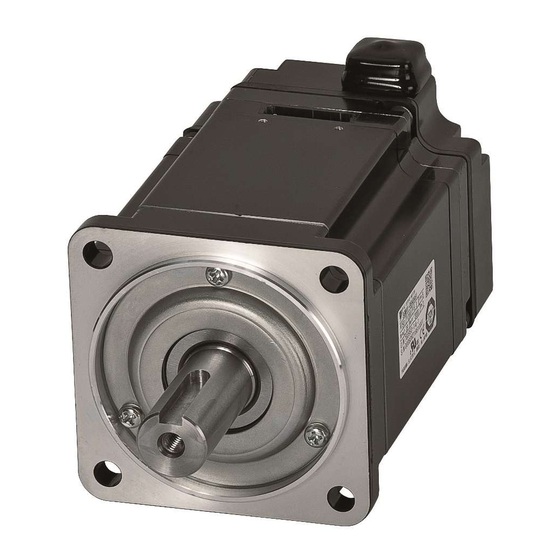
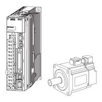
AC Servo Drives, Rotational Motor, Analog Voltage and Pulse Train Reference, SERVOPACK, Servomotors
Brand: YASKAWA
|
Category: Servo Drives
|
Size: 6 MB
Table of Contents
-
Warranty11
-
Part Names22
-
Ratings23
-
Overview45
-
Wire Types55
-
Single-Phase56
-
Three-Phase56
-
Noise Filter101
-
Operation108
-
Limitations117
-
Servo on Signal122
-
Signal Setting122
-
Overtravel124
-
Holding Brakes127
-
Speed Control140
-
Signal Setting140
-
Soft Start144
-
Position Control150
-
Electronic Gear157
-
Smoothing160
-
Torque Control164
-
Signal Setting164
-
Limiting Torque177
-
Input Signals178
-
Safety Function201
-
Risk Assessment201
-
Dynamic Brake205
-
Adjustments213
-
Torque Limit219
-
Notch Filter236
-
Operating Flow267
-
Notch Filter285
-
Operation289
-
Signal (Fn00E)304
-
Signal (Fn00F)307
-
Easyfft (Fn206)320
Advertisement
YASKAWA SGDV User Manual (400 pages)
AC ?-V Series
Brand: YASKAWA
|
Category: Servo Drives
|
Size: 15 MB
Table of Contents
-
-
Part Names19
-
-
Ratings20
-
-
-
-
-
-
-
-
-
Servo on Signal111
-
Overtravel113
-
Holding Brakes115
-
-
Limiting Torque167
-
-
Safety Function186
-
-
-
Easyfft (Fn206)299
-
-
-
-
-
Setting Order323
-
Electronic Gear330
-
Alarm Detection330
-
-
Troubleshooting333
-
YASKAWA SGDV User Manual (320 pages)
AC Servo Drives DC Power Input Design and Maintenance
Table of Contents
-
Warranty11
-
-
Part Names20
-
-
Ratings21
-
-
-
-
-
Limiting Torque133
-
-
-
-
Fn00F239
-
-
Easyfft (Fn206)248
Advertisement

YASKAWA SGDV User Manual (113 pages)
AC Servo Drives.
E-V series.
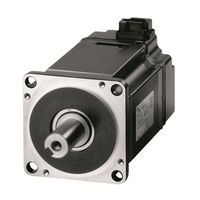
Rotational Motor
Brand: YASKAWA
|
Category: Servo Drives
|
Size: 8 MB
Table of Contents
-
Warranty15
-
-
YASKAWA SGDV User Manual (55 pages)
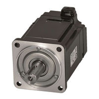
AC Servo Drives DC Power Input Rotational Motor
Brand: YASKAWA
|
Category: Servo Drives
|
Size: 1 MB
Table of Contents
-
Warranty12
-
-
Advertisement