Dell Force10 MXL Blade Configuration Manual
Configuration guide for the mxl 10/40gbe switch io module
Hide thumbs
Also See for Force10 MXL Blade:
- Reference manual (732 pages) ,
- Deployment manual (89 pages) ,
- Getting started manual (38 pages)

Related Manuals for Dell Force10 MXL Blade


Summary of Contents for Dell Force10 MXL Blade
- Page 1 Dell Force10 Configuration Guide for the MXL 10/40GbE Switch IO Module Publication Date: March 2013...
- Page 2 © 2013 Dell Force10. All rights reserved. Reproduction of these materials in any manner whatsoever without the written permission of Dell Inc. is strictly forbidden. Trademarks used in this text: Dell™, the DELL logo, Dell Precision™, OptiPlex™, Latitude™, PowerEdge™, PowerVault™, PowerConnect™, OpenManage™, EqualLogic™, KACE™, FlexAddress™...
-
Page 3: Table Of Contents
1 About this Guide ..........23 Objectives . - Page 4 4 Management ........... . . 51 Configure Privilege Levels .
- Page 5 Layer 4 ACL Rules Examples ........75 Configure a Standard IP ACL .
- Page 6 View CAM-ACL Settings ..........111 CAM Optimization .
- Page 7 9 Dynamic Host Configuration Protocol (DHCP) ......159 Overview ............159 DHCP Packet Format and Options .
- Page 8 DHCP MAC Source Address Validation.......185 IP+MAC Source Address Validation ....... . .185 10 FIP Snooping.
- Page 9 Enabling IGMP Immediate-leave ........216 Disabling Multicast Flooding .
- Page 10 Exclude a Smaller Port Range........240 Overlap Port Ranges .
- Page 11 Information Monitored in iSCSI Traffic Flows ......279 Detection and Autoconfiguration for Dell EqualLogic Arrays ....280 Detection and Port Configuration for Dell Compellent Arrays .
- Page 12 LACP Basic Configuration Example ........294 Configuring a LAG on ALPHA .
- Page 13 Configuring Transmit and Receive Mode ........328 Configuring a Time to Live .
- Page 14 Configuration Information ..........365 Configuration Task List for OSPFv2 (OSPF for IPv4) .
- Page 15 Modify Global PVST+ Parameters .........407 Enable BPDU Filtering globally .
- Page 16 Implementation Information ..........436 Configuration Information .
- Page 17 28 Security ............473 AAA Accounting .
- Page 18 Using SCP with SSH to Copy a Software Image ......495 Secure Shell Authentication ......... .496 Important Points to Remember for SSH Authentication.
- Page 19 Configure Contact and Location Information Using SNMP ..... .521 Subscribe to Managed Object Value Updates using SNMP .....522 Copy Configuration Files Using SNMP .
- Page 20 Merging Two Stacks ..........558 Splitting a Stack .
- Page 21 Root Guard Configuration ..........592 SNMP Traps for Root Elections and Topology Changes .
- Page 22 VLANs and Port Tagging ..........625 Configuration Task List for VLANs .
- Page 23 Displaying Drop Counters ..........662 Dataplane Statistics .
-
Page 25: About This Guide
This guide describes the supported protocols and software features, and provides configuration instructions and examples, for the Dell Force10 MXL 10/40GbE Switch IO Module running FTOS version 8.3.16.4. The MXL 10/40GbE Switch IO Module is installed in a Dell PowerEdge M1000e Enclosure. For information about how to install and perform the initial switch configuration, refer to the Getting Started Guides on the Dell Support website at http://support.dell.com/manuals. -
Page 26: Conventions
This symbol is a note associated with some other text on the page that is marked with an asterisk. Related Documents For more information about the Dell Force10 MXL 10/40GbE Switch IO Module, refer to the following documents: • FTOS Command Reference •... -
Page 27: Configuration Fundamentals
MXL Switch using the FTOS command-line interface. For information about how to access the CMC to configure an MXL Switch, refer to the Dell Chassis Management Controller (CMC) User's Guide on the Dell Support website at http://support.dell.com/support/edocs/systems/pem/en/... -
Page 28: Cli Modes
CLI Modes Different sets of commands are available in each mode. A command found in one mode cannot be executed from another mode (with the exception of EXEC mode commands preceded by the command for more information, refer to The do Command and EXEC Privilege Mode commands). -
Page 29: Navigating Cli Modes
Figure 2-2. CLI Modes in FTOS Navigating CLI Modes The FTOS prompt changes to indicate the CLI mode. Table 2-1 lists the CLI mode, its prompt, and information about how to access and exit this CLI mode. You must move linearly through the command modes, with the exception of the command, which takes you directly to EXEC Privilege mode and the command moves you up one command mode level. - Page 30 Table 2-1. FTOS Command Modes Access Command CLI Command Mode Prompt CONFIGURATION FTOS(conf)# • From EXEC privilege mode, enter the command configure • From every mode except EXEC and EXEC Privilege, enter the command exit Note: Access the following modes from CONFIGURATION mode: 10 Gigabit Ethernet FTOS(conf-if-te-0/1) Interface...
-
Page 31: The Do Command
Table 2-1. FTOS Command Modes Access Command CLI Command Mode Prompt PROTOCOL GVRP FTOS(conf-gvrp) protocol gvrp PROTOCOL LLDP FTOS(conf-lldp) protocol lldp Per-VLAN SPANNING FTOS(conf-pvst)# protocol spanning-tree pvst TREE Plus RAPID SPANNING FTOS(conf-rstp)# protocol spanning-tree rstp TREE route-map ROUTE-MAP FTOS(conf-route-map)# ROUTER OSPF FTOS(conf-router_ospf)# router ospf ROUTER RIP... -
Page 32: Undoing Commands
Figure 2-4. Using the Command FTOS(conf)#do show system brief “do” form of show command Stack MAC : 00:1e:c9:f1:04:22 Reload Type : normal-reload [Next boot : normal-reload] Stack Info Unit UnitType Status ReqTyp CurTyp Version Ports ------------------------------------------------------------------------------------ Management online MXL-10/40GbE MXL-10/40GbE 8-3-16-47 Member not present... -
Page 33: Obtaining Help
Layer 2 protocols are disabled by default. Enable them using the command. For example, in no disable PROTOCOL SPANNING TREE mode, enter to enable Spanning Tree. no disable Obtaining Help Obtain a list of keywords and a brief functional description of those keywords at any CLI mode using the commands: help •... -
Page 34: Entering And Editing Commands
Entering and Editing Commands When entering commands: • The CLI is not case sensitive. • You can enter partial CLI keywords. • You must enter the minimum number of letters to uniquely identify a command. For example, cannot be entered as a partial keyword because both the commands begin with clock class-map... -
Page 35: Command History
Command History FTOS maintains a history of previously-entered commands for each mode. For example: • When you are in EXEC mode, the UP and DOWN arrow keys display the previously-entered EXEC mode commands. • When you are in CONFIGURATION mode, the UP or DOWN arrows keys recall the previously-entered CONFIGURATION mode commands. - Page 36 • displays text that does not match the specified text. Figure 2-10 shows this command used in except combination with the command. do show stack-unit all stack-ports all pfc details | except 0 Figure 2-10. Filtering Command Outputs with the Command except FTOS(conf)#do show stack-unit all stack-ports all pfc details | except 0...
-
Page 37: Multiple Users In Configuration Mode
% Warning: User "<username>" on line vty0 "10.11.130.2" is in configuration mode If either of these messages appear, Dell Force10 recommends coordinating with the users listed in the message so that you do not unintentionally overwrite each other’s configuration changes. - Page 38 Configuration Fundamentals...
-
Page 39: Console Access
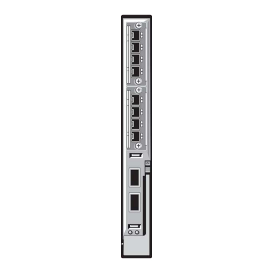
• View the Command History • Upgrading and Downgrading FTOS When the boot process is complete, the console monitor displays the Dell Force10 operating software (FTOS) banner and EXEC mode prompt (Figure 3-2). For details about using the command line interface (CLI), refer to the... - Page 40 Figure 3-1. Serial Console Flex IO Module in Expansion slot 1 Flex IO Module in Expansion slot 0 USB Storage port 40 GbE QSFP+ ports Console port Getting Started...
-
Page 41: External Serial Port With A Usb Connector
For the console port piMnout, refer to Table 3-1. To access the console port, follow these steps. Step Task Connect the USB connector to the front panel. Use the RS-232 Serial Line cable to connect the MXL 10/40GbE Switch IO Module console port to a terminal server. Connect the other end of the cable to the DTE terminal server. - Page 42 Boot Selector: Booting Bootflash Partition A image... Copying stage-2 loader from 0xb6120000 to 0x8c100000(size = 0x100000) Boot Image selection DONE. ## Starting application at 0x8C100000 ... U-Boot 2010.03-rc1(Dell Force10) Built by build at tools-sjc-01 on Thu May 31 23:53:38 2012 IOM Boot Label 4.0.1.0 Getting Started...
- Page 43 ---------------------------- --More-- Starting Dell Force10 application Welcome to Dell Easy Setup Wizard The setup wizard guides you through the initial switch configuration, and gets you up and running as quickly as possible. You can skip the setup wizard, and enter CLI mode to manually configure the switch. You must respond to the next question to run the setup wizard within 60 seconds, otherwise the system will continue with normal operation using the default system configuration.
-
Page 44: Default Configuration
Default Configuration A version of FTOS is pre-loaded onto the chassis; however, the system is not configured when you power up for the first time (except for the default hostname, which is FTOS). You must configure the system using the CLI. Configure a Host Name The host name appears in the prompt. -
Page 45: Configure The Management Port Ip Address
3. Configure a username and password. Refer to Configure a Username and Password. Configure the Management Port IP Address Assign IP addresses to the management ports in order to access the system remotely. To configure the management port IP address, follow these steps: Step Task Command Syntax... -
Page 46: Configure A Username And Password
• 7 is for inputting a password that is already encrypted using a DES hash. Obtain the encrypted password from the configuration file of another Dell Force10 system. Can be used only for enable password. • 5 is for inputting a password that is already encrypted using an MD5 hash. -
Page 47: Configuration File Management
You can store on and access files from various storage media. Rename, delete, and copy files on the system from EXEC Privilege mode. Note: Using flash memory cards in the system that have not been approved by Dell Force10 can cause unexpected system behavior, including a reboot. -
Page 48: Save The Running-Configuration
FTOS#copy flash://FTOS-EF-8.2.1.0.bin ftp://myusername:mypassword@10.10.10.10//FTOS/FTOS-EF-8.2.1.0 !!!!!!!!!!!!!!!!!!!!!!!!!!!!!!!!!!!!!!!!!!!!!!!!!!!!!!!!!!!!!!!!!!!!!!!!!!!!! 27952672 bytes successfully copied Figure 3-6 shows an example of using the command to import a file to the Dell Force10 system from copy an FTP server. Figure 3-6. Copying a file from a Remote System Remote Location Local Location core1#$//copy ftp://myusername:mypassword@10.10.10.10//FTOS/FTOS-EF-8.2.1.0.bin flash://... -
Page 49: View Files
Task Command Syntax Command Mode Save the running-configuration to: copy running-config startup-config the startup-configuration on the internal flash the usb flash on the IOM copy running-config usbflash://filename an FTP server copy running-config ftp:// username:password@{hostip hostname}/filepath/ EXEC Privilege filename a TFTP server copy running-config tftp://{hostip hostname}/filepath/ filename... -
Page 50: View Configuration Files
Figure 3-7. Viewing a List of Files in the Internal Flash FTOS#dir Directory of flash: drwx 4096 Jan 01 1980 00:00:00 +00:00 . drwx 2048 May 10 2011 14:45:15 +00:00 .. drwx 4096 Feb 17 2011 00:28:00 +00:00 TRACE_LOG_DIR drwx 4096 Feb 17 2011 00:28:02 +00:00 CORE_DUMP_DIR d---... -
Page 51: File System Management
--More-- File System Management The Dell Force10 system can use the internal Flash, USB Flash, or remote devices to store files. The system stores files on the internal Flash by default, but you can configure it to store files elsewhere. -
Page 52: View The Command History
You can change the default storage location to the USB Flash (Figure 3-10). File management commands then apply to the USB Flash rather than the internal Flash. Figure 3-10. Alternative Storage Location FTOS#cd usbflash: No File System Specified FTOS#copy running-config test 3998 bytes successfully copied FTOS#dir Directory of usbflash:... -
Page 53: Management
Management This chapter explains the different protocols or services used to manage the Dell Force10 system including: • Configure Privilege Levels • Configure Logging • File Transfer Services • Terminal Lines • Lock CONFIGURATION Mode • Recovering from a Forgotten Password •... -
Page 54: Removing A Command From Exec Mode
Removing a Command from EXEC Mode Remove a command from the list of available commands in EXEC mode for a specific privilege level using the command from CONFIGURATION mode. In the command, specify a level greater privilege exec than the level given to a user or terminal line, followed by the first keyword of each command to be restricted. - Page 55 Task Command Syntax Command Mode Allow access to INTERFACE, LINE, ROUTE-MAP, privilege configure level level CONFIGURATION and/or ROUTER mode. Specify all keywords in the {interface line route-map router} command. {command-keyword ||...|| command-keyword} Allow access to a CONFIGURATION, INTERFACE, privilege {configure interface line CONFIGURATION...
- Page 56 Figure 4-1. Create a Custom Privilege Level Apply a Privilege Level to a Username FTOS(conf)#do show run privilege FTOS(conf)#privilege exec level 3 capture FTOS(conf)#privilege exec level 3 configure FTOS(conf)#privilege exec level 4 resequence FTOS(conf)#privilege exec level 3 clear arp-cache FTOS(conf)#privilege exec level 3 clear arp-cache max-buffer-size FTOS(conf)#privilege configure level 3 line FTOS(conf)#privilege configure level 3 interface FTOS(conf)#do telnet 10.11.80.201...
-
Page 57: Apply A Privilege Level To A Terminal Line
To set a privilege level for a user: Task Command Syntax Command Mode Configure a privilege level for a user. CONFIGURATION username username privilege level Apply a Privilege Level to a Terminal Line To set a privilege level for a terminal line: Task Command Syntax Command Mode... -
Page 58: Disable System Logging
Disable System Logging By default, logging is enabled and log messages are sent to the logging buffer, all terminal lines, console, and syslog servers. To enable and disable system logging: Task Command Syntax Command Mode Disable all logging except on the console. no logging on CONFIGURATION Disable logging to the logging buffer. -
Page 59: Display The Logging Buffer And The Logging Configuration
To change the severity level of messages logged to a syslog server, use any or all of the following commands in CONFIGURATION mode: Task Command Syntax Command Mode Specify the minimum severity level for logging to the CONFIGURATION logging buffered level logging buffer. - Page 60 Figure 4-2. show logging Command Example FTOS#show logging Syslog logging: enabled Console logging: level debugging Monitor logging: level debugging Buffer logging: level debugging, 58 Messages Logged, Size (40960 bytes) Trap logging: level informational Logging to 172.31.1.4 Logging to 172.16.1.162 Logging to 133.33.33.4 Logging to 10.10.10.4 Logging to 10.1.2.4 May 20 20:00:10: %STKUNIT0-M:CP %SYS-5-CONFIG_I: Configured from vty0 ( 10.11.68...
-
Page 61: Configure A Unix Logging Facility Level
Configure a UNIX Logging Facility Level You can save system log messages with a UNIX system logging facility. To configure a UNIX logging facility level, use the following command in CONFIGURATION mode: Command Syntax Command Mode Purpose logging facility [facility-type] CONFIGURATION Specify one of the following parameters. -
Page 62: Synchronize Log Messages
Synchronize log messages You can configure FTOS to filter and consolidate system messages for a specific line by synchronizing the message output. Only the messages with a severity at or below the set level appear. This feature works on the terminal and console connections available on the system. To synchronize log messages, use these commands in the following sequence starting in CONFIGURATION mode: Step... -
Page 63: Enable Timestamp On Syslog Messages
Enable timestamp on Syslog Messages By default, syslog messages do not include a time/date stamp stating when the error or message was created. To have FTOS include a timestamp with the syslog message, use the following command syntax in CONFIGURATION mode: Command Syntax Command Mode Purpose... -
Page 64: Enable The Ftp Server
Enable the FTP Server To enable the system as an FTP server, use the following command in CONFIGURATION mode: Command Syntax Command Mode Purpose CONFIGURATION Enable FTP on the system. ftp-server enable To view the FTP configuration, enter the command in EXEC privilege mode show running-config ftp (Figure 4-4). -
Page 65: Configure Ftp Client Parameters
The virtual terminal lines (VTY) connect you through Telnet to the system. Deny and Permit Access to a Terminal Line Dell Force10 recommends applying only standard access control lists (ACLs) to deny and permit access to VTY lines. •... -
Page 66: Configure Login Authentication For Terminal Lines
Figure 4-5. Applying an Access List to a VTY Line FTOS(conf-std-nacl)#show config ip access-list standard myvtyacl seq 5 permit host 10.11.0.1 FTOS(conf-std-nacl)#line vty 0 FTOS(conf-line-vty)#show config line vty 0 access-class myvtyacl FTOS Behavior: Prior to FTOS version 7.4.2.0, in order to deny access on a VTY line, you must apply an ACL and AAA authentication to the line. -
Page 67: Time Out Of Exec Privilege Mode
Step Task Command Syntax Command Mode If you used the line authentication password LINE method in the method list you applied to the terminal line, configure a password for the terminal line. VTY lines 0-2 use a single authentication method, (Figure 4-6). -
Page 68: Telnet To Another Network Device
Figure 4-7. Configuring EXEC Timeout FTOS(conf)#line con 0 FTOS(conf-line-console)#exec-timeout 0 FTOS(conf-line-console)#show config line console 0 exec-timeout 0 0 FTOS(conf-line-console)# Telnet to Another Network Device To telnet to another device (Figure 4-8): Task Command Syntax Command Mode Telnet to the stack-unit.You do not need to configure the management telnet-peer-stack-unit EXEC Privilege port on the stack-unit to be able to telnet to it. -
Page 69: Viewing The Configuration Lock Status
You can set two types of locks: auto and manual. • Set an auto-lock using the command from CONFIGURATION mode. configuration mode exclusive auto When you set an auto-lock, every time a user is in CONFIGURATION mode, all other users are denied access. -
Page 70: Recovering From A Forgotten Password
You can then send any user a message using the command from EXEC Privilege mode. Alternatively send you can clear any line using the command from EXEC Privilege mode. If you clear a console session, clear the user is returned to EXEC mode. Recovering from a Forgotten Password If you configure authentication for the console and you exit out of EXEC mode or your console session times out, you are prompted to re-enter the password. -
Page 71: Recovering From A Failed Start
Step Task Command Syntax Command Mode Power-cycle the chassis by switching off all of the power modules and then switching them back on. Hit any key to abort the boot process. hit any key (during bootup) You enter uBoot immediately, as indicated by the =>... - Page 72 Management...
-
Page 73: Access Control Lists (Acls)
Access Control Lists (ACLs) This chapter describes the access control lists (ACLs), prefix lists, and route-maps. This chapter contains the following sections: • IP Access Control Lists (ACLs) • IP Fragment Handling • Configure a Standard IP ACL • Configure an Extended IP ACL •... -
Page 74: Ip Access Control Lists (Acls)
IP Access Control Lists (ACLs) In the Dell Force10 switch/routers, you can create two different types of IP ACLs: standard or extended. A standard ACL filters packets based on the source IP packet. An extended ACL filters packets based on the following criteria: •... -
Page 75: Acls And Vlans
• L3 Ingress Access list • L3 Egress Access list Note: IP ACLs are supported over VLANs in Version 6.2.1.1 and higher. ACLs and VLANs There are some differences when assigning ACLs to a VLAN rather than a physical port. For example, when using a single port-pipe, if you apply an ACL to a VLAN, one copy of the ACL entries gets installed in the ACL CAM on the port-pipe. -
Page 76: Ip Fragment Handling
Figure 5-1. Using the Order Keyword in ACLs FTOS(conf)#ip access-list standard acl1 FTOS(conf-std-nacl)#permit 20.0.0.0/8 FTOS(conf-std-nacl)#exit FTOS(conf)#ip access-list standard acl2 FTOS(conf-std-nacl)#permit 20.1.1.0/24 order 0 FTOS(conf-std-nacl)#exit FTOS(conf)#class-map match-all cmap1 FTOS(conf-class-map)#match ip access-group acl1 FTOS(conf-class-map)#exit FTOS(conf)#class-map match-all cmap2 FTOS(conf-class-map)#match ip access-group acl2 FTOS(conf-class-map)#exit FTOS(conf)#policy-map-input pmap FTOS(conf-policy-map-in)#service-queue 3 class-map cmap1 FTOS(conf-policy-map-in)#service-queue 1 class-map cmap2... -
Page 77: Layer 4 Acl Rules Examples
To deny second/subsequent fragments, use the same rules in a different order. These ACLs deny all second & subsequent fragments with destination IP 10.1.1.1 but permit the first fragment & non fragmented packets with destination IP 10.1.1.1 (Figure 5-3). Figure 5-3. Deny Second Packets FTOS(conf)#ip access-list extended ABC FTOS(conf-ext-nacl)#deny ip any 10.1.1.1/32 fragments FTOS(conf-ext-nacl)#permit ip any 10.1.1.1/32... -
Page 78: Configure A Standard Ip Acl
Note the following when configuring ACLs with the fragments keyword. When an ACL filters packets, it looks at the fragment offset (FO) to determine whether or not it is a fragment. FO = 0 means it is either the first fragment or the packet is a non-fragment. FO >... -
Page 79: Configuration Mode
Figure 5-6. Command Example: show ip accounting access-list FTOS#show ip accounting access ToOspf interface tengig 1/6 Standard IP access list ToOspf seq 5 deny any seq 10 deny 10.2.0.0 /16 seq 15 deny 10.3.0.0 /16 seq 20 deny 10.4.0.0 /16 seq 25 deny 10.5.0.0 /16 seq 30 deny 10.6.0.0 /16 seq 35 deny 10.7.0.0 /16... -
Page 80: Configure An Extended Ip Acl
Figure 5-8 shows a standard IP ACL in which the sequence numbers were assigned by FTOS. The filters were assigned sequence numbers based on the order in which they were configured (for example, the first filter was given the lowest sequence number). The command in IP ACCESS LIST mode show config displays the two filters with the sequence numbers 5 and 10. -
Page 81: Configure Filters With A Sequence Number
Configure Filters with a Sequence Number To create a filter for packets with a specified sequence number, follow these steps, starting in CONFIGURATION mode: Step Command Syntax Command Mode Purpose ip access-list extended CONFIGURATION Enter the IP ACCESS LIST mode by creating access-list-name an extended IP ACL. -
Page 82: Established Flag
To configure a filter for an extended IP ACL without a specified sequence number, use any or all of the following commands in IP ACCESS LIST mode: Command Syntax Command Mode Purpose {deny | permit} {source mask | any | host CONFIG-EXT-NACL Configure a deny or permit filter to ip-address} [count [byte]] [order] [fragments]... -
Page 83: Configuring Layer 2 And Layer 3 Acls On An Interface
Configuring Layer 2 and Layer 3 ACLs on an Interface You can configure both Layer 2 and Layer 3 ACLs on an interface in Layer 2 mode. If both L2 and L3 ACLs are applied to an interface, the following rules apply: •... -
Page 84: Counting Acl Hits
You can apply the same ACL to different interfaces and that changes its functionality. For example, you can take ACL “ABCD”, and apply it using the keyword and it becomes an ingress access list. If you apply the same ACL using the keyword, it becomes an egress access list. -
Page 85: Configuring Ingress Acls
To view the number of packets matching an ACL that is applied to an interface, follow these steps: Step Task Create an ACL that uses rules with the count option. Refer to Configure a Standard IP ACL Apply the ACL as an inbound or outbound ACL on an interface. Refer to Assign an IP ACL to an Interface View the number of packets matching the ACL using the show ip accounting access-list... -
Page 86: Configuring Egress Acls
Configuring Egress ACLs Configuring egress ACLs onto physical interfaces protects the system infrastructure from attack— malicious and incidental—by explicitly allowing only authorized traffic.These system-wide ACLs eliminate the need to apply ACLs onto each interface and achieves the same results. By localizing target traffic, it is a simpler implementation. -
Page 87: Ip Prefix Lists
The Control Plane Egress Layer 3 ACL feature enhances IP reachability debugging by implementing control-plane ACLs for CPU-generated and CPU-forwarded traffic. Using rules with the permit count option, you can track on a per-flow basis whether CPU-generated and CPU-forwarded packets were transmitted successfully.. -
Page 88: Implementation Information
The following rules apply to prefix lists: • A prefix list without any permit or deny filters allows all routes. • An “implicit deny” is assumed (that is, the route is dropped) for all route prefixes that do not match a permit or deny filter in a configured prefix list. - Page 89 If you want to forward all routes that do not match the prefix list criteria, you must configure a prefix list filter to permit all routes ( ). The “permit all” filter must be the last filter in your prefix permit 0.0.0.0/0 le 32 list.
-
Page 90: Command Syntax
Figure 5-16 shows a prefix list in which the sequence numbers were assigned by the software. The filters were assigned sequence numbers based on the order in which they were configured (for example, the first filter was given the lowest sequence number). The command in PREFIX LIST mode displays show config the two filters with the sequence numbers 5 and 10. -
Page 91: Use A Prefix List For Route Redistribution
Use a Prefix List for Route Redistribution To pass traffic through a configured prefix list, you must use the prefix list in a route redistribution command. The prefix list is applied to all traffic redistributed into the routing process and the traffic is either forwarded or dropped depending on the criteria and actions specified in the prefix list. -
Page 92: Acl Resequencing
To view the configuration, use the command in the ROUTER OSPF mode (Figure 5-20) or the show config command in EXEC mode. show running-config ospf Figure 5-20. Command Example: show config in ROUTER OSPF Mode FTOS(conf-router_ospf)#show config router ospf 34 network 10.2.1.1 255.255.255.255 area 0.0.0.1 distribute-list prefix awe in FTOS(conf-router_ospf)#... -
Page 93: Resequencing An Acl Or Prefix List
Resequencing an ACL or Prefix List Resequencing is available for IPv4 ACLs, prefix lists, and MAC ACLs. To resequence an ACL or prefix list, use the appropriate command in Table 5-4. When using these commands, you must specify the list name, starting number, and increment. -
Page 94: Route Maps
Figure 5-22. Resequencing Remarks FTOS(conf-ext-nacl)# show config ip access-list extended test remark 4 XYZ remark 5 this remark corresponds to permit any host 1.1.1.1 seq 5 permit ip any host 1.1.1.1 remark 9 ABC remark 10 this remark corresponds to permit ip any host 1.1.1.2 seq 10 permit ip any host 1.1.1.2 seq 15 permit ip any host 1.1.1.3 seq 20 permit ip any host 1.1.1.4... -
Page 95: Configuration Task List For Route Maps
• If no match is found in a route-map sequence, the process moves to the next route-map sequence until a match is found, or there are no more sequences. • When a match is found, the packet is forwarded; no more route-map sequences are processed. •... - Page 96 You can create multiple instances of this route map using the sequence number option to place the route maps in the correct order. FTOS processes the route maps with the lowest sequence number first. When a configured route map is applied to a command, such as , traffic passes through all instances of redistribute that route map until a match is found.
-
Page 97: Configure Route Map Filters
Configure Route Map Filters Within ROUTE-MAP mode, there are commands. commands search for a certain match match criterion in the routes and commands change the characteristics of those routes, either by adding something or by specifying a level. When there are multiple commands of the same parameter under one instance of a route-map, FTOS match does a match between either of those match commands. - Page 98 To configure match criterion for a route map, use any or all of the following commands in ROUTE-MAP mode: Command Syntax Command Mode Purpose match interface interface CONFIG-ROUTE-MAP Match routes whose next hop is a specific interface. The parameters are: •...
-
Page 99: Configure A Route Map For Route Redistribution
Use these commands to create route map instances. There is no limit to the number of match commands per route map, but the convention is to keep the number of match and set filters in a route map low. commands do not require a corresponding command. -
Page 100: Continue Clause
Figure 5-28, the command with a route map is used in ROUTER RIP mode to apply a tag redistribute ospf of 34 to all internal OSPF routes that are redistributed into RIP. Figure 5-28. Tagging OSPF Routes Entering a RIP Routing Domain router rip redistribute ospf 34 metric 1 route-map torip route-map torip permit 10... - Page 101 Access Control Lists (ACLs) | 99...
- Page 102 Access Control Lists (ACLs)
-
Page 103: Bare Metal Provisioning (Bmp)
Bare Metal Provisioning (BMP) Bare metal provisioning (BMP) improves accessibility to the MXL 10/40GbE Switch IO Module system. BMP performs auto configuration using a configuration file and an approved version of FTOS from a network source. BMP not only allows you to configure a stack with a minimum of effort, but it is also useful for quick configuration of a standalone system. - Page 104 Use reload mode to boot up, the system remains in the system memory. If the system undergoes an automatic reload, it reloads using the previously used mode. To use a different mode when the system reloads automatically, reboot the system in a new mode. The new mode is then retained in system memory. To view the current reload mode, use the command (Figure...
-
Page 105: Auto-Configuration
System Boot and Set-Up Behavior BMP Mode BMP mode is the boot mode configured for a new system arriving from Dell Force10. This mode obtains the FTOS image and configuration file from a network source (a DHCP server). Before implementing this mode, you must set up a DHCP server and an IP server. The necessary FTOS image and start-up configuration files must be located on the server for the system to retrieve. -
Page 106: Dhcp Configuration
TFTP option configfile "pt-MXLSWitchIO-12"; ##### bootfile-name could be given in the following way FTP URL with DNS option bootfile-name “ftp://admin:admin@Guest-1/jumpstart”; HTTP URL with IP address option bootfile-name "http://30.0.0.1/jumpstart”; TFTP URL with IP address option bootfile-name "tftp://30.0.0.1/jumpstart"; DHCP Configuration Prior to implementing BMP mode, you must update the dhcp.conf file on the appropriate DHCP server. •... -
Page 107: Ip Server
Boot file location IP address option routers code 3 = ip-address; subnet 30.0.0.0 netmask 255.255.0.0 { range 30.0.1.17 30.0.1.100; option tftp-server-address 30.0.0.1; (IP address) option tftp-server-address "Guest-1" (DNS) DNS server hostname option domain-name-servers 30.0.0.1; option routers 30.0.0.14; IP Server • Set up an IP server and ensure connectivity. -
Page 108: Boot Commands
Boot Commands Command Syntax Command Mode Purpose reload-type jump-start auto-save dhcp-timeout EXEC Privilege Reload the system in BMP mode. minutes config-download [enable |disable] To reload in non-BMP mode, enter reload-type retry-count normal command. Enter to download the config-download enable configuration file from the DHCP server. Enter config-download disable so that the system... - Page 109 2. The system sends DHCP Discover on all the interface up ports. 00:01:31: %STKUNIT0-M:CP %JUMPSTART-5-JUMPSTART_DISCOVER: DHCP DISCOVER sent on Ma 0/0. 00:01:31: %STKUNIT0-M:CP %JUMPSTART-5-JUMPSTART_DISCOVER: DHCP DISCOVER sent on Te 0/0. 00:01:31: %STKUNIT0-M:CP %JUMPSTART-5-JUMPSTART_DISCOVER: DHCP DISCOVER sent on Te 0/5. 00:01:31: %STKUNIT0-M:CP %JUMPSTART-5-JUMPSTART_DISCOVER: DHCP DISCOVER sent on Te 0/6. 00:01:47: %STKUNIT0-M:CP %JUMPSTART-5-JUMPSTART_DISCOVER: DHCP DISCOVER sent on Te 0/8.
- Page 110 • If there is a mismatch, the system upgrades to the downloaded version and reloads. *********VALID IMAGE*********** DOWNLOADED RELEASE HEADER : Release Image Major Version Release Image Minor Version Release Image Main Version Release Image Patch Version : 33 FLASH RELEASE HEADER B : Release Image Major Version Release Image Minor Version Release Image Main...
-
Page 111: Content Addressable Memory (Cam)
Content addressable memory (CAM) is a type of memory that stores information in the form of a look-up table (LUT). On Dell Force10 systems, the CAM stores Layer 2 and Layer 3 forwarding information, access-lists (ACL), flows, and routing policies. -
Page 112: Test Cam Usage
allocations must be entered as a factor of 2 (2, 4, 6, 8, 10). All other profile ipv6acl vman-dual-qos allocations can use either even or odd numbered ranges. Note: On the MXL 10/40GbE Switch IO Module, there can be only one odd number of blocks in the command line interface (CLI) configuration;... -
Page 113: View Cam-Acl Settings
Figure 7-1. Command Example: test cam-usage FTOS#test cam-usage service-policy input pmap stack-unit all Stack-Unit | Portpipe | CAM Partition | Available CAM | Estimated CAM per Port | Status ------------------------------------------------------------------------------------------ 0 | L2ACL 28 | 1 | Allowed (28) View CAM-ACL Settings View the current cam-acl settings for the system chassis and each component using the show cam-acl command... -
Page 114: Cam Optimization
CAM Optimization When you enable the CAM optimization command, if a policy map containing classification rules (ACL and/or dscp/ip-precedence rules) is applied to more than one physical interface on the same port-pipe, only a single copy of the policy is written (only one FP entry is used). When you disable this command, the system behaves as described in this chapter. -
Page 115: Data Center Bridging (Dcb)
DCB-enabled network is required in a data center. The Dell Force10 switches that support a unified fabric and consolidate multiple network infrastructures use a single input/output (I/O) device called a converged network adapter (CNA). -
Page 116: Priority-Based Flow Control
Data center bridging satisfies the needs of the following types of data center traffic in a unified fabric: • LAN traffic consists of a large number of flows that are generally insensitive to latency requirements, while certain applications, such as streaming video, are more sensitive to latency. Ethernet functions as a best-effort network that may drop packets in case of network congestion. -
Page 117: Enhanced Transmission Selection
Figure 8-1. Priority-Based Flow Control PFC is implemented as follows in the Dell Force10 operating software (FTOS): • PFC is supported on specified 802.1p priority traffic (dot1p 0 to 7) and is configured per interface. However, only two lossless queues are supported on an interface: one for FCoE converged traffic and one for SCSI storage traffic. - Page 118 Although you can configure strict-priority queue scheduling for a priority group, ETS introduces flexibility that allows the bandwidth allocated to each priority group to be dynamically managed according to the amount of LAN, storage, and server traffic in a flow. Unused bandwidth in a priority-group is dynamically allocated to other priority groups for which traffic is available to be scheduled.
-
Page 119: Data Center Bridging Exchange Protocol (Dcbx)
Data Center Bridging Exchange Protocol (DCBX) The data center bridging exchange (DCBX) protocol is enabled by default on any switch on which PFC or ETS are enabled. DCBX allows a switch to automatically discover DCB-enabled peers and exchange configuration information. PFC and ETS use DCBX to exchange and negotiate parameters with peer devices. -
Page 120: Enabling Data Center Bridging
Enabling Data Center Bridging Data center bridging is enabled by default on an MXL 10/40GbE Switch to support converged enhanced Ethernet (CEE) in a data center network, and is a prerequisite for configuring: • Priority-based flow control • Enhanced transmission selection •... -
Page 121: Qos Dot1P Traffic Classification And Queue Assignment
(refer to Policy-Based QoS Configurations). Note: Dell Force10 does not recommend mapping all ingress traffic to a single queue when using PFC service-class dynamic dot1p and ETS. Ingress traffic classification using the... -
Page 122: Configuring Priority-Based Flow Control
Configuring Priority-Based Flow Control Priority-based flow control provides a flow control mechanism based on the 802.1p priorities in converged Ethernet traffic received on an interface and is enabled by default. As an enhancement to the existing Ethernet pause mechanism, PFC stops traffic transmission for specified priorities (CoS values) without impacting other priority classes. - Page 123 FTOS Behavior: As soon as you apply a DCB policy with PFC enabled on an interface, DCBX starts exchanging information with PFC-enabled peers. The IEEE802.1Qbb, CEE and CIN versions of PFC TLV are supported. DCBX also validates PFC configurations received in TLVs from peer devices. If you reocnfigure the PFC priorities in an input policy and re-apply the policy to an interface, By applying a DCB input policy with PFC enabled, you enable PFC operation on ingress port traffic.
-
Page 124: Configuring Lossless Queues
Configuring Lossless Queues DCB also supports the manual configuration of lossless queues on an interface when PFC mode is turned off and priority classes are disabled in a DCB input policy applied to the interface. The configuration of no-drop queues provides flexibility for ports on which PFC is not needed but lossless traffic should egress from the interface. -
Page 125: Configuring The Pfc Buffer In A Switch Stack
Configuring the PFC Buffer in a Switch Stack In a switch stack, you must configure all stacked ports with the same PFC configuration. In addition, you must configure a separate buffer of memory allocated exclusively to a service pool accessed by queues on which priority-based control flows are mapped. -
Page 126: Configuring Enhanced Transmission Selection
Configuring Enhanced Transmission Selection Enhanced transmission selection (ETS) provides a way to optimize bandwidth allocation to outbound 802.1p classes of converged Ethernet traffic. Different traffic types have different service needs. Using ETS, you can create groups within an 802.1p priority class to configure different treatment for traffic with different bandwidth, latency, and best-effort needs. -
Page 127: Creating A Qos Ets Output Policy
Creating a QoS ETS Output Policy A QoS output policy that you create to optimize bandwidth on an output interface for specified priority traffic consists of the ETS settings used in DCBX negotiations with peer devices: • Bandwidth percentage • Queue scheduling To create a QoS output policy with ETS settings, follow these steps: Step... - Page 128 FTOS Behavior: Traffic in priority groups is assigned to strict-queue or WERR scheduling in an ETS output policy and is managed using the ETS bandwidth-assignment algorithm. FTOS deqeues all frames of strict-priority traffic before servicing any other queues. A queue with strict-priority traffic can starve other queues in the same port.
-
Page 129: Creating An Ets Priority Group
Creating an ETS Priority Group An ETS priority group specifies the range of 802.1p priority traffic to which a QoS output policy with ETS settings is applied on an egress interface. You can associate a priority group to more than one ETS output policy on different interfaces. -
Page 130: Applying An Ets Output Policy For A Priority Group To An Interface
Applying an ETS Output Policy for a Priority Group to an Interface To apply ETS on egress port traffic, you must associate a priority group with an ETS output policy which has scheduling and bandwidth configuration in a DCB output policy, and then apply the output policy to an interface. -
Page 131: Ets Operation With Dcbx
ETS Operation with DCBX In DCBX negotiation with peer ETS devices, ETS configuration is handled as follows: • ETS TLVs are supported in DCBX versions CIN, CEE, and IEEE2.5. • ETS operational parameters are determined by the DCBX port-role configurations (Configuring DCBX Operation). - Page 132 To create a QoS output policy that allocates different amounts of bandwidth to the different traffic types/ dot1p priorities assigned to a queue and apply the output policy to the interface, follow these steps. Step Task Command Command Mode qos-policy-output Create a QoS output policy.
-
Page 133: Applying Dcb Policies In A Switch Stack
Applying DCB Policies in a Switch Stack You can apply a DCB input policy with PFC configuration to all stacked ports in a switch stack or on a stacked switch. You can apply different DCB input policies to different stacked switches. Task Command Command Mode... -
Page 134: Configuring Dcbx Operation
Configuring DCBX Operation The data center bridging exchange protocol (DCBX) is used by DCB devices to exchange configuration information with directly connected peers using the link layer discovery protocol (LLDP) protocol. DCBX can detect the misconfiguration of a peer DCB device, and optionally, configure peer DCB devices with DCB feature settings to ensure consistent operation in a data center network. -
Page 135: Dcbx Port Roles
DCBX Port Roles Use the following DCBX port roles to enable the auto-configuration of DCBX-enabled ports and propagate DCB configurations learned from peer DCBX devices internally to other switch ports: • Auto-upstream: The port advertises its own configuration to DCBX peers and receives its configuration from DCBX peers (ToR or FCF device). -
Page 136: Dcb Configuration Exchange
On a DCBX port that is the configuration source, all PFC and application priority TLVs are enabled. ETS recommend TLVs are disabled and ETS configuration TLVs are enabled. • Manual - The port is configured to operate only with administrator-configured settings and does not auto-configure with DCB settings received from a DCBX peer or from an internally propagated configuration from the configuration source. -
Page 137: Configuration Source Election
Configuration Source Election When an auto-upstream or auto-downstream port receives a DCB configuration from a peer, the port first checks to see if there is an active configuration source on the switch. • If a configuration source already exists, the received peer configuration is checked against the local port configuration. -
Page 138: Auto-Detection And Manual Configuration Of The Dcbx Version
Auto-Detection and Manual Configuration of the DCBX Version When operating in Auto-Detection mode (dcbx version auto command in DCBX Configuration Procedure), a DCBX port automatically detects the DCBX version on a peer port. Legacy CIN and CEE versions are supported in addition to the standard IEEE version 2.5 DCBX. A DCBX port detects a peer version after receiving a valid frame for that version. -
Page 139: Dcbx Prerequisites And Restrictions
Figure 8-4. DCBX Sample Topology DCBX Prerequisites and Restrictions The following prerequisites and restrictions apply when you configure DCBX operation on a port: • DCBX requires LLDP in both send (TX) and receive (RX) mode to be enabled on a port interface (protocol lldp mode command;... -
Page 140: Dcbx Configuration Procedure
DCBX Configuration Procedure To configure an MXL Switch for DCBX operation in a data center network, you must: 1. Configure ToR- and FCF-facing interfaces as auto-upstream ports. 2. Configure server-facing interfaces as auto-downstream ports. 3. Configure a port to operate in a configuration-source role. 4. - Page 141 Step Task Command Command Mode Configure the DCBX port role used by the interface to [no] dcbx port-role PROTOCOL LLDP {config-source | exchange DCB information, where: auto-downstream | • configures the port to receive a peer auto-upstream auto-upstream | manual} configuration.
-
Page 142: Configuring Dcbx Globally On The Switch
Configuring DCBX Globally on the Switch To globally configure DCBX operation on a switch, follow these steps: Step Task Command Command Mode configure Enter Global Configuration mode. EXEC PRIVILEGE [no] protocol lldp Enter LLDP Configuration mode to enable DCBX CONFIGURATION operation. -
Page 143: Dcbx Error Messages
Step Task Command Command Mode Configure the Application Priority TLVs to be advertised [no] advertise dcbx-appln-tlv PROTOCOL LLDP {fcoe | iscsi} on unconfigured interfaces with a manual port-role, where: • fcoe enables the advertisement of FCoE in Application Priority TLVs. •... -
Page 144: Debugging Dcbx On An Interface
Debugging DCBX on an Interface To enabled DCBX debug traces for all or a specific control path, use the following command: Task Command Command Mode debug dcbx {all | auto-detect-timer | Enable DCBX debugging, where: EXEC PRIVILEGE config-exchng | fail | mgmt | •... -
Page 145: Verifying Dcb Configuration
Verifying DCB Configuration Use the show commands in Table 8-2 to display DCB configurations. Table 8-2. Displaying DCB Configurations Command Output show dot1p-queue mapping (Figure 8-5) Displays the current 802.1p priority-queue mapping. show dcb [stack-unit unit-number] (Figure 8-6) Displays data center bridging status, number of PFC-enabled ports, and number of PFC-enabled queues. - Page 146 Figure 8-8. show qos dcb-output Command Example FTOS# show qos dcb-output dcb-output ets priority-group san qos-policy san priority-group ipc qos-policy ipc priority-group lan qos-policy lan Figure 8-9. show qos priority-groups Command Example FTOS#show qos priority-groups priority-group ipc priority-list 4 set-pgid 2 Figure 8-10.
- Page 147 Table 8-3. show interface pfc summary Command Description Field Description Interface Interface type with stack-unit and port number. Admin mode is on PFC Admin mode is on or off with a list of the configured PFC priorities. Admin is enabled When PFC admin mode is on, PFC advertisements are enabled to be sent and received from peers;...
- Page 148 Table 8-3. show interface pfc summary Command Description Field Description PFC TLV Statistics: Number of PFC TLVs transmitted. Output TLV pkts PFC TLV Statistics: Number of PFC error packets received. Error pkts PFC TLV Statistics: Number of PFC pause frames transmitted. Pause Tx pkts PFC TLV Statistics: Number of PFC pause frames received...
- Page 149 Figure 8-12. show interface ets summary Command Example FTOS(conf)# show interfaces te 0/0 ets summary Interface TenGigabitEthernet 0/0 Max Supported TC Groups is 4 Number of Traffic Classes is 8 Admin mode is on Admin Parameters: ------------------ Admin is enabled TC-grp Priority# Bandwidth...
- Page 150 Figure 8-13. show interface ets detail Command Example FTOS(conf)# show interfaces tengigabitethernet 0/0 ets detail Interface TenGigabitEthernet 0/0 Max Supported TC Groups is 4 Number of Traffic Classes is 8 Admin mode is on Admin Parameters : ------------------ Admin is enabled TC-grp Priority# Bandwidth...
- Page 151 Table 8-4. show interface ets detail Command Description Field Description Interface Interface type with stack-unit and port number. Max Supported TC Group Maximum number of priority groups supported. Number of Traffic Classes Number of 802.1p priorities currently configured. Admin mode ETS mode: on or off.
- Page 152 Figure 8-14. show stack-unit all stack-ports all pfc details Command Example FTOS(conf)# show stack-unit all stack-ports all pfc details stack unit 0 stack-port all Admin mode is On Admin is enabled, Priority list is 4-5 Local is enabled, Priority list is 4-5 Link Delay 45556 pause quantum 0 Pause Tx pkts, 0 Pause Rx pkts stack unit 1 stack-port all...
- Page 153 Figure 8-16. show interface dcbx detail Command Example FTOS(conf)# show interface tengigabitethernet 0/49 dcbx detail FTOS#show interface te 0/49 dcbx detail E-ETS Configuration TLV enabled e-ETS Configuration TLV disabled R-ETS Recommendation TLV enabled r-ETS Recommendation TLV disabled P-PFC Configuration TLV enabled p-PFC Configuration TLV disabled F-Application priority for FCOE enabled f-Application Priority for FCOE disabled...
- Page 154 Table 8-5. show interface dcbx detail Command Description Field Description Local DCBX Compatibility DCBX version accepted in a DCB configuration as compatible. In mode auto-upstream mode, a port can only received a DCBX version supported on the remote peer. Local DCBX Configured mode DCBX version configured on the port: CEE, CIN, IEEE v2.5, or Auto (port auto-configures to use the DCBX version received from a peer).
-
Page 155: Pfc And Ets Configuration Examples
PFC and ETS Configuration Examples This section contains examples of how to configure and apply DCB input and output policies on an interface. Using PFC and ETS to Manage Data Center Traffic In the example shown in Figure 8-17 for an MXL 10/40GbE Switch: •... - Page 156 QoS Traffic Classification: On the MXL Switch, the command has been used service-class dynamic dot1p in Global Configuration mode to map ingress dot1p frames to the queues shown in Table 8-6. For more information, refer to QoS dot1p Traffic Classification and Queue Assignment.
- Page 157 Table 8-8. Example: priority group-bandwidth Assignment Priority Group Bandwidth Assignment Figure 8-18. PFC and ETS Configuration Command Example Configure QoS priority-queue assignment to honor dot1p priorities or use L2 class maps to mark and map ingress traffic to output queues; for example: FTOS(conf)# service-class dynamic dot1p FTOS(conf)# interface tengigabitethernet 0/1 FTOS(conf-if-te-0/1)#...
-
Page 158: Using Pfc And Ets To Manage Converged Ethernet Traffic In A Switch Stack
Figure 8-19. Example: DCB PFC and ETS Configuration (Continued) Configure a DCB output policy for applying ETS (bandwidth allocation and scheduling) to IPC, SAN, and LAN priority traffic: FTOS(conf)# dcb-output ets FTOS(conf-dcb-out)# priority-group san qos-policy san FTOS(conf-dcb-out)# priority-group lan qos-policy lan FTOS(conf-dcb-out)# priority-group ipc qos-policy ipc Apply DCB input and output policies to a port interface: FTOS(conf)# interface tengigabitethernet 0/1... -
Page 159: Hierarchical Scheduling In Ets Output Policies
Hierarchical Scheduling in ETS Output Policies On an MXL Switch, ETS supports up to three levels of hierarchical scheduling. For example, you can apply ETS output policies with the following configurations: • Priority group 1 assigns traffic to one priority queue with 20% of the link bandwidth and strict-priority scheduling. - Page 160 Data Center Bridging (DCB)
-
Page 161: Dynamic Host Configuration Protocol (Dhcp)
Skippy812 Dynamic Host Configuration Protocol (DHCP) This chapter contains the following sections: • Overview • Implementation Information • Configuration Tasks • Configure the System to be a DHCP Server • Configure the System to be a Relay Agent • Configure the System to be a DHCP Client •... -
Page 162: Dhcp Packet Format And Options
DHCP Packet Format and Options DHCP uses the user datagram protocol (UDP) as its transport protocol. The server listens on port 67 and transmits to port 68; the client listens on port 68 and transmits to port 67. The configuration parameters are carried as options in the DHCP packet in type, length, value (TLV) format;... -
Page 163: Assigning An Ip Address Using Dhcp
Assigning an IP Address Using DHCP When a client joins a network: 1. The client initially broadcasts a DHCPDISCOVER message on the subnet to discover available DHCP servers. This message includes the parameters that the client requires and might include suggested values for those parameters. -
Page 164: Configuration Tasks
Implementation Information • The Dell Force10 implementation of DHCP is based on RFC 2131 and RFC 3046. • IP source address validation is a sub-feature of DHCP snooping; FTOS uses ACLs internally to implement this feature and as such, you cannot apply ACLs to an interface which has IP source address validation. -
Page 165: Related Configuration Tasks
IP address ranges, lease length specifications, and configuration data that DHCP hosts need. Configuring the Dell Force10 system to be a DHCP server is a three-step process: Configure the Server for Automatic Address Allocation Specify a Default Gateway... -
Page 166: Exclude Addresses From The Address Pool
Step Task Command Syntax Command Mode network network /prefix-length Specify the range of IP addresses from which the DHCP <POOL> DHCP server may assign addresses. Prefix-length Range: 17 to 31 • network is the subnet address. • specifies the number of bits prefix-length used for the network portion of the address you specify. -
Page 167: Enable Dhcp Server
DNS Server Relay Agent Configure a Method of Hostname Resolution Dell Force10 systems are capable of providing DHCP clients with parameters for two methods of hostname resolution. Address Resolution using DNS A domain is a group of networks. DHCP clients query domain name server (DNS) IP servers when they need to correlate host names to IP addresses. -
Page 168: Address Resolution Using Netbios Wins
Specify the NetBIOS node type for a Microsoft DHCP <POOL> DHCP client. Dell Force10 recommends specifying clients as hybrid. Create Manual Binding Entries An address binding is a mapping between the IP address and media access control (MAC) address of a client. -
Page 169: Debug Dhcp Server
Routers do not forward broadcasts, so if there are no DHCP servers on the subnet, the client does not receive a response to its request and therefore cannot access the network. You can configure an interface on the Dell Force10 system to relay the DHCP messages to a specific DHCP server using the... - Page 170 Figure 9-4. Configuring Dell Force10 MXL 10/40GbE Switch IO Module system as a DHCP Relay Device To view the configuration for an interface, use the command from EXEC ip helper-address show ip interface privilege mode (Figure 9-5). Figure 9-5. Displaying the Helper Address Configuration...
-
Page 171: Configure The System To Be A Dhcp Client
Configure the System to be a DHCP Client A DHCP client is a network device that requests an IP address and configuration parameters from a DHCP server. On an MXL Switch, the DHCP client functionality is implemented as follows: • The switch can obtain a dynamically-assigned IP address from a DHCP server. - Page 172 To display DHCP client information, enter the following show commands: Task Command Syntax Command Mode Display statistics about DHCP client interfaces show ip dhcp client statistics EXEC Privilege interface type slot/port (Figure 9-6). Clear DHCP client statistics on a specified or on all clear ip dhcp client statistics {all | EXEC Privilege interface type slot/port}...
- Page 173 To enable debug messages for DHCP client operation, enter the following debug commands: Task Command Syntax Command Mode [no] debug ip dhcp client packets Enable the display of log messages for all DHCP packets EXEC Privilege [interface type slot/port] sent and received on DHCP client interfaces. Enable the display of log messages for the following [no] debug ip dhcp client events EXEC Privilege...
- Page 174 Figure 9-8. DHCP Client: Debug Messages Logged during DHCP Client Enabling/Disabling FTOS (conf-if-te-0/1)# ip address dhcp May 27 15:52:46: %STKUNIT0-M:CP %DHCLIENT-5-DHCLIENT-LOG: DHCLIENT_DBG_EVT: Interface Te 0/1 : DHCP ENABLE CMD Received in state START May 27 15:52:48: %STKUNIT0-M:CP %DHCLIENT-5-DHCLIENT-LOG: DHCLIENT_DBG_EVT: Interface Te 0/1: Transitioned to state SELECTING May 27 15:52:48: %STKUNIT0-M:CP %DHCLIENT-5-DHCLIENT-LOG: DHCLIENT_DBG_PKT: DHCP DISCOVER sent in Interface Te 0/1...
- Page 175 Figure 9-9 shows an example of the packet- and event-level debug messages displayed for the packet transmissions and state transitions on a DHCP client interface when you release and renew a DHCP client. Figure 9-9. DHCP Client: Debug Messages Logged during DHCP Client Release/Renew FTOS# release dhcp interface tengigabitethernet 0/1 May 27 15:55:22: %STKUNIT0-M:CP %DHCLIENT-5-DHCLIENT-LOG: DHCLIENT_DBG_EVT: Interface Te 0/1 : DHCP RELEASE CMD Received in state BOUND...
- Page 176 FTOS Behavior: The ip address dhcp command enables DHCP server-assigned dynamic IP addresses on an interface. This setting persists after a switch reboot. If you enter the shutdown command on the interface, DHCP transactions are stopped and the dynamically-acquired IP address is saved. Use the show interface type slot/port command to display the dynamic IP address and DHCP as the mode of IP address assignment.
-
Page 177: Dhcp Client On A Management Interface
DHCP Client on a Management Interface When you enable a management interface to operate as a DHCP client, the following conditions apply: • The management default route is added with the gateway as the router IP address received in the DHCP ACK packet. -
Page 178: Dhcp Client Operation With Other Features
DHCP Client Operation with other Features Stacking The DHCP client daemon runs only on the master unit and handles all DHCP packet transactions. The DHCP client running on the master unit periodically synchronizes the lease file with the standby unit. When a stack failover occurs, the new master requests the same DHCP server-assigned IP address on DHCP client interfaces. -
Page 179: Vrrp
VRRP You cannot enable DHCP client on an interface and set the priority to 255 or assign the same IP address acquired by DHCP to a VRRP virtual group. Setting the priority to 255 or assigning an interface IP address to a VRRP virtual group guarantees that this router becomes the VRRP group owner. -
Page 180: Configure Secure Dhcp
Configure Secure DHCP DHCP as defined by RFC 2131 provides no authentication or security mechanisms. Secure DHCP is a suite of features that protects networks that use dynamic address allocation from spoofing and attacks. • Option 82 • DHCP Snooping •... -
Page 181: Dhcp Snooping
DHCP Snooping DHCP snooping protects networks from spoofing. In the context of DHCP snooping, all ports are either trusted or untrusted. By default, all ports are untrusted. Trusted ports are ports through which attackers cannot connect. Manually configure ports connected to legitimate servers and relay agents as trusted. When you enable DHCP snooping, the relay agent builds a binding table—using DHCPACK messages—... -
Page 182: Add A Static Entry In The Binding Table
Add a Static Entry in the Binding Table To add a static entry in the binding table, follow this step: Task Command Syntax Command Mode ip dhcp snooping binding mac Add a static entry in the binding table. EXEC Privilege Clear the Binding Table To clear the binding table, follow this step: Task... -
Page 183: Drop Dhcp Packets On Snooped Vlans Only
To view the DHCP snooping statistics, use the command (Figure 9-10). show ip dhcp snooping Figure 9-10. Command example: show ip dhcp snooping FTOS#show ip dhcp snooping IP DHCP Snooping : Disabled. IP DHCP Snooping Mac Verification : Disabled. IP DHCP Relay Information-option : Disabled. -
Page 184: Dynamic Arp Inspection
To view the number of entries in the table, use the command. This output show ip dhcp snooping binding displays the snooping binding table created using the ACK packets from the trusted port (Figure 9-11). Figure 9-11. Command example: show ip dhcp snooping binding FTOS#show ip dhcp snooping binding Codes : S - Static D - Dynamic... - Page 185 • denial of service—an attacker can send fraudulent ARP messages to a client to associate a false MAC address with the gateway address, which blackholes all internet-bound packets from the client. Note: Dynamic ARP inspection (DAI) uses entries in the L2SysFlow CAM region, a sub-region of SystemFlow.
-
Page 186: Bypass The Arp Inspection
To see how many valid and invalid ARP packets have been processed, use the show arp inspection statistics command (Figure 9-13). Figure 9-13. Command example: show arp inspection database FTOS#show arp inspection statistics Dynamic ARP Inspection (DAI) Statistics --------------------------------------- Valid ARP Requests Valid ARP Replies : 1000 Invalid ARP Requests... -
Page 187: Ip Source Address Validation
IP Source Address Validation IP source address validation prevents IP spoofing by forwarding only IP packets that have been validated against the DHCP binding table. A spoofed IP packet is one in which the IP source address is strategically chosen to disguise the attacker. For example, using ARP spoofing, an attacker can assume a legitimate client’s identity and receive traffic addressed to it. - Page 188 To enable IP+MAC source address validation, follow these steps: Step Task Command Syntax Command Mode Allocate at least one FP block to the cam-acl l2acl CONFIGURATION ipmacacl CAM region. Save the running-config to the copy running-config startup-config EXEC Privilege startup-config. reload Reload the system.
-
Page 189: Fip Snooping
FIP Snooping FIP snooping is supported on the MXL 10/40GbE Switch This chapter describes the FIP snooping concepts and configuration procedures: • Fibre Channel over Ethernet • Ensuring Robustness in a Converged Ethernet Network • FIP Snooping on Ethernet Bridges •... - Page 190 To ensure similar Fibre Channel robustness and security with FCoE in an Ethernet cloud network, the Fibre Channel over Ethernet initialization protocol (FIP) establishes virtual point-to-point links between FCoE end-devices (server ENodes and target storage devices) and FCoE forwarders (FCFs) over transit FCoE-enabled bridges.
-
Page 191: Fip Snooping On Ethernet Bridges
Figure 10-1. FIP discovery and login between an ENode and an FCF FIP Snooping on Ethernet Bridges In a converged Ethernet network, intermediate Ethernet bridges can snoop on FIP packets during the login process on an FCF. Then, using ACLs, a transit bridge can permit only authorized FCoE traffic to be transmitted between an FCoE end-device and an FCF. - Page 192 • Port-based ACLs are applied on ports directly connected to an FCF and on server-facing ENode ports. • Port-based ACLs take precedence over global ACLs. • FCoE-generated ACLs take precedence over user-configured ACLs. A user-configured ACL entry cannot deny FCoE and FIP snooping frames. Figure 10-2 shows an MXL 10/40GbE Switch used as a FIP snooping bridge in a converged Ethernet network.
-
Page 193: Fip Snooping In A Switch Stack
In case of a failover, the new master switch starts the required timers for the FCoE database tables. Timers run only on the master stack unit. Note: As a best practice, Dell Force10 recommends that you do not configure FIP Snooping on a stacked MXL Switch. -
Page 194: Enabling The Fip Snooping Feature
Enabling the FIP Snooping Feature As soon as you enable the FIP snooping feature on a switch-bridge, existing VLAN-specific and FIP snooping configurations are applied. By default, all FCoE and FIP frames are dropped unless specifically permitted by existing FIP snooping-generated ACLs. You can reconfigure any of the FIP snooping settings. -
Page 195: Configuring A Port For A Bridge-To-Fcf Link
A FIP snooping bridge requires DCBX and PFC to be enabled on the switch for lossless Ethernet connections (refer to Data Center Bridging (DCB)). Dell recommends that you also enable ETS; ETS is recommended but not required. If you enable DCBX and PFC mode is on (PFC is operationally up) in a port configuration, FIP snoop- ing is operational on the port. -
Page 196: Fip Snooping Restrictions
FIP Snooping Restrictions The following restrictions apply when you configure FIP snooping on an MXL switch: • The maximum number of FCoE VLANs supported on the switch is eight. • The maximum number of FIP snooping sessions (including NPIV sessions) supported per ENode server is 16. -
Page 197: Displaying Fip Snooping Information
Displaying FIP Snooping Information Use the commands in Table 10-1 to display information on FIP snooping. show Table 10-1. Displaying FIP Snooping Information Command Output show fip-snooping sessions [interface vlan Displays information on FIP-snooped sessions on all VLANs or a specified vlan-id] (Figure 10-3) - Page 198 Figure 10-3. show fip-snooping sessions Command Example FTOS#show fip-snooping sessions Enode MAC Enode Intf FCF MAC FCF Intf VLAN aa:bb:cc:00:00:00 Te 0/42 aa:bb:cd:00:00:00 Te 0/43 aa:bb:cc:00:00:00 Te 0/42 aa:bb:cd:00:00:00 Te 0/43 aa:bb:cc:00:00:00 Te 0/42 aa:bb:cd:00:00:00 Te 0/43 aa:bb:cc:00:00:00 Te 0/42 aa:bb:cd:00:00:00 Te 0/43 aa:bb:cc:00:00:00...
- Page 199 Figure 10-5. show fip-snooping enode Command Example FTOS# show fip-snooping enode Enode MAC Enode Interface FCF MAC VLAN FC-ID --------- --------------- ------- ---- ----- d4:ae:52:1b:e3:cd Te 0/11 54:7f:ee:37:34:40 62:00:11 Table 10-3. show fip-snooping enode Command Description Field Description ENode MAC MAC address of the ENode.
- Page 200 Figure 10-7. show fip-snooping statistics (VLAN and port) Command Example FTOS# show fip-snooping statistics interface vlan 100 Number of Vlan Requests Number of Vlan Notifications Number of Multicast Discovery Solicits Number of Unicast Discovery Solicits Number of FLOGI Number of FDISC Number of FLOGO Number of Enode Keep Alive :9021...
- Page 201 Figure 10-8. show fip-snooping statistics (port channel) Command Example FTOS# show fip-snooping statistics interface port-channel 22 Number of Vlan Requests Number of Vlan Notifications Number of Multicast Discovery Solicits Number of Unicast Discovery Solicits Number of FLOGI Number of FDISC Number of FLOGO Number of Enode Keep Alive Number of VN Port Keep Alive...
- Page 202 Table 10-5. show fip-snooping statistics Command Descriptions Field Description Number of Vlan Requests Number of FIP-snooped VLAN request frames received on the interface. Number of VLAN Notifications Number of FIP-snooped VLAN notification frames received on the interface. Number of Multicast Discovery Number of FIP-snooped multicast discovery solicit frames received on the Solicits interface.
- Page 203 Figure 10-9. show fip-snooping system Command Example FTOS# show fip-snooping system Global Mode : Enabled FCOE VLAN List (Operational) : 1, 100 FCFs Enodes Sessions : 17 Note: NPIV sessions are included in the number of FIP-snooped sessions displayed. Figure 10-10. show fip-snooping vlan Command Example FTOS# show fip-snooping vlan * = Default VLAN VLAN...
-
Page 204: Fip Snooping Configuration Example
FIP Snooping Configuration Example Figure 10-11 shows an MXL Switch used as a FIP snooping bridge for FCoE traffic between an ENode (server blade) and an FCF (ToR switch). The ToR switch operates as an FCF and FCoE gateway. Figure 10-11. Configuration Example: FIP Snooping on an MXL 10/40GbE Switch Figure 10-11, DCBX and PFC are enabled on the MXL Switch (FIP snooping bridge) and on the FCF ToR switch. - Page 205 Figure 10-12 shows how to configure FIP snooping on FCoE VLAN 10, an FCF-facing port (0/50), and an ENode server-facing port (0/1), and to configure the FIP snooping ports as tagged members of the FCoE VLAN enabled for FIP snooping. Figure 10-12.
- Page 206 FIP Snooping...
-
Page 207: Garp Vlan Registration Protocol (Gvrp)
GARP VLAN Registration Protocol (GVRP) This chapter contains the following sections: • Configuring GVRP • Enabling GVRP Globally • Enabling GVRP on a Layer 2 Interface • Configuring GVRP Registration • Configuring a GARP Timer Overview Typical virtual local area network (VLAN) implementation involves manually configuring each Layer 2 switch that participates in a given VLAN. -
Page 208: Configuring Gvrp
• Dynamic VLANs are aged out after the LeaveAll timer expires three times without receipt of a Join message. Use the command to display status. show gvrp statistics {interface interface summary} • On the MXL Switch, per-VLAN spanning tree+ (PVST+) and GVRP cannot be enabled at the same time (Figure 11-1). -
Page 209: Related Configuration Tasks
Figure 11-2. GVRP Configuration Overview GVRP is configured globally and on all VLAN trunk ports for the edge and core switches. Edge Switches Edge Switches Core Switches VLANs 10-20 VLANs 70-80 VLANs 30-50 VLANs 10-20 VLANs 70-80 VLANs 30-50 NOTES: VLAN 1 mode is always fixed and cannot be configured All VLAN trunk ports must be configured for GVRP All VLAN trunk ports must be configured as 802.1Q... -
Page 210: Enabling Gvrp Globally
Enabling GVRP Globally Enable GVRP for the entire switch using the command in CONFIGURATION mode gvrp enable (Figure 11-3). Use the command to inspect the global configuration. show gvrp brief Figure 11-3. Enabling GVRP Globally FTOS(conf)#protocol gvrp FTOS(conf-gvrp)#no disable FTOS(conf-gvrp)#show config protocol gvrp no disable FTOS(conf-gvrp)#... -
Page 211: Configuring A Garp Timer
• Normal Registration: Allows dynamic creation, registration, and de-registration of VLANs (if you enabled dynamic VLAN creation). By default, the registration mode is set to normal when you enable GVRP on a port. This default mode enables the port to dynamically register and de-register VLANs, and to propagate both dynamic and static VLAN information. - Page 212 Figure 11-6 shows GVRP registration. Figure 11-6. Configuring GVRP Registration FTOS(conf)#garp timer leav 1000 FTOS(conf)#garp timers leave-all 5000 FTOS(conf)#garp timer join 300 Verification: FTOS(conf)#do show garp timer GARP Timers Value (milliseconds) ---------------------------------------- Join Timer Leave Timer 1000 LeaveAll Timer 5000 FTOS(conf)# FTOS displays Message 1...
-
Page 213: Internet Group Management Protocol (Igmp)
Internet Group Management Protocol (IGMP) Multicast is based on identifying many hosts by a single destination IP address. Hosts represented by the same IP address are a multicast group. The internet group management protocol (IGMP) is a Layer 3 multicast protocol that hosts use to join or leave a multicast group. Multicast routing protocols (such as protocol-independent multicast [PIM]) use the information in IGMP messages to discover which groups are active and to populate the multicast routing table. -
Page 214: Joining A Multicast Group
Figure 12-1. IGMP Version 2 Packet Format Padding Preamble Start Frame Destination MAC Source MAC Ethernet Type IP Packet Delimiter Version Total Length Flags Frag Offset Protocol Header Src IP Addr Dest IP Addr Options Padding IGMP Packet (0xc0) Checksum (Router Alert) Max. -
Page 215: Igmp Version 3
IGMP Version 3 Conceptually, IGMP version 3 behaves the same as version 2. However, there are differences: • Version 3 adds the ability to filter by multicast source, which helps the multicast routing protocols avoid forwarding traffic to subnets where there are no interested receivers. •... -
Page 216: Joining And Filtering Groups And Sources
Joining and Filtering Groups and Sources Figure 12-4 shows how multicast routers maintain the group and source information from unsolicited reports. 1. The first unsolicited report from the host indicates that it wants to receive traffic for group 224.1.1.1. 2. The host’s second report indicates that it is only interested in traffic from group 224.1.1.1, source 10.11.1.1. -
Page 217: Leaving And Staying In Groups
Leaving and Staying in Groups Figure 12-5 shows how multicast routers track and refresh state changes in response to group-and-specific and general queries. 1. Host 1 sends a message indicating it is leaving group 224.1.1.1 and that the included filter for 10.11.1.1 and 10.11.1.2 are no longer necessary. -
Page 218: Igmp Snooping Implementation Information
IGMP Snooping Implementation Information • IGMP snooping on the Dell Force 10 operating system (FTOS) uses IP multicast addresses not MAC addresses. • IGMP snooping is not supported on stacked VLANs. • IGMP snooping is supported on all MXL 10/40GbE stack members. -
Page 219: Disabling Multicast Flooding
Disabling Multicast Flooding If the switch receives a multicast packet that has an IP address of a group it has not learned (unregistered frame), the switch floods that packet out of all ports on the VLAN. On the MXL Switch, when you configure , the system forwards the frames on no ip igmp snooping flood mrouter ports for first 96 IGMP snooping enabled VLANs. -
Page 220: Fast Convergence After Mstp Topology Changes
Fast Convergence after MSTP Topology Changes When a port transitions to the forwarding state as a result of an STP or MSTP topology change, FTOS sends a general query out of all ports except the multicast router ports. The host sends a response to the general query and the forwarding database is updated without having to wait for the query interval to expire. -
Page 221: Interfaces
Interfaces This chapter describes 100/1000/10000 Mbps Ethernet, 10 Gigabit Ethernet, and 40 Gigabit Ethernet interface types, both physical and logical, and how to configure them with the Dell Force10 operating software (FTOS). Basic Interface Configuration: • Interface Types • View Basic Interface Information •... -
Page 222: Interface Types
Interface Types The following lists the different interface types. Modes Requires Interface Type Possible Default Mode Creation Default State Physical L2, L3 Unset Shutdown (disabled) Management No Shutdown (enabled) Loopback No Shutdown (enabled) Null Enabled Port Channel L2, L3 Shutdown (disabled) VLAN L2, L3 Yes (except... - Page 223 Figure 13-1. show interfaces Command Example (Partial) FTOS#show interfaces tengigabitethernet 0/16 TenGigabitEthernet 0/16 is up, line protocol is up Hardware is DellForce10Eth, address is 00:1e:c9:f1:00:05 Current address is 00:1e:c9:f1:00:05 Server Port AdminState is Up Pluggable media not present Interface index is 38080769 Internet address is not set Mode of IP Address Assignment : NONE DHCP Client-ID :tenG145001ec9f10005...
- Page 224 Use the command in EXEC Privilege mode to view which interfaces are enabled for show ip interfaces brief Layer 3 data transmission. In Figure 13-2, the TenGigabitEthernet interface 1/5 is in Layer 3 mode because an IP address has been assigned to it and the interface’s status is operationally up. Figure 13-2.
-
Page 225: Enable A Physical Interface
Enable a Physical Interface After determining the type of physical interfaces available, you can enter INTERFACE mode by entering command to enable and configure the interface. interface interface slot/port To enter INTERFACE mode, follow these steps, starting in CONFIGURATION mode: Step Command Syntax Command Mode... -
Page 226: Overview Of Layer Modes
The following section includes information about optional configurations for physical interfaces: • Overview of Layer Modes • Configure Layer 2 (Data Link) Mode • Management Interfaces • Auto-Negotiation on Ethernet Interfaces • Adjust the Keepalive Timer • Clear Interface Counters Overview of Layer Modes On all systems running FTOS, you can place physical interfaces, port channels, and VLANs in Layer 2 mode or Layer 3 mode. -
Page 227: Configure Layer 3 (Network) Mode
To configure an interface in Layer 2 mode, use these commands in INTERFACE mode: Command Syntax Command Mode Purpose no shutdown INTERFACE Enable the interface. switchport INTERFACE Place the interface in Layer 2 (switching) mode. For information about enabling and configuring STP, refer to Layer 2 on page 305. -
Page 228: Management Interfaces
To assign an IP address, use the following commands in INTERFACE mode: Command Syntax Command Mode Purpose no shutdown INTERFACE Enable the interface. INTERFACE Configure a primary IP address and mask on ip address ip-address mask [secondary] the interface. The must be in ip-address dotted-decimal format (A.B.C.D) and the... -
Page 229: Configure Management Interfaces On The Mxl Switch
You can access the full switch using: • Internal RS-232 using the chassis management controller (CMC). Telnet into CMC and do a connect -b to get console access to corresponding IOM. switch-id • External serial port with a universal serial bus (USB) connector (front panel): connect using the IOM front panel USB serial line to get console access (Labeled as USB B). - Page 230 You can manage the MXL Switch from any port. Configure an IP address for the port using the ip address command. Enable the IP address for the port using the command. You can use the no shutdown description command from INTERFACE mode to note that the interface is the management interface. There is no separate management routing table, so you must configure all routes in the IP routing table (use the ip route command).
-
Page 231: Vlan Interfaces
Figure 13-9. Sample Layer 3 Configuration of a VLAN interface Vlan 10 ip address 1.1.1.2/24 tagged TenGigabitEthernet 2/2-13 tagged TenGigabitEthernet 5/0 ip ospf authentication-key Dell Force10 ip ospf cost 1 ip ospf dead-interval 60 ip ospf hello-interval 15 no shutdown... -
Page 232: Loopback Interfaces
Loopback Interfaces A Loopback interface is a virtual interface in which the software emulates an interface. Packets routed to it are processed locally. Because this interface is not a physical interface, you can configure routing protocols on this interface to provide protocol stability. You can place loopback interfaces in default Layer 3 mode. To configure a loopback interface, use the following command in CONFIGURATION mode: Command Syntax Command Mode... -
Page 233: Port Channel Interfaces
Port Channel Interfaces Port channel interfaces support link aggregation, as described in IEEE Standard 802.3ad. This section covers the following topics: • Port Channel Definition and Standards • Port Channel Benefits • Port Channel Implementation • Configuration Task List for Port Channel Interfaces Port Channel Definition and Standards Link aggregation is defined by IEEE 802.3ad as a method of grouping multiple physical interfaces into a single logical interface—a link aggregation group (LAG) or port channel. -
Page 234: Mbps Interfaces In Port Channels
Table 13-2 lists the number of port channels per platform. Table 13-2. Number of Port Channels per Platform Platform Port-channels Members/Channel MXL 10/40GbE Switch IO Module As soon as a port channel is configured, FTOS treats it like a physical interface. For example, IEEE 802.1Q tagging is maintained while the physical interface is in the port channel. -
Page 235: Configuration Task List For Port Channel Interfaces
Configuration Task List for Port Channel Interfaces To configure a port channel (LAG), you use the commands similar to those found in physical interfaces. By default, no port channels are configured in the startup configuration. • Create a port channel (mandatory) •... - Page 236 • (if the interface is on a Jumbo-enabled by default.) ip mtu Note: The MXL Switch supports jumbo frames by default (the default maximum transmission unit [MTU] is 1554 bytes) You can configure the MTU using the command from INTERFACE mode. To view the interface’s configuration, enter INTERFACE mode for that interface and use the show config command or from EXEC Privilege mode, use the...
- Page 237 Figure 13-11 shows the port channel’s mode (L2 for Layer 2 and L3 for Layer 3 and L2L3 for a Layer 2 port channel assigned to a routed VLAN), the status, and the number of interfaces belonging to the port channel.
-
Page 238: Reassign An Interface To A New Port Channel
Figure 13-12. Error Message FTOS(conf-if-po-1)#show config interface Port-channel 1 no ip address channel-member TenGigabitEthernet 0/16 shutdown FTOS(conf-if-po-1)# FTOS(conf-if-po-1)#int tengig 1/6 FTOS(conf-if)#ip address 10.56.4.4 /24 Error message % Error: Te 1/6 Port is part of a LAG. FTOS(conf-if)# Reassign an Interface to a New Port Channel An interface can be a member of only one port channel. -
Page 239: Configure The Minimum Oper Up Links In A Port Channel (Lag)
Configure the Minimum oper up Links in a Port Channel (LAG) You can configure the minimum links in a port channel (LAG) that must be in “oper up” status for the port channel to be considered in “oper up” status. To configure the minimum links, use the following command in INTERFACE mode: Command Syntax Command Mode... -
Page 240: Assign An Ip Address To A Port Channel
Assign an IP Address to a Port Channel You can assign an IP address to a port channel and use port channels in Layer 3 routing protocols. To assign an IP address, use the following command in INTERFACE mode: Command Syntax Command Mode Purpose ip address ip-address mask [secondary]... -
Page 241: Bulk Configuration Examples
Note: When creating an interface range, interfaces appear in the order they were entered and are not sorted. To display all interfaces that have been validated under the interface range context, use the show range command in Interface Range mode. To display the running configuration only for interfaces that are part of interface range, use the show command in Interface Range mode. -
Page 242: Exclude A Smaller Port Range
Figure 13-17. Interface Range Prompt Excluding Duplicate Entries FTOS(conf)#interface range vlan 1 , vlan 1 , vlan 3 , vlan 3 FTOS(conf-if-range-vl-1,vl-3)# FTOS(conf)#interface range tengigabitethernet 2/0 - 23 , tengigabitethernet 2/0 - 23 , tengigab 2/0 - 23 FTOS(conf-if-range-te-2/0-23)# Exclude a Smaller Port Range If the interface range has multiple port ranges, the smaller port range is excluded from the prompt. -
Page 243: Interface Range Macros
Figure 13-21. Multiple-Range Bulk Configuration with VLAN, and Port-channel FTOS(conf-ifrange-te-5/1-23-te-1/1-2)# interface range Vlan 2 – 100 , Port 1 – 25 FTOS(conf-if-range-te-5/1-23-te-1/1-2-vl-2-100-po-1-25)# no shutdown FTOS(conf-if-range)# Interface Range Macros You can define an interface-range macro to automatically select a range of interfaces for configuration. macro Before you can use the keyword in the... - Page 244 FTOS(conf)# interface range macro test FTOS(conf-if)# Interfaces...
-
Page 245: Monitor And Maintain Interfaces
Monitor and Maintain Interfaces Monitor interface statistics with the command. This command displays an ongoing list of monitor interface the interface status (up/down), number of packets, traffic statistics, etc. Command Syntax Command Mode Purpose interface EXEC Privilege View the interface’s statistics. Enter the type of interface and monitor interface slot/port information: •... -
Page 246: Maintenance Using Tdr
FTOS# Maintenance Using TDR The time domain reflectometer (TDR) is supported on all Dell Force10 switch/routers. TDR is an assistance tool to resolve link issues that helps detect obvious open or short conditions within any of the four copper pairs. TDR sends a signal onto the physical cable and examines the reflection of the signal that returns. -
Page 247: Splitting Qsfp Ports To Sfp+ Ports
To test the condition of cables on 100/1000/10000 BASE-T modules, following these steps using the command. tdr-cable-test Step Command Syntax Command Mode Usage EXEC Privilege To test for cable faults on the tdr-cable-test tengigabitethernet <slot>/ <port> TenGigabitEthernet cable. • Between two ports, you must not start the test on both ends of the cable. -
Page 248: Important Points
Merging SFP+ Ports to QSFP 40G Ports To remove FANOUT mode in 40G QSFP Ports, use the following commands: Command Syntax Command Mode Purpose no stack-unit stack-unit port CONFIGURATION Merge 4-10G ports to a single 40G port. number portmode quad stack-unit: Enter the stack member unit identifier of the stack member to reset. -
Page 249: Layer 2 Flow Control Using Ethernet Pause Frames
Can’t configure half duplex when flowcontrol is on, config ignored. Enable Pause Frames Note: If rx flow control is disabled, Dell Force10 recommends rebooting the system. You must enable the Ethernet pause frames flow control on all ports on a chassis. If not, the system may exhibit unpredictable behavior. -
Page 250: Configure Mtu Size On An Interface
The flow-control sender and receiver must be on the same port-pipe. Flow control is not supported across different port-pipes (also refer to Enabling and Disabling iSCSI Optimization on page 281). Command Syntax Command Mode Purpose flowcontrol rx [off | on] tx [off | on] [threshold INTERFACE Control how the system responds to and generates 802.3x pause frames on 10 and... -
Page 251: Port-Pipes
A high-speed data bus connection used to switch traffic between front-end ports is known as the port pipe. A port pipe is a Dell Force10 term for the hardware path that packets follow through a system. The MXL Switch supports single port pipe only. -
Page 252: Auto-Negotiation On Ethernet Interfaces
Auto-negotiation is the easiest way to accomplish these settings, as long as the remote interface is capable of auto-negotiation. Note: As a best practice, Dell Force10 recommends keeping auto-negotiation enabled. Auto-negotiation should only be disabled on switch ports that attach to devices not capable of supporting negotiation or where connectivity issues arise from interoperability issues. - Page 253 Figure 13-25. show interfaces status Command Example FTOS#show interfaces status Port Description Status Speed Duplex Vlan Te 0/1 Down Auto Auto Te 0/2 Down Auto Auto Te 0/3 Down Auto Auto Te 0/4 Down Auto Auto Te 0/5 Down Auto Auto Te 0/6 Down...
-
Page 254: Setting Auto-Negotiation Options
Setting Auto-Negotiation Options command provides a option for configuring an individual port to forced master/ negotiation auto mode forced slave after you enable auto-negotiation. Caution: Ensure that only one end of the node is configured as forced-master and the other is configured as forced-slave. -
Page 255: Adjust The Keepalive Timer
Figure 13-27. Setting Auto-Negotiation Options FTOS(conf)# int tengig 0/0 FTOS(conf-if)#neg auto FTOS(conf-if-autoneg)# ? Exit from configuration mode exit Exit from autoneg configuration mode mode Specify autoneg mode Negate a command or set its defaults show Show autoneg configuration information FTOS(conf-if-autoneg)#mode ? forced-master Force port to master mode forced-slave... - Page 256 Figure 13-28. show Commands with configured Keyword Examples FTOS#show interfaces configured FTOS#show interfaces tengigabitEthernet 0 configured FTOS#show ip interface configured FTOS#show ip interface tengigabitEthernet 1 configured FTOS#show interfaces fortygigabitEthernet 0 configured FTOS#show ip interface fortygigabitEthernet 1 configured FTOS#show ip interface brief configured FTOS#show running-config interfaces configured FTOS#show running-config interface tengigabitEthernet 1 configured In EXEC mode, the...
-
Page 257: Configure Interface Sampling Size
Configure Interface Sampling Size To configure the number of seconds of traffic statistics to display in the output, use the show interfaces command in INTERFACE mode. rate-interval You can enter any value between five and 299 seconds (the default). If you enter 1 to 5 seconds, software polling is done at 5 sec interval. - Page 258 Figure 13-30. Configuring Rate Interval Example FTOS#show interfaces TenGigabitEthernet 10/0 is down, line protocol is down Hardware is Dell Force10Eth, address is 00:01:e8:01:9e:d9 Internet address is not set MTU 1554 bytes, IP MTU 1500 bytes LineSpeed 10000 Mbit ARP type: ARPA, ARP Timeout 04:00:00 Last clearing of "show interface"...
-
Page 259: Dynamic Counters
Dynamic Counters By default, counting for the following four applications is enabled: • IPFLOW • IPACL • L2ACL • L2FIB For the remaining applications, FTOS automatically turns on counting when you enable the application and is turned off when you disable the application. Note that if you enable more than four counter-dependent applications on a port pipe, there is an impact on line rate performance. - Page 260 To clear the counters, use the following command in EXEC Privilege mode: Command Syntax Command Mode Purpose clear counters [interface] EXEC Privilege Clear the counters used in the commands for all show interface [vrrp [vrid] | learning-limit] VRRP groups, VLANs, and physical interfaces or selected ones. Without an interface specified, the command clears all interface counters.
-
Page 261: Ipv4 Routing
IPv4 Routing The Dell Force10 operating software (FTOS) supports various IP addressing features. This chapter explains the basics of domain name service (DNS), address resolution protocol (ARP), and routing principles and their implementation in FTOS. • IP Addresses • Directed Broadcast •... -
Page 262: Configuration Task List For Ip Addresses
Implementation Information In FTOS, you can configure any IP address as a static route except IP addresses already assigned to interfaces. Note: FTOS versions 7.7.1.0 and later support 31-bit subnet masks (/31, or 255.255.255.254) as defined by RFC 3021. This feature allows you to save two more IP addresses on point-to-point links than 30-bit masks. FTOS supports RFC 3021 with ARP. -
Page 263: Configure Static Routes
Step Command Syntax Command Mode Purpose ip address ip-address INTERFACE Configure a primary IP address and mask on the interface. mask [secondary] • IP address must be in dotted decimal ip-address mask: format (A.B.C.D) and the mask must be in slash prefix-length format (/24). - Page 264 Command Syntax Command Mode Purpose CONFIGURATION Configure a static IP address. Use the following ip route ip-address mask {ip-address interface [ip-address]} [distance] required and optional parameters: [permanent] [tag tag-value] • ip-address : Enter an address in dotted decimal format (A.B.C.D). •...
-
Page 265: Configure Static Routes For The Management Interface
• When an interface comes up, FTOS re-installs the route. • When a recursive resolution is “broken,” FTOS withdraws the route. • When a recursive resolution is satisfied, FTOS re-installs the route. Configure Static Routes for the Management Interface When an IP address used by a protocol and a static management route exists for the same prefix, the protocol route takes precedence over the static management route. -
Page 266: Resolution Of Host Names
Resolution of Host Names Domain name service (DNS) maps host names to IP addresses. This feature simplifies commands such as Telnet and FTP by allowing you to enter a name instead of an IP address. Dynamic resolution of host names is disabled by default. Unless you enable the feature, the system resolves only host names entered into the host table with the command. -
Page 267: Specify Local System Domain And A List Of Domains
Specify Local System Domain and a List of Domains If you enter a partial domain, FTOS can search different domains to finish or fully qualify that partial domain. A fully qualified domain name (FQDN) is any name that is terminated with a period/dot. FTOS searches the host table first to resolve the partial domain. -
Page 268: Addess Resolution Protocol (Arp)
Command Syntax Command Mode Purpose traceroute [host | ip-address ] CONFIGURATION When you enter the traceroute command without specifying an IP address (Extended Traceroute), you are prompted for: • a target and source IP address • timeout in seconds (default is 5) •... -
Page 269: Configuration Task List For Arp
In FTOS, proxy ARP enables hosts with knowledge of the network to accept and forward packets from hosts that contain no knowledge of the network. Proxy ARP makes it possible for hosts to be ignorant of the network, including subnetting. Multi-LAN Address Resolution, For more information about proxy ARP, refer to RFC 925, and RFC... -
Page 270: Enable Proxy Arp
To view the static entries in the ARP cache, use the command in EXEC privilege mode show arp static (Figure 14-7). Figure 14-7. show arp static Command Example FTOS#show arp Protocol Address Age(min) Hardware Address Interface VLAN ----------------------------------------------------------------------------------------- Internet 10.11.68.14 00:01:e9:45:00:03 Ma 0/0 Internet... -
Page 271: Clear Arp Cache
Clear ARP Cache To clear the ARP cache of dynamically learnt ARP information, use the following command in EXEC Privilege mode: Command Syntax Command Mode Purpose clear arp-cache [interface | ip EXEC privilege Clear the ARP caches for all interfaces or for a specific ip-address interface by entering the following information: ] [no-refresh]... -
Page 272: Arp Learning Via Arp Request
ARP Learning via ARP Request In FTOS versions prior to 8.3.1.0, FTOS learns via ARP requests only if the target IP specified in the packet matches the IP address of the receiving router interface. This is the case when a host is attempting to resolve the gateway address. -
Page 273: Internet Control Message Protocol (Icmp)
The default backoff interval remains at 20 seconds. On the MXL switch platform, with FTOS version 8.3.8.0 and later, the time between ARP re-send is configurable. This timer is an exponential backoff timer. Over the specified period, the time between ARP requests increases. This reduces the potential for the system to slow down while waiting for a multitude of ARP responses. -
Page 274: Udp Helper
To view if ICMP unreachable messages are sent on the interface, use the command in show config INTERFACE mode. If it is not listed in the command output, it is enabled. Only non-default show config information is displayed in the command output. -
Page 275: Configurations Using Udp Helper
Figure 14-11. Viewing the UDP Broadcast Configuration FTOS#show ip udp-helper -------------------------------------------------- Port UDP port list -------------------------------------------------- TenGig 1/1 1000 Configurations Using UDP Helper When you enable UDP helper and the destination IP address of an incoming packet is a broadcast address, FTOS suppresses the destination address of the packet. -
Page 276: Udp Helper With Subnet Broadcast Addresses
Figure 14-12. UDP helper with All Broadcast Addresses VLAN 100 IP address: 1.1.0.1/24 Packet 1 Subnet broadcast address: 1.1.0.255 Configured broadcast address: 1.1.255.255 Destination Address: Hosts on VLAN 100: 1.1.0.2, 1.1.0.3, 1.1.0.4 255.255.255.255 Ingress interface IP Address: 2.1.1.1/24 UDP helper enabled VLAN 101 IP address: 1.11.1/24 Subnet broadcast address: 1.1.1.255... -
Page 277: Udp Helper With No Configured Broadcast Addresses
Packet 2 is sent from a host on VLAN 101. It has broadcast MAC address and a destination IP address that matches the configured broadcast address on VLAN 101. In this case, Packet 2 is flooded on VLAN 101 with the destination address unchanged because the forwarding process is Layer 2. If you enabled UDP helper, the packet is flooded on VLAN 100 as well. - Page 278 Figure 14-16. Debugging IP Helper with UDP Helper Packet 0.0.0.0:68 -> 255.255.255.255:67 TTL 128 2005-11-05 11:59:35 %RELAY-I-PACKET, BOOTP REQUEST (Unicast) received at interface 172.21.50.193 BOOTP Request, XID = 0x9265f901, secs = 0 hwaddr = 00:02:2D:8D:46:DC, giaddr = 0.0.0.0, hops = 2 2005-11-05 11:59:35 %RELAY-I-BOOTREQUEST, Forwarded BOOTREQUEST for 00:02:2D:8D:46:DC to 137.138.17.6 2005-11-05 11:59:36 %RELAY-I-PACKET, BOOTP REPLY (Unicast) received at interface...
-
Page 279: Iscsi Optimization
In a data center network, Dell EqualLogic and Compellent iSCSI storage arrays are connected to a converged Ethernet network using the data center bridging exchange protocol (DCBX) through stacked and/or non-stacked Ethernet switches. - Page 280 • iSCSI QoS—A user-configured iSCSI class of service (CoS) profile is applied to all iSCSI traffic. Classifier rules are used to direct the iSCSI data traffic to queues that can be given preferential QoS treatment over other data passing through the switch. Preferential treatment helps to avoid session interruptions during times of congestion that would otherwise cause iSCSI packets to be dropped.
-
Page 281: Monitoring Iscsi Traffic Flows
Monitoring iSCSI Traffic Flows The switch snoops iSCSI session-establishment and termination packets by installing classifier rules that trap iSCSI protocol packets to the CPU for examination. Devices that initiate iSCSI sessions usually use well-known TCP ports 3260 or 860 to contact targets. When you enable iSCSI optimization, by default the switch identifies IP packets to or from these ports as iSCSI traffic. -
Page 282: Detection And Autoconfiguration For Dell Equallogic Arrays
Link Layer Discovery Protocol (LLDP). The following message is displayed the first time a Dell EqualLogic array is detected and describes the configuration changes that are automatically performed: %STKUNIT0-M:CP %IFMGR-5-IFM_ISCSI_AUTO_CONFIG: This switch is being configured for optimal conditions to support iSCSI traffic which will cause some automatic configuration to occur including jumbo frames and flow-control on all ports;... -
Page 283: Enabling And Disabling Iscsi Optimization
After you execute the command, the following actions occur: iscsi profile-compellent • Jumbo frame size is set to 1200 for all interfaces on all ports and port-channels, if it is not already enabled. • Spanning-tree portfast is enabled on the interface identified by LLDP if the port is in L2 mode. •... -
Page 284: Default Iscsi Optimization Values
Default iSCSI Optimization Values Table 15-1 shows the default values for the iSCSI optimization feature. Table 15-1. iSCSI Optimization: Default Parameters Parameter Default Value iSCSI Optimization global setting Enabled iSCSI CoS mode (802.1p priority queue Enabled: dot1p priority 4 without remark setting mapping) iSCSI CoS Packet classification iSCSI packets are classified by VLAN instead of by DSCP values. -
Page 285: Configuring Iscsi Optimization
Configuring iSCSI Optimization To configure iSCSI optimization on a switch, follow these steps: Step Task Command Command Mode [no] iscsi enable Globally enable iSCSI optimization. CONFIGURATION Default: Enabled. Configure the iSCSI target ports and optionally the IP [no] iscsi target port CONFIGURATION tcp-port-1 addresses on which iSCSI communication will be... -
Page 286: Displaying Iscsi Optimization Information
Step Task Command Command Mode [no] advertise dcbx-app-tlv (Optional) Configures DCBX to send iSCSI TLV CONFIGURATION iscsi advertisements. You can configure iSCSI TLVs to be sent either globally or on a specified interface. The INTERFACE interface configuration takes priority over global configuration. - Page 287 Figure 15-3. show iscsi sessions Command Example FTOS# show isci sessions Session 0: ----------------------------------------------------------------------------------------- Target: iqn.2001-05.com.equallogic:0-8a0906-0e70c2002-10a0018426a48c94-iom010 Initiator: iqn.1991-05.com.microsoft:win-x9l8v27yajg ISID: 400001370000 Session 1: ----------------------------------------------------------------------------------------- Target: iqn.2001-05.com.equallogic:0-8a0906-0f60c2002-0360018428d48c94-iom011 Initiator: iqn.1991-05.com.microsoft:win-x9l8v27yajg ISID: 400001370000. Figure 15-4. show iscsi sessions detailed Command Example FTOS# show isci sessions detailed Session 0 ----------------------------------------------------------------------------- Target:iqn.2010-11.com.ixia:ixload:iscsi-TG1...
- Page 288 iSCSI Optimization...
-
Page 289: Link Aggregation Control Protocol (Lacp)
• LACP Basic Configuration Example Introduction to Dynamic LAGs and LACP A link aggregation group (LAG), referred to as a port channel by the Dell Force10 operating software (FTOS), provides both load-sharing and port redundancy across stack units. You can enable LAGs as static or dynamic. -
Page 290: Important Points To Remember
Important Points to Remember • LACP allows you to add members to a port channel (LAG) as long as it has no static members. Conversely, if the LAG already contains a statically defined member ( command), the channel-member command is not permitted. port-channel mode •... -
Page 291: Lacp Configuration Commands
LACP Configuration Commands If you configure aggregated ports with compatible LACP modes (Off, Active, Passive), LACP can automatically link them, as defined in IEEE 802.3, Section 43. The following commands configure LACP: Command Syntax Command Mode Purpose priority-value CONFIGURATION Configure the system priority. [no] lacp system-priority Range: 1–... -
Page 292: Configure The Lag Interfaces As Dynamic
The LAG is in the default VLAN. To place the LAG into a non-default VLAN, use the command on tagged the LAG (Figure 16-2): Figure 16-2. Placing a LAG into a Non-default VLAN FTOS(conf)#interface vlan 10 FTOS(conf-if-vl-10)#tagged port-channel 32 Configure the LAG Interfaces as Dynamic After creating a LAG, to configure the dynamic LAG interfaces, use the port-channel-protocol lacp command. -
Page 293: Monitor And Debugging Lacp
To configure the LACP long timeout, follow the step below. Step Task Command Syntax Command Mode Set the LACP timeout value to 30 seconds. lacp long-timeout CONFIG-INT-PO no shutdown Figure 16-4 shows the command. Figure 16-4. Invoking the LACP Long Timeout FTOS(conf)# interface port-channel 32 FTOS(conf-if-po-32)#no shutdown FTOS(conf-if-po-32)#switchport... -
Page 294: Shared Lag State Tracking
Shared LAG State Tracking Shared LAG state tracking provides the flexibility to bring down a port channel (LAG) based on the operational state of another LAG. At any time, only two LAGs can be a part of a group such that the fate (status) of one LAG depends on the other LAG. - Page 295 Figure 16-6, LAGs 1 and 2 have been placed into to the same failover group. Figure 16-6. Configuring Shared LAG State Tracking FTOS#config FTOS(conf)#port-channel failover-group FTOS(conf-po-failover-grp)#group 1 port-channel 1 port-channel 2 To view the failover group configuration, use the command show running-configuration po-failover-group (Figure 16-7).
-
Page 296: Important Points About Shared Lag State Tracking
To view the status of a failover group member, use the command (Figure 16-9). show interface port-channel Figure 16-9. Viewing Status of a Failover Group Member FTOS#show interface Port-channel 2 Port-channel 2 is up, line protocol is down (Failover-group 1 is down) Hardware address is 00:01:e8:05:e8:4c, Current address is 00:01:e8:05:e8:4c Interface index is 1107755010 Minimum number of links to bring Port-channel up is 1... -
Page 297: Configuring A Lag On Alpha
Figure 16-10. LACP Sample Topology Configuring a LAG on ALPHA Figure 16-11 shows creating a LAG (ALPHA). Figure 16-11. Creating a LAG on ALPHA Alpha(conf)#interface port-channel 10 Alpha(conf-if-po-10)#no ip address Alpha(conf-if-po-10)#switchport Alpha(conf-if-po-10)#no shutdown Alpha(conf-if-po-10)#show config interface Port-channel 10 no ip address switchport no shutdown Alpha(conf-if-po-10)#... - Page 298 Figure 16-12 shows the LAG port configuration (ALPHA). Figure 16-12. Inspecting a LAG Port Configuration on ALPHA Link Aggregation Control Protocol (LACP)
- Page 299 Figure 16-13 shows inspecting the LAG 10 configuration (ALPHA). Figure 16-13. Inspecting Configuration of LAG 10 on ALPHA Link Aggregation Control Protocol (LACP) | 297...
- Page 300 To Verify LAG 10 Status on ALPHA, use the command (Figure 16-13). show lacp Figure 16-14. show lacp Command Example Link Aggregation Control Protocol (LACP)
-
Page 301: Summary Of The Configuration On Alpha
Summary of the Configuration on ALPHA Figure 16-15 shows the summary of the configuration (ALPHA) Figure 16-15. Summary of the Configuration on ALPHA Alpha(conf-if-po-10)#int tengig 2/31 Alpha(conf-if-te-2/31)#no ip address Alpha(conf-if-te-2/31)#no switchport Alpha(conf-if-te-2/31)#shutdown Alpha(conf-if-te-2/31)#port-channel-protocol lacp Alpha(conf-if-te-2/31-lacp)#port-channel 10 mode active Alpha(conf-if-te-2/31-lacp)#no shut Alpha(conf-if-te-2/31)#show config interface TenGigabitEthernet 2/31 no ip address... -
Page 302: Summary Of The Configuration On Bravo
Summary of the Configuration on BRAVO Figure 16-16 shows the summary of the configuration (BRAVO). Figure 16-16. Summary of the Configuration on BRAVO Bravo(conf-if-te-3/21)#int port-channel 10 Bravo(conf-if-po-10)#no ip add Bravo(conf-if-po-10)#switch Bravo(conf-if-po-10)#no shut Bravo(conf-if-po-10)#show config interface Port-channel 10 no ip address switchport no shutdown Bravo(conf-if-po-10)#exit... - Page 303 To inspect a LAG port on BRAVO, use the command (Figure 16-17). show interface Figure 16-17. Inspect the LAG Port on BRAVO Link Aggregation Control Protocol (LACP) | 301...
- Page 304 To inspect the LAG, use the command (Figure 16-18). show interfaces port-channel Figure 16-18. show interfaces port-channel Command Example to inspect LAG 10 To inspect the LAG status, use the command (Figure 16-19). show lacp Link Aggregation Control Protocol (LACP)
- Page 305 Figure 16-19. show lacp Command Example to Inspect LAG status Link Aggregation Control Protocol (LACP) | 303...
- Page 306 Link Aggregation Control Protocol (LACP)
-
Page 307: Layer
• MAC Learning Limit • Network Interface Controller (NIC) Teaming Managing the MAC Address Table The Dell Force10 operating system (FTOS) provides the following management activities for the MAC address table: • Clear the MAC Address Table • Set the Aging Time for Dynamic Entries •... -
Page 308: Configure A Static Mac Address
To set the aging time for dynamic entries, use the following commands: Task Command Syntax Command Mode Disable MAC address aging for all dynamic mac-address-table aging-time 0 CONFIGURATION entries. Specify an aging time. CONFIGURATION mac-address-table aging-time seconds Range: 10-1000000 FTOS Behavior: The time elapsed before the configured MAC aging time expires is not precisely as configured. -
Page 309: Mac Learning Limit
MAC Learning Limit This section describes the following: • MAC Learning Limit Dynamic • MAC Learning Limit Station-Move • Learning Limit Violation Actions • Station Move Violation Actions • Recovering from Learning Limit and Station Move Violations The MAC address learning limit is a method of port security on Layer 2 port-channel and physical interfaces, and virtual local area networks (VLANs). -
Page 310: Mac Learning Limit Dynamic
MAC Learning Limit Dynamic The MAC address table is stored on the Layer 2 forwarding information base (FIB) region of the CAM. The Layer 2 FIB region allocates space for static MAC address entries and dynamic MAC address entries. When you enable MAC learning limit, entries created on this port are static by default. When you configure the option, learned MAC addresses are stored in the dynamic region and are subject to dynamic... -
Page 311: Recovering From Learning Limit And Station Move Violations
Task Command Syntax Command Mode Shut down both the first and second port mac station-move-violation shutdown-both INTERFACE to learn the MAC address. To display a list of interfaces configured with MAC learning limit or station move violation actions, use the following command: Task Command Syntax Command Mode... -
Page 312: Mac Move Optimization
MAC address must be disassociated with the one port and re-associated with another in the ARP table; in other words, the ARP entry must be “moved”. To ensure that this happens, you must configure the command on the Dell Force10 switch at the time that NIC teaming mac-address-table station-move refresh-arp is being configured on the server. - Page 313 is the number of times a station move must be detected in a single interval in order to trigger a threshold system log message. For example, if you configure mac-address-table station-move threshold 2 time-interval , and 4 station moves occur in 5000ms, two log messages are generated. 5000 Layer 2 | 311...
- Page 314 Layer 2...
-
Page 315: Link Layer Discovery Protocol (Lldp)
Link Layer Discovery Protocol (LLDP) This chapter contains the following sections: • Overview • TIA-1057 (LLDP-MED) Overview • Configuring LLDP Overview Link layer discovery protocol (LLDP)—defined by IEEE 802.1AB—is a protocol that enables a local area network (LAN) device to advertise its configuration and receive configuration information from adjacent LLDP-enabled LAN infrastructure devices. -
Page 316: Optional Tlvs
Chassis ID Port ID Port Description System Name System Description fnC0047mp Optional TLVs The Dell Force10 operating software (FTOS) supports the following optional TLVs: • TLVs Management • IEEE 802.1 and 802.3 Organizationally Specific TLVs • TIA-1057 Organizationally Specific TLVs... -
Page 317: Management Tlvs
Eight TLV types have been defined by the IEEE 802.1 and 802.3 working groups (Table 18-2) as a basic part of LLDP; the IEEE OUI is 00-80-C2. You can configure the Dell Force10 system to advertise any or all of these TLVs. Table 18-2. Optional TLV Types... -
Page 318: Tia-1057 (Lldp-Med) Overview
Type TLV Description Port and Protocol VLAN ID On Dell Force10 systems, indicates the tagged VLAN to which a port belongs (and the untagged VLAN to which a port belongs if the port is in hybrid mode). VLAN Name Indicates the user-defined alphanumeric string that identifies the VLAN. -
Page 319: Tia Organizationally Specific Tlvs
TIA Organizationally Specific TLVs The Dell Force10 system is an LLDP-MED Network Connectivity Device (Device Type 4). Network connectivity devices are responsible for: • transmitting an LLDP-MED capabilities TLV to endpoint devices • storing the information that endpoint devices advertise Table 18-3 list the five types of TIA-1057 Organizationally Specific TLVs. -
Page 320: Lldp-Med Capabilities Tlv
• The possible values of the LLDP-MED Device Type is listed in Table 18-5. The Dell Force10 system is a Network Connectivity device, which is Type 4. When you enable LLDP-MED in FTOS (using the command), the system begins transmitting advertise med this TLV. -
Page 321: Lldp-Med Network Policies Tlv
LLDP-MED Network Policies TLV A network policy in the context of LLDP-MED is a device’s virtual local area network (VLAN) configuration and associated Layer 2 and Layer 3 configurations, specifically: • VLAN ID • VLAN tagged or untagged status • Layer 2 priority •... -
Page 322: Extended Power Via Mdi Tlv
MDI on all ports that are connected to an 802.3af powered, LLDP-MED endpoint device. • Power Type—there are two possible power types: power sourcing entity (PSE) or power device (PD). The Dell Force10 system is a PSE, which corresponds to a value of 0, based on the TIA-1057 specification. •... -
Page 323: Lldp Compatibility
Dell Force10 systems support up to eight neighbors per interface. • Dell Force10 systems support a maximum of 8000 total neighbors per system. If the number of interfaces multiplied by eight exceeds the maximum, the system does not configure more than 8000. -
Page 324: Enabling Lldp
Figure 18-7. Configuration and Interface mode LLDP Commands R1(conf)#protocol lldp R1(conf-lldp)#? advertise Advertise TLVs dcbx Configure Dcbx Parameters disable Disable LLDP protocol globally Exit from configuration mode exit Exit from LLDP configuration mode fcoe Configure priority bits for FCoE traffic hello LLDP hello configuration iscsi... -
Page 325: Advertising Tlvs
Advertising TLVs You can configure the system to advertise TLVs out of all interfaces or out of specific interfaces. • If you configure the system globally, all interfaces send LLDPDUs with the specified TLVs. • If you configure an interface, only the interface sends LLDPDUs with the specified TLVs. If you configure LLDP both globally and at interface level, the interface-level configuration overrides the global configuration. -
Page 326: Viewing The Lldp Configuration
Figure 18-8, LLDP is enabled globally. R1 and R2 are transmitting periodic LLDPDUs that contain management, 802.1, and 802.3 TLVs. Figure 18-8. Configuring LLDP Viewing the LLDP Configuration To display the LLDP configuration, use the command in either CONFIGURATION or show config INTERFACE mode (Figure... -
Page 327: Viewing Information Advertised By Adjacent Lldp Agents
Figure 18-10. Viewing LLDP Interface Configurations R1(conf-lldp)#exit R1(conf)#interface tengigabitethernet 1/31 R1(conf-if-te-1/31)#show config interface TenGigabitEthernet 1/31 no ip address no shutdown R1(conf-if-te-1/31)#protocol lldp R1(conf-if-te-1/31-lldp)#show config protocol lldp R1(conf-if-te-1/31-lldp)# Viewing Information Advertised by Adjacent LLDP Agents To display brief information about adjacent devices, use the command (Figure 18-11). - Page 328 Figure 18-12. Viewing All Information Advertised by Adjacent LLDP Agent FTOS#show lldp neighbors detail ======================================================================== Local Interface Te 0/2 has 1 neighbor Total Frames Out: 16843 Total Frames In: 17464 Total Neighbor information Age outs: 0 Total Multiple Neighbors Detected: 0 Total Frames Discarded: 0 Total In Error Frames: 0 Total Unrecognized TLVs: 0...
-
Page 329: Configuring Lldpdu Intervals
Configuring LLDPDU Intervals LLDPDUs are transmitted periodically; the default interval is 30 seconds. To configure a non-default transmit interval—at CONFIGURATION level or INTERFACE level—use the command hello (Figure 18-13). Figure 18-13. Configuring LLDPDU Transmit and Receive Mode R1(conf)#protocol lldp R1(conf-lldp)#show config protocol lldp advertise dot1-tlv port-protocol-vlan-id port-vlan-id advertise dot3-tlv max-frame-size... -
Page 330: Configuring Transmit And Receive Mode
Configuring Transmit and Receive Mode After you enable LLDP, Dell Force10 systems transmit and receive LLDPDUs by default. You can configure the system—at CONFIGURATION level or INTERFACE level—to transmit only by executing command, or receive only by executing the command. To return to the default setting,... -
Page 331: Configuring A Time To Live
Configuring a Time to Live The information received from a neighbor expires after a specific amount of time (measured in seconds) called a Time to Live (TTL). The TTL is the product of the LLDPDU transmit interval ( ) and an hello integer called a multiplier. -
Page 332: Debugging Lldp
Debugging LLDP command allows you to view the TLVs that your system is sending and receiving. debug lldp • Use the command to view a readable version of the TLVs. debug lldp brief • Use the command to view a readable version of the TLVs plus a hexadecimal version debug lldp detail of the entire LLDPDU. -
Page 333: Relevant Management Objects
Relevant Management Objects FTOS supports all IEEE 802.1AB MIB objects. • Table 18-7 lists the objects associated with received and transmitted TLVs. • Table 18-8 lists the objects associated with the LLDP configuration on the local agent. • Table 18-9 lists the objects associated with IEEE 802.1AB Organizationally Specific TLVs. - Page 334 Table 18-7. LLDP Configuration MIB Objects MIB Object Category LLDP Variable LLDP MIB Object Description LLDP Configuration adminStatus lldpPortConfigAdminStatus Whether the local LLDP agent is enabled for transmit, receive, or both msgTxHold lldpMessageTxHoldMultiplier Multiplier value msgTxInterval lldpMessageTxInterval Transmit Interval value rxInfoTTL lldpRxInfoTTL Time to Live for received TLVs...
- Page 335 Table 18-8. LLDP System MIB Objects TLV Type TLV Name TLV Variable System LLDP MIB Object Port ID port subtype Local lldpLocPortIdSubtype Remote lldpRemPortIdSubtype port ID Local lldpLocPortId Remote lldpRemPortId Port Description port description Local lldpLocPortDesc Remote lldpRemPortDesc System Name system name Local lldpLocSysName...
- Page 336 Table 18-9. LLDP 802.1 Organizationally Specific TLV MIB Objects TLV Type TLV Name TLV Variable System LLDP MIB Object Port and Protocol port and protocol VLAN supported Local lldpXdot1LocProtoVlanSupported VLAN ID Remote lldpXdot1RemProtoVlanSupported port and protocol VLAN enabled Local lldpXdot1LocProtoVlanEnabled Remote lldpXdot1RemProtoVlanEnabled PPVID...
- Page 337 Table 18-10. LLDP-MED System MIB Objects TLV Sub-Type TLV Name TLV Variable System LLDP-MED MIB Object Network Policy Application Type Local lldpXMedLocMediaPolicyApp Type Remote lldpXMedRemMediaPolicyAp pType Unknown Policy Flag Local lldpXMedLocMediaPolicyUnk nown Remote lldpXMedLocMediaPolicyUnk nown Tagged Flag Local lldpXMedLocMediaPolicyTag Remote lldpXMedLocMediaPolicyTag VLAN ID Local...
- Page 338 Table 18-10. LLDP-MED System MIB Objects TLV Sub-Type TLV Name TLV Variable System LLDP-MED MIB Object Extended Power via Power Device Type Local lldpXMedLocXPoEDeviceTyp Remote lldpXMedRemXPoEDeviceTy Power Source Local lldpXMedLocXPoEPSEPower Source, lldpXMedLocXPoEPDPowerS ource Remote lldpXMedRemXPoEPSEPowe rSource, lldpXMedRemXPoEPDPower Source Power Priority Local lldpXMedLocXPoEPDPowerP riority,...
-
Page 339: Multiple Spanning Tree Protocol (Mstp)
Multiple Spanning Tree Protocol (MSTP) Overview Multiple spanning tree protocol (MSTP)—specified in IEEE 802.1Q-2003—is an rapid spanning tree protocol (RSTP)-based spanning tree variation that improves on PVST+. MSTP allows multiple spanning tree instances and allows you to map many virtual local area networks (VLANs) to one spanning tree instance to reduce the total number of required instances. -
Page 340: Configure Multiple Spanning Tree Protocol
The Dell Force10 operating software (FTOS) supports three other variations of Spanning Tree (Table 19-1). Table 19-1. FTOS Supported Spanning Tree Protocols Dell Force10 Term IEEE Specification Spanning Tree Protocol 802.1d Rapid Spanning Tree Protocol 802.1w Multiple Spanning Tree Protocol 802.1s... -
Page 341: Enable Multiple Spanning Tree Globally
• Preventing Network Disruptions with BPDU Guard • SNMP Traps for Root Elections and Topology Changes Enable Multiple Spanning Tree Globally MSTP is not enabled by default. To enable MSTP, follow these steps: Step Task Command Syntax Command Mode protocol spanning-tree mstp Enter PROTOCOL MSTP mode. -
Page 342: Influence Mstp Root Selection
Figure 19-3. Mapping VLANs to MSTI Instances FTOS(conf)#protocol spanning-tree mstp FTOS(conf-mstp)#msti 1 vlan 100 FTOS(conf-mstp)#msti 2 vlan 200-300 FTOS(conf-mstp)#show config protocol spanning-tree mstp no disable MSTI 1 VLAN 100 MSTI 2 VLAN 200-300 All bridges in the MSTP region must have the same VLAN-to-instance mapping. To view which instance a VLAN is mapped, use the command from EXEC Privilege mode. -
Page 343: Interoperate With Non-Ftos Bridges
For a bridge to be in the same MSTP region as another, all three of these qualities must match exactly. The default values for the name and revision matches on all Dell Force10 FTOS equipment. If you have non-FTOS equipment that participates in MSTP, ensure these values to match on all the equipment. -
Page 344: Modify Global Parameters
Max-hops is the maximum number of hops a BPDU can travel before a receiving switch discards it. Note: Dell Force10 recommends that only experienced network administrators change MSTP parameters. Poorly planned modification of MSTP parameters can negatively impact network performance. -
Page 345: Enable Bpdu Filtering Globally
Command Mode Change the hello-time parameter. PROTOCOL MSTP hello-time seconds Note: With large configurations (especially those with more ports) Dell Force10 recommends that you increase the hello-time. Range: 1 to 10 Default: 2 seconds Change the max-age parameter. PROTOCOL MSTP... -
Page 346: Modify Interface Parameters
Figure 19-8. BPDU Filtering enabled globally Task Command Syntax Command Mode edge-port bpdu filter Enable BPDU Filter globally to filter transmission of BPDU port fast PROTOCOL MSTP default enabled interfaces. Modify Interface Parameters You can adjust two interface parameters to increase or decrease the probability that a port becomes a forwarding port: •... -
Page 347: Configure An Edgeport
Table 19-2. MSTP Default Port Cost Values Port Cost Default Value Port Channel with two 10-Gigabit Ethernet interfaces 1800 Port Channel with two 40-Gigabit Ethernet interfaces To change the port cost or priority of an interface, use the following commands: Task Command Syntax Command Mode... -
Page 348: Flush Mac Addresses After A Topology Change
To verify that EdgePort is enabled on a port, use the command from INTERFACE mode show config (Figure 19-9). FTOS Behavior: Regarding behavior: bpduguard shutdown-on-violation 1 If the interface to be shutdown is a port channel, all the member ports are disabled in the hardware. 2 When a physical port is added to a port channel already in error disable state, the new member port is also disabled in the hardware. - Page 349 Figure 19-10. MSTP with Three VLANs Mapped to Two Spanning Tree Instances root Forwarding Figure 19-11. Router 1 Running-configuration protocol spanning-tree mstp no disable Enable MSTP globally name Tahiti Set Region Name and Revision revision 123 Map MSTP Instances to VLANs MSTI 1 VLAN 100 MSTI 2 VLAN 200,300 interface TenGigabitEthernet 1/21...
- Page 350 Figure 19-12. Router 2 Running-configuration protocol spanning-tree mstp no disable Enable MSTP globally name Tahiti Set Region Name and Revision revision 123 Map MSTP Instances to VLANs MSTI 1 VLAN 100 MSTI 2 VLAN 200,300 interface TenGigabitEthernet 2/11 no ip address switchport no shutdown Assign Layer-2 interfaces...
- Page 351 Figure 19-13. Router 3 Running-configuration protocol spanning-tree mstp no disable Enable MSTP globally name Tahiti Set Region Name and Revision revision 123 Map MSTP Instances to VLANs MSTI 1 VLAN 100 MSTI 2 VLAN 200,300 interface TenGigabitEthernet 3/11 no ip address switchport no shutdown Assign Layer-2 interfaces...
- Page 352 Figure 19-14. FTOS Example Running-Configuration spanning-tree spanning-tree configuration name Tahiti spanning-tree configuration revision 123 spanning-tree MSTi instance 1 Enable MSTP globally spanning-tree MSTi vlan 1 100 Set Region Name and Revision spanning-tree MSTi instance 2 Map MSTP Instances to VLANs spanning-tree MSTi vlan 2 200 spanning-tree MSTi vlan 2 300 interface...
-
Page 353: Debugging And Verifying An Mstp Configuration
Debugging and Verifying an MSTP Configuration To display BPDUs, use the command from EXEC Privilege mode debug spanning-tree mstp bpdu (Figure 19-15). To display MSTP-triggered topology change messages, use the debug spanning-tree mstp command. events Figure 19-15. Displaying BPDUs and Events FTOS#debug spanning-tree mstp bpdu 1w1d17h : MSTP: Sending BPDU on TenGig 1/31 :... - Page 354 • MSTP Instances. • Use the commands to verify the VLAN to MSTP instance mapping. show • Are there “extra” MSTP Instances in the Sending or Received logs? That may mean that an additional MSTP instance was configured on one router but not the others. Figure 19-16.
- Page 355 Figure 19-18. Displaying BPDUs and Events - Debug Log of Unsuccessful MSTP Configuration 4w0d4h : MSTP: Received BPDU on TenGig 2/21 : ProtId: 0, Ver: 3, Bpdu Type: MSTP, Flags 0x78Different Region CIST Root Bridge Id: 32768:0001.e806.953e, Ext Path Cost: 0 Regional Bridge Id: 32768:0001.e806.953e, CIST Port Id: 128:470 Msg Age: 0, Max Age: 20, Hello: 2, Fwd Delay: 15, Ver1 Len: 0, Ver Name: Tahiti, Rev: 123, Int Root Path Cost: 0...
- Page 356 Multiple Spanning Tree Protocol (MSTP)
-
Page 357: Open Shortest Path First (Ospfv2)
Open Shortest Path First (OSPFv2) This chapter includes the following topics: • Overview • Implementing OSPF with FTOS • Fast Convergence (OSPFv2, IPv4 only) • Multi-Process OSPF (OSPFv2, IPv4 only) • RFC-2328 Compliant OSPF Flooding • OSPF ACK Packing • OSPF Adjacency with Cisco Routers •... -
Page 358: Autonomous System (As) Areas
Autonomous System (AS) Areas OSPF operates in a type of hierarchy. The largest entity within the hierarchy is the AS, which is a collection of networks under a common administration that share a common routing strategy (Figure 20-1). OSPF is an intra-AS (interior gateway) routing protocol, although it is capable of receiving routes from and sending routes to other ASs. -
Page 359: Area Types
Each router has a unique ID, written in decimal format (A.B.C.D). The router ID does not have to be associated with a valid IP address. However, Dell Force10 recommends that the router ID and the router’s IP address reflect each other, to make troubleshooting easier. - Page 360 Figure 20-2 shows some examples of the different router designations. Figure 20-2. OSPF Routing Examples Router M Interior Router Router K Router F Router E Interior Router Router L Stub Area Router D Area 200 Router C Router G Not So Stubby Area Area 100 Backbone Area Area 0...
-
Page 361: Backbone Router (Br)
Backbone Router (BR) A backbone router (BR) is part of the OSPF backbone, Area 0. This includes all ABRs. It can also include any routers that connect only to the backbone and another ABR, but are only part of Area 0, such as Router I in Figure 20-2. -
Page 362: Link-State Advertisements (Lsas)
DR or BDR. Link-State Advertisements (LSAs) A LSA communicates the router’s local routing topology to all other local routers in the same area. The LSA types supported by Dell Force10 are defined as follows: • Type 1 - Router LSA •... -
Page 363: Lsa Throttling
Depending on the type, the link ID has different meanings. • 1: point-to-point connection to another router neighboring router • 2: connection to a transit network IP address of Designated Router • 3: connection to a stub network IP network/subnet number •... -
Page 364: Implementing Ospf With Ftos
Figure 20-3. Priority and Costs Example Router 2 Router 3 Priority 180 Priority 100 Cost 50 Cost 25 Router 1 Priority 200 Cost 21 Router 4 Priority 150 Cost 20 Router 1 selected by the system as DR. Router 2 selected by the system as BDR. If R1 fails, the system subtracts 21 from R1 s priority number. -
Page 365: Fast Convergence (Ospfv2, Ipv4 Only)
• Opaque Link-local (type 9) Fast Convergence (OSPFv2, IPv4 only) Fast convergence allows you to define the speeds at which LSAs are originated and accepted, and reduce OSPFv2 end-to-end convergence time. FTOS allows you to accept and originate LSAs as soon as they are available to speed up route information propagation. -
Page 366: Ospf Ack Packing
If you require the RFC 2328 flooding behavior, enable it by using the command in ROUTER flood-2328 OSPF mode. When you enable RFC 2328 flooding, this command configures FTOS to flood LSAs on all interfaces. To confirm RFC 2328 flooding behavior, use command and look for output similar to debug ip ospf packet the following... -
Page 367: Ospf Adjacency With Cisco Routers
Changing the hello interval on the Cisco router automatically changes the dead interval as well. To ensure equal intervals between the routers, manually set the dead interval of the Dell Force10 router to match the Cisco configuration. Use the command in INTERFACE mode ip ospf dead-interval <x>... -
Page 368: Configuration Task List For Ospfv2 (Ospf For Ipv4)
To assign OSPF features and functions to each router, use the CONFIG-INTERFACE commands for each interface. Note: By default, OSPF is disabled. Configuration Task List for OSPFv2 (OSPF for IPv4) Configuration takes three steps: 1. Configure a physical interface. Assign an IP address, physical or loopback, to the interface to enable Layer 3 routing. - Page 369 % Error: No router ID available. In CONFIGURATION ROUTER OSPF mode, assign the router ID. The router ID is not required to be the router’s IP address. Dell Force10 recommends using the IP address as the router ID for easier management and troubleshooting.
-
Page 370: Enable Multi-Process Ospf
Figure 20-8. show ip ospf process id Command Example FTOS#show ip ospf 55555 Routing Process ospf 55555 with ID 10.10.10.10 Supports only single TOS (TOS0) routes SPF schedule delay 5 secs, Hold time between two SPFs 10 secs Number of area in this router is 0, normal 0 stub 0 nssa 0 FTOS# Enable Multi-Process OSPF Multi-process OSPF allows multiple OSPFv2 processes on a single router. -
Page 371: Assign An Ospfv2 Area
In CONFIGURATION ROUTER OSPF mode, assign the Router ID. The Router ID is not required to be the router’s IP address. For easier management and troubleshooting, Dell Force10 recommends using the IP address as the Router ID. Command Syntax Command Mode... - Page 372 IP Address to an Area FTOS(conf-router_ospf-1)#network 20.20.20.20/24 area 2 FTOS(conf-router_ospf-1)# FTOS# Dell Force10 recommends that the OSPFv2 Router ID be the interface IP addresses for easier management and troubleshooting. To view the configuration, use the command in CONFIGURATION ROUTER OSPF mode.
-
Page 373: Configure Stub Areas
Loopback interfaces also assist in the OSPF process. OSPF picks the highest interface address as the router-id and a loopback interface address has a higher precedence than other interface addresses. Figure 20-11 shows the command with a loopback interface. show ip ospf process-id interface Figure 20-11. -
Page 374: Configure Lsa Throttling Timers
To view which LSAs are transmitted, use the command show ip ospf database process-id database-summary syntax in EXEC Privilege mode (Figure 20-12). Figure 20-12. show ip ospf process-id database database-summary Command Example FTOS#show ip ospf 34 database database-summary OSPF Router with ID (10.1.2.100) (Process ID 34) Area ID Router Network S-Net... - Page 375 To suppress the interface’s participation on an OSPF interface, use the following command in ROUTER OSPF mode. This command stops the router from sending updates on that interface. Command Syntax Command Mode Usage passive-interface {default | CONFIG-ROUTER-OSPF-id Specify whether all or some of the interfaces will be interface} passive.
-
Page 376: Enable Fast-Convergence
Note: A higher convergence level can result in occasional loss of OSPF adjacency. Generally, convergence level 1 meets most convergence requirements. Higher convergence levels should only be selected following consultation with Dell Force10 technical support. Open Shortest Path First (OSPFv2) -
Page 377: Change Ospfv2 Parameters On Interfaces
Figure 20-14 shows the convergence settings when you enable fast-convergence. Figure 20-15 shows settings when you disable fast-convergence. To view these settings, use the command. show ip ospf Figure 20-14. show ip ospf process-id (Fast-Convergence Enabled ) Command Example FTOS(conf-router_ospf-1)#fast-converge 2 FTOS(conf-router_ospf-1)#exit FTOS(conf)#exit FTOS#show ip ospf 1... - Page 378 To change OSPFv2 parameters on the interfaces, use any or all of the following commands in CONFIGURATION INTERFACE mode. Command Syntax Command Mode Usage ip ospf cost CONFIG-INTERFACE Change the cost associated with OSPF traffic on the interface. Cost: 1 to 65535 (default depends on the interface speed).
-
Page 379: Enable Ospfv2 Authentication
To view interface configurations, use the command in CONFIGURATION INTERFACE mode show config (Figure 20-16). To view the interface status in the OSPF process, use the command in show ip ospf interface EXEC mode. Figure 20-16. Changing the OSPF Cost Value on an Interface FTOS(conf-if)#ip ospf cost 45 FTOS(conf-if)#show config interface TenGigabitEthernet 0/0... -
Page 380: Filter Routes
Filter Routes To filter routes, use prefix lists. OSPF applies prefix lists to incoming or outgoing routes. Incoming routes must meet the conditions of the prefix lists, and if they do not, OSPF does not add the route to the routing table. -
Page 381: Redistribute Routes
Redistribute Routes You can add routes from other routing instances or protocols to the OSPF process. With the redistribute command, you can include router information protocol (RIP), static, or directly connected routes in the OSPF process. To redistribute routes, use the following command in CONFIGURATION- ROUTER-OSPF mode. Command Syntax Command Mode Usage... -
Page 382: Troubleshooting Ospfv2
Troubleshooting OSPFv2 FTOS has several tools to make troubleshooting easier. Be sure to check the following, as these are typical issues that interrupt an OSPFv2 process. This is not a comprehensive list, just some examples of typical troubleshooting checks: • Has OSPF been enabled globally? •... - Page 383 Figure 20-18. show running-config ospf Command Example FTOS#show run ospf router ospf 3 router ospf 4 router-id 4.4.4.4 network 4.4.4.0/28 area 1 router ospf 5 router ospf 6 router ospf 7 mib-binding router ospf 8 default-information originate always router-id 10.10.10.10 FTOS# To get general route and links status information, use the following commands in EXEC Privilege mode.
-
Page 384: Sample Configurations For Ospfv2
To configure the debugging options of an OSPFv2 process, use the following command in EXEC Privilege mode. Command Syntax Command Mode Usage debug ip ospf process-id [event | EXEC Privilege View debug messages. packet | spf | database-timers To view debug messages for a specific OSPF process ID, enter rate-limit] process-id. - Page 385 Figure 20-19. Basic Topology and CLI Commands for OSPFv2 OSPF AREA 0 GI 2/1 GI 1/1 GI 2/2 GI 1/2 GI 3/1 GI 3/2 router ospf 11111 router ospf 33333 router ospf 22222 network 10.0.11.0/24 area 0 network 192.168.100.0/24 area 0 network 192.168.100.0/24 area 0 network 10.0.12.0/24 area 0 network 10.0.13.0/24 area 0...
- Page 386 Open Shortest Path First (OSPFv2)
-
Page 387: Port Monitoring
Port Monitoring Port monitoring is a feature that copies all incoming or outgoing packets on one port and forwards (mirrors) them to another port. The source port is the monitored port (MD) and the destination port is the monitoring port (MG). Port monitoring functionality is different between platforms, but the behavior is the same, with highlighted exceptions. -
Page 388: Port Monitoring
Note: There is no limit to the number of monitoring sessions per system, provided that there are only four destination ports per port-pipe. If each monitoring session has a unique destination port, the maximum number of session is four per port-pipe. Port Monitoring The MXL 10/40GbE Switch supports multiple source-destination statements in a monitor session, but there may only be one destination port in a monitoring session... - Page 389 Figure 21-2. Number of Monitoring Ports FTOS(conf)#mon ses 300 FTOS(conf-mon-sess-300)#source tengig 0/17 destination tengig 0/4 direction tx % Error: Exceeding max MG ports for this MD port pipe. FTOS(conf-mon-sess-300)# FTOS(conf-mon-sess-300)#source tengig 0/17 destination tengig 0/1 direction tx FTOS(conf-mon-sess-300)#do show mon session SessionID Source Destination...
-
Page 390: Configuring Port Monitoring
FTOS Behavior: All monitored frames are tagged if the configured monitoring direction is transmit (TX), regardless of whether the monitored port (MD) is a Layer 2 or Layer 3 port. If the MD port is a Layer 2 port, the frames are tagged with the VLAN ID of the VLAN to which the MD belongs. - Page 391 To display monitor sessions, use the command from EXEC Privilege mode show monitor session (Figure 21-4). Figure 21-4. Configuring Port-based Monitoring FTOS(conf-if-te-1/2)#show config interface TenGigabitEthernet 1/2 no ip address no shutdown FTOS(conf-if-te-1/2)#exit FTOS(conf)#monitor session 0 FTOS(conf-mon-sess-0)#source tengig 1/1 dest tengig 1/2 direction rx FTOS(conf-mon-sess-0)#exit FTOS(conf)#do show monitor session 0 SessionID...
- Page 392 Port Monitoring...
-
Page 393: Private Vlans (Pvlan)
• Inspecting the Private VLAN Configuration Private VLANs (PVLANs) extend the Dell Force10 operating software (FTOS) security suite by providing Layer 2 isolation between ports within the same VLAN. A private VLAN partitions a traditional VLAN into subdomains identified by a primary and secondary VLAN pair. Private VLANs block all traffic to isolated ports except traffic from promiscuous ports. -
Page 394: Private Vlan Concepts
Private VLAN Concepts The VLAN types in a PVLAN include: Community VLAN—a type of secondary VLAN in a primary VLAN: • Ports in a community VLAN can communicate with each other. • Ports in a community VLAN can communicate with all promiscuous ports in the primary VLAN. •... -
Page 395: Private Vlan Commands
Each of the port types can be any type of physical Ethernet port, including port channels (LAGs). For details about port channels, refer to Port Channel Interfaces in Interfaces. For an introduction to VLANs, refer to Layer Private VLAN Commands The commands dedicated to supporting the PVLANs feature are: Table 22-1. -
Page 396: Private Vlan Configuration Task List
Private VLAN Configuration Task List The following sections contain the procedures that configure a PVLAN: • Creating PVLAN Ports • Creating a Primary VLAN • Creating a Community VLAN • Creating an Isolated VLAN Creating PVLAN Ports PVLAN ports are those that are assigned to the Private VLAN. To assign PVLAN ports, follow these steps: Step Command Syntax... -
Page 397: Creating A Primary Vlan
Creating a Primary VLAN A primary VLAN is a port-based VLAN that is specifically enabled as a primary VLAN to contain the promiscuous ports and PVLAN trunk ports for the private VLAN. A primary VLAN also contains a mapping to secondary VLANs, which are comprised of community VLANs and isolated VLANs. To create a primary VLAN, follow these steps: Step Command Syntax... -
Page 398: Creating A Community Vlan
Creating a Community VLAN A community VLAN is a secondary VLAN of the primary VLAN in a Private VLAN. The ports in a community VLAN can talk to each other and with the promiscuous ports in the primary VLAN. To create a community VLAN, follow these steps: Step Command Syntax... -
Page 399: Private Vlan Configuration Example
Figure 22-2. Configuring VLANs for a Private VLAN FTOS#conf FTOS(conf)# interface vlan 10 FTOS(conf-vlan-10)# private-vlan mode primary FTOS(conf-vlan-10)# private-vlan mapping secondary-vlan 100-101 FTOS(conf-vlan-10)# untagged TenGig 2/1 FTOS(conf-vlan-10)# tagged TenGig 2/3 FTOS(conf)# interface vlan 101 FTOS(conf-vlan-101)# private-vlan mode community FTOS(conf-vlan-101)# untagged TenGig 2/10 FTOS(conf)# interface vlan 100 FTOS(conf-vlan-100)# private-vlan mode isolated FTOS(conf-vlan-100)# untagged Te 2/2... -
Page 400: Inspecting The Private Vlan Configuration
The results are: • The ports in community VLAN 4001 can communicate directly with each other and with promiscuous ports. • The ports in community VLAN 4002 can communicate directly with each other and with promiscuous ports. • The ports in isolated VLAN 4003 can only communicate with the promiscuous ports in the primary VLAN 4000. - Page 401 • You can also use one of three commands that are specific to the Private VLAN feature: show • : Display the type and status of the configured PVLAN show interfaces private-vlan [interface interface] interfaces. Refer to the example output in the Security chapter of the FTOS Command Reference Guide.
- Page 402 Figure 22-6. running-config Command Example of PVLAN Configuration FTOS#show vlan interface TenGigabitEthernet 1/1 no ip address switchport switchport mode private-vlan promiscuous no keepalive no shutdown interface TenGigabitEthernet 1/2 no ip address switchport switchport mode private-vlan host no shutdown interface TenGigabitEthernet 1/3 no ip address switchport switchport mode private-vlan host...
- Page 403 Private VLANs (PVLAN) | 401...
- Page 404 Private VLANs (PVLAN)
-
Page 405: Per-Vlan Spanning Tree Plus (Pvst+)
Per-VLAN Spanning Tree Plus (PVST+) Overview Per-VLAN spanning tree plus (PVST+) is a variation of spanning tree—developed by a third party—that allows you to configure a separate spanning tree instance for each VLAN (Figure 23-1). For more information about spanning tree, refer to Spanning Tree Protocol (STP). -
Page 406: Configuring Per-Vlan Spanning Tree Plus
The FTOS implementation of PVST+ uses IEEE 802.1s costs as the default costs (Table 23-2). Other implementations use IEEE 802.1d costs as the default costs. If you are using Dell Force10 systems in a multi-vendor network, verify that the costs are values you intended. •... -
Page 407: Enable Pvst
Enable PVST+ When you enable PVST+, FTOS instantiates STP on each active VLAN. To enable PVST+ globally, follow these steps: Step Task Command Syntax Command Mode Enter PVST context. protocol spanning-tree pvst PROTOCOL PVST no disable Enable PVST+. PROTOCOL PVST Disable PVST+ To disable PVST+, use the following commands. - Page 408 Figure 23-3. Load Balancing with PVST+ STI 2 root STI 3 root STI 1: VLAN 100 vlan 100 bridge-priority 4096 vlan 100 bridge-priority 4096 STI 2: VLAN 200 STI 2: VLAN 200 STI 3: VLAN 300 3/22 2/32 Blocking 3/12 2/12 1/22 1/32...
-
Page 409: Modify Global Pvst+ Parameters
Display the PVST+ forwarding topology by entering the command show spanning-tree pvst [vlan vlan-id] from EXEC Privilege mode (Figure 23-4). Figure 23-4. Display the PVST+ Forwarding Topology FTOS(conf-if-te-5/41)#do show spanning-tree pvst vlan 2 VLAN 2 Root Identifier has priority 32768, Address 001e.c9f1.00f3 Root Bridge hello time 2, max age 20, forward delay 15 Bridge Identifier has priority 32768, Address 001e.c9f1.00f3 Configured hello time 2, max age 20, forward delay 15... -
Page 410: Enable Bpdu Filtering Globally
Default: 15 seconds Change the hello-time parameter. vlan hello-time PROTOCOL PVST Note: With large configurations (especially those with more ports), Dell Force10 recommends that you increase the hello-time. Range: 1 to 10 Default: 2 seconds Change the max-age parameter. vlan max-age... -
Page 411: Modify Interface Pvst+ Parameters
Figure 23-5. BPDU Filtering enabled globally Task Command Syntax Command Mode edge-port bpdu filter Enable BPDU Filter globally to filter transmission of BPDU port fast PROTOCOL PVST default enabled interfaces. Modify Interface PVST+ Parameters To increase or decrease the probability that a port becomes a forwarding port, you can adjust two interface parameters: •... -
Page 412: Configure An Edgeport
Note: The FTOS implementation of PVST+ uses IEEE 802.1s costs as the default costs. Other implementations use IEEE 802.1d costs as the default costs. If you are using Dell Force10 systems in a multi-vendor network, verify that the costs are values you intended. -
Page 413: Pvst+ In Multi-Vendor Networks
PVST+ to avoid potential misconfigurations. If you enable PVST+ on the Dell Force10 switch in this network, P1 and P2 receive BPDUs from each other. Ordinarily, the Bridge ID in the frame matches the Root ID, a loop is detected, and the rules of convergence require that P2 move to the Blocking state because it has the lowest port ID. -
Page 414: Command Mode
Figure 23-6. PVST+ with Extend System ID Task Command Syntax Command Mode extend system-id Augment the Bridge ID with the VLAN ID. PROTOCOL PVST FTOS(conf-pvst)#do show spanning-tree pvst vlan 5 brief VLAN 5 Executing IEEE compatible Spanning Tree Protocol Root ID Priority 32773, Address 0001.e832.73f7 Root Bridge hello time 2, max age 20, forward delay 15 Bridge ID... -
Page 415: Pvst+ Sample Configurations
PVST+ Sample Configurations Figure 23-7, Figure 23-8, and Figure 23-9 provide the running configurations for the topology shown in Figure 23-3. Figure 23-7. PVST+ Sample Configuration: R1 Running-Configuration interface TenGigabitEthernet 1/22 no ip address switchport no shutdown interface TenGigabitEthernet 1/32 no ip address switchport no shutdown... - Page 416 Figure 23-8. PVST+ Sample Configuration: R2 Running-Configuration interface TenGigabitEthernet 2/12 no ip address switchport no shutdown interface TenGigabitEthernet 2/32 no ip address switchport no shutdown interface Vlan 100 no ip address tagged TenGigabitEthernet 2/12,32 no shutdown interface Vlan 200 no ip address tagged TenGigabitEthernet 2/12,32 no shutdown interface Vlan 300...
-
Page 417: Quality Of Service (Qos)
Quality of Service (QoS) Overview Differentiated service is accomplished by classifying and queuing traffic and assigning priorities to those queues. The MXL Switch traffic has four data queues per port. All queues are serviced using the Weighted Round Robin scheduling algorithm. You can only manage queuing prioritization on egress. (Figure 24-1) Note: When you enable DCB, the egress QoS features in the output QoS policy-map (such as... - Page 418 Table 24-1. FTOS Support for Port-based, Policy-based, and Multicast QoS Features Feature Direction Create an Input QoS Policy Ingress Configure Policy-Based Rate Policing Set a DSCP Value for Egress Packets Set a dot1p Value for Egress Packets Create an Output QoS Policy Egress Configure Policy-Based Rate Shaping Allocate Bandwidth to the Queue...
-
Page 419: Port-Based Qos Configurations
Figure 24-1. Dell Force10 QoS Architecture Implementation Information The Dell Force10 QoS implementation complies with IEEE 802.1p User Priority Bits for QoS Indication. It also implements these Internet Engineering Task Force (IETF) documents: • RFC 2474, Definition of the Differentiated Services Field (DS Field) in the IPv4 Headers •... -
Page 420: Set Dot1P Priorities For Incoming Traffic
INTERFACE mode (Figure 24-2). The Dell Force10 operating software (FTOS) places marked traffic in the corresponding queue as shown in Table 24-2. If you set a dot1p priority for a port-channel, all port-channel members are configured with the same value. You cannot assign a dot1p value to individual interfaces in a port-channel. -
Page 421: Priority-Tagged Frames On The Default Vlan
On the MXL Switch, you can configure from CONFIGURATION mode, which service-class dynamic dot1p applies the configuration to all interfaces. A CONFIGURATION mode entry service-class dynamic dot1p supersedes any INTERFACE entries. For more information, refer to Mapping dot1p Values to Service Queues. -
Page 422: Configure Port-Based Rate Shaping
Configure Port-based Rate Shaping Rate shaping buffers, rather than drops, traffic that exceeds the specified rate until the buffer is exhausted. If any stream exceeds the configured bandwidth on a continuous basis, it can consume all of the buffer space that is allocated to the port. •... -
Page 423: Classify Traffic
Classify Traffic Class maps differentiate traffic so that you can apply separate quality of service policies to each class. For both class maps, Layer 2 and Layer 3, FTOS matches packets against match criteria in the order that you configure them. Create a Layer 3 Class Map A Layer 3 class map differentiates ingress packets based on the DSCP value or IP precedence, and characteristics defined in an IP access control list (ACL). -
Page 424: Create A Layer 2 Class Map
Create a Layer 2 Class Map All class maps are Layer 3 by default; you can create a Layer 2 class map by specifying the option layer2 with the command. A Layer 2 class map differentiates traffic according to the 802.1p value and/ class-map or characteristics defined in a MAC ACL. -
Page 425: Display Configured Class Maps And Match Criteria
Figure 24-8. Marking Flows in the Same Queue with Different DSCP Values FTOS#show run class-map class-map match-any example-flowbased-dscp match ip access-group test set-ip-dscp 2 match ip access-group test1 set-ip-dscp 4 match ip precedence 7 set-ip-dscp 1 FTOS#show run qos-policy-input qos-policy-input flowbased set ip-dscp 3 Display Configured Class Maps and Match Criteria To display all class-maps or a specific class map, use the... -
Page 426: Create An Output Qos Policy
1. Create a Layer 3 input QoS policy using the command from CONFIGURATION mode. qos-policy-input Create a Layer 2 input QoS policy by specifying the keyword after the command. layer2 qos-policy-input 2. After you create an input QoS policy, do one or more of the following: •... -
Page 427: Create Policy Maps
Configure Policy-Based Rate Shaping To rate shape egress traffic, use the command from QOS-POLICY-OUT mode. rate-shape Allocate Bandwidth to the Queue To allocate bandwidth, use the command in QOS-POLICY-OUT mode. FTOS bandwidth-percentage recommends that you pre-calculate your bandwidth requirements before creating them. Make sure you apply the QoS policy to all the four queues and that the sum of the bandwidths allocated through them is exactly 100. - Page 428 3. Apply the input policy map to an interface. Apply a Class-Map or Input QoS Policy to a Queue To assign an input QoS policy to a queue, use the command from POLICY-MAP-IN mode. service-queue Apply an Input QoS Policy to an Input Policy Map To apply an input QoS policy to an input policy map, use the command from policy-aggregate...
- Page 429 Honoring dot1p Values on Ingress Packets FTOS provides the ability to honor dot1p values on ingress packets with the trust dot1p feature. To enable trust dot1p, use the command from POLICY-MAP-IN mode. Table 24-4 lists the queue to which trust dot1p the classified traffic is sent based on the dot1p value.
- Page 430 Figure 24-10. Configuration Example policy-map-input input-policy service-queue 1 class-map qos-BE1 service-queue 3 class-map qos-AF3 service-queue 4 class-map qos-AF4 trust diffserv fallback class-map match-any qos-AF3 match ip dscp 24 match ip access-group qos-AF3-ACL class-map match-any qos-AF4 match ip dscp 32 match ip access-group qos-AF4-ACL class-map match-all qos-BE1 match ip dscp 0 match ip access-group qos-BE1-ACL...
-
Page 431: Apply An Input Policy Map To An Interface
Mapping dot1p Values to Service Queues All traffic is, by default, mapped to the same queue, Queue 0. If you honor dot1p on ingress, you can create service classes based the queueing strategy in Table 24-4 using the command service-class dynamic dot1p from INTERFACE mode. -
Page 432: Qos Rate Adjustment
Apply an Output Policy Map to an Interface To apply an output policy map to an interface, use the command from INTERFACE service-policy output mode. You can apply the same policy map to multiple interfaces, and you can modify a policy map after you apply it. -
Page 433: Strict-Priority Queueing
Strict-Priority Queueing To assign strict-priority to one unicast queue, 1 to 3, use the command from strict-priority CONFIGURATION mode. Strict-priority means that FTOS dequeues all packets from the assigned queue before servicing any other queues. • command supersedes the command percentage configurations. strict-priority bandwidth-percentage •... -
Page 434: Create Wred Profiles
Table 24-5. Pre-defined WRED Profiles Default Profile Name Minimum Threshold Maximum Threshold Maximum Drop Rate wred_drop wred_teng_y 4671 wred_teng_g 4671 wred_fortyg_y 4671 wred_fortyg_g 4671 Create WRED Profiles To create a WRED profile, follow these steps: 1. To create a WRED profile, use the command from CONFIGURATION mode. -
Page 435: Display Wred Drop Statistics
Display WRED Drop Statistics To display the number of packets FTOS dropped by the WRED profile, use the command show qos statistics from EXEC Privilege mode (Figure 24-13). Figure 24-13. show qos statistics Command Example FTOS#show qos statistics wred-profile Interface Te 0/20 Drop-statistic Dropped Pkts Green... - Page 436 Quality of Service (QoS)
-
Page 437: Routing Information Protocol (Rip)
Routing Information Protocol (RIP) Routing Information Protocol (RIP) is based on a distance-vector algorithm. RIP tracks distances or hop counts to nearby routers when establishing network connections. • Overview • Implementation Information • Configuration Information • RIP Configuration Example RIP protocol standards are listed in the Standards Compliance chapter. -
Page 438: Ripv2
Another enhancement included in RIPv2 is multicasting for route updates on IP multicast address 224.0.0.9. Implementation Information The Dell Force10 operating software (FTOS) supports both versions of RIP and allows you to configure one version globally and the other version or both versions on the interfaces. Table 25-1 displays the defaults for RIP in FTOS. -
Page 439: Enable Rip Globally
• Generate a Default Route (optional) • Control Route Metrics (optional) • Summarize Routes (optional) • Control Route Metrics • Debug RIP For a complete listing of all commands related to RIP, refer to the FTOS Command Reference Guide. Enable RIP Globally By default, RIP is not enabled in FTOS. -
Page 440: Configure Rip On Interfaces
When the RIP process has learned the RIP routes, use the command in EXEC mode to show ip rip database view those routes (Figure 25-2). Figure 25-2. show ip rip database Command Example (Partial) FTOS#show ip rip database Total number of routes in RIP database: 978 160.160.0.0/16 [120/1] via 29.10.10.12, 00:00:26, Fa 0/0 160.160.0.0/16... -
Page 441: Control Rip Routing Updates
Purpose ROUTER RIP Define a specific router to exchange RIP information neighbor ip-address between it and the Dell Force10 system. You can use this command multiple times to exchange RIP information with as many RIP networks as you want. passive-interface interface... -
Page 442: Set The Send And Receive Version
To add routes from other routing instances or protocols, use any of the following commands in ROUTER RIP mode: Command Syntax Command Mode Purpose redistribute {connected | static} [metric metric-value] ROUTER RIP Include directly connected or [route-map map-name] user-configured (static) routes in RIP. •... - Page 443 Figure 25-3 shows an example of the RIP configuration after you use the command to set RIPv2 in version ROUTER RIP mode. After you set the command in ROUTER RIP mode, the interface version (TenGigabitEthernet 0/0) participating in the RIP process is also set to send and receive RIPv2. Figure 25-3.
-
Page 444: Generate A Default Route
command example Figure 25-5 confirms that both versions are sent out that interface. show ip protocols This interface no longer sends and receives the same RIP versions as FTOS does globally. Figure 25-5. show ip protocols Command Example FTOS#show ip protocols Routing Protocols is RIP Sending updates every 30 seconds, next due in 11 Invalid after 180 seconds, hold down 180, flushed after 240... -
Page 445: Summarize Routes
Summarize Routes Routes in the RIPv2 routing table are summarized by default, thus reducing the size of the routing table and improving routing efficiency in large networks. By default, the command in ROUTER autosummary RIP mode is enabled and summarizes RIP routes up to the classful network boundary. If you must perform routing between discontiguous subnets, disable automatic summarization. -
Page 446: Debug Rip
To view configuration changes, use the command in ROUTER RIP mode. show config Debug RIP To enable RIP debugging, use the command. When you enable debugging, you can view debug ip rip information about RIP protocol changes or RIP routes (Figure 25-6). -
Page 447: Configuring Ripv2 On Core 2
Figure 25-7. RIP Topology Example Configuring RIPv2 on Core 2 Figure 25-8. Configuring RIPv2 on Core 2 Core2(conf-if-te-2/31)# Core2(conf-if-te-2/31)#router rip Core2(conf-router_rip)#ver 2 Core2(conf-router_rip)#network 10.200.10.0 Core2(conf-router_rip)#network 10.300.10.0 Core2(conf-router_rip)#network 10.11.10.0 Core2(conf-router_rip)#network 10.11.20.0 Core2(conf-router_rip)#show config router rip network 10.0.0.0 version 2 Core2(conf-router_rip)# Core 2 Output The examples in this section are: •... - Page 448 Figure 25-9. Example of RIP Configuration Response from Core 2 Core2(conf-router_rip)#end 00:12:24: %RPM0-P:CP %SYS-5-CONFIG_I: Configured from console by console Core2#show ip rip database Total number of routes in RIP database: 7 10.11.30.0/24 [120/1] via 10.11.20.1, 00:00:03, TenGigabitEthernet 2/31 10.300.10.0/24 directly connected,TenGigabitEthernet 2/42 10.200.10.0/24 directly connected,TenGigabitEthernet 2/41 10.11.20.0/24...
-
Page 449: Rip Configuration On Core 3
Figure 25-11. show ip protocols Command Example to Show RIP Configuration Activity on Core 2 Core2#show ip protocols Routing Protocol is "RIP" Sending updates every 30 seconds, next due in 17 Invalid after 180 seconds, hold down 180, flushed after 240 Output delay 8 milliseconds between packets Automatic network summarization is in effect Outgoing filter for all interfaces is... -
Page 450: Core 3 Rip Output
Core 3 RIP Output The examples in this section are: • To display the Core 3 RIP database, use the command (Figure 25-13). show ip rip database • To display the Core 3 RIP setup, use the command (Figure 25-14). show ip route •... - Page 451 Figure 25-15. show ip protocols Command Example to Show RIP Configuration Activity on Core 3 Core3#show ip protocols Routing Protocol is "RIP" Sending updates every 30 seconds, next due in 6 Invalid after 180 seconds, hold down 180, flushed after 240 Output delay 8 milliseconds between packets Automatic network summarization is in effect Outgoing filter for all interfaces is...
-
Page 452: Rip Configuration Summary
RIP Configuration Summary Figure 25-16. Summary of Core 2 RIP Configuration Using Output of show run Command interface TenGigabitEthernet 2/11 ip address 10.11.10.1/24 no shutdown interface TenGigabitEthernet 2/31 ip address 10.11.20.2/24 no shutdown interface TenGigabitEthernet 2/41 ip address 10.200.10.1/24 no shutdown interface TenGigabitEthernet 2/42 ip address 10.300.10.1/24 no shutdown... - Page 453 Routing Information Protocol (RIP) | 451...
- Page 454 Routing Information Protocol (RIP)
-
Page 455: Remote Monitoring (Rmon)
RMON is an industry-standard implementation that monitors network traffic by sharing network monitoring information. RMON provides both 32-bit and 64-bit monitoring facility and long-term statistics collection on Dell Force10 Ethernet interfaces. RMON operates with the simple network management protocol (SNMP) and monitors all nodes on a LAN segment. -
Page 456: Fault Recovery
RMON implements the following standard request for comment (RFCs) (for more information, refer to RFC and I-D Compliance): • RFC-2819 • RFC-3273 • RFC-3434 Fault Recovery RMON provides the following fault recovery functions: Interface Down—When an RMON-enabled interface goes down, monitoring continues. However, all data values are registered as 0xFFFFFFFF (32 bits) or ixFFFFFFFFFFFFFFFF (64 bits). -
Page 457: Set The Rmon Alarm
Set the RMON Alarm To set an alarm on any MIB object, use the command in GLOBAL rmon alarm rmon hc-alarm CONFIGURATION mode. To disable the alarm, use the form of these commands: Command Syntax Command Mode Purpose [no] rmon alarm number variable interval CONFIGURATION Set an alarm on any MIB object. -
Page 458: Configure An Rmon Event
To configure an RMON alarm, use the command (Figure 26-1). rmon alarm Figure 26-1. rmon alarm Command Example FTOS(conf)#rmon alarm 10 1.3.6.1.2.1.2.2.1.20.1 20 delta rising-threshold 15 1 falling-threshold 0 owner nms1 Alarm Number MIB Variable Monitor Interval Counter Value Limit Triggered Event The above example configures RMON alarm number 10. -
Page 459: Configure Rmon Collection Statistics
Figure 26-2. rmon event Command Example FTOS(conf)#rmon event 1 log trap eventtrap description “High ifOutErrors” owner nms1 The configuration in Figure 26-2 creates RMON event number 1 with the description “High ifOutErrors”, and generates a log entry when the event is triggered by an alarm. The user nms1 owns the row that is created in the event table by this command. -
Page 460: Configure Rmon Collection History
Configure RMON Collection History To enable the RMON MIB history group of statistics collection on an interface, use the rmon collection command in CONFIGURATION INTERFACE (conf-if) mode. To remove a specified RMON history history group of statistics collection, use the command. - Page 461 Remote Monitoring (RMON) | 459...
- Page 462 Remote Monitoring (RMON)
-
Page 463: Rapid Spanning Tree Protocol (Rstp)
STP and multiple spanning tree protocol (MSTP). FTOS supports three other variations of spanning tree (Table 27-1). Table 27-1. FTOS Supported Spanning Tree Protocols Dell Force10 Term IEEE Specification Spanning Tree Protocol (STP) 802.1d Rapid Spanning Tree Protocol (RSTP) 802.1w... -
Page 464: Configure Interfaces For Layer 2 Mode
VLANs sends multiple messages to the RSTP task. When using the range command, Dell Force10 recommends limiting the range to five ports and 40 VLANs. Configure Interfaces for Layer 2 Mode All interfaces on all bridges that participates in RST must be in Layer 2 and enabled. -
Page 465: Enable Rapid Spanning Tree Protocol Globally
To configure and enable the interfaces for Layer 2, use the following commands: Step Task Command Syntax Command Mode no ip address If the interface has been assigned an IP address, INTERFACE remove it. switchport Place the interface in Layer 2 mode. INTERFACE Enable the interface. - Page 466 To verify that RSTP is enabled, use the command from PROTOCOL SPANNING TREE RSTP show config mode (Figure 27-3). Figure 27-3. Verifying RSTP is Enabled FTOS(conf-rstp)#show config Indicates that Rapid Spanning Tree is enabled protocol spanning-tree rstp no disable FTOS(conf-rstp)# When you enable RST, all physical and port-channel interfaces that are enabled and in Layer 2 mode are automatically part of the RST topology (Figure...
-
Page 467: Command Output
To view the interfaces participating in RST, use the command from EXEC privilege show spanning-tree rstp mode (Figure 27-5). If a physical interface is part of a port channel, only the port channel is listed in the command output. Figure 27-5. show spanning-tree rstp Command Example FTOS#show spanning-tree rstp Root Identifier has priority 32768, Address 0001.e801.cbb4 Root Bridge hello time 2, max age 20, forward delay 15, max hops 0... -
Page 468: Add And Remove Interfaces
To confirm that a port is participating in RST, use the command from EXEC show spanning-tree rstp brief privilege mode (Figure 27-6). Figure 27-6. show spanning-tree rstp brief Command Example FTOS#show spanning-tree rstp brief Executing IEEE compatible Spanning Tree Protocol Root ID Priority 32768, Address 0001.e801.cbb4 Root Bridge hello time 2, max age 20, forward delay 15 Bridge ID Priority 32768, Address 0001.e80f.1dad... - Page 469 Max-age is the length of time the bridge maintains configuration information before it refreshes that information by recomputing the RST topology. Note: Dell Force10 recommends that only experienced network administrators change the RST group parameters. Poorly planned modification of the RSTG parameters can negatively impact network performance.
-
Page 470: Enable Bpdu Filtering Globally
Enable BPDU Filtering globally The enabling of BPDU Filtering stops transmitting of BPDUs on the operational port fast enabled ports by default. When BPDUs are received, the spanning tree is automatically prepared. By default global bpdu filtering is disabled. Figure 27-7. BPDU Filtering enabled globally Task Command Syntax Command Mode... -
Page 471: Configure An Edgeport
INTERFACE [shutdown-on-violation] | bpdufilter] To verify that EdgePort is enabled on a port, use the command from EXEC privilege show spanning-tree rstp mode or the command from INTERFACE mode. Dell Force10 recommends using the show config show command (Figure 27-8). -
Page 472: Influence Rstp Root Selection
FTOS Behavior: Regarding behavior: bpduguard shutdown-on-violation 1 If the interface to be shutdown is a port channel, all the member ports are disabled in the hardware. 2 When a physical port is added to a port channel already in the Error Disable state, the new member port is also disabled in the hardware. -
Page 473: Snmp Traps For Root Elections And Topology Changes
Figure 27-9. bridge-priority Command Example FTOS(conf-rstp)#bridge-priority 4096 FTOS(conf-rstp)#2d0h22m: %STKUNIT3-M:CP %SPANMGR-5-STP_ROOT_CHANGE: RSTP root changed. My Bridge ID: 4096:001e.c9f1.00cf Old Root: 32768:0001.e88a.fdb3 New Root: 4096:001e.c9f1.00cf New root bridge ID Old root bridge ID SNMP Traps for Root Elections and Topology Changes To enable SNMP traps for RSTP, MSTP, and PVST+ collectively, use the snmp-server enable traps xstp command. - Page 474 Rapid Spanning Tree Protocol (RSTP)
-
Page 475: Security
Security This chapter describes the following: • AAA Accounting • AAA Authentication • AAA Authorization • RADIUS • TACACS+ • Protection from TCP Tiny and Overlapping Fragment Attacks • SCP and SSH • Telnet • VTY Line and Access-Class Configuration For details about all the commands described in this chapter, refer to the Security Commands chapter in the FTOS Command Reference Guide. -
Page 476: Enable Aaa Accounting
• Configure AAA Accounting for Terminal Lines (optional) • Monitor AAA Accounting (optional) Enable AAA Accounting To create a record for any or all of the accounting functions monitored, use the command. aaa accounting To enable AAA accounting, perform the following task in CONFIGURATION mode: Command Syntax Command Mode Purpose... -
Page 477: Configure Accounting Of Exec And Privilege-Level Command Usage
FTOS(conf-line-vty)# accounting commands 15 com15 FTOS(conf-line-vty)# accounting exec execAcct Monitor AAA Accounting The Dell Force10 operating software (FTOS) does not support periodic interim accounting because the command can cause heavy congestion when many users are logged into the network. periodic No specific command exists for TACACS+ accounting. -
Page 478: Aaa Authentication
RADIUS or TACACS+ server that contains all user authentication and network service access information. Dell Force10 uses local usernames/passwords (stored on the Dell Force10 system) or AAA for login authentication. With AAA, you can specify the security protocol or mechanism for different login methods and different users. -
Page 479: Configure Aaa Authentication Login Methods
LINE mode or the command show config show running-config in EXEC Privilege mode. Note: Dell Force10 recommends that you use the method only as a backup. This method none does not authenticate users. The methods do not work with secure shell (SSH). -
Page 480: Enable Aaa Authentication
Enable AAA Authentication To enable AAA authentication, use the following command in CONFIGURATION mode: Command Syntax Command Mode Purpose aaa authentication enable {method-list-name CONFIGURATION • default —Uses the listed authentication methods that follows this argument as the | default} method1 [... method4] default list of methods when a user logs in. -
Page 481: Server-Side Configuration
FTOS(conf-line-vty)# enable authentication mymethodlist Server-Side Configuration TACACS+: When using TACACS+, Dell Force10 sends an initial packet with service type SVC_ENABLE, and then, a second packet with just the password. The TACACS server must have an entry for username $enable$. When using RADIUS authentication, FTOS sends an authentication packet... -
Page 482: Configure A Username And Password
Privilege levels 2 through 14 are not configured and you can customize them for different users and access. After you configure other privilege levels, enter those levels by adding the level parameter after the enable command or by configuring a user name or password that corresponds to the privilege level. For more information about configuring user names, refer to Configure a Username and Password. -
Page 483: Configure The Enable Password Command
To configure a username and password, use the following command in CONFIGURATION mode: Command Syntax Command Mode Purpose CONFIGURATION Assign a user name and password. Configure the username name [access-class optional and required parameters: access-list-name] [nopassword | password • Enter a text string up to 63 characters name: [encryption-type] password] [privilege level] long. -
Page 484: Configure Custom Privilege Levels
Configure Custom Privilege Levels In addition to assigning privilege levels to the user, you can configure the privilege levels of commands so that they are visible in different privilege levels. Within FTOS, commands have certain privilege levels. With the privilege command, you can change the default level or you can reset their privilege level back to the default. - Page 485 To view the configuration, use the command in EXEC Privilege mode. show running-config Figure 28-4 is an example of a configuration to allow a user “john” to view only EXEC mode commands and all r commands. Because the commands are “enable” level commands and, by snmp-serve snmp-server default, found in CONFIGURATION mode, you must also assign the launch command for...
-
Page 486: Specify The Line Mode Password And Privilege
RADIUS server and a RADIUS client (the Dell Force10 system). The system sends user information to the RADIUS server and requests authentication of the user and password. The RADIUS server returns one of the following responses: •... -
Page 487: Radius Authentication And Authorization
Transactions between the RADIUS server and the client are encrypted (the users’ passwords are not sent in plain text). RADIUS uses the user datagram protocol (UDP) as the transport protocol between the RADIUS server host and the client. For more information about RADIUS, refer to RFC 2865, Remote Authentication Dial-in User Service. RADIUS Authentication and Authorization FTOS supports RADIUS for user authentication (text password) at login and you can specify it as one of the login authentication methods in the... -
Page 488: Auto-Command
RADIUS can specify an ACL for the user if both of the following are true: • If an ACL is absent. • There is a very long delay for an entry, or a denied entry because of an ACL, and a message is logged. Note: The ACL name must be a string. -
Page 489: Define An Aaa Method List To Be Used For Radius
Define an AAA Method List to be Used for RADIUS To configure RADIUS to authenticate or authorize users on the system, you must create an AAA method list. Default method lists do not need to be explicitly applied to the line, so they are not mandatory. To create a method list, enter one of the following commands in CONFIGURATION mode: Command Syntax Command Mode... -
Page 490: Set The Global Communication Parameters For All Radius Server Hosts
To specify a RADIUS server host and configure its communication parameters, use the following command in CONFIGURATION mode: Command Syntax Command Mode Purpose radius-server host {hostname CONFIGURATION Enter the host name or IP address of the RADIUS server ip-address} [auth-port port-number] host. -
Page 491: Monitor Radius
Command Syntax Command Mode Purpose CONFIGURATION Configure a key for all RADIUS communications radius-server key [encryption-type] key between the system and RADIUS server hosts. • Enter 7 to encrypt the encryption-type: password. Enter 0 to keep the password as plain text. -
Page 492: Choose Tacacs+ As The Authentication Method
• Choose TACACS+ as the Authentication Method For a complete listing of all commands related to TACACS+, refer to the Security chapter in the FTOS Command Reference Guide. Choose TACACS+ as the Authentication Method One of the login authentication methods available is TACACS+ and the user’s name and password are sent for authentication to the TACACS hosts specified. -
Page 493: Monitor Tacacs
Figure 28-6. Failed Authentication FTOS(conf)# FTOS(conf)#do show run aaa aaa authentication enable default tacacs+ enable aaa authentication enable LOCAL enable tacacs+ aaa authentication login default tacacs+ local aaa authentication login LOCAL local tacacs+ aaa authorization exec default tacacs+ none aaa authorization commands 1 default tacacs+ none aaa authorization commands 15 default tacacs+ none aaa accounting exec default start-stop tacacs+ aaa accounting commands 1 default start-stop tacacs+... - Page 494 Figure 28-7 shows how to configure from a TACACS+ server. This causes the configured access-class access-class on the VTY line to be ignored. If you have configured a ACL on the TACACS+ server, deny10 FTOS downloads it and applies it. If the user is found to be coming from the 10.0.0.0 subnet, FTOS also immediately closes the Telnet connection.
-
Page 495: Command Authorization
To delete a TACACS+ server host, use the } command. no tacacs-server host hostname ip-address freebsd2# telnet 2200:2200:2200:2200:2200::2202 Trying 2200:2200:2200:2200:2200::2202... Connected to 2200:2200:2200:2200:2200::2202. Escape character is '^]'. Login: admin Password: FTOS# FTOS# Command Authorization The AAA command authorization feature configures FTOS to send each configuration command to a TACACS server for authorization before it is added to the running configuration. - Page 496 Command Mode Purpose ip ssh server version {1|2} CONFIGURATION Configure the Dell Force10 system as an SSH server that uses only version 1 or 2. To view the SSH configuration, use the following command in EXEC Privilege mode: Command Syntax...
-
Page 497: Using Scp With Ssh To Copy A Software Image
Figure 28-8. Specifying an SSH version FTOS(conf)#ip ssh server version 2 FTOS(conf)#do show ip ssh SSH server : disabled. SSH server version : v2. Password Authentication : enabled. Hostbased Authentication : disabled. Authentication : disabled. Encryption Remote IP To disable SSH server functions, use the command. -
Page 498: Secure Shell Authentication
2, respectively. SSH Authentication by Password Authenticate an SSH client by prompting for a password when attempting to connect to the Dell Force10 system. This is the simplest methods of authentication and uses SSH version 1. To enable SSH password authentication, use the... -
Page 499: Rsa Authentication Of Ssh
Enter same passphrase again: Your identification has been saved in /home/admin/.ssh/id_rsa. Your public key has been saved in /home/admin/.ssh/id_rsa.pub. Copy the public key id_rsa.p to the Dell Force10 system. Disable password authentication if enabled. no ip ssh password-authentication CONFIGURATION enable ip ssh rsa-authentication enable Enable RSA authentication. - Page 500 Figure 28-13. Creating rhosts admin@Unix_client# ls id_rsa id_rsa.pub rhosts shosts admin@Unix_client# cat rhosts 10.16.127.201 admin Copy the file shosts and rhosts to the Dell Force10 system. Disable password authentication and • no ip ssh password-authentication • CONFIGURATION • no ip ssh rsa-authentication RSA authentication, if configured •...
-
Page 501: Client-Based Ssh Authentication
Message 2 RSA Authentication Error %Error: No username set for this term. • You must enable host-based authentication on the server (Dell Force10 system) and the client (Unix machine). Message 3 appears if you attempt to log in using SSH and host-based is disabled on the client. -
Page 502: Telnet
Telnet To use Telnet with SSH, you must first enable SSH, as described above. By default, the Telnet daemon is enabled. To disable the Telnet daemon, use the [no] ip telnet server enable command, or disable Telnet in the startup config (Figure 28-15). -
Page 503: Vty Line Remote Authentication And Authorization
You can assign line authentication on a per-VTY basis; it is a simple password authentication using an access-class as authorization. Local authentication is configured globally. You configure access classes on a per-user basis. FTOS can assign different access classes to different users by username. Until users attempt to log in, FTOS does not know if they will be assigned a VTY line. -
Page 504: Vty Mac-Sa Filter Support
Figure 28-17. Example Access Class Configuration Using TACACS+ Without Prompt FTOS(conf)#ip access-list standard deny10 FTOS(conf-ext-nacl)#permit 10.0.0.0/8 FTOS(conf-ext-nacl)#deny any FTOS(conf)# FTOS(conf)#aaa authentication login tacacsmethod tacacs+ FTOS(conf)#tacacs-server host 256.1.1.2 key FTOS FTOS(conf)# FTOS(conf)#line vty 0 9 FTOS(conf-line-vty)#login authentication tacacsmethod FTOS(conf-line-vty)# FTOS(conf-line-vty)#access-class deny10 FTOS(conf-line-vty)#end (same applies for radius and line authentication) VTY MAC-SA Filter Support... - Page 505 Security | 503...
- Page 506 Security...
-
Page 507: Sflow
• Extended sFlow Overview The Dell Force10 operating software (FTOS) supports sFlow version 5. sFlow is a standard-based sampling technology embedded within switches and routers which you can use to monitor network traffic (Figure 29-1). It is designed to provide traffic monitoring for high-speed networks with many switches and routers. -
Page 508: Implementation Information
Implementation Information The Dell Force10 sFlow is designed so that the hardware sampling rate is per stack unit port-pipe and is decided based on all the ports in that port-pipe. If you do not enable sFlow on any port specifically, the global sampling rate is downloaded to that port and is used to calculate the port-pipe’s lowest sampling... -
Page 509: Enable And Disable Sflow
• The 802.1P source priority field is not filled in extended switch element in the sFlow datagram. • Only the Destination and Destination Peer AS number are packed in the dst-as-path field in extended gateway element. • If the packet being sampled is redirected using policy-based routing (PBR), the sFlow datagram may contain incorrect extended gateway and/or router information. -
Page 510: Show Sflow Globally
Show sFlow Globally To view sFlow statistics, use the following command (Figure 29-2): Command Syntax Command Mode Purpose show sflow EXEC Display sFlow configuration information and statistics. Figure 29-2. show sflow Command Example FTOS#show sflow Indicates sFlow is globally enabled sFlow services are enabled Global default sampling rate: 32768 Global default counter polling interval: 20... -
Page 511: Show Sflow On A Stack Unit
Show sFlow on a Stack Unit To view sFlow statistics on a specified stack unit, use the following command (Figure 29-4): Command Syntax Command Mode Purpose show sflow stack-unit unit-number EXEC Display sFlow configuration information and statistics on the specified interface. Figure 29-4. -
Page 512: Sampling Rate
Command Syntax Command Mode Usage sflow polling-interval interval CONFIGURATION or Change the global default counter polling interval. value INTERFACE interval value —in seconds. Range: 15 to 86400 seconds. Default: 20 seconds. Sampling Rate The sFlow sampling rate is the number of packets that are skipped before the next sample is taken. sFlow does not have time-based packet sampling. -
Page 513: Back-Off Mechanism
3. Configures interface Tengig 1/1 to a sub-sampling rate of 2 to achieve an actual rate of 8192. Note: Sampling rate backoff can change the sampling rate value that is set in the hardware. The following equation shows the relationship between the actual sampling rate, the sub-sampling rate, and the hardware sampling rate for an interface: Actual sampling rate = sub-sampling rate * hardware sampling rate Note: There is an absence of a configured rate in the equation. - Page 514 To confirm that extended information packing is enabled, use the to confirm that extended show sflow information packing is enabled (Figure 29-5). Figure 29-5. Confirming that Extended sFlow is Enabled FTOS#show sflow sFlow services are enabled Extended sFlow settings Global default sampling rate: 4096 show all 3 types are enabled Global default counter polling interval: 15 Global extended information enabled: switch...
- Page 515 sFlow | 513...
- Page 516 sFlow...
-
Page 517: Simple Network Management Protocol (Snmp)
MIBs are hierarchically structured and use object identifiers to address managed objects, but managed objects also have a textual name called an object descriptor. Note: On Dell Force10 routers, standard and private SNMP MIBs are supported, including all Get and a set vlan... - Page 518 Configuring SNMP version 3 requires you to configure SNMP users in one of three methods. See Setting Up User-based Security (SNMPv3). Simple Network Management Protocol (SNMP)
-
Page 519: Setting Up Snmp
Related Configuration Tasks The following list contains configuration tasks for SNMP: • Setting up SNMP • Setting Up User-based Security (SNMPv3) • Read Managed Object Values • Write Managed Object Values • Configure Contact and Location Information Using SNMP • Subscribe to Managed Object Value Updates using SNMP •... -
Page 520: Create A Community
Create a Community For SNMPv1 and SNMPv2, you must create a community to enable the community-based security in FTOS. The management station generates requests to either retrieve or alter the value of a management object and is called the . A network element that processes SNMP requests is called an SNMP manager . - Page 521 Figure 30-2. Select a User-based Security Type FTOS(conf)#snmp-server host 1.1.1.1 traps {oid tree} version 3 ? auth Use the SNMPv3 authNoPriv Security Level noauth Use the SNMPv3 noAuthNoPriv Security Level priv Use the SNMPv3 authPriv Security Level FTOS(conf)#snmp-server host 1.1.1.1 traps version 3 noauth ? WORD SNMPv3 user name To set up a user with view privileges only (no password or privacy privileges):...
-
Page 522: Read Managed Object Values
Read Managed Object Values You may only retrieve (read) managed object values if your management station is a member of the same community as the SNMP agent. Dell Force10 supports RFC 4001, that defines values Textual Conventions for Internet Work Addresses representing a type of internet address. -
Page 523: Write Managed Object Values
> snmpset -v 2c -c mycommunity 10.11.131.161 sysName.0 s "R5" SNMPv2-MIB::sysName.0 = STRING: R5 Configure Contact and Location Information Using SNMP You may configure system contact and location information from the Dell Force10 system or from the management station using SNMP. Simple Network Management Protocol (SNMP) | 521... -
Page 524: Subscribe To Managed Object Value Updates Using Snmp
Subscribe to Managed Object Value Updates using SNMP By default, the Dell Force10 system displays some unsolicited SNMP messages (traps) upon certain events and conditions. You can also configure the system to send the traps to a management station. Traps cannot be saved on the system. - Page 525 PORT_LINKDN:changed interface state to down:%d snmp linkup PORT_LINKUP:changed interface state to up:%d Enable a subset of Dell Force10 enterprise specific SNMP traps using one of the listed command options snmp-server enable traps envmon Table 30-2 with the command .
- Page 526 Table 30-2. Dell Force10 Enterprise-specific SNMP Traps Command Option Trap envmon temperature MINOR_TEMP: Minor alarm: chassis temperature MINOR_TEMP_CLR: Minor alarm cleared: chassis temperature normal (%s %d temperature is within threshold of %dC) MAJOR_TEMP: Major alarm: chassis temperature high (%s temperature reaches or...
-
Page 527: Copy Configuration Files Using Snmp
Copy Configuration Files Using SNMP Use SNMP from a remote client to: • copy the running-config file to the startup-config file • copy configuration files from the Dell Force10 system to a server Simple Network Management Protocol (SNMP) | 525... - Page 528 • copy configuration files from a server to the Dell Force10 system You can perform all of these tasks using IPv4 addresses. The relevant MIBs for these functions are: Table 30-3. MIB Objects for Copying Configuration Files Using SNMP MIB Object...
- Page 529 Create an SNMP community string with read/ CONFIGURATION community-name rw write privileges. Copy the f10-copy-config.mib MIB from the Dell Force10 iSupport webpage to the server to which you are copying the configuration file. snmpset On the server, use the command as shown: snmpset -v snmp-version -c community-name -m mib_path/f10-copy-config.mib force10system-ip-address...
- Page 530 Note: In UNIX, enter the command snmpset for help using this command. Place the file snmpset f10-copy-config.mib in the directory from which you are executing the command or in the snmpset tool path. Note: Use the following options in the snmpset command to view additional information: -c: View the community, either public or private...
- Page 531 Table 30-4. Copying Configuration Files via SNMP Task Copy the startup-config to the running-config using the following command from a UNIX machine: snmpset -c private -v 2c force10system-ip-address copySrcFileType.index i 3 copyDestFileType.index i 2 Figure 30-9. Copying Configuration Files via SNMP using Object-Name Syntax >...
- Page 532 3 copyDestFileName.4 s /home/myfilename copyServerAddress.4 a 11.11.11.11 Copy a binary file from the server to the startup-configuration on the Dell Force10 system using FTP using the following command: snmpset -v 2c -c public -m /f10-copy-config.mib force10system-ip-address copySrcFileType.index i 1 copySrcFileLocation.index i 4 copySrcFileName.index s filepath/filename copyDestFileType.index i 3...
-
Page 533: Manage Vlans Using Snmp
To obtain a value for any of the MIB Objects in Table 30-5, follow this step: Step Task Get a copy-config MIB object value. snmpset -v 2c -c public -m /f10-copy-config.mib force10system-ip-address [OID.index mib-object.index • index is the index value used in the snmpset command used to complete the copy operation. -
Page 534: Create A Vlan
Create a VLAN Use the dot1qVlanStaticRowStatus object to create a VLAN. The snmpset operation in Figure 30-16 creates VLAN 10 by specifying a value of 4 for instance 10 of the dot1qVlanStaticRowStatus object. Figure 30-16. Creating a VLAN Using SNMP >... -
Page 535: Display The Ports In A Vlan
00 00 00 00 00 00 00 00 00 00 00 00 00 00 00 00 00 00 00 00 00 00 00 00 00 The table that the Dell Force10 system sends in response to the request is a table that contains snmpget hexadecimal (hex) pairs, each pair representing a group of eight ports. -
Page 536: Add Tagged And Untagged Ports To A Vlan
30-20, Port 0/2 is added to VLAN 10 as untagged. And the first hex pair changes from 00 to 04. Figure 30-20. Displaying Ports in a VLAN using SNMP [Dell Force10 system output] FTOS(conf)#do show vlan id 10 Codes: * - Default VLAN, G - GVRP VLANs... - Page 537 Figure 30-21, Port 0/2 is added as an untagged member of VLAN 10. Figure 30-21. Adding Untagged Ports to a VLAN using SNMP >snmpset -v2c -c mycommunity 10.11.131.185 .1.3.6.1.2.1.17.7.1.4.3.1.2.1107787786 x "40 00 00 00 00 00 00 00 00 00 00 00 00 00 00 00 00 00 00 00 00 00 00 00 00 00 00 00 00 00 00 00 00 00 00 00 00 00 00 00 00 00 00 00 00 00 00 00 00 00 00 00 00 00 00 00"...
-
Page 538: Enable And Disable A Port Using Snmp
OID: Fetch Dynamic MAC Entries Using SNMP Dell Force10 supports the RFC 1493 dot1d table for the default VLAN and the dot1q table for all other VLANs. Note: The 802.1q Q-BRIDGE MIB defines VLANs with regard to 802.1d, as 802.1d itself does not define them. - Page 539 The value of dot1dTpFdbPort is the port number of the port off which the system learns the MAC address. In this case, of TenGigabitEthernet 1/21, the manager returns the integer 118. Figure 30-23. Fetching Dynamic MAC Addresses on the Default VLAN -----------------------------MAC Addresses on Dell Force10 System------------------------------- FTOS#show mac-address-table...
-
Page 540: Deriving Interface Indices
30-26. Figure 30-26. Display the Interface Index Number FTOS#show interface tengig 1/21 TenGigabitEthernet 1/21 is up, line protocol is up Hardware is Dell Force10Eth, address is 00:01:e8:0d:b7:4e Current address is 00:01:e8:0d:b7:4e Interface index is 72925242 [output omitted] The interface index is a binary number with bits that indicate the slot number, port number, interface type, and card type of the interface. -
Page 541: Monitor Port-Channels
Figure 30-28. Binary Representation of Interface Index For interface indexing, slot and port numbering begins with binary one. If the Dell Force10 system begins slot and port numbering from 0, then binary 1 represents slot and port 0. In S4810, the first interface is 0/0, but in the MXL Switch the first interface is 0/1. -
Page 542: Bmp Functionality Using Snmp Set
If we learn mac address for the LAG, status is shown for those as well. dot3aCurAggVlanId SNMPv2-SMI::enterprises.6027.3.2.1.1.4.1.1.1.0.0.0.0.0.1.1 = INTEGER: 1 dot3aCurAggMacAddr SNMPv2-SMI::enterprises.6027.3.2.1.1.4.1.2.1.0.0.0.0.0.1.1 = Hex-STRING: 00 00 00 00 00 01 dot3aCurAggIndex SNMPv2-SMI::enterprises.6027.3.2.1.1.4.1.3.1.0.0.0.0.0.1.1 = INTEGER: 1 dot3aCurAggStatus SNMPv2-SMI::enterprises.6027.3.2.1.1.4.1.4.1.0.0.0.0.0.1.1 = INTEGER: 1 <<... -
Page 543: Entity Mibs
Entity MIBS The Entity MIB provides a mechanism for presenting hierarchies of physical entities using SNMP tables. The Entity MIB contains the following groups, which describe the physical elements and logical elements of a managed system The following tables are implemented for the MXL Switch Platform. Physical Entity A physical entity or physical component represents an identifiable physical resource within a managed system. - Page 544 The status for the MIBS is as follows: vijayakrishnan@tapti[3:42pm] : /tftpboot > snmpwalk -c public -v 2c 10.16.130.135 1.3.6.1.2.1.47.1.1.1.1.2 SNMPv2-SMI::mib-2.47.1.1.1.1.2.1 = "" SNMPv2-SMI::mib-2.47.1.1.1.1.2.2 = STRING: "PowerConnect MXL 10/40GbE" SNMPv2-SMI::mib-2.47.1.1.1.1.2.3 = STRING: "Module 0" SNMPv2-SMI::mib-2.47.1.1.1.1.2.4 = STRING: "Unit: 0 Port 1 10G Level" SNMPv2-SMI::mib-2.47.1.1.1.1.2.5 = STRING: "Unit: 0 Port 2 10G Level"...
- Page 545 SNMPv2-SMI::mib-2.47.1.1.1.1.2.77 = STRING: "Unit: 1 Port 10 10G Level" SNMPv2-SMI::mib-2.47.1.1.1.1.2.78 = STRING: "Unit: 1 Port 11 10G Level" SNMPv2-SMI::mib-2.47.1.1.1.1.2.79 = STRING: "Unit: 1 Port 12 10G Level" SNMPv2-SMI::mib-2.47.1.1.1.1.2.80 = STRING: "Unit: 1 Port 13 10G Level" SNMPv2-SMI::mib-2.47.1.1.1.1.2.81 = STRING: "Unit: 1 Port 14 10G Level" SNMPv2-SMI::mib-2.47.1.1.1.1.2.82 = STRING: "Unit: 1 Port 15 10G Level"...
-
Page 546: Troubleshooting Snmp Operations
SNMPv2-SMI::mib-2.47.1.1.1.1.2.188 = STRING: "Unit: 2 Port 51 10G Level" o SNMPv2-SMI::mib-2.47.1.1.1.1.2.189 = STRING: "Unit: 2 Port 52 10G Level Troubleshooting SNMP Operations When you use SNMP to retrieve management data from an SNMP agent on a Dell Force10 router, take into account the following behavior: •... -
Page 547: Stacking
A stack of MXL 10/40GbE Switches operates as a virtual chassis with management units (primary and standby) and member units. The Dell Force10 operating software (FTOS) elects a primary (master) and secondary (standby) management unit; all other units are member units. The forwarding database resides on the master switch;... -
Page 548: Stack Management Roles
Figure 31-1. Four Stacked MXL 10/40GbE Switches 10GbE LAN Uplinks (LAG) 40GbE Stack Links Member Switches Master Switch Standby Switch Stack Management Roles The stack elects the management units for the stack management: • Stack master: primary management unit • Standby: secondary management unit The master holds the control plane and the other units maintain a local copy of the forwarding databases. -
Page 549: Stack Master Election
If the master switch goes off line, the standby replaces it as the new master and the switch with the next highest priority or MAC address becomes standby. Note: For the MXL Switch, the entire stack has only one management IP address. Stack Master Election The stack elects a master and standby unit at bootup time based on two criteria: •... -
Page 550: Failover Roles
Figure 31-2. Displaying the Stack Master FTOS# show system brief Stack MAC : 00:1e:c9:f1:00:7b Reload Type : jump-start [Next boot : normal-reload] Stack Info Unit UnitType Status ReqTyp CurTyp Version Ports ------------------------------------------------------------------------------- Management online MXL-10/40GbE MXL-10/40GbE 9-1-0-853 Standby online MXL-10/40GbE MXL-10/40GbE 9-1-0-853 Member... -
Page 551: Supported Stacking Topologies
Supported Stacking Topologies Stacking is supported on the MXL 10/40GbE Switch in ring and daisy-chain topologies. Example 1: Dual-Ring Stack Across Multiple Chassis Using two separate stacks in a dual-ring stacking topology provides redundancy and increased high availability in case of stack failure. Also, stacking upgrades are simplified when you have to take one stack offline (Figure 31-3). -
Page 552: Example 2: Dual Daisy-Chain Stack Across Multiple Chassis
Example 2: Dual Daisy-Chain Stack Across Multiple Chassis Using two separate, daisy-chained stacks in a stacking topology provides redundancy and increased high availability in case of stack failure. Also, stacking upgrades are simplified when you have to take one stack offline (Figure 31-4). -
Page 553: Stack Group/Port Numbers
Stack Group/Port Numbers By default, each switch in Standalone mode is numbered stack-unit 0. Stack-unit numbers are assigned to member switches when the stack comes up. Figure 31-5 shows the stack-group numbers of 40GbE ports on an MXL 10/40GbE Switch. Figure 31-5. -
Page 554: Stacking Prerequisites
8.3.16.0. To check the FTOS version that a switch is running, use the show version command. To download an FTOS version, go to http://support.dell.com. • Stacking is supported only with other MXL 10/40GbE Switches. A maximum of six MXL 10/40GbE Switches is supported in a single stack. -
Page 555: Cabling Procedure
Cabling Procedure The following cabling procedure uses the stacking topology in Figure 31-1. Follow the same steps to cable switches in any of the stacking topologies shown in Supported Stacking Topologies. To connect the cabling, follow these steps: 1. Connect a 40GbE port on the first switch to a 40GbE port on the second switch. 2. -
Page 556: Assigning A Priority To Stacked Switches
Step Task Command Syntax Command Mode stack-unit unit-number Configure a 40GbE port for stacking mode, where: CONFIGURATION stack-group group-number > is the unit-number of the stack-unit <unit-number member stack unit. Valid values: 0 to 5. Default value: 0. group-number is the number of stacked port stack-group on unit. -
Page 557: Renumbering A Stack Unit
Renumbering a Stack Unit To renumber a stack unit to reset the unit numbering for a master, standby or member unit, enter the command in EXEC Privilege mode and reload the switch. stack-unit renumber Task Command Syntax Command Mode stack-unit unit-number renumber Assign a stack-number to a unit. -
Page 558: Converting 4X10Gbe Ports To 40Gbe For Stacking
FTOS Behavior: Stacking configuration is handled as follows on an MXL 10/40GbE Switch: • If a stack unit goes down and is removed from the stack, the logical provisioning configured for the stack-unit number is saved on the master and standby switches. •... -
Page 559: Removing A Switch From A Stack
To remove a stack port, use the following command: Task Command Syntax Command Mode no stack-unit unit-number stack-group group Remove a stacked port from a stack. CONFIGURATION write memory reload When the reload completes, the port comes up in 40GbE mode if it is on the base module and in 4x10GbE (quad) mode if the port is on a FlexIO module, such as a 2-Port 40GbE QSFP+ module. -
Page 560: Merging Two Stacks
Step Task Command Syntax Command Mode stack-unit 0 Configure a 40GbE port for stacking, where: CONFIGURATION stack-group defines the default ID unit-number in the initial stack-unit 0 group-number configuration of a switch. group-number configures a 40GbE port for stack-group stacking. Base-module ports are stack groups 0 and 1; 40GbE ports on a FlexIO module in slot 0 are stack groups 2 and 3 and in slot 1 are stack groups 4 and 5 (Figure... -
Page 561: Splitting A Stack
• If there is no unit numbering conflict, the stack members retain their previous unit numbers. Otherwise, the stack master assigns new unit numbers, based on the order in which they come online. • The new stack master uses its own startup and running configurations to synchronize the configurations on the new stack members. -
Page 562: Verifying A Stack Configuration
Reset a Unit on a Stack Use the following reset commands to reload any of the member units or the standby in a stack. If you try to reset the stack master, an error message is displayed: Reset of master unit is not allowed. Task Command Syntax Command Mode... - Page 563 Table 31-2. Displaying Stack Configurations Command Output show system stack-ports [status | topology] Displays the type of stack topology (ring or daisy chain) with a (Figure 31-13) list of all stacked ports, port status, link speed, and peer stack-unit connection. Figure 31-8.
- Page 564 Figure 31-9. show system Command Example FTOS#show system Stack MAC : 00:1e:c9:f1:00:e3 Reload Type : normal-reload [Next boot : normal-reload] Unit 0 -- Unit Type : Member Unit Status : not present Required Type : MXL-10/40GbE - 34-port GE/TE/FG (XL) Unit 1 -- Unit Type : Management Unit...
- Page 565 Figure 31-10. show inventory optional-module Command Example FTOS# show inventory optional-module Unit Slot Expected Inserted Next Boot Power ----------------------------------------------------------------- SFP+ SFP+ AUTO Good QSFP+ QSFP+ AUTO Good * - Mismatch Figure 31-11. show system stack-unit stack-group configured Command Example FTOS# show system stack-unit 1 stack-group configured Configured stack groups in stack-unit 1 --------------------------------------- Figure 31-12.
- Page 566 Figure 31-13. show system stack-ports (ring) Command Example FTOS# show system stack-ports Topology: Ring Interface Connection Link Speed Admin Link Trunk (Gb/s) Status Status Group 0/33 1/37 0/37 2/33 0/41 1/49 0/45 2/53 1/33 2/37 1/37 0/33 1/49 0/41 1/53 2/49 2/33 0/37...
-
Page 567: Troubleshooting A Switch Stack
Troubleshooting a Switch Stack Troubleshooting Commands To perform troubleshooting operations on a switch stack, use the commands in Table 31-3 on the master switch. Table 31-3. Troubleshooting Stack Commands Command Output (Figure 31-15) Displays the status of stacked ports on stack units. show system stack-ports (Figure 31-16) - Page 568 Figure 31-16. show redundancy Command Example FTOS#show redundancy Stack-unit Status -------------------------------------------------------- Mgmt ID: Stack-unit ID: Stack-unit Redundancy Role: Primary Stack-unit State: Active Indicates Master Unit. Stack-unit SW Version: E8-3-16-79 Link to Peer: PEER Stack-unit Status -------------------------------------------------------- Stack-unit State: Standby Indicates Standby Unit Peer stack-unit ID: Stack-unit SW Version: E8-3-16-79...
-
Page 569: Failure Scenarios
Figure 31-17. show hardware stack-unit stack-port Command Example FTOS# show hardware stack-unit 1 stack-port 53 Input Statistics: 7934 packets, 1049269 bytes 0 64-byte pkts, 7793 over 64-byte pkts, 100 over 127-byte pkts 0 over 255-byte pkts, 7 over 511-byte pkts, 34 over 1023-byte pkts 70 Multicasts, 0 Broadcasts 0 runts, 0 giants, 0 throttles 0 CRC, 0 overrun, 0 discarded... -
Page 570: Master Switch Fails
Master Switch Fails Problem: The master switch fails due to a hardware fault, software crash, or power loss. Resolution: A failover procedure begins: Keep-alive messages from the MXL 10/40GbE master switch time out after 60 seconds and the switch is removed from the stack. 2. -
Page 571: Master Switch Recovers From Failure
Master Switch Recovers from Failure Problem: The master switch recovers from a failure after a reboot and rejoins the stack: • As a member unit if there is already a standby • As a standby if there is no standby in the stack Protocol and control plane recovery requires time before the switch is fully online. -
Page 572: Stack Unit In Card-Problem State Due To Configuration Mismatch
Figure 31-20. Card Problem Error - Different FTOS Versions: Resolved FTOS#show system brief Stack MAC : 00:1e:c9:f1:01:57 Reload Type : normal-reload [Next boot : normal-reload] Stack Info Unit UnitType Status ReqTyp CurTyp Version Ports --------------------------------------------------------------------------------------------- ---------------------------- Management online MXL-10/40GbE MXL-10/40GbE 8-3-16-79 Member online... -
Page 573: Upgrading A Switch Stack
Upgrading a Switch Stack To upgrade all switches in a stack with the same FTOS version, follow these steps: Step Task Command Syntax Command Mode Copy the new FTOS image to a network server. Download the FTOS image by accessing an 'upgrade system { flash: | ftp: | scp: EXEC Privilege | tftp: | usbflash: } partition... -
Page 574: Upgrading A Single Stack Unit
Upgrading a Single Stack Unit Upgrading a single stacked switch is necessary when the unit was disabled due to an incorrect FTOS version. This procedure upgrades the image in the boot partition of the member unit from the corresponding partition in the master unit. To upgrade an individual stack unit with a new FTOS version, follow these steps: Step Task... - Page 575 Stacking | 573...
- Page 576 Stacking...
-
Page 577: Storm Control
The storm control feature allows you to control unknown-unicast and broadcast traffic on Layer 2, Layer 3, and multicast physical interfaces. FTOS Behavior: The Dell Force10 operating software (FTOS) supports broadcast control command) for Layer 2 and Layer 3 traffic. - Page 578 You can configure storm control for ingress traffic in CONFIGURATION mode. Do not apply per-virtual local area network (per-VLAN) quality of service (QoS) on an interface that you have enabled storm-control (either on an interface or globally) Storm Control...
-
Page 579: Spanning Tree Protocol (Stp)
CPU utilization and memory consumption. Table 33-1 lists the variations of STP that FTOS supports. Table 33-1. FTOS Supported Spanning Tree Protocols Dell Force10 Term IEEE Specification Spanning Tree Protocol (STP) 802.1d Rapid Spanning Tree Protocol (RSTP) 802.1w... -
Page 580: Configuring Spanning Tree
Configuring Spanning Tree Configuring STP is a two-step process: 1. Configure interfaces for Layer 2. 2. Enable STP. Related Configuration Tasks • Adding an Interface to the Spanning Tree Group • Removing an Interface from the Spanning Tree Group • Modifying Global Parameters •... -
Page 581: Configuring Interfaces For Layer 2 Mode
Configuring Interfaces for Layer 2 Mode All interfaces on all switches that participate in STP must be in Layer 2 mode and enabled. Figure 33-1. Example of Configuring Interfaces for Layer 2 Mode To configure the interfaces for Layer 2 and then enable them, follow these steps: Step Task Command Syntax... -
Page 582: Enabling Spanning Tree Protocol Globally
To verify that an interface is in Layer 2 mode and enabled, use the command from show config INTERFACE mode (Figure 33-2). Figure 33-2. show config Command Example FTOS(conf-if-te-1/1)#show config interface TenGigabitEthernet 1/1 no ip address switchport Indicates that the interface is in Layer 2 mode no shutdown FTOS(conf-if-te-1/1)# Enabling Spanning Tree Protocol Globally... - Page 583 Figure 33-4. Spanning Tree Enabled Globally To view the STP configuration and the interfaces that are participating in STP, use the show spanning-tree 0 command from EXEC privilege mode. If a physical interface is part of a port channel, only the port channel is listed in the command output (Figure 33-5).
-
Page 584: Adding An Interface To The Spanning Tree Group
To confirm that a port is participating in STP, use the command from EXEC show spanning-tree 0 brief privilege mode (Figure 33-6). Figure 33-6. show spanning-tree brief Command Example FTOS#show spanning-tree 0 brief Executing IEEE compatible Spanning Tree Protocol Root ID Priority 32768, Address 0001.e80d.2462 We are the root of the spanning tree Root Bridge hello time 2, max age 20, forward delay 15 Bridge ID Priority 32768, Address 0001.e80d.2462... -
Page 585: Modifying Global Parameters
You can modify the STP parameters. The root bridge sets the values for forward-delay, hello-time, and max-age and overwrites the values set on other bridges participating in STP. Note: Dell Force10 recommends that only experienced network administrators change the STP parameters. Poorly planned modification of the STP parameters can negatively impact network performance. -
Page 586: Modifying Interface Stp Parameters
Modifying Interface STP Parameters You can set the port cost and port priority values of interfaces in Layer 2 mode. • Port cost is a value that is based on the interface type. The greater the port cost, the less likely the port is selected to be a forwarding port. -
Page 587: Preventing Network Disruptions With Bpdu Guard
BPDU. The port on the Dell Force10 system is configured with Portfast. If the switch is connected to the hub, the BPDUs that the switch generates might trigger an undesirable topology change. If you enabled BPDU guard, when the edge port receives the BPDU, the BPDU is dropped, the port is blocked, and a console message is generated. - Page 588 Note: Note that unless you enable the option, STP only drops packets after a BPDU shutdown-on-violation violation; the physical interface remains up, as shown below: FTOS#show spanning-tree 0 brief Executing IEEE compatible Spanning Tree Protocol Root ID Priority 32768, Address 0001.e88a.fdb3 Cost 1 Root Port 2 (Port-channel 1) Root Bridge hello time 2, max age 20, forward delay 15...
-
Page 589: Bpdu Filtering
Figure 33-8. Enabling BPDU Guard FTOS Behavior: BPDU guard blocks BPDUs (refer to Removing an Interface from the Spanning Tree Group). • BPDU guard is used on edgeports and blocks all traffic on edgeport if it receives a BPDU. BPDU Filtering Global BPDU Filtering When BPDU Filtering is enabled globally, it should stop transmitting BPDUs on the operational port fast enabled ports by default. - Page 590 Figure 33-9. BPDU Filtering enabled globally Interface BPDU Filtering When BPDU Filtering is enabled on an interface, it should stop sending and receiving BPDUs on the port fast enabled ports. When BPDU guard and BPDU filter is enabled on the port, then BPDU filter takes the highest precedence.
-
Page 591: Stp Root Selection
STP Root Selection STP determines the root bridge, but you can assign one bridge a lower priority to increase the likelihood that it is selected as the root bridge. You can also specify that a bridge is the root or the secondary root. To change the bridge priority or specify that a bridge is the root or secondary root, use the following command: Task... - Page 592 In STP topology 2 (Figure 33-12 upper right), STP is enabled on device D on which a software bridge application is started to connect to the network. Because the priority of the bridge in device D is lower than the root bridge in Switch A, device D is elected as root, causing the link between Switches A and B to enter a Blocking state.
- Page 593 Figure 33-12. STP Root Guard Prevents Bridging Loops Port State: STP Block STP Root-Inconsistent Spanning Tree Protocol (STP) | 591...
-
Page 594: Root Guard Configuration
Root Guard Configuration You enable STP root guard on a per-port or per-port-channel basis. FTOS Behavior: The following conditions apply to a port enabled with STP root guard: • Root guard is supported on any STP-enabled port or port-channel interface except when used as a stacking port. -
Page 595: Displaying Stp Guard Configuration
Displaying STP Guard Configuration To verify the STP guard configured on port or port-channel interfaces, use the show spanning-tree 0 guard command. [interface interface] Figure 33-13 shows an example for an STP network (instance 0) in which: • Root guard is enabled on a port that is in a Root-Inconsistent state. •... - Page 596 Spanning Tree Protocol (STP)
-
Page 597: System Time And Date
Multiple candidates can be combined to minimize the accumulated error. Temporarily or permanently insane time sources are detected and avoided. Dell Force10 recommends configuring NTP for the most accurate time. In FTOS, you can configure other time sources (the hardware and software clocks). -
Page 598: Overview
NTP is designed to produce three products: clock offset, roundtrip delay, and dispersion, all of which are relative to a selected reference clock. • Clock offset represents the amount to adjust the local clock to bring it into correspondence with the reference clock. -
Page 599: Configuring Network Time Protocol
(optional) Enable NTP NTP is disabled by default. To enable it, specify an NTP server to which the Dell Force10 system will synchronize. Enter the command multiple times to specify multiple servers. You may specify an unlimited number of servers at the expense of CPU resources. -
Page 600: Set The Hardware Clock With The Time Derived From Ntp
To specify an NTP server, use the following command. Task Command Command Mode Specify the NTP server to which the Dell Force10 system will CONFIGURATION ntp server ip-address synchronize. To display the system clock state with respect to NTP, use the... -
Page 601: Configure Ntp Broadcasts
Configure NTP Broadcasts With FTOS, you can receive broadcasts of time information. You can set interfaces within the system to receive NTP information through broadcast. To configure an interface to receive NTP broadcasts, use the following command in INTERFACE mode: Task Command Command... -
Page 602: Configure Ntp Authentication
To configure an IP address as the source address of NTP packets, use the following command in CONFIGURATION mode: Command Syntax Command Mode Purpose ntp source interface CONFIGURATION Enter the following keywords and slot/port or number information: • For a loopback interface, enter the keyword loopback followed by a number between 0 and 16383. - Page 603 Figure 34-5. show running-config ntp Command Example FTOS#show running ntp ntp authenticate ntp authentication-key 345 md5 5A60910F3D211F02 encrypted key ntp server 11.1.1.1 version 3 ntp trusted-key 345 FTOS# Command Syntax Command Mode Purpose CONFIGURATION Configure an NTP server. Configure the IP ntp server ip-address [key keyid] [prefer] address of a server and the following optional [version number]...
- Page 604 • Leap Indicator (sys.leap, peer.leap, pkt.leap): This is a two-bit code warning of an impending leap second to be inserted in the NTP time scale. The bits are set before 23:59 on the day of insertion and reset after 00:00 on the following day. This causes the number of seconds (rollover interval) in the day of insertion to be increased or decreased by one.
-
Page 605: Ftos Time And Date
FTOS Time and Date You can set the time and date using the FTOS CLI. Configuring Time and Date Settings The following list includes the configuration tasks for setting the system time: • Set the Time and Date for the Switch Hardware Clock •... -
Page 606: Set The Time And Date For The Switch Software Clock
Set the Time and Date for the Switch Software Clock You can change the order of the month and day parameters to enter the time and date as time day month year. You cannot delete the software clock. The software clock runs only when the software is up. The clock restarts, based on the hardware clock, when the switch reboots. -
Page 607: Set Daylight Savings Time
Command Syntax Command Mode Purpose FTOS#conf FTOS(conf)#clock timezone Pacific -8 FTOS# Set Daylight Savings Time FTOS supports setting the system to daylight savings time once or on a recurring basis every year. Set Daylight Saving Time Once Set a date (and time zone) on which to convert the switch to daylight savings time on a one-time basis. To set daylight saving time once, use the following command: Command Syntax Command Mode... -
Page 608: Set Recurring Daylight Saving Time
Command Syntax Command Mode Purpose FTOS(conf)#clock summer-time pacific date Mar 14 2012 00:00 Nov 7 2012 00:00 FTOS(conf)# Set Recurring Daylight Saving Time Set a date (and time zone) on which to convert the switch to daylight savings time on a specific day every year. - Page 609 Command Syntax Command Mode Purpose • If you entered a start-week, enter one of end-week: the following as the week that daylight savings ends: • enter a number from 1 to 4 as the week-number: number of the week to end daylight savings time. •...
- Page 610 System Time and Date...
-
Page 611: Uplink Failure Detection (Ufd)
Uplink Failure Detection (UFD) Feature Description Uplink Failure Detection (UFD) provides detection of the loss of upstream connectivity and, if used with NIC teaming, automatic recovery from a failed link. A switch provides upstream connectivity for devices, such as servers. If a switch loses its upstream connectivity, downstream devices also lose their connectivity. -
Page 612: How Uplink Failure Detection Works
Figure 35-1. Uplink Failure Detection How Uplink Failure Detection Works UFD creates an association between upstream and downstream interfaces. The association of uplink and downlink interfaces is called an uplink-state group. An interface in an uplink-state group can be a physical interface or a port-channel (LAG) aggregation of physical interfaces. -
Page 613: Ufd And Nic Teaming
Figure 35-2. Uplink Failure Detection Example If only one of the upstream interfaces in an uplink-state group goes down, a specified number of downstream ports associated with the upstream interface are put into a link-down state. This number is user-configurable and is calculated by the ratio of upstream port bandwidth to downstream port bandwidth in the same uplink-state group. -
Page 614: Important Points To Remember
Important Points to Remember When you configure Uplink Failure Detection, the following conditions apply: • You can configure up to sixteen uplink-state groups. By default, no uplink-state groups are created. An uplink-state group is considered to be operationally up if it has at least one upstream interface in the link-up state. -
Page 615: Configuring Uplink Failure Detection
Configuring Uplink Failure Detection To configure Uplink Failure Detection, follow these steps: Step Command Syntax and Mode Description uplink-state-group group-id Creates an uplink-state group and enabling the tracking of upstream links on the switch/router. Command Mode: CONFIGURATION Valid group-id values are 1 to 16. To delete an uplink-state group, enter the no uplink-state-group group-id command. -
Page 616: Clearing A Ufd-Disabled Interface
Step Command Syntax and Mode Description description text (Optional) Enters a text description of the uplink-state group. Maximum length: 80 alphanumeric characters. Command Mode: UPLINK-STATE-GROUP no enable (Optional) Disables upstream-link tracking without deleting the uplink-state group. Command Mode: Default: Upstream-link tracking is automatically enabled in an UPLINK-STATE-GROUP uplink-state group. - Page 617 Message 1 shows the Syslog messages displayed when you clear the UFD-disabled state from all disabled clear ufd-disable uplink-state-group downstream interfaces in an uplink-state group by entering the command. All downstream interfaces return to an operationally up state. group-id Message 1 Syslog Messages before and after entering clear ufd-disable uplink-state-group Command 00:10:12: %STKUNIT0-M:CP %IFMGR-5-ASTATE_DN: Changed interface Admin state to down: Te 0/1 00:10:12: %STKUNIT0-M:CP %IFMGR-5-ASTATE_DN: Changed interface Admin state to down: Te 0/2 00:10:12: %STKUNIT0-M:CP %IFMGR-5-ASTATE_DN: Changed interface Admin state to down: Te 0/3...
-
Page 618: Displaying Uplink Failure Detection
Displaying Uplink Failure Detection show To display information on the Uplink Failure Detection feature, enter any of the following commands: Show Command Syntax Description show uplink-state-group [ group-id ] [detail] Displays status information on a specified uplink-state group or all groups. - Page 619 Figure 35-3. Command Output show uplink-state-group FTOS# show uplink-state-group Uplink State Group: 1 Status: Enabled, Up Uplink State Group: 3 Status: Enabled, Up Uplink State Group: 5 Status: Enabled, Down Uplink State Group: 6 Status: Enabled, Up Uplink State Group: 7 Status: Enabled, Up Uplink State Group: 16 Status: Disabled, Up...
-
Page 620: Show Interfaces
FTOS#show interfaces tengigabitethernet 7/45 TenGigabitEthernet 7/45 is up, line protocol is down (error-disabled[UFD]) Hardware is Dell Force10Eth, address is 00:01:e8:32:7a:47 Current address is 00:01:e8:32:7a:47 Interface index is 280544512 Internet address is not set MTU 1554 bytes, IP MTU 1500 bytes... -
Page 621: Sample Configuration: Uplink Failure Detection
Sample Configuration: Uplink Failure Detection Figure 35-7 shows a sample configuration of Uplink Failure Detection on a switch/router in which you: • Configure uplink-state group 3. • Add downstream links TenGigabitethernet 0/1, 0/2, 0/5, 0/9, 0/11, and 0/12. • Configure two downstream links to be disabled if an upstream link fails. •... - Page 622 Figure 35-7. Configuring Uplink Failure Detection FTOS(conf)#uplink-state-group 3 FTOS(conf-uplink-state-group-3)# 00:23:52: %STKUNIT0-M:CP %IFMGR-5-ASTATE_UP: Changed uplink state group Admin state to up: Group 3 FTOS(conf-uplink-state-group-3)#downstream tengigabitethernet 0/1-2,5,9,11-12 FTOS(conf-uplink-state-group-3)#downstream disable links 2 FTOS(conf-uplink-state-group-3)#upstream tengigabitethernet 0/3-4 FTOS(conf-uplink-state-group-3)#description Testing UFD feature FTOS(conf-uplink-state-group-3)#show config uplink-state-group 3 description Testing UFD feature downstream disable links 2 downstream TenGigabitEthernet 0/1-2,5,9,11-12...
-
Page 623: Upgrade Procedures
Find the Upgrade Procedures To see all the requirements to upgrade to the desired Dell Force10 operating software (FTOS) version, go to the FTOS Release Notes for your system type. Follow the procedures in the FTOS Release Notes for the software version you wish to upgrade to. - Page 624 Upgrade Procedures...
-
Page 625: Virtual Lans (Vlan)
When in Layer 2 mode, VLANs move traffic at wire speed and can span multiple devices. The Dell Force10 operating software (FTOS) supports up to 4093 port-based VLANs and 1 default VLAN, as specified in IEEE 802.1Q. -
Page 626: Default Vlan
Table 37-1 lists the defaults for VLANs in FTOS. Table 37-1. VLAN Defaults on FTOS Feature Default Spanning Tree group ID All VLANs are part of Spanning Tree group 0 Mode Layer 2 (no IP address is assigned) Default VLAN ID VLAN 1 Default VLAN When you configure interfaces for Layer 2 mode, they are automatically placed in the default VLAN as... -
Page 627: Port-Based Vlans
Untagged interfaces must be part of a VLAN. To remove an untagged interface from the default VLAN, you must create another VLAN and place the interface into that VLAN. Alternatively, use the no switchport command, and FTOS removes the interface from the default VLAN. A tagged interface requires an additional step to remove it from Layer 2 mode. -
Page 628: Create A Port-Based Vlan
The tag header contains some key information used by FTOS: • The VLAN protocol identifier identifies the frame as tagged according to the IEEE 802.1Q specifications (2 bytes). • Tag control information (TCI) includes the VLAN ID (2 bytes total). The VLAN ID can have 4,096 values, but two are reserved. -
Page 629: Assign Interfaces To A Vlan
To view the configured VLANs, use the command in EXEC privilege mode (Figure 37-3). show vlan Figure 37-3. show vlan Command Example FTOS#show vlan Codes: * - Default VLAN, G - GVRP VLANs, R - Remote Port Mirroring VLANs, P - Primary, C - Community, I - Isolated Q: U - Untagged, T - Tagged x - Dot1x untagged, X - Dot1x tagged... - Page 630 To tag frames leaving an interface in Layer 2 mode, you must assign that interface to a port-based VLAN to tag it with that VLAN ID. To tag interfaces, follow these steps: Step Command Syntax Command Mode Purpose interface vlan vlan-id CONFIGURATION Access INTERFACE VLAN mode of the VLAN to which you want to assign the interface.
- Page 631 Except for hybrid ports, only a tagged interface can be a member of multiple VLANs. You can assign hybrid ports to two VLANs if the port is untagged in one VLAN and tagged in all others. When you remove a tagged interface from a VLAN (using the command), it remains no tagged interface tagged only if it is a tagged interface in another VLAN.
-
Page 632: Assign An Ip Address To A Vlan
The only way to remove an interface from the default VLAN is to place the interface in Default mode by using the command in INTERFACE mode. no switchport Assign an IP Address to a VLAN VLANs are a Layer 2 feature. For two physical interfaces on different VLANs to communicate, you must assign an IP address to the VLANs to route traffic between the two interfaces. -
Page 633: Enable Null Vlan As The Default Vlan
To configure a port so that it can be a member of an untagged and tagged VLANs, follow these steps: Step Task Command Command Mode Remove any Layer 2 or Layer 3 configurations from the interface. INTERFACE Configure the interface for hybrid mode. portmode hybrid INTERFACE switchport... - Page 634 Virtual LANs (VLAN)
-
Page 635: Virtual Router Redundancy Protocol (Vrrp)
Virtual Router Redundancy Protocol (VRRP) This chapter covers the following information: • Overview • VRRP Benefits • VRRP Implementation • VRRP Configuration • Sample Configurations Overview Virtual router redundancy protocol (VRRP) is designed to eliminate a single point of failure in a statically routed network. - Page 636 Figure 38-1, Router A is configured as the MASTER router. It is configured with the IP address of the virtual router and sends any packets addressed to the virtual router through interface TenGigabitEthernet 1/ 1 to the Internet. As the BACKUP router, Router B is also configured with the IP address of the virtual router.
-
Page 637: Vrrp Benefits
VRRP advertisement packets reaching the CP on the MXL Switch.To avoid throttling VRRP advertisement packets, Dell Force10 recommends increasing the VRRP advertisement interval to a value higher than the default value of 1 second. -
Page 638: Vrrp Configuration
VRRP Configuration By default, VRRP is not configured. Configuration Task List for VRRP The following list specifies the configuration tasks for VRRP: • Create a Virtual Router (mandatory) • Assign Virtual IP addresses (mandatory) • Set the VRRP Group (Virtual Router) Priority (optional) •... -
Page 639: Assign Virtual Ip Addresses
Though a single VRRP group can contain virtual IP addresses belonging to multiple IP subnets configured on the interface, Dell Force10 recommends configuring virtual IP addresses belonging to the same IP subnet for any one VRRP group. - Page 640 To configure a virtual IP address, follow these steps: Step Task Command Syntax Command Mode Configure a VRRP group. INTERFACE vrrp-group vrrp-id VRID Range: 1 to 255 Configure virtual IP addresses INTERFACE -VRID virtual-address ip-address1 [...ip-address12] for this VRID. Range: up to 12 addresses Figure 38-4.
-
Page 641: Set The Vrrp Group (Virtual Router) Priority
Figure 38-6 shows the same VRRP group configured on multiple interfaces on different subnets. Figure 38-6. show vrrp Command Example Same VRRP Group (VRID) FTOS#do show vrrp ------------------ Tengigabitethernet 1/1, VRID: 111, Net: 10.10.10.1 State: Master, Priority: 255, Master: 10.10.10.1 (local) Hold Down: 0 sec, Preempt: TRUE, AdvInt: 1 sec Adv rcvd: 0, Bad pkts rcvd: 0, Adv sent: 1768, Gratuitous ARP sent: 5 Virtual MAC address:... -
Page 642: Configure Vrrp Authentication
To configure the VRRP group’s priority, use the following command: Task Command Syntax Command Mode Configure the priority for the VRRP INTERFACE -VRID priority priority group. Range: 1 to 255 Default: 100 Figure 38-7. priority Command Example FTOS(conf-if-te-1/2)#vrrp-group 111 FTOS(conf-if-te-1/2-vrid-111)#priority 125 Figure 38-8. -
Page 643: Disable Preempt
To configure simple authentication, use the following command: Task Command Syntax Command Mode Configure a simple text password. INTERFACE-VRID authentication-type simple [encryption-type] Parameters: password encryption-type: 0 indicates unencrypted; 7 indicates encrypted password: plain text Figure 38-9. authentication-type Command Example FTOS(conf-if-te-1/1-vrid-111)#authentication-type ? FTOS(conf-if-te-1/1-vrid-111)#authentication-type simple 7 force10 Encryption type... -
Page 644: Change The Advertisement Interval
BACKUP virtual router with the highest priority transitions to MASTER. Note: Dell Force10 recommends increasing the VRRP advertisement interval to a value higher than the default value of 1 second to avoid throttling VRRP advertisement packets. If you do change the time interval between VRRP advertisements on one router, you must change it on all participating routers. -
Page 645: Track An Interface Or Object
Figure 38-13. advertise-interval Command Example FTOS(conf-if-te-1/1)#vrrp-group 111 FTOS(conf-if-te-1/1-vrid-111)#advertise-interval 10 FTOS(conf-if-te-1/1-vrid-111)# Figure 38-14. show config Command Example FTOS(conf-if-te-1/1-vrid-111)#show conf vrrp-group 111 advertise-interval 10 authentication-type simple 7 387a7f2df5969da4 no preempt priority 255 virtual-address 10.10.10.1 virtual-address 10.10.10.2 virtual-address 10.10.10.3 virtual-address 10.10.10.10 FTOS(conf-if-te-1/1-vrid-111)# Track an Interface or Object Set FTOS to monitor the state of any interface according to the virtual group. - Page 646 You can configure a tracked object for a VRRP group (using the command in track object-id INTERFACE-VRID mode) before you actually create the tracked object (using a command track object-id in CONFIGURATION mode) (Figure 38-15) and (Figure 38-16). However, no changes in the VRRP group’s priority occur until the tracked object is defined and determined to be down.
-
Page 647: Vrrp Initialization Delay
Figure 38-17. show vrrp Command Example FTOS#show vrrp ------------------ TenGigabitEthernet 1/3, IPv4 VRID: 21, Version: 2, Net: 10.1.1.1 State: Master, Priority: 100, Master: 10.1.1.1 (local) Hold Down: 0 sec, Preempt: TRUE, AdvInt: 1 sec Adv rcvd: 0, Bad pkts rcvd: 0, Adv sent: 72, Gratuitous ARP sent: 1 Virtual MAC address: 00:00:5e:00:01:15 Virtual IP address:... -
Page 648: Sample Configurations
Task Command Syntax Command Mode Set the delay time for VRRP initialization on an vrrp delay minimum seconds INTERFACE individual interface. This is the gap between an interface coming up and being operational, and VRRP enabling. Seconds range: 0-900 Default: 0 Set the delay time for VRRP initialization on all INTERFACE vrrp delay reload seconds... - Page 649 Figure 38-19. VRRP for IPv4 Topology Virtual Router Redundancy Protocol (VRRP) | 647...
- Page 650 Figure 38-20. Configure VRRP for IPv4 Router R2(conf)#int tengig 2/31 R2(conf-if-te-2/31)#ip address 10.1.1.1/24 R2(conf-if-te-2/31)#vrrp-group 99 R2(conf-if-te-2/31-vrid-99)#priority 200 R2(conf-if-te-2/31-vrid-99)#virtual 10.1.1.3 R2(conf-if-te-2/31-vrid-99)#no shut R2(conf-if-te-2/31)#show conf interface Tengigabitethernet 2/31 ip address 10.1.1.1/24 vrrp-group 99 priority 200 virtual-address 10.1.1.3 no shutdown R2(conf-if-te-2/31)#end R2#show vrrp ------------------ Tengigabitethernet 2/31, VRID: 99, Net: 10.1.1.1 State: Master, Priority: 200, Master: 10.1.1.1 (local)
-
Page 651: Debugging And Diagnostics
Debugging and Diagnostics The chapter contains the following sections: • Offline Diagnostics • Trace Logs • Show Hardware Commands • Environmental Monitoring • Buffer Tuning • Troubleshooting Packet Loss • Application Core Dumps • Mini Core Dumps • TCP Dumps Offline Diagnostics The offline diagnostics test suite is useful for isolating faults and debugging hardware.The diagnostics tests are grouped into three levels:... -
Page 652: Running Offline Diagnostics
Important Points to Remember • You can only perform offline diagnostics on an offline standalone unit. You cannot perform diagnostics if the ports are configured in a stacking group. Remove the port(s) from the stacking group before executing the diagnostic test. •... -
Page 653: Trace Logs
Trace Logs In addition to the syslog buffer, the Dell Force10 operating software (FTOS) buffers trace messages which are continuously written by various FTOS software tasks to report hardware and software events and status information. Each trace message provides the date, time, and name of the FTOS process. All messages are stored in a ring buffer and can be saved to a file either manually or automatically upon failover. -
Page 654: Environmental Monitoring
Table 39-1. show hardware Commands Command Description show hardware stack-unit {0-5} cpu management View the internal interface status of the stack-unit CPU port which statistics connects to the external management interface. show hardware stack-unit {0-5} cpu data-plane View the driver-level statistics for the data-plane port on the CPU for the statistics specified stack-unit. - Page 655 Figure 39-4. show interfaces transceiver Command Example FTOS#show int ten 0/49 transceiver SFP is present SFP 49 Serial Base ID fields SFP 49 Id = 0x03 SFP 49 Ext Id = 0x04 SFP 49 Connector = 0x07 SFP 49 Transceiver Code = 0x00 0x00 0x00 0x01 0x20 0x40 0x0c 0x01 SFP 49 Encoding = 0x01...
-
Page 656: Recognize An Over-Temperature Condition
To bring the stack unit back online, use the command in EXEC mode. power-on In addition, Dell Force10 requires that you install blanks in all slots without a line card to control airflow for adequate system cooling. Debugging and Diagnostics... -
Page 657: Recognize An Under-Voltage Condition
Figure 39-6. show environment Command Example FTOS#show environment -- Unit Environment Status Unit Status Temp Voltage --------------------------------------------------------------------------- online * Management Unit Thermal Sensor Readings (deg C) Unit Sensor0 Sensor1 Sensor2 Sensor3 Sensor4 Sensor5 Sensor6 Sensor7 Sensor8 Sensor9 ------------------------------------------------------------------------------------------ ------ Note: Exercise care when removing a card; if it has exceeded the major or shutdown thresholds, the card could be hot to the touch Recognize an Under-Voltage Condition If the system detects an under-voltage condition, it sends an alarm. -
Page 658: Buffer Tuning
The simple network management protocol (SNMP) traps and OIDs in Table 39-2 provide information about environmental monitoring hardware and hardware components. Table 39-2. SNMP Traps and OIDs OID String OID Name Description Receiving power .1.3.6.1.4.1.6027.3.10.1.2.5.1.6 chSysPortXfpRecvPower OID to display the receiving power of the connected optics. - Page 659 All ports support eight queues, four for data traffic and four for control traffic. All eight queues are tunable. Physical memory is organized into cells of 128 bytes. The cells are organized into two buffer pools—a dedicated buffer and a dynamic buffer. •...
-
Page 660: Deciding To Tune Buffers
Deciding to Tune Buffers Dell Force10 recommends exercising caution when configuring any non-default buffer settings, as tuning can significantly affect system performance. The default values work for most cases. As a guideline, consider tuning buffers if traffic is very bursty (and coming from several interfaces). In this case: •... - Page 661 FTOS Behavior: When you remove a buffer-profile using the command from no buffer-profile [fp | csf] CONFIGURATION mode, the buffer-profile name still appears in the output of show buffer-profile [detail | summary] After a stack unit is reset, the buffer profile correctly returns to the default values, but the profile name remains.
-
Page 662: Using A Pre-Defined Buffer Profile
Figure 39-9. Displaying Buffer Profile Allocations FTOS#show running-config interface tengigabitethernet 2/0 ! interface TenGigabitEthernet 2/0 no ip address mtu 9252 switchport no shutdown buffer-policy myfsbufferprofile FTOS#show buffer-profile detail int tengig 0/10 Interface Tengig 0/10 Buffer-profile fsqueue-fp Dynamic buffer 1256.00 (Kilobytes) Queue# Dedicated Buffer Buffer Packets... -
Page 663: Sample Buffer Profile Configuration
Sample Buffer Profile Configuration The two general types of network environments are sustained data transfers and voice/data. Dell Force10 recommends a single-queue approach for data transfers (Figure 39-10). Debugging and Diagnostics | 661... -
Page 664: Troubleshooting Packet Loss
Figure 39-10. Single Queue Application with Default Packet Pointers buffer-profile fp fsqueue-fp buffer dedicated queue0 3 queue1 3 queue2 3 queue3 3 queue4 3 queue5 3 queue6 3 queue7 3 buffer dynamic 1256 buffer-profile fp fsqueue-hig buffer dedicated queue0 3 queue1 3 queue2 3 queue3 3 queue4 3 queue5 3 queue6 3 queue7 3 buffer dynamic 1256 buffer fp-uplink stack-unit 0 port-set 0 buffer-policy fsqueue-hig buffer fp-uplink stack-unit 0 port-set 1 buffer-policy fsqueue-hig... - Page 665 Figure 39-11. Displaying Drop Counter Statistics FTOS#show hardware stack-unit 0 drops UNIT No: 0 Total Ingress Drops :0 Total IngMac Drops :0 Total Mmu Drops :0 Total EgMac Drops :0 Total Egress Drops :0 UNIT No: 1 Total Ingress Drops :0 Total IngMac Drops :0 Total Mmu Drops :0 Total EgMac Drops :0...
-
Page 666: Dataplane Statistics
Figure 39-12. Displaying Buffer Statistics, Displaying Drop Counters FTOS#show hardware stack-unit 0 drops unit 0 port 1 --- Ingress Drops Ingress Drops : 30 IBP CBP Full Drops PortSTPnotFwd Drops IPv4 L3 Discards Policy Discards Packets dropped by FP : 14 (L2+L3) Drops Port bitmap zero Drops : 16... - Page 667 Figure 39-13. Displaying Buffer Statistics, Displaying Dataplane Statistics FTOS#show hardware stack-unit 2 cpu data-plane statistics bc pci driver statistics for device: rxHandle noMhdr noMbuf noClus recvd dropped recvToNet rxError rxDatapathErr rxPkt(COS0) rxPkt(COS1) rxPkt(COS2) rxPkt(COS3) rxPkt(COS4) rxPkt(COS5) rxPkt(COS6) rxPkt(COS7) rxPkt(UNIT0) rxPkt(UNIT1) rxPkt(UNIT2) rxPkt(UNIT3) transmitted...
-
Page 668: Displaying Stack Port Statistics
Displaying Stack Port Statistics command displays input and output statistics for a stack-port show hardware stack-unit stack-port interface (Figure 39-15). Figure 39-15. Displaying Stack Unit Statistics FTOS#show hardware stack-unit 2 stack-port 49 Input Statistics: 27629 packets, 3411731 bytes 0 64-byte pkts, 27271 over 64-byte pkts, 207 over 127-byte pkts 17 over 255-byte pkts, 56 over 511-byte pkts, 78 over 1023-byte pkts 0 Multicasts, 5 Broadcasts 0 runts, 0 giants, 0 throttles... -
Page 669: Application Core Dumps
Application Core Dumps Application core dumps are disabled by default. A core dump file can be very large. Due to memory requirements, the file can only be sent directly to an FTP server. It is not stored on the local flash. To following command: enable full application core dumps, use the Task... - Page 670 Figure 39-17. Mini application core file naming example FTOS#dir Directory of flash: drw- 16384 Jan 01 1980 00:00:00 +00:00 . drwx 1536 Sep 03 2009 16:51:02 +00:00 .. drw- Aug 07 2009 13:05:58 +00:00 TRACE_LOG_DIR d--- Aug 07 2009 13:06:00 +00:00 ADMIN_DIR -rw- 8693 Sep 03 2009 16:50:56 +00:00 startup-config...
-
Page 671: Tcp Dumps
TCP Dumps TCP dump captures CPU bound control plane traffic to improve troubleshooting and system manageability. When enabled, a TCP dump captures all the packets on the local CPU, as specified in the CLI. You can save the traffic capture files to flash, FTP, SCP, or TFTP. The files saved on the flash are located in directory, and labeled tcpdump_*.pcap. - Page 672 Debugging and Diagnostics...
-
Page 673: Standards Compliance
• MIB Location Note: Unless noted, when a standard cited here is listed as supported by Dell Force10 operating software (FTOS), FTOS also supports predecessor standards. One way to search for predecessor standards is to website. Click on “Browse and search IETF documents”, enter an RFC use the http://tools.ietf.org/... -
Page 674: Rfc And I-D Compliance
RFC and I-D Compliance The following standards are supported by FTOS, and are grouped by related protocol. The columns showing support by platform indicate which version of FTOS first supports the standard. General Internet Protocols RFC# Full Name User Datagram Protocol Transmission Control Protocol Telnet Protocol Specification File Transfer Protocol (FTP) -
Page 675: General Ipv4 Protocols
General IPv4 Protocols RFC# Full Name Internet Protocol Internet Control Message Protocol An Ethernet Address Resolution Protocol 1027 Using ARP to Implement Transparent Subnet Gateways 1035 DOMAIN NAMES - IMPLEMENTATION AND SPECIFICATION (client) 1042 A Standard for the Transmission of IP Datagrams over IEEE 802 Networks 1191 Path MTU Discovery... -
Page 676: Border Gateway Protocol (Bgp)
Border Gateway Protocol (BGP) RFC# Full Name 1997 BGP Communities Attribute 2385 Protection of BGP Sessions via the TCP MD5 Signature Option 2439 BGP Route Flap Damping 2796 BGP Route Reflection: An Alternative to Full Mesh Internal BGP (IBGP) 2842 Capabilities Advertisement with BGP-4 2858 Multiprotocol Extensions for BGP-4... -
Page 677: Open Shortest Path First (Ospf)
Open Shortest Path First (OSPF) RFC# Full Name 1587 The OSPF Not-So-Stubby Area (NSSA) Option 2154 OSPF with Digital Signatures 2328 OSPF Version 2 2370 The OSPF Opaque LSA Option 3623 Graceful OSPF Restart 4222 Prioritized Treatment of Specific OSPF Version 2 Packets and Congestion Avoidance Routing Information Protocol (RIP) RFC#... -
Page 678: Network Management
Network Management RFC# Full Name 1155 Structure and Identification of Management Information for TCP/IP-based Internets 1156 Management Information Base for Network Management of TCP/IP-based internets 1157 A Simple Network Management Protocol (SNMP) 1212 Concise MIB Definitions 1215 A Convention for Defining Traps for use with the SNMP 1493 Definitions of Managed Objects for Bridges... - Page 679 Network Management (continued) RFC# Full Name 2575 View-based Access Control Model (VACM) for the Simple Network Management Protocol (SNMP) 2576 Coexistence Between Version 1, Version 2, and Version 3 of the Internet-standard Network Management Framework 2578 Structure of Management Information Version 2 (SMIv2) 2579 Textual Conventions for SMIv2...
- Page 680 Network Management (continued) RFC# Full Name 3418 Management Information Base (MIB) for the Simple Network Management Protocol (SNMP) 3434 Remote Monitoring MIB Extensions for High Capacity Alarms, High-Capacity Alarm Table (64 bits) 5060 Protocol Independent Multicast MIB ANSI/TIA-1057 The LLDP Management Information Base extension module for TIA-TR41.4 Media Endpoint Discovery information draft-grant-taca...
- Page 681 Network Management (continued) RFC# Full Name FORCE10-LIN Force10 Enterprise Link Aggregation MIB KAGG-MIB FORCE10-COP Force10 File Copy MIB (supporting SNMP Y-CONFIG-MI SET operation) FORCE10-MO Force10 Monitoring MIB N-MIB FORCE10-PRO Force10 Product Object Identifier MIB DUCTS-MIB FORCE10-SS- Force10 S-Series Enterprise Chassis MIB CHASSIS-MIB FORCE10-SMI Force10 Structure of Management Information FORCE10-SYS...
-
Page 682: Mib Location
You also can obtain a list of selected MIBs and their OIDs at the following URL: https://www.force10networks.com/csportal20/MIBs/MIB_OIDs.aspx Some pages of iSupport require a login. To request an iSupport account, go to: https://www.force10networks.com/CSPortal20/Support/AccountRequest.aspx If you have forgotten or lost your account information, contact Dell Force10 TAC for assistance. Standards Compliance... -
Page 683: Index
Index Numerics ANSI/TIA-1057 Area Border Router. See ABR. 10/100/1000 Base-T Ethernet line card, auto Authentication negotiation implementation 100/1000 Ethernet interfaces TACACS+ port channels 802.1AB Authorization 802.1D TACACS+ 802.1p 802.1p/Q auto negotiation 802.1Q auto negotiation, line card 802.1s Auto-command 802.1w 802.1X 802.3ac Bare Metal Provisioning 802.3ad... - Page 684 Port Channel VLAN extended IP ACL interface types null interface interfaces Fast Convergence after MSTP-Triggered Topology auto negotiation setting Changes clearing counters fast-convergence commands allowed when part of a port channel OSPF configuring secondary IP addresses File Transfer Protocol. See FTP. flowcontrol determining configuration forward delay...
- Page 685 ip ssh connection-rate-limit ip ssh hostbased-authentication enable management interface ip ssh password-authentication enable configuring a management interface ip ssh pub-key-file configuring IP address ip ssh rhostsfile definition ip ssh rsa-authentication management interface, switch ip ssh rsa-authentication enable max age ip ssh server command MIB Location IP version 4 minimum oper up links in a port channel...
- Page 686 restarting OSPF Portfast Prefix list. See IP Prefix list. router ID primary VLAN using loopback interfaces Private VLAN (PVLAN) using prefix lists private-vlan mapping secondary-vlan command viewing configuration of neighboring router Privilege Level viewing interface areas privilege levels and CLI commands definition passwords number of levels available...
- Page 687 auto summarization default show ip ssh command changing RIP version show ip ssh rsa-authentication configuring interfaces to run RIP show vlan command Spanning Tree group. See STG. debugging RIP default values debug default version display disabling RIP host-keys ECMP paths supported ssh command enabling RIP SSHv2 server...
- Page 688 TCP Tiny and Overlapping Fragment Attack, Protection advertisement interval Against benefits TDR (Time Domain Reflectometer) changing advertisement interval Telnet configuring priority Telnet Daemon, Enabling and Disabling configuring simple authentication Time Domain Reflectometer (TDR) definition Time to Live (TTL) disabling preempt trunk port MAC address monitoring interface...
- Page 689 Index | 687...
- Page 690 Index...
Need help?
Do you have a question about the Force10 MXL Blade and is the answer not in the manual?
Questions and answers