Advertisement
Quick Links
Download this manual
See also:
Manual
Basic Layer 2 Setup and Buffer Tuning of the
S25P for Storage Environments
Introduction
This document is intended for the users of S-Series S25P switches running FTOS 7.8.1.0 and configured
for use in a storage environment. This document describes:
•
Using the console port to enable all ports on the switch for Layer 2 switching
•
Verifying that the installed FTOS software is FTOS 7.8.1.0
•
Setting up passwords for managing the switch. For details on management, see the Management
chapter in the FTOS Configuration Guide for the S-Series and the Control and Monitoring chapter in
the FTOS Command Reference for the S-Series.
•
Optimizing the buffer for use in pure storage environments
This document does not cover:
•
Installing optional modules. For installation details, see the document Installing S25P Systems. For a
configuration example, see
•
Adding the switch to an S-Series stack. For stacking configuration details, see the Stacking chapters in
the Configuration Guide and the Command Reference listed above.
•
Layer 3 (IP addressing) configuration. For details, see the Interfaces and IP Addressing chapters in the
Configuration Guide and Interface Commands chapter in the Command Reference listed above.
The full S-Series documentation set is available on the Technical Documentation CD-ROM and from the
Documentation tab of iSupport at the Force10 Networks website:
https://www.force10networks.com/CSPortal20/KnowledgeBase/Documentation.aspx
This document contains the following sections:
•
Accessing the Console Port on page 2
•
Setting Up Passwords on page 3
•
Setting Up Layer 2 Switching on page 4
•
Managing the Buffer Profile and Setting up Flow Control on page 5
101-00337-00
Figure 7 on page 6
here.
1
Advertisement

Subscribe to Our Youtube Channel
Related Manuals for Dell Force10 S25-01-GE-24P


Summary of Contents for Dell Force10 S25-01-GE-24P
- Page 1 Basic Layer 2 Setup and Buffer Tuning of the S25P for Storage Environments Introduction This document is intended for the users of S-Series S25P switches running FTOS 7.8.1.0 and configured for use in a storage environment. This document describes: • Using the console port to enable all ports on the switch for Layer 2 switching •...
-
Page 2: Accessing The Console Port
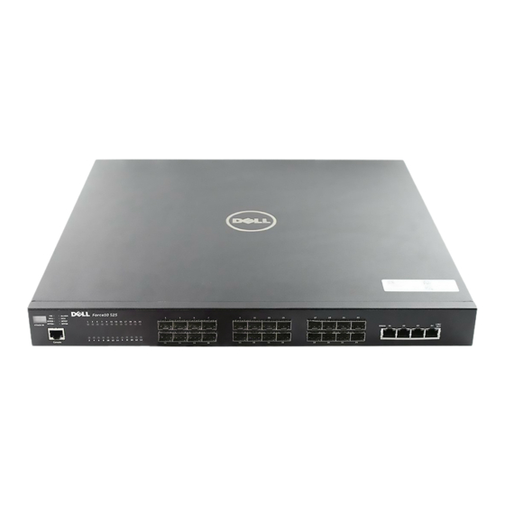
Accessing the Console Port Step Task Install a straight-through RJ-45 copper cable (a standard Ethernet cable) between your system and the console port of the S-Series switch. The console port is at the far left of the faceplate. Turn on the switch by connecting it to power (there is no on/off button). After the switch boots up (the status messages stop), press Enter twice to get the EXEC mode prompt. -
Page 3: Setting Up Passwords
Setting Up Passwords Step Task Command Syntax Command Mode enable Go from EXEC mode to EXEC privilege mode, commonly EXEC called enable mode. After you enter and press Enter, enable the prompt changes to: Force10# config Go from EXEC privilege mode to CONFIGURATION mode. EXEC privilege The prompt changes to: Force10(conf)# Create a password for remote access (through Telnet). - Page 4 Setting Up Layer 2 Switching Step Task Command Syntax Command Mode Select all ports. interface range gi 0/1 - 24 CONFIGURATION (A space is required before and This example assumes that the stack ID is 0. after the dash in the command.) The prompt changes to: Force10(conf-if-range-gi-0/1-24)# switchport...
- Page 5 Managing the Buffer Profile and Setting up Flow Control Buffer profile management, also called buffer tuning or buffer carving, enables you to modify the way your switch allocates buffers from its available memory, and helps prevent packet drops during a temporary burst of traffic.
- Page 6 Figure 2 Defining a Buffer Profile for ASIC Queues [in bytes] buffer-profile fp eql-hig buffer dedicated queue0 3 queue1 3 queue2 3 queue3 3 queue4 3 queue5 3 queue6 3 queue7 3 buffer dynamic 1257 Force10# Figure 3 Configuring Internal ASIC Buffers in Stack Unit 0 buffer fp-uplink stack-unit 0 port-set 0 buffer-policy eql-hig buffer fp-uplink stack-unit 0 port-set 1 buffer-policy eql-hig Force10#...
- Page 7 To apply the configuration, above, to other stack members, use the following commands. The interface range used and port-pipes (“ ”) designated would depend on the S-Series model. The following port-set 0-1 sequence presumes that the subject stack member is an S25P model. For an example of configuring an S50N model, see Basic Layer 2 Setup and Buffer Tuning of the S50N for Storage Environments.
- Page 8 Basic Layer 2 Setup and Buffer Tuning of the S25P for Storage Environments...
Need help?
Do you have a question about the Force10 S25-01-GE-24P and is the answer not in the manual?
Questions and answers