Dell Force10 S2410-01-10GE-24P Manual
Installing the s2410 system
Hide thumbs
Also See for Force10 S2410-01-10GE-24P:
- Command reference manual (514 pages) ,
- Configuration manual (306 pages) ,
- Quick start manual (31 pages)
Table of Contents
Advertisement
Quick Links
Advertisement
Table of Contents

Related Manuals for Dell Force10 S2410-01-10GE-24P


Summary of Contents for Dell Force10 S2410-01-10GE-24P
- Page 1 Installing the S2410 System...
- Page 2 © 2010 Dell Force10. All rights reserved. Reproduction of these materials in any manner whatsoever without the written permission of Dell Inc. is strictly forbidden. Trademarks used in this text: Dell™, the DELL logo, Dell Precision™, OptiPlex™, Latitude™, PowerEdge™, PowerVault™, ®...
-
Page 3: Table Of Contents
Contents 1 About this Guide Information Symbols and Warnings ........5 Related Publications . - Page 4 Chassis Physical Design..........27 Environmental Parameters .
-
Page 5: About This Guide
About this Guide This guide provides site preparation recommendations, step-by-step procedures for rack mounting and desk mounting, inserting optional modules, and connecting to a power source, for the S2410 system, including the S2410CP and S2410P. After you have completed the hardware installation and power-up of the S2410, refer to the SFTOS™ Configuration Guide for the S2410 for software configuration information and the SFTOS Command Reference, Version 2.4 for detailed Command Line Interface (CLI) information. -
Page 6: Related Publications
Related Publications For more information about the S2410, refer to the following documents: • SFTOS Configuration Guide, Version 2.4.1 • SFTOS Command Reference, Version 2.4.1 • S2410 Quick Reference • S-Series and SFTOS Version 2.4.1 Release Notes Each of these documents are available on the S2410 Documentation CD-ROM and on the iSupport website (registration for access to some sections is required): http://www.force10networks.com/csportal20/ KnowledgeBase/Documentation.aspx... -
Page 7: The S2410 System
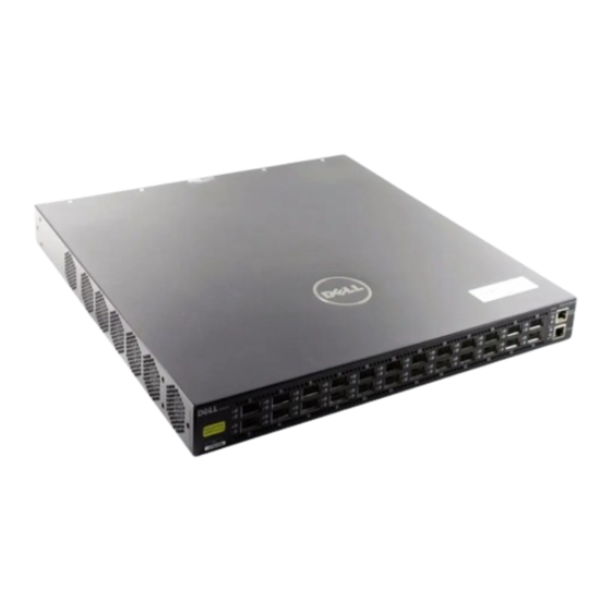
System Status on page 9 Physical Interfaces The Dell Force10 S2410 is a Layer 2 switch that is available in two models — the S2410CP and the S2410P. The primary difference is that the S2410P contains 24 built-in 10-gigabit Ethernet (10G) XFP ports, while the S2410CP contains 20 built-in 10G BaseCX4 ports and four 10G XFP ports. -
Page 8: Features
• At least one cable (included) to connect the power source to the S2410 AC power supply • Brackets and screws (included) for front-mounted rack installation (#2 Phillips screwdriver required but not included) • Console port: Rollover cable (RJ-45 connector) and terminal adapter (DB-9 to RJ-45) (supplied) (For pinout and terminal settings, see Accessing the Console Port on page 23.) -
Page 9: System Status
System Status S2410 status data can be derived in several ways, including physical LED displays, discussed next, along show with boot menu options, CLI commands, SNMP traps, and the SFTOS Web User Interface. For details on those options, see the S2410 Quick Reference, the SFTOS Command Reference (SFTOS 2.4), and the SFTOS Configuration Guide (SFTOS 2.4). - Page 10 The S2410 System...
-
Page 11: Site Preparation
Site Preparation This chapter describes requirements and site setup procedures for your S2410 system. This chapter covers the following topics: • Site Selection • Cabinet Placement on page 11 • Rack Mounting on page 12 • Fans and Airflow on page 12 •... -
Page 12: Rack Mounting
There are no DC power or backup power options. Storing Components If you do not install your system and components immediately, Dell Force10 recommends that you properly store the S2410 and all optional components until you are ready to install them. -
Page 13: Tools Required
• Storage temperature should remain constant ranging from -4° to 158° F (-20°C to 70° C). • Storage humidity range should be between 10 to 95% relative humidity, non-condensing • Store on a dry surface or floor, away from direct sunlight, heat, and air conditioning ducts. •... - Page 14 Site Preparation...
-
Page 15: Installing The S2410
Installing the S2410 S2410 systems have no stacking or other optional modules, so, to install the S2410 system, you can simply install the system on a tabletop, in a rack, or in a cabinet, turn it on, and then connect ports. The following options are discussed in this chapter: •... -
Page 16: Two-Post Rack Mounting
The lower right corner of Figure 4-1 shows the positioning of the rack ears and screws. Note that the rack ears supplied with the S2410 have a hole in the middle to accommodate the vent in the S2410. Figure 4-1. Attaching Rack Ears to Switch Two-Post Rack Mounting Ensure that there is adequate clearance surrounding the rack to permit access and airflow (see Chapter ,... -
Page 17: Four-Post Rack-Mounting With Threaded Rails
Figure 4-2. S2410 Two-post (Front-mounted) Rack-mounting Four-Post Rack-mounting with Threaded Rails Ensure that there is adequate clearance surrounding the cabinet or rack to permit access and airflow. If you are installing two S2410 systems side-by-side, position the two S2410 chassis at least 5 inches (12.7 cm) apart to permit proper airflow. - Page 18 Step Task Insert the S2410 into the rack, and secure the chassis to the front post with two screws. Then secure the chassis to the rear posts with two screws. Figure 4-4. Four-post Rack-mounting with Adjustable Rear-mounting Brackets, Step 2 Set the adjustable rear mounting bracket to the length (one of three lengths) for your bracket.
-
Page 19: Four-Post Rack-Mounting With Cage Nuts
Four-Post Rack-mounting with Cage Nuts Ensure that there is adequate clearance surrounding the cabinet or rack to permit access and airflow. If you are installing two S2410 systems side-by-side, position them at least 5 inches (12.7 cm) apart. Attach the rack ears first, using only the supplied screws (see Attaching the Rack Ears on page 15), and then follow the steps below to install the S2410 chassis into a four-post rack mounting with cage nuts. - Page 20 Step Task Position the cage nuts over the holes on each bracket flange and each rack post. Figure 4-8. Four-post Rack-mounting with Cage Nuts, Step 4 Align the rack filler panel to the rear bracket and rack posts. Secure by inserting two screws into the hole in the filler panel through to the holes in the rack post.
-
Page 21: Supplying Power
Supplying Power NOTE: The power supply cord is used as the main disconnect device; ensure that the socket-outlet is located/ installed near the equipment and is easily accessible. Both S2410 models (S2410CP and S2410P) provide built-in dual AC power supplies. Only one power supply is needed for the unit to operate. - Page 22 Installing the S2410...
-
Page 23: Accessing Ports
Accessing Ports This chapter contains the following sections: • Accessing the Console Port • Accessing the Ethernet Management Port on page 24 • Accessing CX4 Ports on page 24 • Accessing XFP Ports on page 25 Accessing the Console Port You must first connect the console port to a management terminal in order to use the Command Line Interface (CLI) to set up alternative management interfaces, such as an SFTOS Web User Interface connection to the Ethernet Management port (see... -
Page 24: Accessing The Ethernet Management Port
CX4 cables are not included with the S2410, but Dell Force10 has certified cables to use with the S2410. For a list of approved cables, see the S2410 data sheet: http://www.force10networks.com/products/s2410.asp... -
Page 25: Required Cx4 Cable Housing Clearances
Accessing XFP Ports Dell Force10 offers various types of XFP transceivers. For details, see: http://www.force10networks.com/products/specifications.asp All ports in the S2410P use XFP transceivers except the dedicated Ethernet Management port, and the S2410CP includes four XFP ports. - Page 26 CAUTION: Before connecting a transceiver to a source, check the receive power of the transceiver with an optical power meter. Generally, Dell Force10 specified optics are not to be subjected to receive power higher than that stipulated by the optic specification. If the optic is exposed to optical power in excess of the specification, there is a high likelihood that it will be damaged.
-
Page 27: S2410 Specifications
S2410 Specifications Chassis Physical Design Parameter Specifications Height Standard 1U chassis height: 1.73 inches (4.4 cm) Width 17 inches (432 mm) Depth 16.73 inches (425 mm) Weight (with factory-installed components) 12 pounds (5.5 kg) Rack Clearance Required Front: 5-inches (12.7 cm) Rear: 5-inches (12.7 cm) Environmental Parameters Parameter... -
Page 28: Power Supply
Properly shielded and grounded cables and connectors must be used in order to meet FCC emission limits. Dell Force10 is not responsible for any radio or television interference caused by using other than recommended cables and connectors or by unauthorized changes or modifications in the equipment. -
Page 29: Safety Standards And Compliance Agency Certifications
(VCCI). If this equipment is used in a domestic environment, radio disturbance may arise. When such trouble occurs, the user may be required to take corrective actions. WARNING: AC Power cords are for use with Dell Force10 equipment only. Do not use Dell Force10 AC power cords with any unauthorized hardware. -
Page 30: Electromagnetic Compatibility (Emc)
Force10 encourages owners of information technology (IT) equipment to responsibly recycle their equipment when it is no longer needed. Dell Force10 offers a variety of product return programs and services in several countries to assist equipment owners in recycling their IT products. - Page 31 EEE on the environment and human health due to the potential presence of hazardous substances in EEE. Dell Force10 products, which fall within the scope of the WEEE, are labeled with the crossed-out wheelie-bin symbol, as shown above, as required by WEEE.
- Page 32 Customer participation is important to minimize any potential effects of batteries and accumulators on the environment and human health due to the potential presence of hazardous substances. For proper collection and treatment, contact your local Dell Force10 representative. Figure 6-3. The European WEEE symbol For California: —...
-
Page 33: Technical Support
Requesting a Hardware Replacement on page 35 The iSupport Website The iSupport website provides a range of documents and tools to assist you with effectively using Dell Force10 equipment and mitigating the impact of network outages. Through iSupport you can obtain technical information regarding Dell Force10 products, access to software upgrades and patches, and open and manage your Technical Assistance Center (TAC) cases. -
Page 34: Contacting The Technical Assistance Center
Contacting the Technical Assistance Center How to Contact Dell Force10 Log in to iSupport at http://www.force10networks.com/support/, and select the Service Request tab. Managing Your Case Log in to iSupport, and select the Service Request tab to view all open cases and RMAs. -
Page 35: Requesting A Hardware Replacement
• Using the Create Service Request form on the iSupport page (see Contacting the Technical Assistance Center on page 34). • Contacting Dell Force10 directly by E-mail or by phone (see Contacting the Technical Assistance Center on page 34). Provide the following information when using E-mail or phone: •... - Page 36 Technical Support...
- Page 37 Index 12, 15, 25 acoustic noise Ethernet Management Port 8, 9, 24 Agency Compliance Ethernet Management port alarm LED European WEEE Directive alternative management interfaces altitude, maximum fan replacement fan status back-pressure support fans 8, 12 battery removal fans and ventilation battery, lithium flow control baud rate...
- Page 38 Maximum altitude S2410 Web User Interface Maximum Thermal Output Safety Standards mounting brackets screws for rack installation serial baudrate command serial number, switch noise, acoustic Serial Numbers, Locating show tech-support serviceable parts 5, 28 SFTOS Web User Interface 9, 23 shock and vibration optical port warning show commands...
- Page 39 user-serviceable parts Using CX4 Ports Using XFP Ports ventilation voltage Warning Web UI Web User Interface, SFTOS WEEE 30, 32 width of chassis XFP Installation XFP Ports, Using Index...
- Page 40 Index...
- Page 42 Printed in the U.S.A. w w w . d e l l . c o m | s u p p o r t . d e l l . c o m...
Need help?
Do you have a question about the Force10 S2410-01-10GE-24P and is the answer not in the manual?
Questions and answers