Table of Contents
Advertisement
VisionPRO
HOME
COOL
OFF
pm
APPLICATION
The VisionPRO® 8000 with RedLINK™ features an
effortless, 7-Day programmable touchscreen thermostat
that provides control of temperature, humidification,
dehumidification, and ventilation for up to 4 Heat/2 Cool
heat pump systems or up to 3 Heat/2 Cool conventional
systems for residential and commercial applications.
FEATURES
• RedLINK™ Compatible
Increase your content and profit per job by including
RedLINK™ accessories that meet your customers'
comfort and convenience needs. RedLINK accessories
include the Wireless Outdoor Sensor, Portable Comfort
Control (PCC), Equipment Interface Module (EIM),
RedLINK Internet Gateway, Wireless Indoor Sensor,
TrueZONE™ zoning panel with Wireless Adapter, Vent
Boost Remote and Entry/Exit Remote.
• Also Compatible with Equipment Remote Module
(ERM) ERM5220R
• Customizable Service Reminders
Set up to 10 service reminders. Choose from the pre-set
options or customize your own. Reminders can be
based on date or the outdoor temperature.
®
8000 with RedLINK™
• Sensor Inputs
• User Interaction Log
• Selectable for Residential and Light Commercial
• MicroSD Card Port for Quick Installer Setup
• Selectable Sensors
Thermostat - S1
EIM - S1, S2, S3, S4
Assignable inputs allow you to setup Indoor and
Outdoor Temperature Sensors, Discharge and Return
Air Sensors or Dry Contact Devices. Dry Contact
Devices can be used to trip pre-set or customized alerts
on the thermostat home screen. Note: Dry Contact
Alerts require an Equipment Interface Module (EIM).
The interaction log stores history of thermostat setting
changes including temperature, system and installer
setup. You can use the interaction log to save time by
determining if the issue is a system error or an acciden-
tal user error. The Interaction Log is only viewable on a
computer after you download it from the thermostat to
a microSD card.
Applications
One thermostat does it all to meet the needs of Resi-
dential and Light Commercial applications. Simply
select Residential or Commercial during the installer
setup. If Commercial is selected, the thermostat will use
commercial language, meet building codes and offer
365 day holiday scheduling.
Save time by using a microSD card to upload installer
settings and service reminders in one simple step.
When paired with a Wireless Indoor Sensor(s) you have
the ability to choose which sensor(s) to use for tem-
perature, humidification and dehumidification. They
can be used in combination for temperature averag-
ing—or individually—to condition humidity levels in
separate spaces.
PRODUCT DATA
68-0312-06
Advertisement
Table of Contents

Subscribe to Our Youtube Channel
Related Manuals for Honeywell Home VisionPRO 8000


Summary of Contents for Honeywell Home VisionPRO 8000
-
Page 1: Application
® VisionPRO 8000 with RedLINK™ PRODUCT DATA • Sensor Inputs Thermostat - S1 EIM - S1, S2, S3, S4 Assignable inputs allow you to setup Indoor and Outdoor Temperature Sensors, Discharge and Return Air Sensors or Dry Contact Devices. Dry Contact Devices can be used to trip pre-set or customized alerts on the thermostat home screen. -
Page 2: Table Of Contents
® VISIONPRO 8000 WITH REDLINK™ CONTENTS Application ............. Installer Options .................... 72 Using the Temperature Display ..............72 Features ............Using the Humidity Display ............... 72 Specifications ..........Outputs (U1, U2, U3) ................... 73 System Installation ........Inputs (S1, S2, S3, S4) ................73 When Installing this Product... -
Page 3: Specifications
® VISIONPRO 8000 WITH REDLINK™ SPECIFICATIONS Power Consumption of TH8321/TH8320/TH8110: Backlight on: 1.44 VA Backlight off: 1.32 VA Thermostat Description: RedLINK Communication: Feature Description Frequency: 900 Mhz frequency range Powering method • Common wire or battery Re-Sync Time: RedLINK devices re-establish communica- tion within 6 minutes after AC power resumes. - Page 4 ® VISIONPRO 8000 WITH REDLINK™ 6-5/32 (156) 25/32 (20) 5-3/4 4-5/8 (146) (118) 1-1/2 (38) 1-1/8 (29) 4-15/16 (126) M34258 Fig. 2. Dimensions of VisionPRO cover plate in in. (mm). 1-19/32 4-53/64 (123) (41) 8-7/8 (225) 3-5/16 (84) M34521 9-11/32 Fig.
- Page 5 ® VISIONPRO 8000 WITH REDLINK™ Table 1. (Continued) Operating Ambient Operating Relative Shipping Physical Dimensions in in. Product Part Number Temperature Humidity Temperature (mm) Color(s) Wireless Vent and Filter HVC20A1000 32 to 120 °F 5% to 90% -20 to 120 °F 3-15/16 x 1-15/16 x 5/8 Arctic Boost Remote...
- Page 6 ® VISIONPRO 8000 WITH REDLINK™ Table 1. (Continued) Operating Ambient Operating Relative Shipping Physical Dimensions in in. Product Part Number Temperature Humidity Temperature (mm) Color(s) Discharge or Return Air C7770A1006 45 to 99 °F 5% to 95% -40 to 150 °F Probe: 6 x 1/4 Sensor (7 to 37 °C)
-
Page 7: System Installation
® VISIONPRO 8000 WITH REDLINK™ SYSTEM INSTALLATION When Installing this Product... 1. Read these instructions carefully. Failure to follow the instructions can damage the product or cause a haz- ardous condition. 2. Check the ratings given in the instructions to make sure the product is suitable for your application. -
Page 8: Installation Options
® VISIONPRO 8000 WITH REDLINK™ INSTALLATION OPTIONS The VisionPRO® 8000 with RedLINK™ system can be wired directly to the equipment, used with an Equipment Interface Module, or with a TrueZONE wireless adapter. If using the Equipment Interface Module, see “Installing Equipment Interface Module (if used)” on page 9. If using a TrueZONE wireless adapter, follow the installation instructions that came with the TrueZONE panel, and go to “Selecting Thermostat Location”... -
Page 9: Guidelines For Installing Redlink Devices
® VISIONPRO 8000 WITH REDLINK™ Guidelines for Installing RedLINK The Equipment Interface Module (EIM) can be mounted vertically on the HVAC equipment or on a wall in the Devices equipment room. — When installing more than one Thermostat and 1. Mount the EIM near the HVAC equipment, or on the Equipment Interface Module, mount the Equipment equipment itself. -
Page 10: Selecting Discharge And Return Air Temperature Sensor Mounting Locations
® VISIONPRO 8000 WITH REDLINK™ Selecting Discharge and Return Air Temperature Sensor Mounting Locations ALTERNATE MOUNTING LOCATION FOR DISCHARGE SENSOR. Refer to the guidelines below and Fig. 8–12 for mounting STEAM OR locations of the Discharge and Return Air Temperature POWERED Sensors. -
Page 11: Installing Discharge And Return Air Temperature Sensors
® VISIONPRO 8000 WITH REDLINK™ 3. Connect wires to S1, S2, S3 or S4 terminals at the EIM. 4. Setup the S1, S2, S3 or S4 terminals in the Installer Setup at the thermostat. MOUNT DISCHARGE BYPASS SENSOR HERE HUMIDIFIER MOUNT DOWNSTREAM OF BYPASS... -
Page 12: Installing Wallplate
® VISIONPRO 8000 WITH REDLINK™ Installing Wallplate Installing VisionPRO® 8000 with RedLINK™ CAUTION Connect Power Electrical Hazard. 1. Insert supplied AA alkaline batteries for primary or Can cause electrical shock or equipment damage. backup power. Disconnect power before wiring. NOTE: For best RedLINK performance, mount thermo- stats at least 2 feet apart. -
Page 13: Remove Coin Cell Battery Tab
® VISIONPRO 8000 WITH REDLINK™ CONVENTIONAL Fig. 21. Remove coin cell battery tab. HEAT PUMP Mounting Thermostat on Wallplate Fig. 19. Thermostat wired directly to equipment. 1. If your thermostat has hinges along the bottom and a IF THE THERMOSTAT IS USED WITH AN EQUIPMENT button on the top, align the thermostat at the bottom INTERFACE MODULE OR TRUEZONE WIRELESS and snap into place as shown. -
Page 14: Performing Initial Setup
® VISIONPRO 8000 WITH REDLINK™ Portable Comfort Control TrueSTEAM (Obsolete) 1. Install 3 fresh AA alkaline batteries. 1. Wire and power TrueSTEAM. 2. Connect the ABCD terminals between TrueSTEAM and the THM4000 Wireless Adapter. 3. Adjust the DIP Switches on TrueSTEAM as follows when using the Wireless Adapter: •... -
Page 15: Linking Thermostat To Equipment Interface Module (If Used)
® VISIONPRO 8000 WITH REDLINK™ 1. Follow prompts on the screen to select the appropri- Green Flashing: In Listening Mode - system ate options. is ready to add RedLINK devices. Green Steady: RedLINK devices are commu- nicating. Red: RedLINK device(s) are NOT communi- cating. -
Page 16: Completing Initial Setup
® VISIONPRO 8000 WITH REDLINK™ The thermostat now displays its Home screen and the thermostat setup is complete. Press Connect on New Accessories. Fig. 35. Thermostat in listening mode. 3. After a short delay (up to 15 seconds), check thermo- stat to confirm the connection of each RedLINK ... -
Page 17: Locating The Connect Buttons On Redlink Accessories
® VISIONPRO 8000 WITH REDLINK™ 4. Select Wireless Manager. 7. After a short delay (up to 15 seconds), check thermo- stat to confirm the connection of each RedLINK or accessory. Touch to review the list. 8. Touch Done at the thermostat after all new RedLINK accessories are connected. - Page 18 ® VISIONPRO 8000 WITH REDLINK™ 3. Press “No” at the next screen to save and exit, or press RedLINK Internet Gateway “Yes” if you need to connect additional thermostats to 1. Press and quickly release the button on the Internet the Portable Comfort Control.
- Page 19 ® VISIONPRO 8000 WITH REDLINK™ Wireless Indoor Sensor 4. Select the Indoor Sensor name from the list and press Done. The Indoor Sensor names are used when 1. Press and quickly release the CONNECT button. After selecting which sensor to use for temperature con- a short delay, the status light (see Fig.
-
Page 20: Finding Your Password (Date Code) To Access Installer Options
® VISIONPRO 8000 WITH REDLINK™ NOTE: The thermostat can work with up to 6 Vent Boost Thermostat Password (Date Code) remotes. Finding Your Password (Date Code) to Access Installer Options You need a password (Date Code) to access Installer Options. Installer Options allow you to: RoHs Compliant Conformité... -
Page 21: Make Changes To Installer Setup
® VISIONPRO 8000 WITH REDLINK™ Table 2. Installer Options. Menu Item Description Installer Options Installer Setup Select INSTALLER SETUP to set system settings one by one. Installer Test Select INSTALLER TEST to quickly determine if the heat, cool, fan and thermostat are operating properly. - Page 22 ® VISIONPRO 8000 WITH REDLINK™ Table 3. Installer Setup (ISU) Table. (Continued) Residential, Installer Setup Commercial Requires Number Name Settings Default or Both Notes Outdoor Air Sensor Both This ISU automatically defaults to Yes when a Wireless Outdoor Sensor is connected. An Outdoor Sensor is required to set the following ISUs: ISU 312 Outdoor Temperature Lockouts (Heat...
- Page 23 ® VISIONPRO 8000 WITH REDLINK™ Table 3. Installer Setup (ISU) Table. (Continued) Residential, Installer Setup Commercial Requires Number Name Settings Default or Both Notes None Geo Forced Air Heating and Both This thermostat has the capability of controlling Cooling Only Cooling Geothermal Radiant Heat, Geothermal Forced Air and Backup Heat.
- Page 24 ® VISIONPRO 8000 WITH REDLINK™ Table 3. Installer Setup (ISU) Table. (Continued) Residential, Installer Setup Commercial Requires Number Name Settings Default or Both Notes None Cool Stage 4 Default varies Commercial Cool Stage 4 is only available if ISU 101 is based on Commercial.
- Page 25 ® VISIONPRO 8000 WITH REDLINK™ Table 3. Installer Setup (ISU) Table. (Continued) Residential, Installer Setup Commercial Requires Number Name Settings Default or Both Notes Run Backup Heat Both This ISU is only displayed when ISU 201 Heating with Primary Equipment is Other. When ISU 201 Heating Equipment is Other, you can select how the Backup Heat operates.
- Page 26 ® VISIONPRO 8000 WITH REDLINK™ Table 3. Installer Setup (ISU) Table. (Continued) Residential, Installer Setup Commercial Requires Number Name Settings Default or Both Notes None A-L/A Terminal None Commercial This ISU is only displayed when ISU 101 Time Of Day “Econ.
- Page 27 ® VISIONPRO 8000 WITH REDLINK™ Table 3. Installer Setup (ISU) Table. (Continued) Residential, Installer Setup Commercial Requires Number Name Settings Default or Both Notes 2° F to 9° F (in 1° F increments) Auto Changeover 3° F Both This ISU is only displayed when ISU 300 is set to Deadband Automatic.
- Page 28 ® VISIONPRO 8000 WITH REDLINK™ Table 3. Installer Setup (ISU) Table. (Continued) Residential, Installer Setup Commercial Requires Number Name Settings Default or Both Notes Comfort Cool Differential Comfort Both ISU 301 Control Options must be set to Advanced Stage 2 1.0°...
- Page 29 ® VISIONPRO 8000 WITH REDLINK™ Table 3. Installer Setup (ISU) Table. (Continued) Residential, Installer Setup Commercial Requires Number Name Settings Default or Both Notes Comfort Heat Differential Comfort Both ISU 301 Control Options must be set to Advanced 1.0° F to 3.5° F from setpoint (in Stage 2 to view or adjust this ISU.
- Page 30 ® VISIONPRO 8000 WITH REDLINK™ Table 3. Installer Setup (ISU) Table. (Continued) Residential, Installer Setup Commercial Requires Number Name Settings Default or Both Notes Comfort Compressor Heat Comfort Both ISU 301 Control Options must be set to Advanced Diff. Stage 2 1.0°...
- Page 31 ® VISIONPRO 8000 WITH REDLINK™ Table 3. Installer Setup (ISU) Table. (Continued) Residential, Installer Setup Commercial Requires Number Name Settings Default or Both Notes Outdoor Lockout Both ISU 312 Heat Pump Outdoor Lockout requires an 5° F to 60° F (in 5° F increments) Heat Pump outdoor sensor.
- Page 32 ® VISIONPRO 8000 WITH REDLINK™ Table 3. Installer Setup (ISU) Table. (Continued) Residential, Installer Setup Commercial Requires Number Name Settings Default or Both Notes 1 to 6 CPH Cool / Compressor Both This ISU is only displayed when ISU 207 Cool / Cycles Per Hour Compressor Stages is set to 1 stage.
- Page 33 ® VISIONPRO 8000 WITH REDLINK™ Table 3. Installer Setup (ISU) Table. (Continued) Residential, Installer Setup Commercial Requires Number Name Settings Default or Both Notes 1 to 12 CPH Heat Cycles Per Conv. Forced Air Both This ISU is only displayed when ISU 207 Heat Hour Stage 1 = 5 CPH Stages is set to 1 stage.
- Page 34 ® VISIONPRO 8000 WITH REDLINK™ Table 3. Installer Setup (ISU) Table. (Continued) Residential, Installer Setup Commercial Requires Number Name Settings Default or Both Notes 1 to 12 CPH Heat Cycles Per Conv. Forced Air Both This ISU is only displayed when ISU 207 Heat Hour Stage 3 = 5 CPH Stages is set to 3 stages.
- Page 35 ® VISIONPRO 8000 WITH REDLINK™ Table 3. Installer Setup (ISU) Table. (Continued) Residential, Installer Setup Commercial Requires Number Name Settings Default or Both Notes 1 to 12 CPH Backup Heat Cycles Electric = Both This ISU is only displayed when ISU 207 or 213 Per Hour Stage 2 9 CPH Backup Heat Stages is set to 2 stages.
- Page 36 ® VISIONPRO 8000 WITH REDLINK™ Table 3. Installer Setup (ISU) Table. (Continued) Residential, Installer Setup Commercial Requires Number Name Settings Default or Both Notes Standard: Standard Type of Override Standard Commercial The system maintains temperatures Initiate Occupancy programmed for the occupied and unoccupied time periods.
- Page 37 ® VISIONPRO 8000 WITH REDLINK™ Table 3. Installer Setup (ISU) Table. (Continued) Residential, Installer Setup Commercial Requires Number Name Settings Default or Both Notes Min. Heat Recovery 0° F Commercial Off: The heating system will begin recovery at the -20° F to 100°F Outdoor Temp time that is scheduled.
- Page 38 ® VISIONPRO 8000 WITH REDLINK™ Table 3. Installer Setup (ISU) Table. (Continued) Residential, Installer Setup Commercial Requires Number Name Settings Default or Both Notes Max. Heat Recovery 40° F Commercial Off: The heating system will begin recovery at the Outdoor Temp -20°...
- Page 39 ® VISIONPRO 8000 WITH REDLINK™ Table 3. Installer Setup (ISU) Table. (Continued) Residential, Installer Setup Commercial Requires Number Name Settings Default or Both Notes Min. Cool Recovery 90° F Commercial Off: The cooling system will begin recovery at the -20° F to 100° F Outdoor Temp time that is scheduled.
- Page 40 ® VISIONPRO 8000 WITH REDLINK™ Table 3. Installer Setup (ISU) Table. (Continued) Residential, Installer Setup Commercial Requires Number Name Settings Default or Both Notes Max. Cool Recovery 70° F Commercial Off: The cooling system will begin recovery at the Outdoor Temp -20°...
- Page 41 ® VISIONPRO 8000 WITH REDLINK™ Table 3. Installer Setup (ISU) Table. (Continued) Residential, Installer Setup Commercial Requires Number Name Settings Default or Both Notes None Residential: 70° F Both The thermostat maintains this Heat setting when 40° F to 90° F Entry / Exit Remote the user presses Home / Occupied at the Entry / - Home Heat...
- Page 42 ® VISIONPRO 8000 WITH REDLINK™ Table 3. Installer Setup (ISU) Table. (Continued) Residential, Installer Setup Commercial Requires Number Name Settings Default or Both Notes Wired Discharge Both The thermostat will not display the Wired Sensor Discharge Sensor option if there is no fan in the system.
- Page 43 ® VISIONPRO 8000 WITH REDLINK™ Table 3. Installer Setup (ISU) Table. (Continued) Residential, Installer Setup Commercial Requires Number Name Settings Default or Both Notes None Discharge Sensor None Both Select the terminals wired to the Discharge Sensor. Number of Sensor Inputs: Thermostat = S1 Equipment Interface Module = S1, S2, S3 and S4 Discharge Sensor...
- Page 44 ® VISIONPRO 8000 WITH REDLINK™ Table 3. Installer Setup (ISU) Table. (Continued) Residential, Installer Setup Commercial Requires Number Name Settings Default or Both Notes Fan Failure Dry Both Dry Contact Alerts require an Equipment Interface Contact Alert Module. This ISU is only displayed if an S1-S4 terminal is available.
- Page 45 ® VISIONPRO 8000 WITH REDLINK™ Table 3. Installer Setup (ISU) Table. (Continued) Residential, Installer Setup Commercial Requires Number Name Settings Default or Both Notes 50° F to 70° F Remote Setback 64° F Commercial Remote Setback requires an EIM (Equipment Heat Setpoint Interface Module).
- Page 46 ® VISIONPRO 8000 WITH REDLINK™ Table 3. Installer Setup (ISU) Table. (Continued) Residential, Installer Setup Commercial Requires Number Name Settings Default or Both Notes Normally Open Water Leak Alert is Normally Open Both Dry Contact Alerts require an EIM (Equipment [See Settings] Normally Closed Interface Module).
- Page 47 ® VISIONPRO 8000 WITH REDLINK™ Table 3. Installer Setup (ISU) Table. (Continued) Residential, Installer Setup Commercial Requires Number Name Settings Default or Both Notes N.O. when Fan Runs Fan Failure Alert is N.C. when Fan Both Dry Contact Alerts require an EIM (Equipment N.C.
- Page 48 ® VISIONPRO 8000 WITH REDLINK™ Table 3. Installer Setup (ISU) Table. (Continued) Residential, Installer Setup Commercial Requires Number Name Settings Default or Both Notes Air Filter 2 Both Reminder Run Time: 10, 20, 30, 45, 60, 90, 120, 150 days Calendar: 30, 45, 60, 75 days 3, 4, 5, 6, 9, 12, 15 months...
- Page 49 ® VISIONPRO 8000 WITH REDLINK™ Table 3. Installer Setup (ISU) Table. (Continued) Residential, Installer Setup Commercial Requires Number Name Settings Default or Both Notes User Humidifier in Heat Mode - No User Humidifier in User Humidifier Both Heat: Includes Heat, Emergency Heat and Auto. If or Yes Heat Mode in Heat Mode -...
- Page 50 ® VISIONPRO 8000 WITH REDLINK™ Table 3. Installer Setup (ISU) Table. (Continued) Residential, Installer Setup Commercial Requires Number Name Settings Default or Both Notes Change to: Sensor for Dehum T-Stat Sensor Both Select a sensor to control dehumidification T-Stat Sensor (thermostat or an optional remote sensor).
- Page 51 ® VISIONPRO 8000 WITH REDLINK™ Table 3. Installer Setup (ISU) Table. (Continued) Residential, Installer Setup Commercial Requires Number Name Settings Default or Both Notes 5 to 15 minutes Dehum Minimum 10 minutes Commercial This ISU is only displayed if ISU 908 Dehum On Time Control is set to Minimum On Time.
- Page 52 ® VISIONPRO 8000 WITH REDLINK™ Table 3. Installer Setup (ISU) Table. (Continued) Residential, Installer Setup Commercial Requires Number Name Settings Default or Both Notes Automatic Dehum Away Mode Automatic Both The On and Circulate settings may re-introduce Fan Setting humidity into the living space. Circulate 70°...
- Page 53 ® VISIONPRO 8000 WITH REDLINK™ Table 3. Installer Setup (ISU) Table. (Continued) Residential, Installer Setup Commercial Requires Number Name Settings Default or Both Notes 1000 to 5000 sq. ft. (in 100 sq. ft. 1009 Size of House 1000 sq. feet Residential This ISU is only displayed when ISU 1005 increments)
- Page 54 ® VISIONPRO 8000 WITH REDLINK™ Table 3. Installer Setup (ISU) Table. (Continued) Residential, Installer Setup Commercial Requires Number Name Settings Default or Both Notes 1013 High Outdoor Temp Both Requires an outdoor sensor. Vent Lockout 80° F to 110° F (in 5° F increments) This ISU is only displayed when ISU 1000 Ventilation Type is set to ERV / HRV or Fresh Air...
- Page 55 ® VISIONPRO 8000 WITH REDLINK™ Table 3. Installer Setup (ISU) Table. (Continued) Residential, Installer Setup Commercial Requires Number Name Settings Default or Both Notes On Demand Backlighting On Demand Both Select Continuous or On Demand backlighting. Continuous Select Continuous backlighting if you would like the backlight to be on all the time (C wire is required for Continuous backlighting).
-
Page 56: Installer Tests
® VISIONPRO 8000 WITH REDLINK™ INSTALLER TESTS Using the Equipment Test 1. Select the equipment you want to test and press the Use the installer tests to check out the system: arrow buttons to turn the equipment on/off. Press • Equipment Test: Tests the heating, cooling, fan, and IAQ Back to test the remaining equipment. -
Page 57: Using The Wireless Signal Strength Test
® VISIONPRO 8000 WITH REDLINK™ Using the Wireless Signal Strength MOUNTING OPTIONAL Test ACCESSORIES 1. Select Installer Test (see Fig. 64), then select Wireless Test. Outdoor Sensor Mount the sensor where: • it cannot be tampered with. • there is good air circulation. •... - Page 58 ® VISIONPRO 8000 WITH REDLINK™ C7189U1005 Wired Indoor Sensor Use the following steps to mount the sensor: 1. Remove the cover from the remote sensor (see Fig. 75). M7514 M24056A Fig. 73. Typical locations for C7089U1006 Outdoor Fig. 75. Remove the cover. Sensor.
-
Page 59: Operation
® VISIONPRO 8000 WITH REDLINK™ Entry/Exit Remote or Vent Boost Remote Mounting the remote is optional. 1. Remove the front cover from the remote. 2. Use provided screws and wall anchors to fasten the remote to the wall. Drill 3/16-inch holes for drywall, 7/32-inch for plaster. -
Page 60: Setting The Time/Date
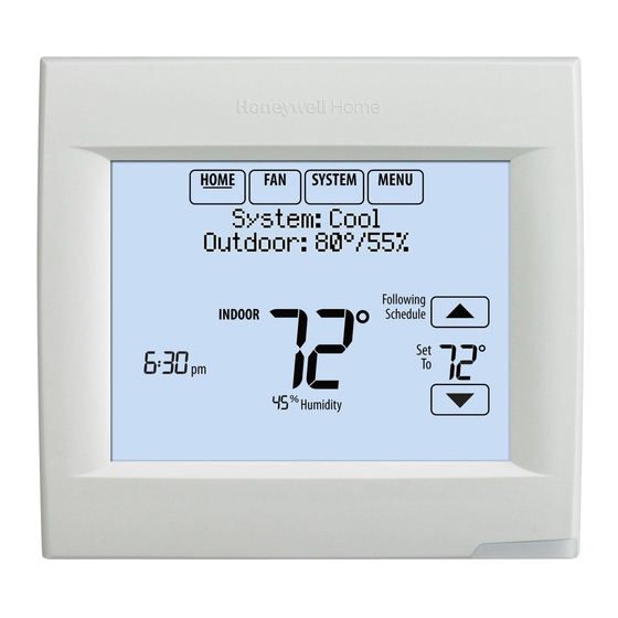
® VISIONPRO 8000 WITH REDLINK™ HOME. Touch to display Home screen. FAN. Select fan mode. SYSTEM. Select system mode (Heat/Cool). MENU. Touch to display options. Start here to set a program schedule. Current status. Shows system mode (heat/cool), outdoor temperature and humidity (with optional outdoor sensor). Override. -
Page 61: Setting The Fan
® VISIONPRO 8000 WITH REDLINK™ Setting the Fan 3. Touch Done to save and exit. NOTE: The Auto and Em Heat system settings may not 1. Touch FAN to display fan settings. appear, depending on how your thermostat was installed. Preset Energy-Saving Schedules MCR34096 These default Energy Saver settings can reduce expenses. -
Page 62: Overriding Schedules: Residential Use
® VISIONPRO 8000 WITH REDLINK™ NOTE: Touch Cancel Period to eliminate any unwanted time period. Touch Fan Setting to customize fan settings for Use Scheduling any time period. Assistant? Overriding Schedules: Residential MCR34102 1. Touch to adjust the temperature (right side of screen) and the Hold Until time (left side). -
Page 63: Viewing Equipment Status
® VISIONPRO 8000 WITH REDLINK™ • Touch Override to use a pre-set occupied temperature if 3. Touch to view the status of all the equipment a person uses the room during an unoccupied period. your thermostat is controlling. Depending on how The new temperature will be maintained for 1 hour and your thermostat was installed, the Equipment Status can be adjusted up to the maximum time set by the... -
Page 64: Setting Holiday/Event Schedules: Commercial Use
® VISIONPRO 8000 WITH REDLINK™ 4. Review your selections on the last display, and touch 4. Make selections as prompted on each screen. For Done to save your settings. Touch Cancel to ignore more information, see next two pages. the changes. 5. -
Page 65: Setting Holiday Schedule: Commercial Use
® VISIONPRO 8000 WITH REDLINK™ 4. Review the settings and touch Done to save them. 4. Touch to select the Heat and Cool tempera- Touch Cancel to ignore the changes. tures. Schedule adjusted Temperature to 62 in heating During Holiday MCR34118 Fig. -
Page 66: Initiating Occupancy Mode: Commercial Use
® VISIONPRO 8000 WITH REDLINK™ 3. Touch to select the Heat and Cool tempera- Remote Setback: Commercial Use tures, then touch Next to select return date. During Occupied program periods, an occupancy sensor directs the thermostat to go to REMOTE SETBACK settings when the room is empty. -
Page 67: Adjusting Dehumidification Settings: Residential Use
® VISIONPRO 8000 WITH REDLINK™ 5. If frost or condensation appears on the windows, 1. Touch MENU and select Dehumidification. press MENU, scroll down and select Window Protec- tion. MCR34100 Fig. 120. Dehumidification Equipment Status Fig. 119. 6. Window Protection is set on a scale from 1–10. A set- ting of 1 represents poorly insulated windows and a MCR34130 setting of 10 represents well insulated windows. -
Page 68: Adjusting Dehumidification Settings: Commercial Use
® VISIONPRO 8000 WITH REDLINK™ Adjusting Dehumidification If your air conditioner is used to control humidity, the thermostat may use the following methods to maintain Settings: Commercial Use humidity: • Cool from 1° to 5° F lower than your temperature This feature can control a dehumidifier or use your air setting. -
Page 69: Ventilation Options
® VISIONPRO 8000 WITH REDLINK™ Ventilation Options Setting Preferences Mode: Preference menu options let you select how the thermostat displays information or responds to certain situations. Auto: Ventilation runs as programmed by the installer. 1. Touch MENU and select Preferences. Off: Ventilation remains off unless turned on using the timer. -
Page 70: Cleaning The Thermostat Screen
® VISIONPRO 8000 WITH REDLINK™ Cleaning the Thermostat Screen Adjusting Security Settings When you select the Clean Screen option, the screen is You can adjust security options to prevent unauthorized locked to prevent accidental changes to the thermostat changes to system settings. while you clean the screen. -
Page 71: Viewing Dealer Information
® VISIONPRO 8000 WITH REDLINK™ Viewing Dealer Information room temperature intersects the compressor ramp, the compressor turns on until the setpoint is reached. If the Check dealer information if you need to contact your room temperature does not rise quickly enough and installer for maintenance, repairs, or upgrades. -
Page 72: Installer Options
® VISIONPRO 8000 WITH REDLINK™ The addition of the integral error is what differentiates the If your system is set up to use remote indoor sensors, it may thermostat from many other mechanical and electronic be reading a sensor in another location. thermostats. -
Page 73: Outputs (U1, U2, U3)
® VISIONPRO 8000 WITH REDLINK™ Outputs (U1, U2, U3) Data Logs U1, U2, U3 are outputs that can be setup to control IAQ The Data Logs collect system information that can help equipment and a stage of heating or cooling in the Installer point a service technician in the right direction when Setup. -
Page 74: Dry Contact Alerts
® VISIONPRO 8000 WITH REDLINK™ Fig. 156. The following dry contact alerts are available. Fig. 154. Full Drain Pan Alert Using the Data Logs When the dry contact device detects that the condensate drain pan is full, the thermostat provides an alert to the To view a data log, you must download the log to a microSD user. -
Page 75: Set Up The Dry Contact Alerts
® VISIONPRO 8000 WITH REDLINK™ Set Up the Dry Contact Alerts WARNING You can connect the S1, S2, S3 and S4 terminals on the Equipment Damage Hazard. EIM to a dry contact device to display an alert. Dry contact Do not apply power to S1, S2, S3 or S4 terminals. Do alerts include Full Drain Pan, Dirty Filter, Water Leak, not connect a temperature sensor to the S1, S2, S3 System Shutdown, Service Needed, Fan Failure and... -
Page 76: Staging Control
® VISIONPRO 8000 WITH REDLINK™ 6. If you are creating a custom alert, type the alert name Heat Differential and press Done. The alert name is what appears on The indoor temperature must drop to the selected the Home screen when the alert is detected. See differential setting before the thermostat will turn on the Fig. - Page 77 ® VISIONPRO 8000 WITH REDLINK™ Backup Heat Droop backup heat earlier when the user raises the set- point. This does NOT apply to heat pumps with A Backup Heat Droop is available for any system with 2 fossil fuel backup heat. heating types.
-
Page 78: Heat Pump And Backup Heat Operation
® VISIONPRO 8000 WITH REDLINK™ Multistage Control To view/adjust “Finish with High Heat Stage” or “Finish with High Cool Stage,” set ISU 301 Control Options to Multistage Control keeps the high stage of the equipment “Advanced Options.” See Fig. 168. Select Yes to turn on this running until the desired setpoint is reached. -
Page 79: Geothermal Radiant Heat
® VISIONPRO 8000 WITH REDLINK™ Alert Light - General (whichever occurs first). Geothermal Forced Air Heat turns off when the Backup Heat turns on. Geothermal Radiant An alert light is located in the lower right corner of the Heat stays on when the Backup Heat turns on. thermostat. -
Page 80: Indoor Air Quality (Iaq) Control
® VISIONPRO 8000 WITH REDLINK™ 4. Select a Geothermal Forced Air Option. For example, 7. Select the Backup Heat Type. See Fig. 175. if Geothermal Forced Air is used for both heating and cooling, select the "Heating and Cooling" option. See Fig. - Page 81 ® VISIONPRO 8000 WITH REDLINK™ your windows during cold outdoor temperatures, poorly 2. If optional remote wireless indoor sensors are insulated windows require a lower Window Protection installed, you can choose which sensor you want to setting, which will limit how much your humidifier can run. use for humidification control.
- Page 82 ® VISIONPRO 8000 WITH REDLINK™ 5. Select the system mode(s) to allow humidification. See Fig. 181. NOTE: Heat includes Heat, Emergency Heat and Auto. If the system is in Auto mode, the ther- mostat will allow humidification if the last call was for heat.
-
Page 83: Dehumidification - Residential
® VISIONPRO 8000 WITH REDLINK™ 2. Select Auto. automatically switch between humidification and dehumidification to maintain the desired humidity level. If humidification and dehumidification are setup Humidification to operate in the same system mode (Heat, Cool, Auto Off) and you are sensing humidity from two differ- ent locations using a remote wireless indoor sen- sor, the thermostat will allow humidification and dehumidification to operate at the same time, and... - Page 84 ® VISIONPRO 8000 WITH REDLINK™ 1. Select the Dehumidification Equipment in ISU 900. 4. Select the terminals wired to the A/C with Low Speed See Fig. 188. Fan. See Fig. 191. Fig. 188. Fig. 191. 2. If optional remote wireless indoor sensors are 5.
- Page 85 ® VISIONPRO 8000 WITH REDLINK™ Dehumidification using a Whole House to display on the home screen. See “Wireless Indoor Sensor” beginning on page 114 for more informa- Dehumidifier tion. The Whole House Dehumidifier option requires a dedicated unit for dehumidification. The thermostat can be set to control dehumidification in all modes (Heat, Off, Cool [ISU 912]).
- Page 86 ® VISIONPRO 8000 WITH REDLINK™ 6. Set Dehumidifier Fan Control settings. See Fig. 199. • Tstat Controls Fan Thermostat turns on the dehumidifier and the fan when dehumidification is needed. • Equip Controls Fan Thermostat turns on the dehumidifier when dehumidification is needed.
- Page 87 ® VISIONPRO 8000 WITH REDLINK™ 2. Set Fan Control settings. See Fig. 204. • Low Limit Temperature Setting • On: Fan is always on. If the cooling system is used to control humidity • Automatic: Fan runs only when cooling system is while Dehumidification Away Mode is active, the thermostat allows the cooling system to lower the •...
-
Page 88: Dehumidification - Commercial
® VISIONPRO 8000 WITH REDLINK™ Control Dehumidification Level midification to operate at the same time, and there is no deadband between humidification and dehu- 1. Touch MENU and select Dehumidification. midification settings. Dehumidification - Commercial MCR34100 The thermostat reads the indoor humidity level and allows the user to set a dehumidification setting. - Page 89 ® VISIONPRO 8000 WITH REDLINK™ Minimum On Time (ISU 908 and 909): This option ensures 1. Select the Dehumidification Equipment in ISU 900. that the compressor runs long enough to effectively reduce See Fig. 210. humidity when the cooling equipment is cycled on. The compressor will run for the minimum “on time”...
- Page 90 ® VISIONPRO 8000 WITH REDLINK™ 4. Select the terminals wired to the A/C with Low Speed Set up Dehumidification With Fan or Hot Gas Bypass. See Fig. 213. Dehumidifier Some screens shown in this section may not appear on the thermostat, depending on how you set up dehumidification.
- Page 91 ® VISIONPRO 8000 WITH REDLINK™ 4. Select the terminals wired to the Dehumidifier. See 6. Set Dehumidifier Fan Control settings. See Fig. 221. Fig. 219. • Tstat Controls Fan Thermostat turns on the dehumidifier and the fan when dehumidification is needed. •...
-
Page 92: Ventilation
® VISIONPRO 8000 WITH REDLINK™ Control Dehumidification Level to operate in the same system mode (Heat, Cool, Off) and you are sensing humidity from two differ- 1. Touch MENU and select Dehumidification. ent locations using a remote wireless indoor sen- sor (for example, main level and crawl space), the thermostat will allow humidification and dehu- midification to operate at the same time, and there... - Page 93 ® VISIONPRO 8000 WITH REDLINK™ • ASHRAE is Priority Set up Ventilation ASHRAE requires additional ventilation following a long Some screens shown in this section may not appear on the off cycle. The thermostat meets the ASHRAE 62.2 thermostat, depending on how you set up ventilation. ventilation standard by running additional ventilation when outdoor conditions are favorable.
- Page 94 ® VISIONPRO 8000 WITH REDLINK™ 4. Select the Ventilation Fan Control. See “Ventilation • Provides % run time that is needed to meet the Fan Control (ISU 1006)” on page 92 for more infor- ASHRAE 62.2 Standard. mation. See Fig. 229. NOTE: ISU 1006 is only displayed if the Ventilation Type is ERV / HRV.
- Page 95 ® VISIONPRO 8000 WITH REDLINK™ 8. If Percent On Time was selected for ISU 1005, select the Ventilation Percent on Time. See Fig. 233. Fig. 232. Fig. 233. 9. Select the Outdoor Condition Lockouts. See Fig. 234. See “Ventilation — Outdoor Condition Lockouts (ISU 1013)”...
- Page 96 ® VISIONPRO 8000 WITH REDLINK™ When ISU 1012 Ventilation Priority is set to Lockouts are mostat will indicate whether this meets or may not Priority, or ISU 1005 Ventilation Control Methods is set to meet the ASHRAE 62.2 Standard or the Percent On Percent On Time, the thermostat will indicate whether Time setting.
-
Page 97: Ventilation Options
® VISIONPRO 8000 WITH REDLINK™ 2. Select Mode, Temporary Boost, or Lockout, then select appropriate options. Lockout in Sleep Period: Mode Temporary Boost MCR34137 MCR34133 Fig. 245. NOTE: If set up for humidification in heat mode, the venti- Fig. 241. lator will turn on to remove excess humidity if 10% or more above your humidity setting. -
Page 98: Customizable Reminders
® VISIONPRO 8000 WITH REDLINK™ 3. Select the reminder you want to set. You can change or create custom reminders in ISU 1200. 4. Press to set the timer length. Ranges, incre- ments, and units will change based on the reminder. NOTE: When set for run time days, the thermostat tracks the amount of time the fan has run and compares that time against the number... - Page 99 ® VISIONPRO 8000 WITH REDLINK™ 4. Press the up or down arrows to set the outdoor tem- 7. When the user touches Press HERE for info on the perature and press Next. Home Screen, the reminder message will be dis- played.
- Page 100 ® VISIONPRO 8000 WITH REDLINK™ 10. To clear the Alert, (and turn off the Red Alert Light on 5. Touch Press HERE to edit to set the reminder mes- the thermostat), select Dismiss. sage (see Fig. 260). To create a new custom reminder: 1.
-
Page 101: Microsd Card
® VISIONPRO 8000 WITH REDLINK™ 8. Select whether you want the reminder to appear only 12. When the user touches Press HERE for info on the once or to be recurring, and press Next. Home Screen, the reminder message will be dis- played: Fig. -
Page 102: Updating Thermostat Software
® VISIONPRO 8000 WITH REDLINK™ Updating Thermostat Software 3. Connect a microSD card to a USB adapter. Then con- nect the USB adapter to your computer. See Fig. 268. New thermostat software can be saved to a microSD card 4. Download the dealer information file to the microSD and then uploaded to the VisionPRO®... -
Page 103: Commercial Features
® VISIONPRO 8000 WITH REDLINK™ COMMERCIAL FEATURES • Touch Override to use a pre-set occupied temperature if a person uses the room during an unoccupied period. The new temperature will be maintained for 1 hour and The thermostat can be setup for residential or light can be adjusted up to the maximum time set by the commercial applications (ISU 101). -
Page 104: Setting Custom Events: Commercial Use
® VISIONPRO 8000 WITH REDLINK™ 3. Select the item you want to schedule and touch Next 3. Select Specific Date or Month/Weekday. for further scheduling details. • For Specific Date, you are prompted to select the • US and Canadian Holiday options let you select event’s start date, settings, end date, and from a list of holidays commonly observed in each frequency. -
Page 105: Setting Holiday Override: Commercial Use
® VISIONPRO 8000 WITH REDLINK™ 3. Touch the check box next to each holiday for which 1. Touch MENU. you want to maintain specific settings, (Touch to scroll through the holiday list.) then touch Next. Set the holiday schedule for Occupied or Unoccupied MCR34100 temperatures, depending whether the building will be in use. -
Page 106: Initiating Occupancy Mode: Commercial Use
® VISIONPRO 8000 WITH REDLINK™ Initiating Occupancy Mode: If an outdoor sensor is installed, you can set outdoor temperatures for mild, cold and hot days in your region. By Commercial Use setting these outdoor temperatures, the thermostat will automatically adjust the ramp rate based on outdoor This feature keeps temperature at an energy saving level conditions. -
Page 107: Remote Setback (Commercial Use)
® VISIONPRO 8000 WITH REDLINK™ Remote Setback (Commercial Use) 2. Select the terminals wired to the Remote Setback Dry Contact device (occupancy sensor) and press Next. The thermostat allows you to do REMOTE SETBACK when set up for commercial use. This feature requires an occupancy sensor connected to the S1, S2, S3 or S4 terminals at the Equipment Interface Module. -
Page 108: Economizer And Time Of Day (Tod) Operation
® VISIONPRO 8000 WITH REDLINK™ 4. Select a Remote Setback Time Delay. The Remote achieve the same level of comfort at lower cost. Table 6 Setback Time Delay forces the thermostat to wait explains how the Economizer Module is controlled by the before it switches from occupied settings to the thermostat. -
Page 109: Pre-Occupancy Purge
® VISIONPRO 8000 WITH REDLINK™ Time of Day (TOD) The thermostat can be set up for a Time of Day output in the installer setup. This output is commonly used to control lighting panels, turning them on for occupied periods and off for unoccupied periods. - Page 110 ® VISIONPRO 8000 WITH REDLINK™ Portable Comfort Control Wireless Indoor Sensor Replace batteries in your indoor sensor when a warning appears on the thermostat screen, about 60 days before batteries are depleted. SET TO When the sensor status light begins flashing red, battery power is critically low and will be depleted within 2–3 REPLACE BATTERY...
-
Page 111: Optional Accessories
® VISIONPRO 8000 WITH REDLINK™ OPTIONAL ACCESSORIES PORTABLE COMFORT CONTROL If you have only one thermostat, you move this remote control from room to room (like a portable thermostat), to make sure the temperature is comfortable in the room you’re using. If you have multiple thermostats, you can view and adjust the temperature in each room from your armchair. -
Page 112: Portable Comfort Control
® VISIONPRO 8000 WITH REDLINK™ PORTABLE COMFORT CONTROL The Portable Comfort Control communicates wirelessly with the thermostat, and can control up to 16 thermostats. NOTE: Each thermostat can only be connected to 1 Portable Comfort Control. If you have one thermostat, you move this remote control Fig. -
Page 113: Remote Indoor Sensors
® VISIONPRO 8000 WITH REDLINK™ REMOTE INDOOR SENSORS more information. Naming the sensors allows you to select the appropriate sensor for Humidification Control in the Installer Setup. For example, in Fig. 306, the MAIN LEVEL For installation, see “C7189R1004 Wireless Indoor Sensor” remote indoor sensor is selected for Humidification on page 58, and “C7189U1005 Wired Indoor Sensor”... -
Page 114: Wireless Indoor Sensor
® VISIONPRO 8000 WITH REDLINK™ Wireless Indoor Sensor Battery level indicators (during use) • Good: Status light remains off. • Low: Battery power will be depleted in about 2 months. Thermostat displays Low Battery warning. Status light remains off. • Critical: Battery power will be depleted in about 2–3 weeks. - Page 115 ® VISIONPRO 8000 WITH REDLINK™ Humidity Display If you are sensing Humidity from one location (internal or remote), the humidity reading displayed on the home screen is from the sensor that is being used for control. In Fig. 309, the humidity reading is from the remote indoor sensor. Fig.
- Page 116 ® VISIONPRO 8000 WITH REDLINK™ Calibration - Outdoor Sensor Table 8. C7089U1006 Sensor Resistance at Outdoor Temperature. (Continued) The C7089U1006 Outdoor Sensor is calibrated at the factory and cannot be recalibrated in the field. Outdoor Outdoor Temperature Temperature Ohms of Ohms of Table 8.
-
Page 117: Backup Control
® VISIONPRO 8000 WITH REDLINK™ Backup Control At the Portable Comfort Control 1. Press and hold the blank space (or arrow) in the lower This section explains when backup control is used. For right hand corner of the screen until the display example, if batteries in the wireless indoor sensors are changes (hold for about 4 seconds). -
Page 118: Wiring
® VISIONPRO 8000 WITH REDLINK™ At the Indoor Sensor, RedLINK Internet Gateway, Entry/Exit Remote, Vent-Filter Boost Remote or TrueSTEAM Wireless Adapter 1. Press and hold the CONNECT button on the accessory until the status light glows amber (hold for about 10 seconds). 2. - Page 119 ® VISIONPRO 8000 WITH REDLINK™ Table 11. Thermostat Terminal Designation Descriptions. Conventional System Heat Pump Terminal Description Terminal Description Common wire from secondary side of cooling Common wire from secondary side of cooling transformer (if 2 transformers). transformer. Cooling power Cooling power Heating power Heating power...
- Page 120 ® VISIONPRO 8000 WITH REDLINK™ CONVENTIONAL Table 12. Wiring Diagrams by System Type. Wiring Diagram System Type Reference Standard Heat/Cool Heat Pump with Auxiliary Heat Geothermal radiant heat Heat pump with oil forced air backup. Geothermal radiant heat with geothermal forced air and backup heat using separate transformer for the radiant heat Wood stove-fired hot water fan coil with...
-
Page 121: Eim Wiring Diagrams
® VISIONPRO 8000 WITH REDLINK™ EIM Wiring Diagrams Typical wiring of a conventional system with up to 3-stage heat and 2-stage cool with one transformer. FURNACE TRANSFORMER TO THERMOSTAT HEAT STAGE 1 CONV POWER HEAT STAGE 2 HEAT COOL HEAT STAGE 3 STATUS LEDS COMPRESSOR... - Page 122 ® VISIONPRO 8000 WITH REDLINK™ Typical wiring of a heat pump system with up to four-stage heat and two-stage cool with one transformer. TO THERMOSTAT CHANGEOVER VALVE HEAT PUMP BACKUP HEAT POWER STAGE 1 AUX1 HEAT AUX1 AUX2 BACKUP HEAT COOL AUX2 STAGE 2...
- Page 123 ® VISIONPRO 8000 WITH REDLINK™ Typical wiring for geothermal radiant heat, geothermal forced-air, and backup heat with one transformer. TO THERMOSTAT CHANGEOVER VALVE HEAT PUMP BACKUP HEAT POWER STAGE 1 AUX1 HEAT AUX1 AUX2 BACKUP HEAT COOL AUX2 STAGE 2 STATUS LEDS COMPRESSOR...
- Page 124 ® VISIONPRO 8000 WITH REDLINK™ ZONE VALVE BOILER THERMOSTAT/EIM TO THERMOSTAT TRANSFORMER HEAT PUMP HEAT PUMP W W2 W3 Y Y2 G A AUX1 THERMOSTAT/EIM AUX2 RELAY OIL FURNACE R IS JUMPERED TO RH. THE BOILER CONTROLS THE CIRCULATOR PUMP IN THIS SYSTEM. M31477 Fig.
- Page 125 ® VISIONPRO 8000 WITH REDLINK™ THERMOSTAT/EIM TO THERMOSTAT FURNACE HEAT PUMP HEAT PUMP AUX1 AUX2 PUMP RADIANT HEAT ZONE MODULE VALVE TRANSFORMER M34525 Fig. 321. Geothermal radiant heat with geothermal forced air and backup heat using separate transformer for the radiant heat.
- Page 126 ® VISIONPRO 8000 WITH REDLINK™ THERMOSTAT/EIM THERMOSTAT/EIM TO THERMOSTAT TO THERMOSTAT CONV CONV FURNACE FURNACE RELAY BOILER THE BOILER IS CONTROLLING THE CIRCULATOR PUMP CONFIGURE THE THERMOSTAT TO ENERGIZE THE FAN IN THIS DIAGRAM. WITH A CALL FOR HEAT. M31483 THE THERMOSTAT WILL ENERGIZE ONLY THE FAN WITH A CALL FOR STAGE 1 HEAT.
- Page 127 ® VISIONPRO 8000 WITH REDLINK™ THERMOSTAT/EIM TO THERMOSTAT CONV ZONE VALVE ZONE 1 RELAY BOILER TRANSFORMER HZ311, HZ322, OR HZ432 ZONE PANELS COULD BE USED TO CONTROL A FORCED AIR FURNACE ZONED WITH DAMPERS. THE BOILER IS CONTROLLING THE CIRCULATOR PUMP IN THIS DIAGRAM. M34526 Fig.
- Page 128 ® VISIONPRO 8000 WITH REDLINK™ THERMOSTAT/EIM THERMOSTAT/EIM TO THERMOSTAT TO THERMOSTAT CONV CONV ZONE 1 RELAY FURNACE RELAY BOILER ZONE 1 HOT WATER RELAY PANEL HZ311, HZ322, OR HZ432 ZONE PANELS COULD BE USED TO CONFIGURE THE THERMOSTAT TO ENERGIZE THE FAN CONTROL A FORCED AIR FURNACE ZONED WITH DAMPERS.
- Page 129 ® VISIONPRO 8000 WITH REDLINK™ THERMOSTAT/EIM TO THERMOSTAT AIR HANDLER HEAT PUMP HEAT PUMP AUX1 AUX2 M31487 Fig. 327. Wood stove with heat pump and backup electric strips. (For applications in which the thermostat only needs to run the blower fan when stove is hot). 1Select Geothermal Radiant Heat at ISU 201.
-
Page 130: Wiring Iaq Equipment Or A Heat/Cool Stage To The U Terminals
® VISIONPRO 8000 WITH REDLINK™ Wiring IAQ Equipment or a Heat/Cool Stage to the U Terminals To Thermostat “U” terminals can be used for humidification, dehumidification, ventilation or a stage of heating/cooling. SYSTEM SYSTEM TRANSFORMER TRANSFORMER THERMOSTAT THERMOSTAT HUM, DEHUM OR FIELD INSTALL JUMPER VENT BETWEEN R AND U1... - Page 131 ® VISIONPRO 8000 WITH REDLINK™ Wiring IAQ Equipment or a Heat/Cool Stage to the Terminals To Equipment Interface Module “U” terminals can be used for humidification, dehumidification, ventilation or a stage of heating/cooling. NON-POWERED HUMIDFIER POWERED FIELD INSTALLED HUMIDIFIER JUMPER BETWEEN R AND U1 24 VAC MCR32393A...
- Page 132 ® VISIONPRO 8000 WITH REDLINK™ HEAT STAGE 3, COOL STAGE 3, COOL STAGE 4 OR GEOTHERMAL RADIANT HEAT TRANSFORMER Fig. 338. Connecting a stage of heating or cooling to a relay (U1, U2, U3). 1U1, U2, and U3 are normally open dry contacts when set up for a stage of heating or cooling. 2You must install a field jumper if the stage of heating or cooling is powered by the system transformer.
-
Page 133: Economizer Module Wiring Diagrams
® VISIONPRO 8000 WITH REDLINK™ Economizer Module Wiring Diagrams FURNACE, AIR-HANDLER, OR RTU AUX2-1 E-GND EXH1 AUX1-0 A-L/A TH8321R SUB-BASE Y2-I Y2-O Y1-I Y1-O W7220 JADE ECONOMIZER M36870 Fig. 339. Economizer control with economizer fault alert using TH8321R without EIM. Configure the TH8321R to control economizer (see settings for ISU 222).For the thermostat to economizer wiring other than the U1 and A-L/A, see the other economizer diagrams in this section. - Page 134 ® VISIONPRO 8000 WITH REDLINK™ Typical wiring of a W7220 Economizer Module for a heat pump system, using a VisionPRO with RedLINK thermostat or Equipment Interface Module. Rooftop Unit AUX AUX 2 W7220 Economizer Module (See wiring guidelines provided with the product) AUX2-I E-GND AUX1-O...
- Page 135 ® VISIONPRO 8000 WITH REDLINK™ Typical wiring of a W7213/W7214 Economizer Module for a heat pump system, using a VisionPRO with RedLINK thermostat or Equipment Interface Module. Rooftop Unit AUX AUX 2 W7213/W7214 Economizer Module (See wiring guidelines provided with the product) O OR B 2 &...
-
Page 136: Wiring C7089U1006 Outdoor Sensor
® VISIONPRO 8000 WITH REDLINK™ Wiring C7089U1006 Outdoor Wiring must comply with applicable codes, ordinances and regulations: Sensor 1. Wire C7089U1006 Outdoor Sensor to S terminals on the thermostat or EIM. If leadwire provided is not long enough (60 in.), run a cable to a hole at C7089U1006 CAUTION location. -
Page 137: Wiring Guide - Wired Indoor Sensors
® VISIONPRO 8000 WITH REDLINK™ Wiring guide — Wired Indoor Sensors Wiring 2 TR21 sensors (20k ohm) and 1 TR21-A sensor CAUTION (10k ohm) for temperature averaging network. Select 20K in the Installer Setup (ISU 503) when using 2 TR21 sensors Electrical Interference (Noise) Hazard. -
Page 138: Zoning
® VISIONPRO 8000 WITH REDLINK™ ZONING The following diagrams show the wiring for zoning with different IAQ equipment. W1/E FURNACE W1/E DS/BK TRANSFORMER C7735A1000 DATS DATS DATS THM4000R POWER WIRELESS SETUP CONNECTED CONNECT THM4000R1000 VISIONPRO THERMOSTATS CAN BE POWERED BY ANY TRANSFORMER. IN THIS EXAMPLE THEY ARE POWERED BY THE SAME TRANSFORMER THAT POWERS THE HZ432. -
Page 139: Zoning And Humidification
® VISIONPRO 8000 WITH REDLINK™ Zoning and Humidification CONV W1/E FURNACE 24 V 24 V W1/E DS/BK C7735A1000 DATS DATS DATS A DEDICATED TRANSFORMER SHOULD POWER THE HZ432. IF A DIFFERENT TRANSFORMER IS USED TO POWER THE EIM, THE JUMPER FROM R TO RH NEEDS TO BE REMOVED AND THE RH AND RC FROM EIM GETS WIRED TO R ON THE ZONE THAT THE EIM IS WIRED TO. -
Page 140: Zoning And Ventilation
® VISIONPRO 8000 WITH REDLINK™ Zoning and Ventilation TrueZONE PANEL FURNACE W1/E VisionPRO ERV/HRV DS/BK INTERLOCK B AUX W SELECT THE TERMINALS WIRED TO THE VENTILATOR AT ISU 1002 (U1, U2, U3). TO VENTILATE IN ALL ZONES, SET ISU 1006 VENT FAN CONTROL TO EQUIP CONTROLS FAN. -
Page 141: Faqs
® VISIONPRO 8000 WITH REDLINK™ FAQS Q: How does the RedLINK VisionPRO thermostat control a humidifier in zoned systems? A: If ISU 807 Humidifier Control is set to Tstat Controls Fan, then the zone panel will close the dampers for the other zones with a call for humidification. -
Page 142: Troubleshooting
® VISIONPRO 8000 WITH REDLINK™ TROUBLESHOOTING Table 14. Troubleshooting. Symptom Action Screen is blank • Check circuit breaker and reset if necessary. • Make sure power switch at heating and cooling system is on. • Make sure furnace door is closed securely. •... - Page 143 ® VISIONPRO 8000 WITH REDLINK™ 68-0312—06...
- Page 144 68-0312—06 M.S. Rev. 12-19 | Printed in United States This product is manufactured by Resideo Technologies, Inc., Golden Valley, MN, 1-800-468-1502 ©2019 Resideo Technologies, Inc. The Honeywell Home trademark is used under license from Honeywell International Inc. All rights reserved.
Need help?
Do you have a question about the VisionPRO 8000 and is the answer not in the manual?
Questions and answers
Can you set the cooling set point below 22 degrees C. It does not seem to go below 22