Advertisement
Do you have a question about the Cross Roads Classic and is the answer not in the manual?
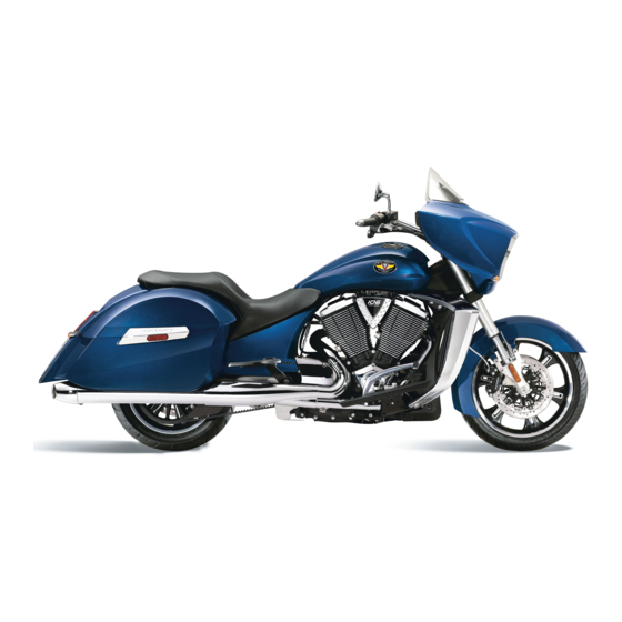
Any steering lock in cross roads bike


Need help?
Do you have a question about the Cross Roads Classic and is the answer not in the manual?
Questions and answers
Any steering lock in cross roads bike