GRAPHTEC midi LOGGER GL240 User Manual
Hide thumbs
Also See for midi LOGGER GL240:
- Q&a (38 pages) ,
- Quick start manual (24 pages) ,
- Setup manual (16 pages)
Table of Contents
Advertisement
Quick Links
Advertisement
Table of Contents

Related Manuals for GRAPHTEC midi LOGGER GL240


Summary of Contents for GRAPHTEC midi LOGGER GL240
- Page 1 GL240 USER’S MANUAL MANUAL NO.GL240-UM-153...
-
Page 3: To Ensure Safe And Correct Use
To Ensure Safe and Correct Use To Ensure Safe and Correct Use • To ensure safe and correct use of the GL240, read this manual thoroughly before use. • After having read this manual, keep it in a handy location for quick reference as needed. •... -
Page 4: Safety Precautions
. When using the GL240 in an environment where After checking that smoke is no longer being generated, grounding is not contact your sales representative or nearest Graphtec possible, ensure measured is no greater than 50 V (DC or vendor to request repair. - Page 5 Such action may cause the GL240 to break down. • Such action may impair the GL240’s performance. • Clean off any soiled areas using a soft dry cloth. Use prohibited Use prohibited Be sure to use the Graphtec-supplied AC adapter. • It will damage this device. Use prohibited...
- Page 6 Safety Precautions Safety Precautions CAUTION Do not touch the input terminals after the signal Confirm the power of supplier of signal is turned cable is connected to the measuring objects that are off before connecting the input cables to the input containing the voltage.
- Page 7 Safety Precautions Safety Precautions CAUTION When using the wireless LAN unit (optional), please When using the wireless LAN unit (optional) in a note the following: medical establishment, please note the following • rules: If you have an implantable pacemaker or implantable •...
-
Page 9: Introduction
Introduction Introduction Thank you for purchasing the GL240 midi LOGGER. Please read this manual thoroughly before attempting to use your new product to ensure that you use it correctly and to its full potential. Notes on Use Be sure to read all of the following notes before attempting to use the GL240 midi LOGGER. 1. - Page 10 This transmitter must not be co-located or operated in conjunction with any other antenna or transmitter. 4. Notes for Safe Operation (1) Be sure to use the Graphtec-supplied AC adapter. In environments where there is a lot of noise or where the power supply is unstable, we recommend that you ground the GL240.
- Page 11 Introduction • Do not put the tip of thermocouples to the object which is containing the leaked high voltage of chassis or metal etc. when the tip of thermocouples is not insulated. The leaked high voltage of object will cause damage to this device. •...
-
Page 12: Notes On The Use Of This Manual
(1) All rights reserved. No part of this publication may be reproduced, stored in a retrieval system, or transmitted, in any form or by any means, without the prior written permission of Graphtec Corporation. (2) The specifications and other information in this manual are subject to change without notice. -
Page 13: Table Of Contents
CONTENTS CONTENTS To Ensure Safe and Correct Use ..........Safety Precautions . - Page 14 CONTENTS CHAPTER 3 Settings and Measurement Window names and functions ......... . .3-2 Key Operation .
-
Page 15: Chapter 1 General Description
CHAPTER 1 General Description CHAPTER 1 General Description This chapter provides a general description of the GL240 and its features. PRODUCT SUMMARY Overview Features Operating Environment Notes on Temperature Measurement Notes on Using the Monitor Changing the Display Language... -
Page 16: Overview
CHAPTER 1 General Description 1.1 Overview The GL240 with color monitor is a compact, lightweight data logger. The GL240 can save the high-capacity measurement data directly in the internal memory or SD memory card. In addition, the setting, measuring and data capturing can be performed in online by connecting to the computer with the USB cable. -
Page 17: Operating Environment
CHAPTER 1 General Description 1.3 Operating Environment This section explains the operating environment for the GL240. Ambient Operating Conditions (1) Ambient temperature and humidity (the GL240 must be operated within the following ranges.) • Temperature range: 0 to 45°C (0 to 40°C when a battery pack is mounted, 15 to 35°C when battery is being charged) •... -
Page 18: Configuration When In Use
CHAPTER 1 General Description Configuration When in Use Do not use the GL240 standing upright or at an angle. It must always be laid flat or inclined on the stands. <Usage Configuration> 90˚ Laid flat Inclined on the stands Opening the stands Do not block the air vent on the GL240, as this will cause malfunctioning. -
Page 19: Notes On Temperature Measurement
CHAPTER 1 General Description 1.4 Notes on Temperature Measurement Please observe the following precautions when performing temperature measurement. • Do not block the air vents. Always provide a space of at least 30 cm on all sides of the GL240. •... -
Page 21: Chapter 2 Checks And Preparation
CHAPTER 2 Checks and Preparation CHAPTER 2 Checks and Preparation This chapter explains how to check the main module's external casing and accessories, and how to prepare the main module for operation. PRODUCT SUMMARY Checking the Outer Casing Checking the Accessories Nomenclature and Functions Connecting the Power Cable and Turning on the Power... -
Page 22: Checking The Outer Casing
CHAPTER 2 Checks and Preparation 2.1 Checking the Outer Casing After unpacking, check the GL240's outer casing before use. In particular, please check for the following: • Surface scratches • Other flaws such as stains or dirt 2.2 Checking the Accessories After unpacking, check that the following standard accessories are included. -
Page 23: Nomenclature And Functions
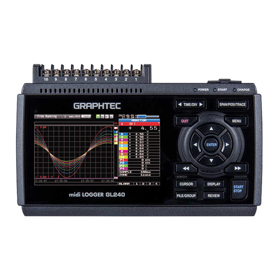
CHAPTER 2 Checks and Preparation 2.3 Nomenclature and Functions This section describes the names and function of parts of the GL240. Operation status LED AC adapter jack • POWER ON when the power is ON Blinking while accessing to the USB interface terminals memory •... -
Page 24: Connecting The Power Cable And Turning On The Power
CHAPTER 2 Checks and Preparation 2.4 Connecting the Power Cable and Turning on the Power This section describes how to connect the power cable and turn on the power. The connection method will vary depending on the type of power supply used. Connecting to an AC Power Supply Use the AC cable and AC adapter that are provided as accessories. - Page 25 CHAPTER 2 Checks and Preparation Connecting to a DC Power Supply Use the optional DC drive cable (B-514). • Use a power supply within the 8.5 to 26.4 VDC range. • For DC drive cable, please be sure to use the B-514. (1) Configure the tip of the DC drive cable (B-514: 2m) to enable it to be connected to the DC power supply.
-
Page 26: Connecting The Signal Input Cables
CHAPTER 2 Checks and Preparation 2.5 Connecting the Signal Input Cables This section describes how to connect the signal input cables. During wiring, confirm that the signal's supply source is turned OFF to prevent electrical shocks. Also, position the GL240 input cable away from any power lines and ground cables. Terminal Configuration and Signal Types Terminal assignment of standard terminal and Withstand high-voltage high-precision terminal is common. -
Page 27: Logic Alarm Cable Connection And Functions
CHAPTER 2 Checks and Preparation 2.6 Logic Alarm Cable Connection and Functions This section describes how to connect the logic alarm cables and the functions of cable. During wiring, confirm that the signal's supply source is turned OFF to prevent electrical shocks. Also, position the GL240 input cable away from any power lines and ground cables. - Page 28 CHAPTER 2 Checks and Preparation Internal equivalent circuit of I/O circuit • Alarm output Maximum ratings of the transistor for alarm output VCEO (Collector-emitter voltage) : 30 V IC (Collector current) : 0.5A +5 V PC (Collector dissipation) : 0.2W * The maximum ratings must not be exceeded.
- Page 29 CHAPTER 2 Checks and Preparation Wiring Cable tips are bare tips. Perform wiring for the necessary functions. Signal Name Channel Number Wire Color Logic/Pulse input Orange with red dotted line Orange with black dotted line Grey with red dotted line Grey with black dotted line Alarm output White with red dotted line...
-
Page 30: Mounting The Sd Memory Card
CHAPTER 2 Checks and Preparation 2.7 Mounting the SD Memory Card • When the SD memory card is inserted, make sure that the card is not locked. If locked, the data cannot be captured. • Please do not remove the SD memory card while accessing to the SD memory card (Device Access display is displayed in "red"... - Page 31 CHAPTER 2 Checks and Preparation How to remove the SD memory card (SD CARD2) (1) Make sure that the SD memory card displayed on the screen is green, and then remove it. POWER LED (2) Open the SD CARD2 protective cover. (3) The SD memory card is unlocked by pushing gently the SD memory card.
-
Page 32: Installing The Wireless Lan Unit (B-568: Option)
CHAPTER 2 Checks and Preparation 2.8 Installing the Wireless LAN Unit (B-568: Option) To connect the GL240 to the wireless LAN, insert the wireless LAN unit in the SD CARD2 slot. • When the SD memory card has been inserted into the SD CARD2 slot, please remove the SD memory card. •... - Page 33 CHAPTER 2 Checks and Preparation (4) Align the wireless LAN unit to the wireless LAN connection terminal and the fixed guide and then insert the wireless LAN unit until the unit is locked. Wireless LAN unit When the wireless LAN unit has been inserted, please be careful when handling so as not to hit and drop. Removing the wireless LAN unit Turn OFF the power and then remove the wireless LAN unit.
-
Page 34: Connecting To A Pc
CHAPTER 2 Checks and Preparation 2.9 Connecting to a PC Use the USB cable to connect the GL240 to a PC. Connection Using a USB Cable (1) This GL240 complies with the EMC Directive in the state when the supplied ferrite core is attached to the USB cable. - Page 35 CHAPTER 2 Checks and Preparation Connection through the wireless LAN (optional) Insert the wireless LAN unit (optional). For the insertion, refer to “2.8 Installing the Wireless LAN Unit (B-568: Option)”. 1. Access point (operating as a base unit): When connecting the GL240 to the GL100-WL (up to 1 units) or PC/Smartphone via the wireless LAN, the following devices and the operating environment are required.
-
Page 36: Using The Battery Pack (B-569 : Option)
CHAPTER 2 Checks and Preparation 2.10 Using the Battery Pack (B-569 : Option) • The B-569 (optional) is the only battery type that can be used with the GL240. • Refer to “4.3 Accessories/Optional Accessories” for information on the battery run time. •... - Page 37 CHAPTER 2 Checks and Preparation Charging the Battery Expected time required for charging: approx. 4.5 hours The battery pack is charged by mounting it in the GL240, attaching AC adapter to the GL240. (1) Mount the battery pack in the GL240 (see "Mounting the Battery Pack" in the previous page for the mounting procedure.).
-
Page 38: Connecting The Humidity Sensor (Optional)
CHAPTER 2 Checks and Preparation 2.11 Connecting the Humidity Sensor (Optional) Connect the + and - lead wires of the humidity sensor (the B-530: Option) to the desired terminals, and then insert the round connector into the 5V OUT connector on the GL240. Brown Humidity Sensor White... -
Page 39: Precautions To Observe When Performing Measurement
CHAPTER 2 Checks and Preparation 2.12 Precautions to Observe When Performing Measurement Please be sure to read the following carefully in order to prevent electric shocks or shorts. • Do not apply radio-frequency signals with high voltage (50 KHz or above). •... - Page 40 CHAPTER 2 Checks and Preparation • Input Circuit Diagram for Analog Input (Voltage, Thermocouples) 50Ω 500kΩ 0.05μF 0.05μF 500kΩ 50Ω Channel Switching Relay Capacitors have been incorporated into the input circuit to increase the noise elimination capability. After voltage measurement, when the inputs have been disconnected, there will still be some electric charge remaining.
-
Page 41: Noise Countermeasures
CHAPTER 2 Checks and Preparation 2.13 Noise Countermeasures • Be sure to connect the chassis GND of the measurement object. It may become effective by ensuring that the chassis GND wire of the measurement object is connected to a good ground. GL240 •... -
Page 42: Setting The Date And Time
CHAPTER 2 Checks and Preparation 2.14 Setting the Date and Time If you are using the GL240 for the first time, charge the internal rechargeable battery and then make the date and time settings. If the GL240 is not used for a period of approximately six months, the internal rechargeable battery may be discharged and the date and time may revert to the initial settings. -
Page 43: Chapter 3 Settings And Measurement
CHAPTER 3 Settings and Measurement CHAPTER 3 Settings and Measurement This chapter describes the setting and measurement procedures for the GL240. PRODUCT SUMMARY Window names and functions Key Operation Operation Modes Setting Menus WEB Server Function List of Error Codes... -
Page 44: Window Names And Functions
CHAPTER 3 Settings and Measurement 3.1 Window names and functions 4. Wireless sensor display 5. Device access display (Internal memory) 6. Device access display (SD memory card 2 / wireless LAN display) 1. Simplified message display 7. Remote lamp 2. Time/DIV display area 8. - Page 45 CHAPTER 3 Settings and Measurement 2. Time/DIV display area Displays the current time scale. 3. Status mark : Appears when neither capture nor replay is in progress. : Displayed when saving the captured data in the internal memory (SD1) or SD memory card (SD2).
- Page 46 CHAPTER 3 Settings and Measurement 6. Device access display (SD memory card 2 / wireless LAN display) : The SD memory card is not inserted into the SD CARD (SD2) slot. : The SD memory card is inserted into the SD CARD (SD2) slot, but it is not accessed. : The SD memory card in the SD CARD (SD2) slot is accessed.
- Page 47 CHAPTER 3 Settings and Measurement 10. AC/battery status indicator : Running on AC or DC power supply. : Running on the battery. The remaining battery power is 100 to 91%. : Running on the battery. The remaining battery power is 90 to 61%. : Running on the battery.
- Page 48 CHAPTER 3 Settings and Measurement 14. Pen display Displays the each channel signal position, trigger position, and alarm range. Trigger position Alarm range Rising Falling Win In Win Out Stop position Start position 15. Time stamp Displays the time stamp of a currently displayed waveform as time. This indicator shows that the measurement data was captured at 16:35:44.
- Page 49 CHAPTER 3 Settings and Measurement 18. Waveform display area Displays the waveform of the input signal. 19. Scale upper limit Displays the scale upper limit of the currently active channel. 20. Data capture bar (1) During data capture Displays the elapsed time and the internal memory and SD memory card usage status. Elapsed time Remaining time for data capture Amount of internal memory...
-
Page 50: Key Operation
CHAPTER 3 Settings and Measurement 3.2 Key Operation This section describes key operation. (2) TIME/DIV (1) SPAN/POSI/TRACE (3) MENU (4) QUIT (5) Direction Keys (6) ENTER (7) FAST FORWARD key (KEY LOCK) (11) CURSOR (8) START/STOP (USB DRIVE) (ALARM CLEAR) (12) FILE/GROUP (9) DISPLAY (10) REVIEW... - Page 51 CHAPTER 3 Settings and Measurement (2) TIME/DIV Press the left/right key of the [TIME/DIV] key to change the time axis display width. TIME/DIV display (3) MENU Open the settings window to capture data. For details on settings, refer to “3.4 Setting Menus”...
- Page 52 CHAPTER 3 Settings and Measurement (5) Direction Keys This key is primarily used for the following operations. • To move a menu or setting item during menu configuration. • To move the cursor during replay. • To move the active channel in the Waveform + Digital and Digital + Calculation Display screens ( keys).
- Page 53 CHAPTER 3 Settings and Measurement (8) START/STOP (USB Drive Mode) This key performs the following two operations: <Starts/stops capture> • During Free Running, starts capture. • During capture, stops capture. USB Drive Mode Operation Procedure In the “USB Drive Mode”, the internal memory (SD1) and SD memory card (SD2) can be check on a PC as an external storage device.
- Page 54 CHAPTER 3 Settings and Measurement (9) DISPLAY This key is used to switch the screen mode. You can switch the window mode during Free Running (when capturing is stopped) and Capturing. Pressing this key switches the screen display as follows: <Waveform + Digital Screen>...
- Page 55 CHAPTER 3 Settings and Measurement (10) REVIEW This key is used to replay captured data. • During Free Running, captured data is replayed. The screen used to specify the data replay source file appears; specify the file you want to replay. •...
- Page 56 CHAPTER 3 Settings and Measurement (11) CURSOR (ALARM CLEAR) • This key is used to switch between cursors A and B during replay. Pressing this key switches between cursor A and B. Refer to “(10) Data replay menu” in “3.4 Setting Menus” for details on cursor operation.
- Page 57 CHAPTER 3 Settings and Measurement Basic Procedures Used in Settings The following are basic operation procedures for settings. 1. Press the [MENU] key to open each menu. 2. Use the key to move the cursor to the items you want to set. 3.
-
Page 58: Operation Modes
CHAPTER 3 Settings and Measurement 3.3 Operation Modes You can check the system operation status in the status message display. < Free Running > < Capturing > <Replaying while capturing data> < Replaying > Operation Description Simple message display Free Running Startup status, or data is not being captured. - Page 59 CHAPTER 3 Settings and Measurement (1) Free Running The selected channel is enlarged. The display channel can be switched by operating the keys. The scale of the selected channel is indicated. The selected channel is displayed without coloration. In free-running, you primarily perform the settings for data capture. You can check the currently input signal in the waveform or digital value.
- Page 60 CHAPTER 3 Settings and Measurement (3) Data replaying during capture Displays the voltage at a point indicated by Cursor A or B or the selected cursor. Displays the measurement time at a point indicated by Cursor A or B or the selected cursor.
-
Page 61: Setting Menus
CHAPTER 3 Settings and Measurement 3.4 Setting Menus When you press the [MENU] key during Free Running, the following menu screens appear. <When optional wireless unit is installed> <When optional wireless unit is not installed> DATA TRIG OTHR (1) AMP settings This menu is used to specify input signal-related settings. - Page 62 CHAPTER 3 Settings and Measurement Setting Selections available Illumination / Range [Illuminance] / [Accumulated 2000, 20000lx, 200klx ultraviolet sensor illuminance] (GL100-WL+GS- [Ultraviolet] / [Accumulated 30mW/cm fixed LXUV) ultraviolet] Filter None CO2 sensor Range 5000ppm fixed (GL100-WL+GS- Filter None CO2) Adapter for AC Range AC clamp mode AC 1P2W, AC 1P3W, AC 3P3W...
- Page 63 CHAPTER 3 Settings and Measurement Setting Selections available Logic/Pulse Off, Logic, Pulse [Logic] Filter Off, On Misc. Waveform 0 to 31 for each of red, green, blue (RGB) color setting Trace Off, On setting [Pulse] Input Off, Revolution counts, Counts, Inst. Filter Off, On Slope...
- Page 64 CHAPTER 3 Settings and Measurement Switching displays Analog and logic/pulse can be switched as shown below. • Display Logic/Pulse Data • Display Analog Data Analog settings Specifies the conditions for analog signals. When you use CH ALL to set an input, range and filter, all channels are set to the same values if the input is the same.
- Page 65 CHAPTER 3 Settings and Measurement (1)-3 Range This is used to select the range of measurement. Input item Description 20, 50, 100, 200, 500 mV; 1, 2, 5, 10, 20, 50, 100V 1-5 V TEMP No selection (2000°C fixed) No selection (100% fixed) Available SPAN Settings <Voltage Ranges>...
- Page 66 CHAPTER 3 Settings and Measurement (1)-4 Filter Selects the range to be measured. Selection item Description No moving average is calculated. A moving average is calculated 2 times per sampling interval. A moving average is calculated 5 times per sampling interval. A moving average is calculated 10 times per sampling interval.
- Page 67 CHAPTER 3 Settings and Measurement (1)-5 EU (Scaling settings) This is used to convert the measured signals to other units. <For voltage input> <For temperature input> (2) (3) (2) (3) (4) (5) (6) Setting Description (1) EU Function Sets the scaling function to ON or OFF. (2) Meas.
- Page 68 CHAPTER 3 Settings and Measurement (1)-6 Misc. The information varies depending on GL240 amplifier and GS sensor or terminal/adapter (settable when it is connected through the wireless sensor). * Please check the setting target and the information of the item number in the table below. Setting object Setting Description...
- Page 69 CHAPTER 3 Settings and Measurement <Inter-CH Op Settings> (4) (5) (6) (7) (8) Setting Description (1) Inter-CH Op Settings Function Off, On If this setting is ON, the channel has a calculation mark in the digital display, etc. Calculation mark (2) Operation CH-X (Function) CH-Y CH-X...
- Page 70 CHAPTER 3 Settings and Measurement (1)-7 Logic/Pulse This is used to select the processing method for digital input. Selection item Description Digital input measurement is disabled. Logic Digital input is processed as logic signals. Pulse Digital input is processed as pulse signals. (1)-8 Input This is used to set the pulse measurement mode.
- Page 71 CHAPTER 3 Settings and Measurement (1)-11 EU (Scaling settings) This is used to convert the measured signals to other units. This setting is available only if Pulse is selected in (1)-7. (2) (3) (4) (5) (6) Setting Description (1) EU Function Sets the scaling function to ON or OFF.
- Page 72 CHAPTER 3 Settings and Measurement Wireless sensor (GL100-WL: optional) setting The GL240 can receive the optional wireless type (GL100-WL) and the data by installing the optional wireless LAN unit (B-568). For the wireless LAN setting method, refer to “(5) LAN setting” in “3.4 Setting Menus”. For the GS sensor and terminal/addapter connecting to the GL100-WL, refer to the GL100 User’s Manual.
- Page 73 CHAPTER 3 Settings and Measurement Temperature and humidity sensor of the wireless sensor setting: optional (GL100-WL+GS-TH) Perform the settings for the temperature and humidity sensor input of wireless sensors. When the wireless sensor and temperature and humidity sensors are connected, the setting screen is displayed.
- Page 74 CHAPTER 3 Settings and Measurement (1)-16 Other setting The following settings can be performed. Setting Description Annotation text string Set the annotation (comment) displayed in the CH. Program Inter-CH Set the contents of Program Inter-CH calculation calculation Four arithmetic operations (addition (+), subtraction (-), multiplication (x), division (÷)) can be used for the Program Inter-CH calculation Span setting Set the upper and lower limits of the span which the waveform is displayed.
- Page 75 CHAPTER 3 Settings and Measurement (1)-19 Range setting This is used to select the range to be measured. 1ch is used for temperature only, 2ch to 4ch are used for acceleration range. Setting Description 100°C fixed range 2ch to 4ch 2, 5, 10G;...
- Page 76 CHAPTER 3 Settings and Measurement 4ch Voltage / Temperature Terminal of the wireless sensor setting: optional (GL100-WL+GS-4VT) Perform the settings for the 4ch voltage / temperature terminal input of wireless sensors. When the wireless sensor and 4ch voltage / temperature terminal are connected, the setting screen is displayed.
- Page 77 CHAPTER 3 Settings and Measurement (1)-26 Other setting Annotation text, Inter-CH calculation, span, line width, trace, and zero point, etc. can be set. Refer to “(1)-6 Misc.” in “3.4 Setting Menus”. (1)-27 Logic / Pulse setting This is used to perform the setting related to the digital input to the GL240. Refer to “(1)-7 Logic/Pulse”...
- Page 78 CHAPTER 3 Settings and Measurement (1)-29 Sensor setting This is used to select the sensor type to be used. Setting Description TSR-A Set when the thermistor is GS-103AT-4P. TSR-J Set when the thermistor is GS-103JT-4P. (1)-30 Range setting The temperature range is fixed at 200°C. (1)-31 EU setting This is used to unit-convert the measurement signal.
- Page 79 CHAPTER 3 Settings and Measurement Illuminance / Ultraviolet Sensor of the wireless sensor setting: optional (GL100-WL+GS-LXUV) Perform the settings for the illumination / ultraviolet sensor input of wireless sensors. When the wireless sensor and illumination / ultraviolet sensor are connected, the setting screen is displayed. (1)-34 Input setting This is used to select the input conditions.
- Page 80 CHAPTER 3 Settings and Measurement (1)-36 EU setting The unit of Illumination/ultraviolet is converted. Refer to “(1)-5 EU (Scaling settings)” in “3.4 Setting Menus”. There is no “EU Function” for accumulated illuminance and accumulated ultraviolet. Even if the scaling setting is applied to the original measured value of CH, the accumulated illuminance is not reflected in the accumulated illuminance CH.
- Page 81 CHAPTER 3 Settings and Measurement CO2 sensor of the wireless sensor setting: optional (GL100-WL+GS-CO2) Perform the settings for the CO2 sensor input of wireless sensors. When the wireless sensor and CO2 sensor are connected, the setting screen is displayed. (1)-38 Input setting This is used to select the input conditions.
- Page 82 CHAPTER 3 Settings and Measurement (1)-41 Other settings The following settings can be performed. Setting Description Annotation text string Set the annotation (comment) displayed in the CH. Program Inter-CH Set the contents of Program Inter-CH calculation. calculation Four arithmetic operations (addition (+), subtraction (-), multiplication (x), division (÷)) can be used for the Program Inter-CH calculation.
- Page 83 CHAPTER 3 Settings and Measurement (1)-43 Range setting Select the range of the current (power) to measure. Setting Description Current 50, 100, 200A Power (20, 50, 100kW) It is linked to the current range. Do not change the range through the GL100-WL after setting the range of the GL240. The displayed values of the GL240 may not match the measured values.
- Page 84 CHAPTER 3 Settings and Measurement Branch adapter for GS of the wireless sensor setting: optional (GL100-WL+GS-DPA) When the wireless sensor and the branch adapter for GS are used, the composite measurements with combination of three ways can be performed. Combined GS sensor list Temperature and humidity sensor (GS-TH) Illumination / ultraviolet sensor (GS-LXUV) Temperature and humidity sensor (GS-TH)
-
Page 85: Data Settings
CHAPTER 3 Settings and Measurement (2) DATA settings This is used to specify capture-related items and calculations. Setting Selections available Sampling 10, 20, 50, 100, 125, 200, 250, 500ms, 1, 2, 5, 10, 20, 30s, 1, 2, 5, 10, 20, 30min, 1h;... - Page 86 (1) File Type Sets the file format used to save data. GBD : Creating a data file in Graphtec's proprietary binary format * It is not possible to change the data. CSV : Creating a data file in text format (2) Name Type Sets how a data file should be named.
- Page 87 CHAPTER 3 Settings and Measurement (2)-3 Ring capture setting • Ring Capture Function Setting Description (1) Ring Capture Set the capture function. Off: The capture function is disabled. Ring: Perform the ring recording. (For details, refer to the following figure.) Relay: The data is continuously saved in 2GB-separated files without missing data.
- Page 88 CHAPTER 3 Settings and Measurement • Relay Capture Function Without missing data, the data is continuously captured in 2GB-separated files. (Maximum capture capacity in one file is 2GB.) • When the CSV Format Recording and the backup function enabled, the relay recording is not able to perform. •...
- Page 89 CHAPTER 3 Settings and Measurement (2)-5 AC line filter This is used to enable or disable or disables the AC line filter while external sampling is enabled. Enable this setting to enable the digital filter. When you use external sampling and measure signals with high noise levels, set the AC line filter to ON.
- Page 90 CHAPTER 3 Settings and Measurement • If ring capture is On, the backup function is not available. • The memory that is the same as the capture destination cannot set as the backup save folder. • It takes a time for writing after recoding was stopped when many channels are recoding, when interval sampling is fast, when backup interval is long, because the backup data size becomes large.
-
Page 91: Trig Settings
CHAPTER 3 Settings and Measurement (3) TRIG settings This is used to specify trigger conditions and alarms. * When the GL100-WL+GS sensor is connected, the level alarm can be set as well. Setting Selections available Start Side Source Setting Off, Level, Alarm, External Input, Date, Weekly, Time [Level] Mode Analog: Off, H, L, Window In, Window Out... - Page 92 CHAPTER 3 Settings and Measurement (3)-1 Start side source setting This is used to specify trigger conditions to start data capture. Selection item Description Starts capturing data unconditionally when you press the [START/STOP] key. Level Starts capturing data when a specified level is reached. ->...
- Page 93 CHAPTER 3 Settings and Measurement (3)-3 Repeated capturing This is used to enable or disable the repeat function to conduct repeated capturing. Selection item Description The repeat function is disabled. The repeat function is enabled. After one capture is ended, the next capture is started (If the start side source setting is not Off, the GL240 waits for a trigger).
- Page 94 CHAPTER 3 Settings and Measurement Trigger level settings/Alarm level settings Specifies detailed conditions for each channel when the start and stop side source settings are Level. The configuration of the level trigger is as shown in the figure below. CH n Mode Level CH n...
- Page 95 CHAPTER 3 Settings and Measurement Level and Edge operations In the Level operation, a trigger is assumed to be generated if the trigger conditions are met when the [START] key is pressed. In the Edge operation, even if the trigger level achieves to the trigger generation level when the [START] key is pressed, it is not considered the trigger condition is satisfied if the level does not exceed the set level.
- Page 96 CHAPTER 3 Settings and Measurement Dead zones of trigger and alarm levels Trigger and alarm levels are provided with a dead zone in order to prevent false detection due to noise. The following figure shows the dead zone. <Mode: Rising> Trigger (alarm) point Trigger (alarm) level Dead zone level...
-
Page 97: Interface Settings
CHAPTER 3 Settings and Measurement (4) Interface settings This menu is used to specify conditions for PC connection. Setting Selections available Selections availableNew Line code CR+LF, LF, CR USB settings USB ID 0 to 9 (4)-1 New Line code Specifies the line feed code. Selection item Description CR+LF... -
Page 98: Lan Setting
CHAPTER 3 Settings and Measurement (5) LAN setting Perform the I/F wireless LAN unit setting and the wireless sensor registration. * When optional wireless LAN is not installed in the GL240, this screen is not displayed. <Station settings> <Access point settings> Setting Selections available Wireless LAN... - Page 99 CHAPTER 3 Settings and Measurement • Access point (operating as base unit) This is used to set when connecting between the GL240 and sold separately Petit LOGGER GL100-WL (1 unit) through the wireless LAN. • Station (operating as child unit) This is used to set the control from the PC and the data transfer to the PC when the sold separately wireless LAN base unit is connected.
- Page 100 CHAPTER 3 Settings and Measurement (5)-2 Station setting When connecting to the commercially available wireless LAN base unit and controlling multiple GL240s from PC, the e-mail send/receive function of the GL240 and Internet connection are available. (The following conditions is required to use them.) •...
- Page 101 CHAPTER 3 Settings and Measurement <Operation procedure> (1) Select the station, and then execute the wireless LAN restart. The “Wireless LAN restarting” is displayed and the restart is executed by the station setting. (2) Set the SSID. Enter in accordance with the procedure of "(9) Text input" described below. Also, to enter the SSID, follow the procedure in “(9) Text input”.
- Page 102 CHAPTER 3 Settings and Measurement (5)-4 Access point setting The connection between the GL240 and wireless sensor (GL100-WL) can be performed. The access point setting is a setting when the GL240 operates as a base unit. When selecting the wireless LAN as a station and then restarting the wireless LAN, the following screen is displayed.
- Page 103 CHAPTER 3 Settings and Measurement (5) Set the wireless standard 11n. When the IEEE802.11n is used, set to "ON". Select the "Reflection of setting" with the key when the above settings are finished. The "Wireless LAN restarting" message is displayed and the main unit is re-started to reflect the settings. (5)-5 Other setting Perform the wireless LAN setting in the other setting.
- Page 104 CHAPTER 3 Settings and Measurement Confirmation of setting completion Confirm on the AMP Setting screen that the wireless sensor is recognized. WL displayed group AMP Setting screen Channel group switching AMP Setting screen Run power cycle. Change the settings in the following two ways. •...
- Page 105 CHAPTER 3 Settings and Measurement (7) Then, set the [I/F] of the GL100-WL. • Wireless LAN mode: Station • DHCP: On • SSID: GTC_GL240_01 • Security: Off <Example of GL100-WL screen setting> [I/F] 6/10 WLAN Mode:Station▽ DHCP:On▽ TCP/IP:▽ SSID:GTC_GL240_01▽ Security:Off▽ Key:************▽ • Set the GL100-WL settings in reference to GL100-WL User’s Manual.
- Page 106 CHAPTER 3 Settings and Measurement After making sure that the device name is displayed, be sure to press the [OK] to reflect the settings. After the settings are completed, turn Off the GL100-WL’s and GL240’s powers and then start up the GL100-WL’s power.
- Page 107 CHAPTER 3 Settings and Measurement (5)-6 Server setting When the access point is set, set to AP-IP, and when the station is set, set to ST-IP. Setting Selections available FTP server setting FTP Client FTP Server Enter up to 127-character string User Name Enter up to 31-character string Password...
- Page 108 CHAPTER 3 Settings and Measurement FTP server setting This is used to perform the FTP server setting of backup destination. Selection item Description FTP Client FTP Server Enter the domain name or IP address of the FTP server. (Up to 127 characters) User Name Enter the user name of the FTP account.
- Page 109 CHAPTER 3 Settings and Measurement <Outgoing mail server settings> Selection item Description Outgoing mail server Sending (SMTP) server name Set the e-mail destination server name. (Up to 63 characters) settings SMTP port number Set the SMTP port number to from 0 to 65535. Time zone Set the time zone for the region to be used in the GL240.
-
Page 110: Other Settings
CHAPTER 3 Settings and Measurement (6) OTHER settings Various conditions can be set. Setting Selections available LCD brightness Bright, Middle, Dark Screen Saver Off, 10, 30 (sec.), 1, 2, 5, 10, 30, 60 (min.) Power On Start Disable, Enable TEMP. Settings Room Temp. - Page 111 CHAPTER 3 Settings and Measurement (6)-3 Power On Start Sets the feature which initiates measurement as soon as the GL240 isturned on. Selection item Description Disable When turning On the power, the capture is started automatically. Enable Even when turning On the power, the capture is not started automatically. When turned On the power, it may take some time until the wireless sensor is recognized.
- Page 112 CHAPTER 3 Settings and Measurement (6)-8 AC Line Frequency Select the frequency of the AC line used. Selection item Description 50Hz For an area with a power supply frequency of 50 Hz 60Hz For an area with a power supply frequency of 60Hz In this setting, select a frequency for noise removal using the digital filter.
- Page 113 CHAPTER 3 Settings and Measurement (3) Time Zone Sets the time zone of an area in which the GL240 is to be used. (Japan: +09:00) (4) Synchronized Time Sets the time at which the GL240 synchronizes to the time server. When the specified time comes, time synchronization operation is performed using a method specified in Synchronization Mode.
-
Page 114: File Menu
CHAPTER 3 Settings and Measurement (7) FILE menu The operations for file can be performed by pressing the [FILE/GROUP] key. The display items vary depending on the operation mode of free-running, replaying, and capturing. <Free Running Status> <Replay or Double-Screen Replay Status> <Capture Status>... - Page 115 Setting Description (1) File Type Sets the file format used to save data. GBD: Creating a data file in Graphtec's proprietary binary format. * Data tampering can be prevented. CSV: Creating a data file in text format. (2) Naming method Sets how a data file should be named.
- Page 116 CHAPTER 3 Settings and Measurement (7)-3 Remove / replace SD memory card The SD memory card (SD2) can be replaced during saving the data in the SD memory card. Perform the card replacement according to the following procedure. (1) Press the [FILE/GROUP] key to open the FILE menu. (2) Press the [ENTER] key in the “Remove/Switch SD card 2”.
- Page 117 CHAPTER 3 Settings and Measurement (7)-4 Specify Save Destination (Screen Copy) Saves the data that is replaying on the screen in the internal memory (SD1) or SD memory card (SD2) as an image file. <If the naming method is Auto> <If the naming method is Arbitrary>...
- Page 118 CHAPTER 3 Settings and Measurement (7)-7 Load Settings Loads and reflects the GL240 setting conditions from a file. Setting Description (1) Folder Specify a folder to which you want to save data. For details, refer to "(8) File box". (2) File Specify a file to which you want to save data.
-
Page 119: File Box
CHAPTER 3 Settings and Measurement (8) File box The file box used to set captured data files using the DATA menu or for disk operations accessed using the FILE menu is operated as follows. <File box by disk operations> Description Moves between folders. - Page 120 CHAPTER 3 Settings and Measurement <Example of operation procedure> The following shows an operation example where a folder named "TEST" is created for captured data and automatically saved. <Data capture setting menu> (1) Select the DATA menu. (2) Open the capturing setting menu by pressing the [ENTER] key on the “Capture destination file name” in the Capture setting.
-
Page 121: Text Input
CHAPTER 3 Settings and Measurement (9) Text input Related to text input operations such as annotation, EU (scaling) unit and captured data file name input. <New folder creation> Operation mode Description Operation method (1) Text input Upper case alphabet mode When the cursor key is moved to the uppermost part, operation can be selected using the left/right key ( Lower case alphabet mode... -
Page 122: Data Replay Menu
CHAPTER 3 Settings and Measurement (10) Data replay menu Select the data you want to replay from the “Data replay source” by pressing the [REVIEW] key and replay the captured data. <Select replay data source> Select items Description File Specify the file in the capture destination (save destination). Checksum verification Veifying checksum The checksum confirmation result is displayed in the dialog. - Page 123 CHAPTER 3 Settings and Measurement Setting Selections available Data search CH1 to 10, Logic, Pulse, Alarm * Logic and Pulse are displayed only if the Logic Pulse function is On in the AMP settings. [CH1 to CH10]•WL CH1-10 , WL1-8 [Logic] Logic1-8 [Pulse]...
- Page 124 CHAPTER 3 Settings and Measurement (10)-6 Date Search Sets the search conditions to be used in the next sections ((10)-7 "Find Next" and (10)-8 "Find Previous"). The operation is Edge operation. Selection item Description Sets the channel to be used for search. CH1-10, WL1-8 : The specified analog channel is used for search.
-
Page 125: Integrated Bar Graph Display
CHAPTER 3 Settings and Measurement (11) Integrated bar graph display By capturing the data after connecting to the GL100 that the integrated CH display possible GS sensor has been connected, the captured data can be displayed on the Integrated Bar Graph screen. Normally, the waveforms that has been piled up from the capture start are displayed in the Replay display. - Page 126 CHAPTER 3 Settings and Measurement Data detailed display area Page unit display Capture bar display Summation in page display Legend display Scale display Time in page display Selected integrated value display Maximum and minimum values display Setting items Description Page unit display The bar graph is displayed in page unit.
- Page 127 CHAPTER 3 Settings and Measurement Bar graph display area Bar graph scale Cursor display Setting items Description Bar graph display The integrated data is displayed in bar graph. The number of displayed bars depends on the page unit. Bar graph scale The scale of the time axis is displayed.
- Page 128 CHAPTER 3 Settings and Measurement (11)-3 Menu screen display Setting items Discription Page Display Date Select the page you want to display. Settable range is page unit. Settings Time When the page unit is “Week”, use the week number to search the week. Information Start point The start time and end time of captured data, and week number and day of...
-
Page 129: Quick Setting
CHAPTER 3 Settings and Measurement (12) Quick setting <Free Running> <Replay data> (11)-3 (11)-1 (11)-2 Screen Operation mode Sign Description Waveform Free Running SAMPLE Using the key, change the sampling interval. ZONE Using the key, change the zone division. Capturing ZONE Using the key, change the zone division. -
Page 130: To Cancel Key Lock By Password
CHAPTER 3 Settings and Measurement (13) To cancel key lock by password A password can be set to GL240 to cancel the key lock. (No password is set at factory default.) <Operation flow> 1. Set the password. Press the , , and ENTER keys at the same time to display the password setting screen shown below. Specify a 4 digit password. -
Page 131: Web Server Function
CHAPTER 3 Settings and Measurement 3.5 WEB Server Function Web browser allows operating and monitoring GL240 through an optional wireless LAN unit. • Supported Web browsers • Microsoft Internet Explorer 11 or later • Firefox 1.5 or later • Available functions using a Web browser •... - Page 132 Digital ........Displays the GL240 measured value digitally. Download of device file ....llows data captured with GL240 to be downloaded to your PC via FTP. Graphtec Web site ....Accesses to our Web site. Remote key operation KEY LOCK ......Sets and cancels key lock.
- Page 133 CHAPTER 3 Settings and Measurement Zoom DISPLAY ......Switches the display mode. Press this key to switch among Waveform + Digital, Expanded Waveform, and Digital screens. SPAN/POSITION/TRACE ..Switches the display in the digital display area. Press this key to switch among MONITOR, SPAN, POSITION, and TRACE.........
- Page 134 CHAPTER 3 Settings and Measurement Download of device file The captured data in the internal memory (SD1) or SD memory card (SD2) of the GL240 can be downloaded to the PC. To display the FTP site in the Explorer from the figure above, press the Alt key and click the "View" and then click the "Open FTP side with Explorer".
-
Page 135: List Of Error Codes
CHAPTER 3 Settings and Measurement 3.6 List of Error Codes If an error code is displayed on the GL240, please handle errors in reference to the table below. Error code Description Unexpected error Please contact us. File not found. The operation target is not a folder. Hardware error There is a possibility that the hardware has failed. -
Page 137: Chapter 4 Specification
CHAPTER 4 Specification CHAPTER 4 Specification This chapter describes the basic specifications for the GL240. PRODUCT SUMMARY Standard Specifications Function Specifications Accessories/Optional Accessories External Dimensions... -
Page 138: Standard Specifications
CHAPTER 4 Specification 4.1 Standard Specifications Standard Specifications Item Description Number of analog inputs 10 channels External input and output functions Trigger input or External sample pulse (1ch), Logic input (4ch) or Pulse input (4ch), Alarm output (4ch) Data backup functions Setup parameters: EEPROM/Clock: Lithium battery Clock accuracy ±0.002% (accurate within about 50 seconds per month) (23°C environment) -
Page 139: Memory Devices
CHAPTER 4 Specification Memory devices Item Description Memory capacity Internal memory (SD): approx. 4GB SD CARD2 slot: 1 (Compatible with SDHC, up to approx. 32GByte memory available) * Possible to save up to 2GByte for one file Memory contents • Setup conditions •... -
Page 140: Input Unit Specifications
CHAPTER 4 Specification Input Unit Specifications Item Description Number of input channels 10 channels Input terminal type M3 screw type terminals (Rectangular flat washer) Input method Photo MOS relay scanning system All channels isolated, balanced input Scan speed 10 ms/1 ch maximum Measurement ranges Voltage: 20, 50, 100, 200, 500 mV;... -
Page 141: Function Specifications
CHAPTER 4 Specification 4.2 Function Specifications Function Specifications Item Description Display screen Waveform + Digital screen, All Waveform screen, Digital + Calculation Display screen, Expanded digital screen, Integrated bar graph (when some GS sensor is connected) * Can be switched using the dedicated key (toggle operation) * For the Expanded Digital screen, the number of channels and the display channel must be specified Sampling interval... -
Page 142: Trigger/Alarm Functions
CHAPTER 4 Specification Trigger/Alarm Functions Item Description Repeat Trigger Off, On Trigger types Start: Data capture starts when a trigger is generated. Stop: Data capture stops when a trigger is generated. Trigger conditions Start: Off, Level, Alarm, External, Time, Date, Weekly Stop: Off, Level, Alarm, External, Time, Date, Weekly Trigger judgment modes Combination: Level OR, Level AND, Edge OR, Edge AND... -
Page 143: Accessories/Optional Accessories
CHAPTER 4 Specification 4.3 Accessories/Optional Accessories Control Software Item Description Compatible operating system Windows10/Windows8.1/Windows8/Windows7/Windows Vista Function Main unit control, realtime data capture, data conversion Number of groups 4 groups MAX Number of CHs per 1 group Up to number of connected module Maximum number of channels 1000 ch maximun Settings... -
Page 144: Battery Pack B-569 (Option)
CHAPTER 4 Specification Battery Pack B-569 (Option) Item Description Capacity 7.2V/2900mAh Battery type Lithium secondary battery Running time When using the LCD display: approx. 6 hours When using the screensaver: approx. 7 hours * 1-sec sampling, capturing to internal memory (SD1), new battery pack, and +25°C environment. -
Page 145: List Of Options
CHAPTER 4 Specification List of Options Item Model Description Input/output cable for GL B-513 2 m long (no clip on end of cable) DC drive cable B-514 2 m long (no clip on end of cable) Humidity sensor * B-530 3 m long (with power plug) M3 screws with flat washers (60) B-543... -
Page 146: External Dimensions
CHAPTER 4 Specification 4.4 External Dimensions (without attaching rubber protection cover) 2-M4 thread (L5*) * When rubber protection cover is attached, required screw length is 8 mm (L8). Unit: mm Dimension precision: Error ± 3 mm Terminals Unit: mm Dimension precision: Error ± 0.5 mm 7.62 4-10... -
Page 147: Index
INDEX INDEX Sign 3-axis Acceleration / Temperature Sensor ..3-32 Data capture bar ......4ch Thermistor Terminal . - Page 148 INDEX Ping format ....... . . 3-75 3-69 Power On Start ......3-37 Illuminance / Ultraviolet Sensor .
- Page 149 INDEX 3-31 Temperature and humidity sensor ....3-69 Temp. Unit ........Text input .
- Page 151 Specifications are subject to change without notice. GL240 User's Manual GL240-UM-153 December 20, 2018 2nd edition-01 GRAPHTEC CORPORATION...
Need help?
Do you have a question about the midi LOGGER GL240 and is the answer not in the manual?
Questions and answers