Table of Contents
Advertisement
Quick Links
- 1 Accessories and Options
- 2 Model Configuration
- 3 Configuration
- 4 How to Upgrade the Gl200/A Flash Rom from the Usb Memory Device
- 5 Entering the System Setup Menu
- 6 Performing Setup1 (Voltage Input)
- 7 Performing Setup2 (Room Temperature Compensation)
- 8 Inspection and Check Methods
- Download this manual
Advertisement
Table of Contents

Related Manuals for GRAPHTEC gl200


Summary of Contents for GRAPHTEC gl200
- Page 1 LOGGER 200/ 200A GL200-UM-251 SERVICE MANUAL GL200-UM-251-05-9370...
- Page 3 08.08.20 Information for the GL200A was added. 08.08.20 Part number for top covers were corrected. 08.08.20 Part number for bottom cases were corrected. 08.08.20 Part number for battery covers were corrected. 08.08.29 Note for the firmware version was corrected. GL200-UM-251-9370...
- Page 4 TO ENSURE SAFETY This Service Manual has been compiled for the purpose of facilitating repair and maintenance of the GL200 midi LOGGER by Graphtec service personnel and other persons who have undergone equivalent technical training. Maintenance or repair by unauthorized service personnel is to be strictly avoided. Because the GL200 contains numerous internal components with a high electric potential, such work by unauthorized service personnel could cause human injury or serious damage to the GL200 midi LOGGER.
-
Page 5: Table Of Contents
1.1 Model Configuration .....................1-1 1.2 Accessories and Options .....................1-1 2. UPGRADING THE FIRMWARE ............. 2-1 2.1 How to Upgrade the GL200/A Flash ROM from the USB memory device ....2-1 3. DISASSEMBLY AND REASSEMBLY ............ 3-1 3.1 Notes on Disassembly and Reassembly ..............3-1 3.2 Removing the Side Pads ....................3-1... -
Page 6: Configuration
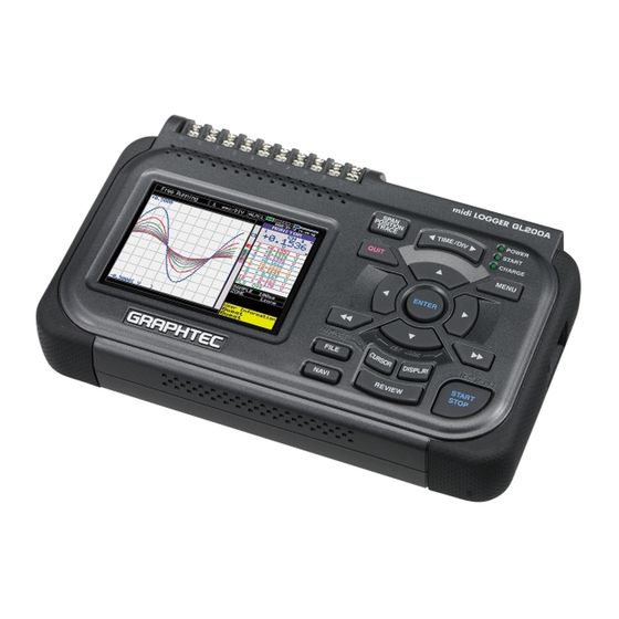
1. CONFIGURATION 1. CONFIGURATION 1.1 Model Configuration GL200 : 10-channel model with color monitor and internal memory 1.2 Accessories and Options GL200/GL200A Model Unit name Description name Humidity Sensor B-530 Same as GL450/500 Battery Pack B-517 Same as GL450/500 DC Drive Cable... - Page 7 1. CONFIGURATION GL200-UM-251-9370...
-
Page 8: Upgrading The Firmware
“Please Turn Off the Power. I have locked up.” (4) Turn off the power to the GL200/A when the above message is displayed or when the beeper sound stops. Delete the two main program files from the USB memory device. -
Page 9: Disassembly And Reassembly
(1) Peel off the left and right side pads from the main unit. Side Pad Main Unit Side Pad Re-assembly (1) Push the left and right side pads against the main unit and then install them on the main unit. GL200-UM-251-9370... -
Page 10: Disassembling The Top Cover And The Bottom Case Assembly
(3) Disconnect the connector between the main control board and the AMP board and then remove the top cover assembly. Top cover assembly Bottom case assembly M2L8 self-tapping screw Re-assembly (1) Re-assemble the top cover assembly and the bottom case assembly in the reverse order in which they were disassembled. GL200-UM-251-9370... -
Page 11: Replacing The Main Control Board
Lift up the black part of the connector using the small fl at-head screwdriver. Lift up this part Re-assembly (1) Re-assemble the main board in the reverse order in which it was disassembled. (2) Perform the Setup operations for the GL200/A when you replace the main control board. GL200-UM-251-9370... -
Page 12: Replacing The Control Panel Board
(4) Remove the four M2L5 self-tapping screws holding the control panel board from the top cover assembly. (5) Remove the control panel board from the top cover assembly. M2L5 self-tapping screw Control panel board Top cover assembly Re-assembly (1) Re-assemble the control panel board in the reverse order in which it was disassembled. GL200-UM-251-9370... -
Page 13: Replacing The Lcd
(4) Remove the M2L5 self-tapping screw holding the LCD bracket and the LCD from the top cover assembly. (5) Remove the LCD from the top cover assembly. M2L5 self-tapping screw LCD Bracket Top cover assembly Re-assembly (1) Re-assemble the LCD in the reverse order in which it was disassembled. GL200-UM-251-9370... -
Page 14: Replacing The Amp Board
(4) Remove the five M2L5 self-tapping screws holding the AMP board from the bottom case assembly. (5) Remove the AMP board and the input terminal board from the bottom case assembly. M2L5 self-tapping screw Input terminal board AMP board Bottom case assembly GL200-UM-251-9370... - Page 15 (6) Remove the input terminal board from the AMP board. Input terminal board AMP board Re-assembly (1) Re-assemble the AMP board in the reverse order in which it was disassembled. (2) Perform the Setup operations for the GL200/A when you replace the AMP board. GL200-UM-251-9370...
-
Page 16: Replacing The Input Terminal Board
(4) Remove the five M2L5 self-tapping screws holding the AMP board from the bottom case assembly. M2L5 self-tapping screw Input terminal board AMP board Bottom case assembly (5) Remove the AMP board and the input terminal board from the bottom case assembly. GL200-UM-251-9370... - Page 17 (6) Remove the input terminal board from the AMP board. Input terminal board AMP board Re-assembly (1) Re-assemble the input terminal board in the reverse order in which it was disassembled. (2) Perform the Setup operations for the GL200/A when you replace the input terminal board. GL200-UM-251-9370...
-
Page 18: Setup Procedures
4. SETUP PROCEDURES 4. SETUP PROCEDURES 4.1 Entering the System Setup Menu (1) Press the [MENU] key until the “OTHR” menu shown below appears. (2) Move the cursor to the “Information” position using the [Direction] keys. GL200-UM-251-9370... - Page 19 (6) Press the [ENTER] key to display the menu from which you can execute the various Setup operations. Setup mode Setup1 (Basic) Setup2 (Room temp.) (7) Select the Setup mode using the [Direction] keys, and then press the [ENTER] key. GL200-UM-251-9370...
- Page 20 4. SETUP PROCEDURES (8) Move the cursor to the “Execute Setup” position as shown below. (9) Press the [ENTER] key to start the selected Setup operation. GL200-UM-251-9370...
-
Page 21: Ac Line Cycle Setting
4. SETUP PROCEDURES 4.2 AC Line cycle Setting You must set the AC Line cycle setting of the GL200/A to the same cycle as that of your AC line before you perform the Setup1 and Setup2 operations. How to set the AC line cycle (1) Press the [MENU] key until the "OTHR"... -
Page 22: Performing Setup1 (Voltage Input)
• Have a voltage generator on hand that can output voltage up to 50 VDC (four-digit output). • Mutually connect the ground terminals of the voltage generator and the GL200/A. • Set the AC Line cycle setting of the GL200/A to the same cycle as that of your AC line. Wiring connection Voltage generator 0.00000 V... - Page 23 4. SETUP PROCEDURES Setup procedure (1) As shown in the figure above, connect the output of the voltage generator to the GL200/A’s CH1 input terminal. (2) Leave the GL200/A turned on for at least minutes. (3) After entering the System Setup mode, open the Setup menu as shown below.
- Page 24 (8) Press the [START] key and then wait until the "20 mV : [START]" message appears. Specify the voltage generator's output voltage setting to correspond to one of the displayed voltage ranges in the following table, and then input that voltage to the GL200/A. Message Input Voltage 0.000 mV 20 mV 20.000 mV...
-
Page 25: Performing Setup2 (Room Temperature Compensation)
• As shown below, use (T, ø0.32 mm) temperature compensation leads to connect the input terminals to the 0˚C reference temperature device (Zero controller). • Set the AC Line cycle setting of the GL200/A to the same cycle as that of your AC line. Wiring connection... - Page 26 "EEPROM : [ENTER]" message appears. (8) Press the [ENTER] key to begin writing the new Setup data to the EEPROM. (9) After the setup parameters have been registered to the EEPROM, the display closes and returns to normal mode. GL200-UM-251-9370...
- Page 27 :Setup2 (Room temp.) Area :Area2 :CH 2 (11) Repeat steps (4) to (8) for all the areas up to Area5. (12) Turn off the GL200/A. This completes the Room temp. setup. Setup flow for the Room temp. Procedure Selected area...
-
Page 28: Inspection And Check Procedures
(1) Press the [FILE] key, and then move the cursor to the “Load” position using the [Direction] keys. (2) Press the [ENTER] key to display the menu below. (3) Move the cursor to the “File Name” position using the [Direction] keys. GL200-UM-251-9370... - Page 29 (6) Press the [ENTER] key to display the menu shown below. (7) Specify the condition settings file to execute the various inspection operations. (8) Move the cursor to the “OK” position using the [Direction] keys. (9) Press the [ENTER] key to load the condition settings file. GL200-UM-251-9370...
-
Page 30: Measurement Accuracy
(1) Press the [MENU] key to display the menu shown below. (2) Move the cursor to the Range position of channel 1. (3) Press the [ENTER] key to display the menu shown below, and then select the reference voltage range. GL200-UM-251-9370... - Page 31 +20.0000V +19.984 V to +20.016 V 50 V +50.000 V +49.96 V to +50.04 V This value will change when the reference voltage is input from the voltage generator. (6) Press the [START/STOP] key when the input voltage stabilizes. GL200-UM-251-9370...
- Page 32 Confirm that this value is within the above ratings after data has been captured. The data with an automatically generated file name is captured to the memory. (8) Repeat steps (1) to (7), and then confirm that each value is within the above ratings. GL200-UM-251-9370...
-
Page 33: Temperature Accuracy
AC adapter Connect (K) compensation leads to the CH3, CH5, CH7 and CH9 input terminals. Note : The compensation leads should be connected individually. Do not connect in parallel. Connect the FG of the voltage generator and the AC adapter. GL200-UM-251-9370... - Page 34 (4) Input the reference voltage signal for the 0˚C reference temperature device (zero controller) according to the table below, then check that the level of measurement is within the rating. Input voltage precision ratings (Type K) Temperature Input voltage Standard 0 ˚C 0.000 mV -1.0 ˚C to +1.0 ˚C GL200-UM-251-9370...
-
Page 35: Parts Lists
6. PARTS LISTS 6.1 Recommended Parts List Part No. Part Name Description Q'ty Remarks 790420700 Main Control Board for GL200/A 790420701 AMP Board for GL200/A 790420702 Input Terminal Board for GL200/A 790420703 Control Panel Board for GL200/A Without AC Cable... -
Page 36: Parts Lists
6. PARTS LISTS 6.2 Parts Lists 6.2.1 Outer Casing Part No. Part Name Description Q'ty Remarks Rank 790420710 Top Cover Assy, GL200 790420753 Top Cover, GL200A 790420707 Bottom Case Assy, GL200 790420751 Bottom Case Assy, GL200A 604100043 Side Pad Outer Casing... -
Page 37: Bottom Parts
6. PARTS LISTS 6.2.2 Bottom Parts Part No. Part Name Description Q'ty Remarks Rank GL200/GL200A 790420701 AMP Board GL200/GL200A 790420702 Input Terminal Board GL200/GL200A 604100090 Covering Seal 790420709 Battery Cover Assy, GL200 790420752 Battery Cover Assy, GL200A Bottom Parts GL200-UM-251-9370... -
Page 38: Top Parts
6. PARTS LISTS 6.2.3 Top Parts Part No. Part Name Description Q'ty Remarks Rank GL200/GL200A 790420700 Main Control Board GL200/GL200A 790420703 Control Panel Board GL200/GL200A 604100053 Key Switch GL200/GL200A 562060005 LCD, COM35H3125XL GL200/GL200A 604100070 LCD Bracket GL200/GL200A 604100033 IO Panel... -
Page 39: Standard Accessories
6. PARTS LISTS 6.2.4 Standard Accessories Part No. Part Name Description Q'ty Remarks Rank 604109101 GL200-CDM01M CD Manual, Software 604109320 GL200A-CDM01M CD Manual, Software 604109140 GL200-UM-851 Quick Start Manual 604109390 GL200A-UM-851 Quick Start Manual 604109121 GL200-UM-901 Installation Manual Without AC Cable... -
Page 40: Block Diagram
7. BLOCK DIAGRAM 7. Block Diagram GL200-UM-251-9370...
Need help?
Do you have a question about the gl200 and is the answer not in the manual?
Questions and answers