GRAPHTEC midi LOGGER GL800 User Manual
Hide thumbs
Also See for midi LOGGER GL800:
- Quick start manual (24 pages) ,
- Quick start manual (22 pages)
Table of Contents
Advertisement
Advertisement
Table of Contents

Related Manuals for GRAPHTEC midi LOGGER GL800


Summary of Contents for GRAPHTEC midi LOGGER GL800
- Page 1 GL800 USER’S MANUAL MANUAL NO. GL800-UM-152...
-
Page 2: Introduction
3. Notes for Safe Operation (1) Be sure to use the Graphtec-supplied AC adapter. In environments where there is a lot of noise or where the power supply is unstable, we recommend that you ground the GL800. - Page 3 Introduction (5) Do not use the GL800 in the vicinity of other devices which are susceptible to electromagnetic interference. (6) Measured results may not conform to the stated specifications if the GL800 is used in an environment which is subject to strong electromagnetic interference. (7) Insofar as possible, position the GL800 input signal cables away from any other cables which are likely to be affected by electromagnetic interference.
-
Page 4: To Ensure Safe And Correct Use
To Ensure Safe and Correct Use To Ensure Safe and Correct Use • To ensure safe and correct use of the GL800, read this Manual thoroughly before use. • After having read this Manual, keep it in a handy location for quick reference as needed. •... -
Page 5: Safety Precautions
• Contact with a high-voltage component inside the GL800 may cause No disassembly electric shock. • If repair is required, contact your sales representative or nearest Graphtec vendor. Avoid using the GL800 in extremely dusty or humid places. • Such use may cause a fire hazard due to electrical shock or current leakage. - Page 6 Safety Precautions Safety Precautions WARNING Avoid using the GL800 in places where it may be exposed to water such as bathrooms, locations exposed to wind and rain, and so on. Avoid water Watch out for electrical shock Prevent dust or metallic matter from adhering to the power supply connector. •...
- Page 7 • Use in such status may cause a fire hazard due to electrical shock or current leakage. Unplug the power • Contact your sales representative or nearest Graphtec vendor to request cord from the socket repair. Do not input voltage that exceeds the permissible input voltage range that is specified on the GL800's label.
- Page 8 Safety Precautions Safety Precautions CAUTION Do not attempt to lubricate the GL800's mechanisms. • Such action may cause the GL800 to break down. No lubrication Never clean the GL800 using a volatile solvent (such as thinner or benzine). • Such action may impair the GL800's performance. •...
-
Page 9: Table Of Contents
Contents CONTENTS Introduction ................................ i To Ensure Safe and Correct Use ........................iii Conventions Used in This Manual ......................iii Description of Safety Symbols ....................... iii Safety Precautions ............................iv General Description ...................1-1 Overview ............................. 1-2 Features ............................1-2 Input ............................. 1-2 Display &... - Page 10 Contents 2.12 Mounting the Extension Terminal Base Set (B-537) ............. 2-17 B-537 Set Contents ........................2-17 To Mount ............................ 2-17 2.13 Mounting the 20 Channel Extension Terminal Set (B-538) ..........2-18 B-538 Set Contents ........................2-18 To Mount ............................ 2-18 2.14 Precautions to Observe When Performing Measurement ...........
- Page 11 Contents Accessory/Option Specifications .................... 4-7 Control Software .......................... 4-7 Accessories ..........................4-7 Battery Pack B-517 (Option) ......................4-7 Humidity Sensor B-530 (Option) ....................4-8 Options ............................4-8 External Dimensions ......................... 4-9 Index ......................I-1...
-
Page 12: General Description
CHAPTER General Description This chapter provides a general description of the GL800 and its features. Overview Features Operating Environment Notes on Temperature Measurement Notes on Using the Monitor Changing the Display Language... -
Page 13: Overview
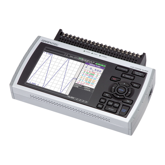
General Description 1.1 Overview The GL800 (with color monitor and internal memory) are compact, lightweight, multi-channel data loggers. GL800 are provided with 20 channels as a standard measurement feature, or can be extended up to 200 channels by attaching additional terminal sets. GL800 are also equipped with an internal flash memory to store data and enable the direct capture of a large volume of data to USB memory. -
Page 14: Operating Environment
General Description 1.3 Operating Environment This section explains the operating environment for the GL800. Ambient Operating Conditions (1) Ambient temperature and humidity (the GL800 must be operated within the following ranges.) • Temperature range: 0 to 45°C (15 to 40°C when battery pack is mounted) •... -
Page 15: Notes On Temperature Measurement
General Description 1.4 Notes on Temperature Measurement Please observe the following precautions when performing temperature measurement. (1) Do not block the air vents. Always provide a space of at least 30 cm on all sides of the GL800. (2) For stabilized temperature measurement, allow the GL800 to warm up for at least 30 minutes after turning it on. -
Page 16: Checks And Preparation
CHAPTER Checks and Preparation This chapter explains how to check the GL800's external casing and accessories, and how to prepare the GL800 for operation. Checking the Outer Casing Checking the Accessories GL800 Part Names and Functions Connecting the Power Cable and Turning on the Power Connecting the Signal Input Cables Logic Alarm Cable Connection and Functions Attaching USB Memory... -
Page 17: Checking The Outer Casing
Checks and Preparation 2.1 Checking the Outer Casing After unpacking, check the GL800's outer casing before use. In particular, please check for the following: • Surface scratches • Other flaws such as stains or dirt 2.2 Checking the Accessories After unpacking, check that the following standard accessories are included. Standard Accessories Item Remarks... -
Page 18: Gl800 Part Names And Functions
Checks and Preparation 2.3 GL800 Part Names and Functions This section describes the names and function of parts of the GL800. Power switch PC interface terminals Monitor Operation status LED ・ USB ・ POWER : ON when the power is ON ・... -
Page 19: Connecting The Power Cable And Turning On The Power
Checks and Preparation 2.4 Connecting the Power Cable and Turning on the Power This section describes how to connect the power cable and turn on the power. The connection method will vary depending on the type of power supply used. Connecting to an AC Power Supply Use the AC cable and AC adapter that are provided as accessories. -
Page 20: Connecting To A Dc Power Supply
Checks and Preparation Connecting to a DC Power Supply Use the optional DC drive cable (B-514). CAUTION Use a power supply within the 8.5 to 24 VDC range. (1) Configure the tip of the DC drive cable (B-514: 2m) to enable it to be connected to the DC power supply. -
Page 21: Connecting The Signal Input Cables
Checks and Preparation 2.5 Connecting the Signal Input Cables This section describes how to connect the signal input cables. Terminal Configuration and Signal Types CH20 + − Connection diagram Direct voltage input Thermocouple input + + Direct voltage − − Compensation copper wire Resistance temperature detector input... -
Page 22: Logic Alarm Cable Connection And Functions
Checks and Preparation 2.6 Logic Alarm Cable Connection and Functions The logic alarm cable (B-513) enables logic/pulse input, external trigger input, and alarm signal output. Connect the logic alarm cable (B-513) to the external input/output terminal as shown below. Logic alarm cable (B-513) Logic/Pulse Specifications Item Description... - Page 23 Checks and Preparation Wiring Cable tips are bare tips. Perform wiring for the necessary functions. Signal Name Channel Number Wire Color Logic/Pulse output Orange with red dotted line Orange with black dotted line Grey with red dotted line Grey with black dotted line Alarm output White with red dotted line White with black dotted line...
-
Page 24: Attaching Usb Memory
Checks and Preparation 2.7 Attaching USB Memory Attaching USB memory to the GL800 allows you store measured data directly. CAUTION Adequate precautions against static electricity must be taken when handling USB memory. Inserting a USB Memory Attach the USB memory to the USB memory terminal. USB Memory CAUTION When you attach the USB memory to GL800, be careful during handling so as not to bump or drop the unit. -
Page 25: Connecting To A Pc
Checks and Preparation 2.8 Connecting to a PC Use the USB, LAN Interface to connect the GL800 to a PC. Connection Using a USB Cable Use the USB cable to connect the GL800 to a PC. USB cable CHECKPOINT If the USB cable is used, the USB driver must be installed in your PC. Please refer to "Application Software Instruction Manual"... -
Page 26: Lan Connection
Checks and Preparation LAN Connection Use a LAN cable to connect the GL800 to a PC. LAN cable Cable Types • Use a crossing cable when connecting directly to a PC, without using a hub. LAN cable (crossing) • Use a straight cable when using a hub. LAN cable LAN cable (straight) -
Page 27: Using The Battery Pack (Option)
Checks and Preparation 2.9 Using the Battery Pack (Option) The B-517 battery is the only battery type that can be used with the GL800. Mounting the Battery Pack (1) While lightly pushing the grip of the battery cover, slid the cover in the direction indicated by the arrow. -
Page 28: Charging The Battery
Checks and Preparation Charging the Battery Expected time required for charging: • battery pack x 1: approx. 4 hours • battery pack x 2: approx. 8 hours The battery pack is charged by mounting it in the GL800, attaching AC adapter to the GL800. (1) Mount the battery pack in the GL800 (see the previous section for the mounting procedure). -
Page 29: Connecting The Humidity Sensor (Option)
Checks and Preparation 2.10 Connecting the Humidity Sensor (Option) Connect the + and - lead wires of the humidity sensor (the B-530 option) to the desired terminals, and then insert the round connector into the 5V OUT connector on the GL800. Connected to the 5V OUT terminal. -
Page 30: Mounting And Removing The Terminal Unit
Checks and Preparation 2.11 Mounting and Removing the Terminal Unit Remove and mount terminal units as shown below. CAUTION Make sure the GL800’s power is OFF when removing or mounting terminal units. To Remove Pull the terminal unit out towards the direction indicated by the arrow while pressing the two locks at the bottom of the unit. -
Page 31: To Mount
Checks and Preparation To Mount Insert the tabs at the top of the terminal unit into the slots of the GL800, and push in the unit until the lock tabs at the bottom of the unit are securely locked. (1) Insert tabs at the top of the terminal unit into the slots. (2) Press the unit in the direction shown until it is securely locked. -
Page 32: Mounting The Extension Terminal Base Set (B-537)
Checks and Preparation 2.12 Mounting the Extension Terminal Base Set (B-537) Mount the extension terminal base set as shown below. CAUTION Make sure the GL800’s power is OFF when mounting the extension terminals. B-537 Set Contents Extension Terminal Base Unit : 1 Extension Terminal Cable : 1 To Mount (1) Remove the terminal unit mounted to the GL800 (refer to 2-11). -
Page 33: Mounting The 20 Channel Extension Terminal Set (B-538)
Checks and Preparation 2.13 Mounting the 20 Channel Extension Terminal Set (B-538) Mount the 20 channel extension terminal set as shown below. CAUTION Make sure the GL800’s power is OFF when mounting the extension terminals. B-538 Set Contents Extension Terminal Base Unit : 1 20 Channel Terminals : 1 Connection Plate : 1 M4 x 6 Flat Head Screw : 4... - Page 34 Checks and Preparation (3) Connect the extension terminal cable to the extension terminal base unit. * Press in the cable until it is securely locked. Extension terminal cable (4) Connect the other end of the extension terminal cable to GL800. * Press in the cable until it is securely locked.
-
Page 35: Precautions To Observe When Performing Measurement
Checks and Preparation 2.14 Precautions to Observe When Performing Measurement Please be sure to read the following carefully in order to prevent electric shocks or shorts. DANGER • Do not apply voltage of AC30 Vrms or 60 VDC or above between the analog input section and main unit (GND terminal), or between each analog input channel. -
Page 36: Noise Countermeasures
Checks and Preparation 2.15 Noise Countermeasures Be sure to connect the chassis GND of the object to be measured. It may become effective by ensuring that the chassis GND wire of the measurement object is connected to a good ground. Measurement object GL800 Input terminals... -
Page 37: Setting The Date And Time
Checks and Preparation 2.16 Setting the Date and Time If you are using the GL800 for the first time, charge the internal rechargeable battery and then make the date and time settings. CAUTION If the GL800 is not used for a period of approximately six months, the internal rechargeable battery may be discharged and the date and time may revert to the initial settings. -
Page 38: Settings And Measurement
CHAPTER Settings and Measurement This chapter describes the setting and measurement procedures for the GL800. Window names and functions Key Operation Operation Modes Setting Menus WEB Server Function... -
Page 39: Window Names And Functions
Settings and Measurement 3.1 Window names and functions 3. Device access display 4. Key lock display 7. AC/battery status display 1. Simplified message display 5. Remote display 2. TIME/DIV 6. Clock display 17. Data capture bar 8. Waveform control display 16. - Page 40 Settings and Measurement 13. File name display : Displays the name of the file used to capture data. 14. Lower limit scale : Displays the lower limit scale of the currently active channel. 15. Waveform display : Displays the waveform of the input signal. 16.
-
Page 41: Key Operation
Settings and Measurement 3.2 Key Operation This section describes key operation. (1) CH GROUP (2) SPAN/TRACE/POSITION (3) TIME/DIV (5) QUIT (4) MENU (6) Direction Keys (7) ENTER (8) FAST FORWARD key (KEY LOCK) (9) START/STOP (USB DRIVE) (13) FILE (14) NAVI (12) CURSOR (ALARM CLEAR) (11) DISPLAY (10) REVIEW... -
Page 42: Span/Trace/Posion
Settings and Measurement (2) SPAN/TRACE/POSION Switches the display in the digital display. Used to change the settings related to waveform display during Free Running (when stopped), data capture and data replay. Pressing this key will switch displays as shown below. MONITOR SPAN POSITION... -
Page 43: Menu
Settings and Measurement (4) MENU Open the settings window to capture data. For details on settings, see "3.4 Setting Menus". (5) QUIT (LOCAL) This key is primarily used for the following operations. • To cancel a setting during menu configuration. •... -
Page 44: Enter
Settings and Measurement (7) ENTER This key is primarily used for the following operation: • To finalize setting items during menu configuration or open submenus. (8) FAST FORWARD key (KEY LOCK) This key is primarily used for the following operations. •... -
Page 45: Review
Settings and Measurement USB Drive Mode Operation Procedure 1. Use a USB cable to connect the GL800 and a PC. (When the USB driver has not been installed, install it as described in the software manual "Installing the USB Driver".) 2. -
Page 46: Display
Settings and Measurement (11) DISPLAY This key is used to switch the window mode. You can switch the window mode during Free Running (when stopped) and Capturing. Pressing this key switches the window display as follows: <Waveform + Digital Screen> Default <Expanded Waveform screen>... -
Page 47: Cursor (Alarm Clear)
Settings and Measurement (12) CURSOR (ALARM CLEAR) <When replaying captured data> This key is used to toggle between cursors A and B during replay. cursor A cursor B cursor B cursor A <When alarm generated> When the alarm setting is “Hold generated Alarm”, the maintained alarm is cleared. Alarm-generated channels Alarm output terminal status ・Black : Alarm is not issued... -
Page 48: Navi
Settings and Measurement (14) NAVI This key is used to display the key operation content during Free Running, capture or replay. During display of the NAVI screen, an explanation of how the key is used is displayed in the window. Basic Procedures Used in Settings The following are basic operation procedures for settings. -
Page 49: Operation Modes
Settings and Measurement 3.3 Operation Modes You can check the system operation status in the simplified message display. operation operation simplified message display Free Running Start up status or data is not being captured Free Running Capturing Data is being captured in the main memory Memory Recording or USB device. -
Page 50: Capturing
Settings and Measurement (2) Capturing Capture time Note: "+++++:++:++" is displayed when the capture time is long. Time of Capturing Capture file name During data capture, data is captured into the Internal memory or USB device. You cannot use the MENU key to change the setting. Operations available during capture SPAN/TRACE/POSITION The SPAN/TRACE/POSITION key is used to change settings. -
Page 51: Replaying
Settings and Measurement (4) Replaying Displays captured data. Available operation during replaying SPAN/TRACE/POSITION The SPAN/TRACE/POSITION key is used to change settings. Menu operations during data The MENU key is used to move the cursor, search data and replay set calculation. Moving cursors The CURSOR key is used to switch between cursors A and B. -
Page 52: Setting Menus
Settings and Measurement 3.4 Setting Menus When you press the MENU key during Free Running, the following menu screens appear. The menu screens are classified by the tab for each setting item. DATA TRIG USER OTHR (1) AMP settings This menu is used to specify input signal-related settings. Setting Selections available Input... - Page 53 Settings and Measurement Switching displays Analog and logic/pulse can be switched as shown below. ・Display Logic/Pulse Data ・Display Analog Data Analog settings When you use CH ALL to set an input range and filter, all channels are set to the same settings if the input is the same.
- Page 54 Settings and Measurement <Temperature Ranges> Range Maximum SPAN Minimum SPAN (p-p) Measurement Range Minimum Resolution °C °C °C -270 to +2000 -200 to +1370 °C °C °C -270 to +2000 -200 to +1100 °C °C °C -270 to +2000 -200 to +400 °C °C °C...
- Page 55 Settings and Measurement (b) EU Value Specifies output after conversion. Set two points, the Upper and Lower parameters. (c) Dec pt This parameter specifies the decimal point position of the numeral to be specified as the EU value(s). (d) Unit Selects the converted unit, which can be specified as a user- defined character string consisting of alphanumerics.
- Page 56 Settings and Measurement Logic and Pulse settings Logic/Pulse Switching ..Switches the digital input. • Off: Digital input is disabled. • Logic: Digital input is processed as logic signals. • Pulse: Digital input is processed as pulse signals. Filter....... Sets the filter for digital input. •...
- Page 57 Settings and Measurement DATA settings This menu is used to specify capture-related items and calculations. DATA Menu Structure Setting Selections available Record Settings 100, 200, 500ms 1, 2, 5, 10, 20, 30s • Sampling Interval 1, 2, 5, 10, 20, 30min, 1h File Name •...
- Page 58 Settings and Measurement Name Type ......Set how the file is named. • Auto: Automatically uses the capture start time as the file name. Example: 20050101-123456_UG.GBD • Number part: Created on January 1, 2005, 12: 34:56. • UG part: Number of user capturing data UG: Guest U1: User 1 U2: User 2...
- Page 59 Settings and Measurement Start side source settings ... Specifies conditions to start data capture. • Off: Starts capturing data unconditionally. • Level: Starts capturing data when a specified level is reached. • Alarm: Starts capturing data when the alarm with the specified number is generated.
- Page 60 Settings and Measurement Trigger level settings/Alarm level settings Mode ........Specifies mode trigger/alarm output conditions. Off: Does not enable trigger/alarm. H: A trigger/alarm is generated when the signal input rises to (or exceeds) the specified level. Measurement starts (alarm generated) CH.1 L: A trigger/alarm is generated when the signal input falls to (or falls below) the specified level.
- Page 61 Settings and Measurement Lower - Level - Upper ..Specifies the trigger/alarm level(s) for the conditions set in Mode. • H, L: Input a numeric value. • Win In, Win Out: Input a numeric value for the upper and lower limit. Combination (for trigger only)..Sets the combination of trigger conditions set for each channel.
- Page 62 Settings and Measurement • Win In, Win Out: Input numeric values for the upper and lower levels. Logic Sets the trigger/alarm conditions for logic input. These conditions can be set when they have been enabled in the AMP settings. • Off: No trigger/alarm conditions set. •...
- Page 63 Settings and Measurement • Setting condition switch: Switches between Guest, User 1 and User 2. Since setting conditions are stored for each user, they can be called up easily by simply switching the user. • Macro file name: Specify the macro file name to be executed. •...
- Page 64 Settings and Measurement Interface settings This menu is used to specify conditions for PC connection. Settings Selections available New Line code CR+LF, LF, CR USB ID 0 to 9 IP address Numerical value Subnet mask Numerical value Port number Numerical value Gateway Numerical value New Line code ....
- Page 65 Settings and Measurement OTHR settings Other miscellaneous settings are made here. Setting Selections available LCD brightness Light, Medium, Dark Screen Saver Off, 10, 30 (sec.), 1, 2, 5, 10, 30, 60 (min.) Power On Start Disable, Enable Room Temp. Internal, External °C, °F Temp.
- Page 66 Settings and Measurement Burn Out ......Sets a feature which checks sensor burnout in a thermocouple. • Off: Disables burnout check. • On: Enables periodic burnout check. CAUTION During a burnout check, voltage is applied to the GL800. Therefore, set Burn Out to "Off" when GL800 is connected in parallel with other devices to avoid any effect from these voltages.
- Page 67 Settings and Measurement • File Operation Operate files in the main memory and USB device. For details on file operation, see on page 3-31. • BMP Save Saves a copy of the screen as a BMP file. Folder/File: Specify a folder when the Name Type is set to Auto. Specify a file name when the Name Type is set to User.
- Page 68 Settings and Measurement • Save current settings/Load settings Saves or loads main unit condition settings. Folder/File: Specify a folder when Name Type is set to Auto. Specify the file name when the Name Type is set to User. Name Type: Specifies how to name a file. •...
- Page 69 Settings and Measurement <Setting example> The following shows an operation example where a folder named "TEST" is created for captured data and automatically saved. In the [Data save Destination], choose [Select folder] and press the ENTER key. Use the key to move to the target folder. Use the key to select [Create new folder].
- Page 70 Settings and Measurement Use the key to choose [Select file/folder]. Use the key to move the cursor to the created "TEST" folder, and press the ENTER key. Select [OK] to close the screen. Text input Related to text input operations such as annotation, EU (scaling) unit and captured data file name input.
- Page 71 Settings and Measurement • Operation Operation mode Description Operation method Text input Upper case alphabet mode When the cursor key is moved to the uppermost part, Lower case alphabet mode operation can be selected using the left/right key. After Numeric mode selecting an operation, use the down key to move the Symbol mode cursor to the desired character.
- Page 72 Settings and Measurement Cursor Position ....There are other functions for Cursor Move apart from the Level search function. Move to First Data: Moves the cursor to the start of the data. Move to Last Data: Moves the cursor to the end of the data. Move to Center: Moves the cursor to the center of the data.
- Page 73 Settings and Measurement Statistical calculation between cursors : Statistical calculation is performed on the data between the cursors. Function: There are five types of between-cursor calculation functions and one of these can be selected. (For details of each function, see on page 3-20.) Calculation results are displayed for 10 channels each and may be switched to display another group of 10 channels.
- Page 74 Settings and Measurement Operation mode Content Explanation Free Running SAMPLE Left/right key can be used to change the sampling interval. ZONE Left/right key can be used to change the zone division. Recording ZONE Left/right key can be used to change the zone division. Replaying SEARCH Left/right key can be used to perform search.
-
Page 75: Web Server Function
Settings and Measurement 3.5 WEB Server Function This function allows operating and monitoring GL800 via a Web browser. • Supported Web browsers • Microsoft Internet Explorer 6.0 or later • Netscape 6.2 or later • Firefox 1.5 or later • Opera 9.0 or later •... - Page 76 Download of device file ..Allows data captured with GL800 to be downloaded to your PC via FTP. Graphtec Web site ....Accesses to our Web site. • Remote key operation To operate GL800 from a remote location, click the corresponding GL800’s panel keys on the screen.
- Page 77 Settings and Measurement • Zoom CH GROUP ......Digital values for 10 channels are displayed on a single screen. Press this key to display the next group consisting of 10 channels. DISPLAY ......Switches the display mode. Press this key to switch among Waveform + Digital, Expanded Waveform, and Digital screens.
- Page 78 Settings and Measurement • Download of device file Allows memory data from GL800 and data in USB memory to be downloaded to your PC. <About the FTP server function> When an Internet Explorer FTP connection is used, login is automatically performed using an anonymous account and the files become read-only files.
-
Page 79: Specifications
CHAPTER Specifications This chapter describes the basic specifications for the GL800. Standard Specifications Function Specifications Accessory/Option Specifications External Dimensions... -
Page 80: Standard Specifications
Specifications 4.1 Standard Specifications Standard Specifications Item Description Number of analog input 1 unit (20 channels) or extension unit (maximum 200 channels) External input/output Trigger input, Logic input 4 channels or Pulse input 4 channels, Alarm output PC interface Ethernet (10BASE-T/100BASE-TX), USB (HighSpeed supported) provided as standard features Internal memory devices Internal memory: approx. -
Page 81: Internal Memory Devices
Specifications Internal memory devices Item Description Memory capacity Internal memory : approx. 12 MB Flash Memory USB memory : Max 2 GB (depends on the type of USB memory used) Memory contents • Setup conditions • Measured data • Screen copy PC Interface Item Description... -
Page 82: Input Unit Specifications
Specifications Input Unit Specifications Item Description Number of input channels 20 channels (maximum 200 channels with extension unit) Input terminal type M3 screw type terminals Input method Photo MOS relay scanning system All channels isolated, balanced input Scan speed 0.1s/10 ch maximum Measurement ranges Voltage: 20, 50, 100, 200, 500 mV;... -
Page 83: Function Specifications
Specifications 4.2 Function Specifications Function Specifications Item Description Display screen Waveform screen + Digital screen, Expanded Waveform screen, Digital screen + Calculation Display screen Note: Can be key-toggled Sampling interval 100 ms/10 ch maximum 100, 200, 500 ms; 1, 2, 5, 10, 20, 30 s; 1, 2, 5, 10, 20, 30 min; 1 h EU (scaling function) 4 points can be set for each channel Review function... -
Page 84: External Input/Output Functions
Specifications External Input/Output Functions Item Description Input/output types • Trigger input (1 ch) • Logic input (4 ch) or Pulse input (4 ch) • Alarm output (4 ch) *Switch between Logic and Pulse Input specifications Maximum input voltage: 0 to +24 V (single-ended ground input) Input threshold voltage: Approx. -
Page 85: Accessory/Option Specifications
Specifications 4.3 Accessory/Option Specifications Control Software Item Description Compatible operating system Windows 2000/XP Functions Main unit control, realtime data capture, data conversion Main unit settings Input settings, memory settings, alarm settings, trigger settings Allowed connection up to 10 Number of channels per 200 ch maximun connection Maximum number of channels 500 ch maximun... -
Page 86: Humidity Sensor B-530 (Option)
Specifications Humidity Sensor B-530 (Option) Item Description Allowable temperature range -25 to +80°C Allowable humidity range 0 to 100% RH ±3% RH (5 to 98% RH at 25°C) Relative humidity measurement accuracy Response time 15 s (90% response when membrane filter installed) Sensor output 0 to 1 VDC Sensor power source... -
Page 87: External Dimensions
Specifications 4.4 External Dimensions ± Dimensional precision: 5 mm Unit: mm... - Page 88 Index Index Date/Time ..........3-28, 3-29 Adapter ............2-2 Drive cable ............ 2-2 Cable ............. 2-2 Power Supply, Connecting ......2-5 Power Supply, Connecting ......2-4 Demo Waveform Mode ......3-28, 3-29 AC Line Frequency .......... 3-28 Department name ..........3-25 AC/battery status indicator .........
- Page 89 Index Repeated capturing .......... 3-22 KEY LOCK ............3-7 Replaying ............3-14 Key lock lamp ............. 3-2 Return to default settings ....... 3-28, 3-29 REVIEW key ............3-8 Room Temp. Compensation ......3-28 Language ..........3-28, 3-29 LCD brightness ..........3-28 LOCAL ...............
-
Page 90: Index
Index Waveform control display area ......3-2 Waveform display area ........3-3... - Page 91 Index...
- Page 92 The specifications, etc., in this manual are subject to change without notice. GL800-UM-152 Apr 1, 2007 2nd edition-01 GRAPHTEC CORPORATION...
- Page 93 503-10 Shinano-cho, Totsuka-ku, Yokohama 244-8503, Japan Tel : +81 (045) 825-6250 Fax : +81 (045) 825-6396 Email : info@graphteccorp.com Web : www.graphteccorp.com Printed in Japan...
Need help?
Do you have a question about the midi LOGGER GL800 and is the answer not in the manual?
Questions and answers