Table of Contents
Advertisement
Quick Links
Download this manual
See also:
User Manual
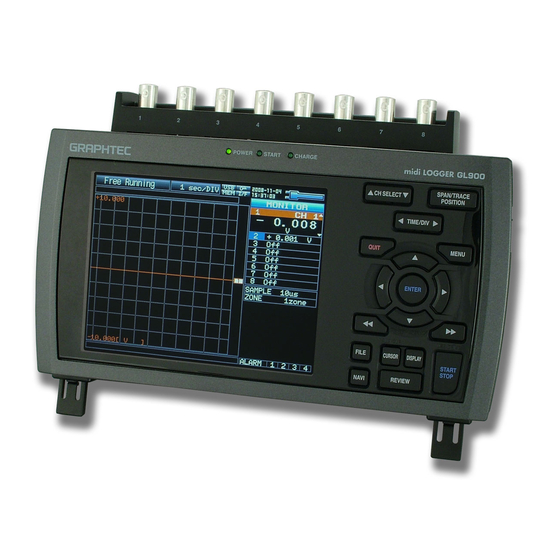
midi LOGGER
GL900
Thank you for purchasing the midi LOGGER GL900.
This Quick Start Guide describes the basic operations.
Please refer to the manual (PDF) in the CD-ROM for more information.
Checking the Outer Casing
After unpacking, check the GL900's outer casing before use to make sure that there
are no surface scratches or other flaws such as stains or dirt.
Checking the Accessories
o Quick Start Guide
o CD-ROM
Quick Start Guide
: 1
o AC cable/AC adapter : 1
: 1
GL900-UM-851
Don't forget to
check the setting
Advertisement
Table of Contents

Related Manuals for GRAPHTEC GL900


Summary of Contents for GRAPHTEC GL900
- Page 1 Please refer to the manual (PDF) in the CD-ROM for more information. Checking the Outer Casing After unpacking, check the GL900's outer casing before use to make sure that there are no surface scratches or other flaws such as stains or dirt.
-
Page 2: Table Of Contents
GL900 Contents Part Names ..................2 Connection Procedures ................ 3 Precautions to Observe When Performing Measurement ....4 Descriptions of the Control Panel Keys ..........5 Descriptions of the Menu Screens ............8 Measurement Procedure ..............9 ..9 1. Preparations : How to Make the Preparations Required for Data Capture .......... -
Page 3: Part Names
GL900 Part Names Top Panel Operation status LED Analog signal input terminals †POWER †START †CHARGE Power jack for the humidity sensor Humidity sensor (When using the B-530 option) USB memory terminal USB interface terminal Control panel keys LAN interface terminal... -
Page 4: Connection Procedures
Use a flathead screwdriver to push the button above the indicated as "DC LINE" on the GL900. ground terminal while connecting the grounding cable to the GL900. Connect the other end of the cable to ground. Making Connections to the Analog Input Terminals Direct voltage input... -
Page 5: Precautions To Observe When Performing Measurement
It may cause damage to the measurement device. Warming-up The GL900 should be allowed to warm up with the power turned on for approximately 30 minutes to achieve operation according to the specified performance. Unused channels The analog input section has high impedance. -
Page 6: Descriptions Of The Control Panel Keys
POSITION to On or Off). TRACE Note: If the QUIT key is pressed when the GL900 is in the SPAN, POSITION, or TRACE mode, the display returns to MONITOR mode. . TIME/DIV Press the TIME/DIV key to change the time axis display range on the waveform screen. - Page 7 . MENU Press the MENU key to open a setup menu. Each time this key is pressed, the setup screen tabs change in the sequence shown below. lAMP Settings Used to make the input, range, filter and other settings. lData Capture Settings Used to make settings such as the sampling interval, data capture destination, and calculations during data capture.
- Page 8 Press the START/STOP key to perform a data capture start operation while the GL900 is in the Free Running status, and a data capture stop operation when data capture has ended. If this key is held down while the power to the GL900 is turned on, the GL900 goes into USB Drive Mode.
-
Page 9: Descriptions Of The Menu Screens
3.Device access lamp : Turns red when USB memory is accessed. When the GL900's internal memory is being accessed, the MEM lamp turns red. 4.Key lock lamp : Displays the key lock status. (Yellow = keys locked, white = not locked) 5.Remote lamp... -
Page 10: Measurement Procedure
GL900 Measurement Procedure In this section we will provide a simple explanation of the data capture procedure: Preparations Setup Data Capture Data Replay. Voltage measurement is performed here. Purpose of data capture : To measure the temperature of the target objects... -
Page 11: Setup: How To Make The Settings
2. Setup: How to Make the Settings Make the settings required for data capture. Here we will make only those settings that are absolutely necessary. The other settings will be left as the default settings (the settings made prior to shipment from the factory) Basic Setup Menu Operation The keys used on the menu screens are the keys, the ENTER key, and the QUIT... - Page 12 4. Press the MENU key and open the "DATA" menu. 5. Set the sampling interval to "10ms". Move the cursor to "Sampling" and then select "10ms". 6. Set the Data Capture Destination to "Internal RAM". Move the cursor to "Data Capture Destination" and then select "Internal RAM". Points to Internal RAM, Internal flash memory and USB memory can be selected for Remember !
- Page 13 (1) Move the cursor to "Data Capture File Name" and then press the ENTER key to show the submenu. (2) Move the cursor to "Folder" and the press the ENTER key to show the file menu. (3) Press the key to move to the "Internal Flash Memory" layer, press the key to align the cursor with the icon, and then press the ENTER key to show the file name input menu.
-
Page 14: Data Capture: How To Capture Data
Press the START/STOP key to end the data capture operation. (1) Press the START/STOP key. (2) A confirmation message is displayed. Press the ENTER key. (3) Data capture ends, and the GL900 goes into the Free Running status. This completes the data capture operation. -
Page 15: Data Replay : How To Replay Captured Data
Replay". Files that were captured in the past can also be replayed from the same menu. This completes our simple explanation of how to use the basic GL900 functions. The GL900 has many other convenient functions. Please see the next five pages for further details. -
Page 16: Convenient Functions
GL900 Convenient Functions The GL900 is provided with various functions that enable it to be used more effectively. We have selected three of those functions to describe in further detail. Timer Functions and Trigger Functions to Control Data Capture Start/Stop Operations Timer functions and trigger functions can be used to control the timing of the start of a data operation, and the timing of the end of a data capture operation. - Page 17 Trigger Functions Specify the condition as "Start data capture when the CH1 level exceeds 0.3V". (1) Press the MENU key to open the "TRIG" menu and then set the Start Source setting to "Level". (2) Set the Combination to "Edge OR". Points to Level detects whether or not it is Remember !
-
Page 18: Span, Position And Trace Functions To Adjust The Waveform Display
The span, position and trace operations can be performed while the Remember ! GL900 is in the Free Running status, while it capturing data, and while it is replaying data. The changes made are applied to the displayed data only, and so the original data is not affected in any way. -
Page 19: Specifications
GL900 Specifications Standard Specifications Item Description Number of analog terminal 8 channels units External input and output Trigger input (1ch), Logic input (4ch) or Pulse input (4ch), Alarm output (4ch) functions Ethernet (10BASE-T/100BASE-TX), USB (HighSpeed supported) provided as standard features... -
Page 20: Input Unit Specifications
Input Unit Specifications Item Description Number of input channels 8 channels (fixed) Voltage BNC connectors Input terminal type M3 screw type terminal board Temperature All channels isolated Imbalanced input Input method Simultaneous sampling of all channels 10 s Maximum sampling speed 20m 50m 100m 200m 500m Voltage 1 2 5 10 20 50 100 200 500V 1-5V F.S. -
Page 21: Installation Guide
Insert the accompanying midi LOGGER GL900 CD-ROM in the PC's CD drive. Connecting the PC and GL900. Connect the PC and GL900 via a USB cable and power on the GL900. Installing the USB driver The "Found New Hardware" message appears, followed by the Install New Hardware wizard for the environment settings tool. - Page 22 June 1, 2008 GL900 Quick Start Guide 1st edition-01 (GL900-UM-851) Publisher GRAPHTEC CORPORATION...
Need help?
Do you have a question about the GL900 and is the answer not in the manual?
Questions and answers