GRAPHTEC GL820 Service Manual
Hide thumbs
Also See for GL820:
- Quick start manual (22 pages) ,
- User manual (109 pages) ,
- Quick start manual (21 pages)
Table of Contents
Advertisement
Advertisement
Table of Contents

Subscribe to Our Youtube Channel
Related Manuals for GRAPHTEC GL820


Summary of Contents for GRAPHTEC GL820
- Page 1 LOGGER GL820-UM-251 SERVICE MANUAL GL820-UM-251-02-9370...
- Page 3 HISTORY OF REVISIONS No. Date issued Description of revision Page Edition 10.02.18 First Printing 10.04.06 The size of screws were corrected. 3-5, 3-8 GL820-UM-251-9370...
- Page 4 TO ENSURE SAFETY This Service Manual has been compiled for the purpose of facilitating repair and maintenance of the GL820 midi LOGGER by Graphtec service personnel and other persons who have undergone equivalent technical training. Maintenance or repair by unauthorized service personnel is to be strictly avoided. Because the GL820 contains numerous internal components with a high electric potential, such work by unauthorized service personnel could cause human injury or serious damage to the GL820 midi LOGGER.
-
Page 5: Table Of Contents
5.1.3 Copy the condition settings file .....................5-1 5.1.4 How to load the condition settings file to the GL820 from a USB memory device ....5-2 5.2 Voltage Measurement Accuracy ................. 5-6 5.3 Temperature Accuracy ....................5-9 5.4 RTD Accuracy ......................5-11 6. - Page 6 7. Block Diagram ..................7-1 Main Unit Power Block & Main Control ............... 7-1 7.2 Main Control Block ......................7-2 7.3 AMP Block ........................7-3 7.3 Details of the AMP ......................7-4...
-
Page 7: Configuration
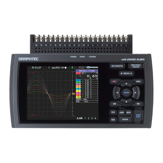
1. CONFIGURATION 1. CONFIGURATION 1.1 Model Configuration GL820 : 20-channel model with color monitor and internal memory 1.2 Accessories and Options Model Unit name Description name Logic / Alarm cable B-513 DC Drive Cable B-514 Same as GL200/450/500 Battery Pack... - Page 8 1. CONFIGURATION GL820-UM-251-9370...
-
Page 9: Upgrading The Firmware
2. UPGRADING THE FIRMWARE The version of your GL820’s firmware can be upgraded by rewriting the flash ROM on the pertinent circuit boards. You can upgrade the firmware by loading the update program to a USB memory device. 2.1 Note for the firmware upgrading •... - Page 10 Note: Don't turn off the GL820 until this process is finished. The following message will appear on the GL820 display in yellow characters when the upgrade is complete. Also the beeper will sound for 5 seconds. “Please Turn Off the Power.
- Page 11 (5) Turn off the power to the GL820 when the above message is displayed or when the beeper sound stops. Delete the two program files from a USB memory device. This is to avoid upgrading the firmware by mistake. GL820-UM-251-9370...
-
Page 13: Disassembly And Reassembly
• During reassembly, double-check to ensure that the proper cables have been correctly re-connected to the pertinent connectors. • Some areas of the control panel unit possess a high electrical potential, so exercise caution to avoid an electrical shock. GL820-UM-251-9370... -
Page 14: Removing The Input Terminal Unit
Pull the terminal unit out towards the direction indicated by the arrow while pressing the two locks at the bottom of the unit. (1) Press the two locks in the direction indicated by arrows. (2) Pull the unit out towards the direction indicated by the arrow. GL820-UM-251-9370... -
Page 15: Removing The Side Pads
(1) Peel off the left and right side pads from the main unit. Right side pad Left side pad Main unit Re-assembly (1) Push the left and right side pads against the main unit and then install them on the main unit. GL820-UM-251-9370... -
Page 16: Disassembling The Top Cover And The Bottom Case Assembly
(4) Disconnect the connector between the main control board and the AMP board and then remove the top cover assembly. Top cover assembly Bottom case assembly M2L8 self-tapping screw Re-assembly (1) Re-assemble the top cover assembly and the bottom case assembly in the reverse order in which they were disassembled. GL820-UM-251-9370... -
Page 17: Replacing The Main Control Board
(6) Disconnect the connector between the main control board and the control panel board and then remove the top cover assembly. Fixing tape M2L6 self-tapping screw Core Main control board LED flexible cable Top cover assembly Re-assembly (1) Re-assemble the main control board in the reverse order in which it was disassembled. GL820-UM-251-9370... -
Page 18: Replacing The Control Panel Board
(6) Remove the control panel board from the top cover assembly. M2L6 self-tapping screw LCD bracket M2L6 self-tapping screw Control panel board Top cover assembly Re-assembly (1) Re-assemble the control panel board in the reverse order in which it was disassembled. GL820-UM-251-9370... -
Page 19: Replacing The Lcd And The Top Cover
(4) Remove the key pad from the top cover assembly. LCD bracket Control panel board Key pad Top cover assembly with LCD Re-assembly (1) Re-assemble the LCD and the top cover assembly in the reverse order in which it was disassembled. GL820-UM-251-9370... -
Page 20: Replacing The Amp Board
M2.6L6 binding head screw Terminal unit connector cover Bottom case assembly Re-assembly (1) Re-assemble the AMP board in the reverse order in which it was disassembled. (2) Perform the Setup operations for the GL820 when you replace the AMP board. GL820-UM-251-9370... -
Page 21: Setup Procedures
(4) Press the [ENTER] key to display the menu from which you can execute the various Setup operations. Setup mode Setup1 (Basic) Setup2 (Room temp.) Setup3 (RTD temp.) (5) Select the Setup mode using the [Direction] keys, and then press the [ENTER] key. GL820-UM-251-9370... - Page 22 4. SETUP PROCEDURES (6) Move the cursor to the “Execute Setup” position as shown below. (7) Press the [ENTER] key to start the selected Setup operation. GL820-UM-251-9370...
-
Page 23: Ac Line Cycle Setting
4. SETUP PROCEDURES 4.2 AC Line cycle Setting You must set the AC Line cycle setting of the GL820 to the same cycle as that of your AC line before you perform the Setup operations. How to set the AC line cycle (1) Press the [MENU] key until the "OTHR"... -
Page 24: Performing Setup1 (Voltage Input)
• Have a voltage generator on hand that can output voltage up to 50 VDC (four-digit output). • Mutually connect the ground terminals of the voltage generator and the GL820. • Set the AC Line cycle setting of the GL820 to the same cycle as that of your AC line. Wiring connection Voltage generator 0.00000 V... - Page 25 4. SETUP PROCEDURES Setup procedure (1) As shown in the figure above, connect the output of the voltage generator to the GL820’s CH1 input terminal. (2) Leave the GL820 turned on for at least minutes. And leave the GL820 turned on for at least minutes after wiring.
- Page 26 (8) Press the [START] key and then wait until the "20 mV : [START]" message appears. Specify the voltage generator's output voltage setting to correspond to one of the displayed voltage ranges in the following table, and then input that voltage to the GL820. Message Input Voltage 0.000 mV 20 mV 20.000 mV...
- Page 27 Press the [ENTER] key to begin writing the new Setup data to the EEPROM. Message (11) After the setup parameters have been registered to the EEPROM, the display closes and returns to normal mode. (12) Turn off the GL820. This completes the voltage amp setup. GL820-UM-251-9370...
-
Page 28: Performing Setup2 (Room Temperature Compensation)
• As shown below, use (T: ø0.32 mm, K: ø0.65 mm) temperature compensation leads to connect the input terminals to the 0˚C reference temperature device (Zero controller). • Set the AC Line cycle setting of the GL820 to the same cycle as that of your AC line. Wiring connection Input 0 V for the output side or short the + and - terminals 0˚C reference... - Page 29 4. SETUP PROCEDURES Setup procedure (1) As shown in the figure above, connect the inputs of the zero controller to the GL820’s input terminals. (2) Leave the GL820 turned on for at least minutes. And leave the GL820 turned on for at least minutes after wiring.
- Page 30 [ENTER]" message appears. Message (8) Press the [ENTER] key to begin writing the new Setup data to the EEPROM. (9) After the setup parameters have been registered to the EEPROM, the display closes and returns to normal mode. GL820-UM-251-9370 4-10...
- Page 31 :Sensor1 Area :Area2 :CH 1 (11) Repeat steps (4) to (8) for all the areas up to Area 4. (12) Turn off the GL820. This completes the Room temp. setup. Setup flow for the Room temp. Procedure Selected area Area 1...
-
Page 32: Performing Setup3 (Rtd)
Reference resistors: 0 Ω (Short), 350 Ω ±0.01%, 2500 Ω ±0.01% • As shown below, use reference resistors to connect the CH20. • Set the AC Line cycle setting of the GL820 to the same cycle as that of your AC line. Wiring connection Reference resistors: (1) 0 Ω... - Page 33 4. SETUP PROCEDURES Setup procedure (1) As shown in the figure above, connect the reference resistor to the GL820’s input terminals. (2) Leave the GL820 turned on for at least minutes. And leave the GL820 turned on for at least minutes after wiring.
- Page 34 (10) The "EEPROM : [ENTER]" message appears when the 2500 ohm setup was completed. Message (11) Press the [ENTER] key to begin writing the new Setup data to the EEPROM. (12) After the setup parameters have been registered to the EEPROM, the display closes and returns to normal mode. GL820-UM-251-9370 4-14...
- Page 35 4. SETUP PROCEDURES (13) Turn off the GL820. This completes the RTD temp. setup. GL820-UM-251-9370 4-15...
-
Page 37: Inspection And Check Procedures
5.1 Preparations for inspections 5.1.1 AC Line Setting (1) Set the AC Line cycle setting of the GL820 to the same cycle as that of your AC line (See Section 4.2). 5.1.2 Sampling setting (1) Set the Sampling setting of the GL820 to at least 1 sec or longer. -
Page 38: How To Load The Condition Settings File To The Gl820 From A Usb Memory Device
5. INSPECTION AND CHECK PROCEDURES 5.1.4 How to load the condition settings file to the GL820 from a USB memory device (1) Connect the USB memory device to the GL820. (2) Press the [FILE] key to display the menu below. - Page 39 (4) Press the [ENTER] key to display the menu below. (5) Move the cursor to the “File Name” position using the [Direction] keys. (6) Press the [ENTER] key to display the menu shown below. (7) Move the cursor to the “USB1” position using the [Direction] keys. GL820-UM-251-9370...
- Page 40 (8) Press the [Left Arrow Direction] key to display files as shown below. (9) Specify the condition settings file to execute the various inspection operations by using the [DOWN Arrow Direction] key or the [UP Arrow Direction] key. (10) Press the [ENTER] key to display the menu shown below. GL820-UM-251-9370...
- Page 41 (11) Move the cursor to the “OK” position using the [Direction] keys. (12) Press the [ENTER] key to display the menu below. (13) Move the cursor to the “OK” position using the [Direction] keys. (14) Press the [ENTER] key to load the condition settings file. GL820-UM-251-9370...
-
Page 42: Voltage Measurement Accuracy
• Mutually connect the ground terminals of the voltage generator and the GL820 prior to initiating measurement. • Set the AC Line cycle setting of the GL820 to the same cycle as that of your AC line. • Set the Sampling setting of the GL820 to at least 1 sec or longer. - Page 43 5. INSPECTION AND CHECK PROCEDURES (4) Press the [DISPLAY] key until the menu shown below appears. (5) Press the [Left DOUBLE Arrow] key to display the menu shown below. GL820-UM-251-9370...
- Page 44 (8) Wait until the "Finished" message is displayed, and then display the values as shown below. Message Confirm that this value is within the above ratings after data has been captured. (9) Repeat steps (1) to (8), and then confirm that each value is within the above ratings. GL820-UM-251-9370...
-
Page 45: Temperature Accuracy
GL820 input terminals. • Set the AC Line cycle setting of the GL820 to the same cycle as that of your AC line. • Set the Sampling setting of the GL820 to at least 1 sec or longer. - Page 46 (6) Check that the level of measurement is within the above rating from the CH1 to the CH10. (7) Press the [CH GROUP] key to display from the CH11 to the CH20. Confirm that this value is within the above ratings after data has been captured. GL820-UM-251-9370 5-10...
-
Page 47: Rtd Accuracy
Reference resistors: 350 Ω ±0.01%, 2500 Ω ±0.01% • As shown below, use reference resistors to connect the CH20. • Set the AC Line cycle setting of the GL820 to the same cycle as that of your AC line. Wiring connection Same wiring connection as Setup3. - Page 48 Range Input resistor Factory Rating Product Rating Temperature Pt100 350 Ω 715.3 ˚C +714.5 ˚C to +716.1 ˚C +714.3 ˚C to +716.3 ˚C Pt1000 2500 Ω 408.8 ˚C +407.8 ˚C to +409.2 ˚C +408.0 ˚C to +409.6 ˚C GL820-UM-251-9370 5-12...
-
Page 49: Parts Lists
6. PARTS LISTS 6.1 Recommended Parts List Part No. Part Name Description Q'ty Remarks 795820700 Main Control Board with SD card, GL820 795820701 AMP Board, GL820 Same as GL800 795800702 Control Panel Board Japan 795800710 AC Adapter JP, with AC cable... -
Page 50: Parts Lists
6. PARTS LISTS 6.2 Parts Lists 6.2.1 Outer Casing Part No. Part Name Description Q'ty Remarks Rank 795820703 Top Cover with LCD 795820704 Bottom Case 604810510 Left Side Pad 604810520 Right Side Pad Outer Casing GL820-UM-251-9370... -
Page 51: Bottom Parts
6. PARTS LISTS 6.2.2 Bottom Parts Part No. Part Name Description Q'ty Remarks Rank 795820701 AMP Board 604810051 Cover, Connector Bottom Parts GL820-UM-251-9370... -
Page 52: Top Parts
795820700 Main Control Board, with SD card 795800702 Control Panel Board 795820703 Top Cover, with LCD 604820020 Bracket, LCD 604810033 Key Pad 562500097 Core, LCD Flexible Cable E04FG270712 690482010 Flexible Cable, LCD FC,RN8112-01 Top Parts Fixing tape for core GL820-UM-251-9370... - Page 53 SW1: Power Switch 561550037 Connector, HEC0470-01-640 JP14: DC Input 561500112 USB Type A Connector, XM7A-0442 J7: USB Connector 561500082 USB Type B Connector, XM7B-0442 J8: USB Connector 561550041 LAN Connector, TM11R-5M2-88-LP J9: LAN Connector 562070001 Backup Battery, ML2130-TT BAT1: Backup Battery GL820-UM-251-9370...
-
Page 54: Bottom Case
Remarks Rank 604220030 Cover, Battery 795820704 Bottom Case Bottom Case 6.2.5 Terminal Unit Part No. Part Name Description Q'ty Remarks Rank 795800707 Terminal Unit 795800705 Terminal Base 795800706 Terminal Base Plate Including 4 screws 795800708 Terminal Base Extension Cable GL820-UM-251-9370... -
Page 55: Standard Accessories
6. PARTS LISTS 6.2.6 Standard Accessories Part No. Part Name Description Q'ty Remarks Rank GL820-CDM01M CD Manual, Software English 604829040 GL820-UM-851 Quick Start Manual Japanese 604829030 GL820-UM-801 Quick Start Manual Japan 795800710 AC Adapter JP, with AC cable KSAH2400200T1M2 795800711... -
Page 57: Block Diagram
7. BLOCK DIAGRAM 7. Block Diagram 7.1 Main Unit Power Block & Main Control GL820-UM-251-9370... -
Page 58: Main Control Block
7. BLOCK DIAGRAM 7.2 Main Control Block GL820-UM-251-9370... -
Page 59: Amp Block
7. BLOCK DIAGRAM 7.3 AMP Block GL820-UM-251-9370... -
Page 60: Details Of The Amp
7. BLOCK DIAGRAM 7.3 Details of the AMP GL820-UM-251-9370...
Need help?
Do you have a question about the GL820 and is the answer not in the manual?
Questions and answers