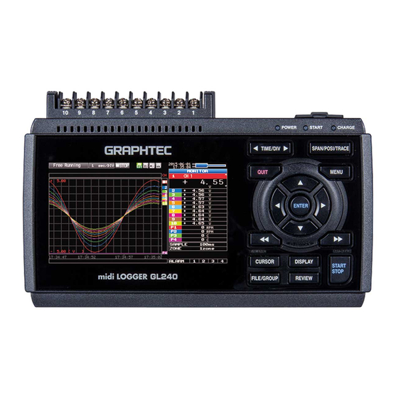
GRAPHTEC midi LOGGER GL240 Quick Start Manual
Hide thumbs
Also See for midi LOGGER GL240:
- User manual (152 pages) ,
- Q&a (38 pages) ,
- Quick start manual (24 pages)
Table of Contents
Advertisement
Advertisement
Table of Contents

Related Manuals for GRAPHTEC midi LOGGER GL240


Summary of Contents for GRAPHTEC midi LOGGER GL240
- Page 1 midi LOGGER GL240 Quick Start Guide 604249022 GL240-UM-852...
-
Page 3: Table Of Contents
Thank you for choosing Graphtec midi LOGGER GL240. The Quick Start Guide is to assist with the basic operations. Please refer to the USER'S MANUAL (PDF) in the CD-ROM for more in-depth information. Check the exterior of the unit to ensure that there are no cracks, defects, or any other damages before use. -
Page 4: Nomenclature
Nomenclature Top Panel Control panel keys Operation status LED • POWER • START • CHARGE SD CARD2 Wireless LAN connection terminal Wireless unit GND terminal (Option: when using the B-568) External input/output terminals Power jack for humidity sensor • LOGIC/PULSE Humidity sensor •... -
Page 5: Connection Procedures
DC voltage input For 4 to 20mA current to convert the signal to 1 to 5V. Note:Graphtec offers B-551 250 ohm precision shunt resister. Compensation wire is used if it is required. CAUTION: Connect wire to the designated channel, where individual channels are numbered. - Page 6 Internal memory • The internal memory is displayed as SD1 or SD CARD1 • The internal memory is not removable. Mounting SD CARD 2 < How to remove > < How to mount > (1) The SD memory card is (1) Open the protective cover to released by pushing SD CARD 2.
-
Page 7: Safety Guide For Using Gl240
Safety Guide for using GL240 Maximum input voltage If a voltage exceeding the specified value goes into the instrument, the electrical relay in the input will be damaged. Never input a voltage exceeding the specified value at any moment. < Between +/– terminals(A) > •... -
Page 8: Descriptions Of The Control Panel Keys
Descriptions of the Control Panel Keys (2) TIME/DIV (1) SPAN/POSI/TRACE (4) QUIT (3) MENU (5) DIRECTION KEYS + ENTER Password setting (6) ENTER (7) FAST FORWARD (KEY LOCK) (12) CURSOR (8) START/STOP (ALARM CLEAR) (USB DRIVE MODE) (11) FILE/GROUP (9) DISPLAY (10) REVIEW . - Page 9 . MENU Push the [MENU] key to open a setup menu. As you push the [MENU] key the setup screen tabs change in the sequence shown below. [Menu] Sequence • AMP Settings Set the input, range, filter , scaling, and other channel based settings.
- Page 10 . START/STOP (USB DRIVE MODE) Push the [START/STOP] key to initiate start and stop of a recording when GL240 is in the Free Running mode. If the key is pushed while turning the power to the GL240 on, the unit will switch from the USB connection to USB DRIVE mode.
-
Page 11: Descriptions Of The Menu Screens
Descriptions of the Menu Screens 5. Device access display 6. Device access display (Internal memory) (SD memory card 2 / wireless LAN display) 4. Wireless sensor display 7. Remote lamp 2. Time/DIV display area 8. Key lock lamp 1. Status message display area 3. -
Page 12: Measuring Procedure
Digital display area : Displays the input values for each channel. The keys can be used to select the active channel (enlarged display). The selected active channel is displayed at the very top of the waveform display. Quick settings : Displays items that can be easily set. The keys can be used to activate a Quick settings item, and the keys to change the values. -
Page 13: Setup : Menu Operation
2. Setup : Menu Operation Select the setting for only the channels being recorded. Make sure to turn off unused channels. It is unnecessary to change all settings from factory default. Key Pointers Basic Setup Menu Operation , [ENTER], and [QUIT] keys are used to set the condition on the setup menu. The current position of the cursor on the setup menu is displayed in green. - Page 14 4. Push the [MENU] key and open the "DATA" menu. 5. Set the sampling interval to "1s". Move the cursor to "Sampling" and then select "1s". 6. Set the Data Recording Medium to "SD memory card". Here, a sample folder "TEST" will be created in the internal memory (SDI), and then set the recorded data to be placed inside the "TEST"...
- Page 15 (6) Return to the Data Save Destination screen in (2). Next select the "TEST" folder and then push the [ENTER] key. (7) Move the cursor to and then push the [ENTER] key. Data records using the automatic file naming which includes date and time stamp in the internal memory (SD1).
-
Page 16: Data Record : How To Record
3. Data record : How to Record Once requied settings are stored,user can initiate the data recording while it is recording. Recorded data is available for replay. 1. Start recording (1) Push the [START/STOP] key. (2) A confirmation message is displayed. (3) Push the [ENTER] key to start recording. -
Page 17: Data Replay : How To Replay Recorded Data
4. Data Replay : How to Replay Recorded Data Once the recording is complete, the recorded file is saved in the “TEST” folder of the internal memory (SD1) set in “2. Setting” . File name is automatically assigned, in the GBD-format (Year,Month,Day – Time.GBD). -
Page 18: Additional Features
Additional Features GL240 has various functions that enhances and allows data to be collected and displayed more effectively. The following three functions describe these in details. Trigger Functions to Control Recording Start/Stop Operations 1. Starting data capture Trigger functions control the timing of the start of the data recording and the timing of the end of a data recording. - Page 19 (4) Move the cursor to the "Level" parameter next to the "Mode" parameter and then push the [ENTER] key. (5) The input box shown in the following screen is displayed. Select "20". Use the keys to move to the cursor to the second digit from the right, and the keys to change the value.
-
Page 20: Span, Position And Trace Functions To Adjust The Waveform Display
Span, Position and Trace Functions to Adjust the Waveform Display 1. Starting data capture Trigger functions can be used to control the timing of the start of a recording, and the timing of the end of a recording. Key Pointers The span, position and trace operations can be performed while the GL240 is in the Free Running mode, while it is recording data, replaying data. -
Page 21: Specifications
Specifications Standard Specifications Item Description Number of analog channels 10 channels External input and Trigger input or External sample pulse (1ch), Logic input (4ch) or Pulse input (4ch), Alarm output (4ch) output functions PC interface USB 2.0 (HighSpeed supported) , Wireless LAN (Required to install optional module.) Built-in memory device Internal memory (SD1) : approx. -
Page 22: Specification Of Input Section
Specification of the input section Item Description Number of input channels M3 screw type terminal (Rectangular flat washer) 10 channels Method Photo MOS relay scanning system, all channels isolated, balanced input Scan speed 10ms/1Ch Measurement Voltage 20/50/100/200/500 mV, 1/2/5/10/20/50/100 V, 1-5 V F.S. ranges Temperature Thermocouple : K, J, E, T, R, S, B, N, W (WRe5-26) -
Page 23: Installation Guide
To Install GL240 Application Software Follow the steps below for installation of application software for GL240. 1. Insert the accompanying midi LOGGER GL240 CD-ROM in the PC's CD drive. 2. Select [Start] > [Run] to open the [Run] window. 3. In the [Open] field, type in "D:\GL100_240_840-APS\Setup_English.exe" and push [OK]. - Page 24 Specifications are subject to change without notice. April 10, 2018 GL240 Quick Start Guide 1st edition-01 (GL240-UM-852) Publisher GRAPHTEC CORPORATION...
Need help?
Do you have a question about the midi LOGGER GL240 and is the answer not in the manual?
Questions and answers