GRAPHTEC GL260 User Manual
Midi logger
Hide thumbs
Also See for GL260:
- User manual (165 pages) ,
- Quick start manual (79 pages) ,
- Quick start manual (12 pages)
Table of Contents
Advertisement
Quick Links
Advertisement
Table of Contents

Subscribe to Our Youtube Channel
Related Manuals for GRAPHTEC GL260


Summary of Contents for GRAPHTEC GL260
- Page 1 GL260 USER’S MANUAL MANUAL NO.GL260-UM-151...
-
Page 2: To Ensure Safe And Correct Use
Conventions Used in This Manual To promote safe and accurate use of the GL260 as well as to prevent human injury and property damage, safety precautions provided in this manual are ranked into the five categories described below. Be sure you understand the difference between each of the categories. -
Page 3: Safety Precautions
GL260 and then connect its male plug into the electrical socket. • Use of the GL260 in such status may result in a fire hazard • For grounding, use a ground wire with a diameter of at least or electrical shock. - Page 4 Safety Precautions CAUTION CAUTION Do not use or store the GL260 in a location exposed to Do not place the receptacles containing fluid onto this direct sunlight or the direct draft of an air conditioner or device or close to this device.
- Page 5 • • It will cause the electric shock. It will cause the electric shock. • Ensure that the GL260’s power source is positioned so that it can easily be disconnected. Strict observance Strict observance Watch out for Watch out for...
- Page 6 Use prohibited Use prohibited This GL260 is not meant for use with lifesaving devices or devices with mission-critical high reliability or high safety requirements (medical devices, aerospace devices, shipping devices, nuclear power devices, etc.). In the event that this GL260 causes injury or property damage when used under these circumstances, the maker assumes absolutely...
-
Page 7: Introduction
Although the GL260 complies with the above-mentioned standards, be sure to use it correctly in accordance with the instructions and notes provided in this manual. Moreover, use of the GL260 by incorrect procedures may result in damage to the GL260 or may invalidate its safeguards. - Page 8 This transmitter must not be co-located or operated in conjunction with any other antenna or transmitter. 4. Notes for Safe Operation (1) Be sure to use the Graphtec-supplied AC adapter. In environments where there is a lot of noise or where the power supply is unstable, we recommend that you ground the GL260.
-
Page 9: Notes On The Use Of This Manual
(5) Do not use the GL260 in the vicinity of other devices which are susceptible to electromagnetic interference. (6) Measured results may not conform to the stated specifications if the GL260 is used in an environment which is subject to strong electromagnetic interference. -
Page 10: Table Of Contents
Contents Contents To Ensure Safe and Correct Use ........... . . Safety Precautions . - Page 11 Contents Chapter 3 Settings and Measurement Window names and functions ..........3.2 Key Operation .
- Page 12 Contents Chapter 5 Specification Standard Specifications ........... . . Standard Specifications .
-
Page 13: Chapter 1 General Description
Chapter 1 General Description This chapter provides a general description of the GL260 and its features. PRODUCT SUMMARY Overview Features Operating Environment Notes on Temperature Measurement Notes on Using the Monitor Changing the Display Language... -
Page 14: Overview
• The GL260 is equipped with the relay recording function, and 2000MByte or more data can be saved by switching to the other file without data missing. (When the capacity of one file reaches 2000MByte, the file is switched.) Data Control &... -
Page 15: Operating Environment
Wait until the condensation has disappeared before turning on the power. Warming-up Before Use The GL260 should be allowed to warm up with the power turned on for approximately 30 minutes to ensure that it operates according to the specified performance. -
Page 16: Configuration When In Use
CHAPTER 1 General Description Configuration When in Use Do not use the GL260 standing upright or at an angle. It must always be laid flat or inclined on the stands. <Usage Configuration> Inclined leg 90° Laid flat Inclined on the stands Opening the stands •... -
Page 17: Notes On Temperature Measurement
Please observe the following precautions when performing temperature measurement. • Do not block the air vents. Always provide a space of at least 30 cm on all sides of the GL260. • For stabilized temperature measurement, allow the GL260 to warm up for at least 30 minutes after turning it on. -
Page 18: Chapter 2 Checks And Preparation
Chapter 2 Checks and Preparation This chapter explains how to check the main module's external casing and accessories, and how to prepare the main module for operation. PRODUCT SUMMARY Checking the Outer Casing Checking the Accessories Nomenclature and Functions Connecting the Power Cable and Turning on the Power Connecting the Signal Input Cables Logic Alarm Cable Connection and Functions Mounting the SD Memory Card... -
Page 19: Checking The Outer Casing
CHAPTER 2 Checks and Preparation Checking the Outer Casing After unpacking, check the GL260's outer casing before use. In particular, please check for the following: • Surface scratches • Other flaws such as stains or dirt Checking the Accessories After unpacking, check that the following standard accessories are included. -
Page 20: Nomenclature And Functions
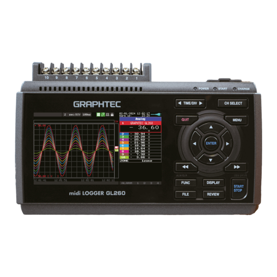
CHAPTER 2 Checks and Preparation Nomenclature and Functions This section describes the names and function of parts of the GL260. Operation status LED AC adapter jack • POWER ON when the power is ON Blinking while accessing to the memory USB interface terminals •... -
Page 21: Connecting The Power Cable And Turning On The Power
Connect the other end of the cable to ground. (4) Plug the AC cable into the mains power outlet. (5) Press the power switch on the GL260 to the ON side to turn on the power. CAUTION Always connect the GND terminal and refer to the safety precautions. - Page 22 (3) Connect the DC input side to the DC power supply. CAUTION Be sure to check the polarity of the wire tips when performing wiring. (4) Press the power switch on the GL260 to the ON side to turn on the power.
-
Page 23: Connecting The Signal Input Cables
This section describes how to connect the signal input cables. CAUTION During wiring, confirm that the signal's supply source is turned OFF to prevent electrical shocks. Also, position the GL260 input cable away from any power lines and ground cables. Terminal Configuration and Signal Types CH10... -
Page 24: Logic Alarm Cable Connection And Functions
Number of Output channels Output format Open collector output +5 V, 10 KΩ pull-up resistance * See the next page for details on alarm output CAUTION When the power is turned OFF or ON, the GL260 temporarily becomes the alarm state. - Page 25 CHAPTER 2 Checks and Preparation Internal equivalent circuit of I/O circuit Alarm output Maximum ratings of the transistor for alarm output VCEO (Collector-emitter voltage) : 30 V IC (Collector current) : 0.5 A + 5V PC (Collector dissipation) : 0.2 W * The maximum ratings must not be exceeded.
- Page 26 CHAPTER 2 Checks and Preparation Wiring Cable tips are bare tips. Perform wiring for the necessary functions. Signal Name Channel Number Wire Color Logic/Pulse input Orange with red dotted line Orange with black dotted line Grey with red dotted line Grey with black dotted line Alarm output White with red dotted line...
-
Page 27: Mounting The Sd Memory Card
CHAPTER 2 Checks and Preparation Mounting the SD Memory Card How to insert the SD memory card Insert the SD memory card into the SD CARD slot. CAUTION When the optional wireless LAN unit is installed, the SD memory card cannot be inserted. (1) Remove the SD CARD protective cover. - Page 28 CHAPTER 2 Checks and Preparation (3) Insert and close the protective cover into the upper hole and lower hole for the SD CARD protective cover. SD CARD Protective cover How to remove the SD memory card (1) Make sure that the SD memory card displayed on the screen is green, and the POWER LED lights up before removing it.
-
Page 29: Installing The Wireless Lan Unit (B-568: Option)
CHAPTER 2 Checks and Preparation Installing the Wireless LAN Unit (B-568: Option) To connect the GL260 to the wireless LAN, attach the wireless LAN unit to the wireless LAN connection terminal. SD CARD slot Wireless LAN connection terminal • CAUTION When the SD memory card has been inserted into the SD CARD slot, please remove the SD memory card. - Page 30 CHAPTER 2 Checks and Preparation (4) Align the wireless LAN unit to the wireless LAN connection terminal and the fixed guide and then insert the wireless LAN unit until the unit is locked. Fixed guide Wireless LAN connection terminal Fixed guide Wireless LAN unit CAUTION When the wireless LAN unit has been inserted, please be careful when handling so as not to hit and drop.
-
Page 31: Connecting To A Pc
Use the USB cable to connect the GL260 to a PC. Connection Using a USB Cable (1) This GL260 complies with the EMC Directive in the state when the supplied ferrite core is attached to the USB cable. To connect to the PC with the USB cable, attach the supplied ferrite core to the USB cable as shown in the following figure. - Page 32 For the insertion, refer to "2.8 Installing the Wireless LAN Unit (B-568: Option)". (1) Access point (operating as a base unit): The following devices and operating environment are required to connect the GL260 to a PC or smartphone via wireless LAN.
-
Page 33: Using The Battery Pack (B-573: Option)
CHAPTER 2 Checks and Preparation 2.10 Using the Battery Pack (B-573: Option) • The B-573 (optional) is the only battery type that can be used with the GL260. • Refer to "5.3 Accessories/Optional Accessories" for information on the battery run time. •... - Page 34 When a battery pack is installed: approx. 4.5 hours The battery pack is charged by mounting it in the GL260, attaching AC adapter to the GL260. (1) Mount the battery pack in the GL260 (see "Mounting the Battery Pack" in the previous page for the mounting procedure.).
-
Page 35: Connecting The Humidity Sensor
5V OUT terminal. Humidity sensor (B-530: Option) • CAUTION Do not use the sensor in a strong electrolyte environment. Measured results may not satisfy to the stated. • 5V OUT terminal on the GL260 is available for only one humidity sensor. 2-18... -
Page 36: Precautions To Observe When Performing Measurement
CHAPTER 2 Checks and Preparation 2.12 Precautions to Observe When Performing Measurement Please be sure to read the following carefully in order to prevent electric shocks or shorts. • CAUTION Do not apply radio-frequency signals with high voltage (50 KHz or above). •... - Page 37 Before starting another measurement operation, short-circuit the + and – terminals to enable self-discharge. The GL260 has a scan system. While in the status (open) in which signals are not input to the input terminal, measured results may be influenced by signals from other channels.
-
Page 38: Noise Countermeasures
Connect the signal chassis GND to the measurement device chassis ground. Use a short, thick lead to connect the chassis GND of the measurement object to the GL260’s chassis GND. It will become even more effective if the ground potentials are the same. -
Page 39: Setting The Date And Time
CHAPTER 2 Checks and Preparation 2.14 Setting the Date and Time If you are using the GL260 for the first time, charge the internal rechargeable battery and then make the date and time settings. CAUTION If the GL260 is not used for a period of approximately six months, the internal rechargeable battery may be discharged and the date and time may revert to the initial settings. -
Page 40: Window Names And Functions
Chapter 3 Settings and Measurement This chapter describes the setting and measurement procedures for the GL260. PRODUCT SUMMARY Window names and functions Key Operation Operation Modes Setting Menus WEB Server Function List of Error Codes... - Page 41 * : Displayed when performing the capturing stop process. : Appears when the GL260 waits for you to press the [START/STOP] key to stop it after data capture. * : Displayed when the data in the internal memory is replayed.
- Page 42 : Indicates remote mode. With some exceptions, operations must be conducted on a PC. When you cancel the connection on the application (GL28-APS), the GL260 is automatically sent back to local mode. If local mode is not entered, press the [QUIT] key.
- Page 43 Chapter 3 Settings and Measurement 8. Clock display/Warm-up time Displays the current date and time. Refer to "6. OTHER settings" in "3.4 Setting Menus" for details on date and time settings. From the time the power is turned on until the time set in the warm-up setting, the current date and time are displayed in the upper row, and the remaining warm-up time is displayed in the lower row.
- Page 44 Chapter 3 Settings and Measurement <Digital display enlargement function> If the number of CH displayed at one time is within 5 channels, the digital display will be enlarged. [Normal display] [Enlarged display] <Span/Position/Trace settings> Pressing the [ENTER] key during waveform display displays Span/Position/Trace settings. For details, refer to "3.4 Setting Menus"...
- Page 45 Chapter 3 Settings and Measurement 13. Pen display Displays the each channel signal position, trigger position, and alarm range. Trigger position Alarm range Rising Falling Win In Win Out Stop position Start position 14. Time stamp Displays the time stamp of a currently displayed waveform as time. This indicator shows that the measurement data was captured at 16:35:44.
- Page 46 Chapter 3 Settings and Measurement 18. Scale upper limit Displays the scale upper limit of the currently active channel. 19. Data capture bar <During data capture> Displays the elapsed time and the internal memory and SD memory card usage status. Elapsed time Remaining time for data capture Amount of internal memory...
-
Page 47: Key Operation
Chapter 3 Settings and Measurement Key Operation This section describes key operation. 2. TIME/DIV 1. CH SELECT 3. MENU 4. QUIT 5. Direction Keys 6. ENTER 7. FAST REWIND/FORWARD key (KEY LOCK) 11. FUNC 8. START/STOP (USB DRIVE) 12. FILE 9. - Page 48 Chapter 3 Settings and Measurement 2. TIME/DIV Press the left/right key of the [TIME/DIV] key to change the time axis display width. TIME/DIV display 3. MENU Open the settings window to capture data. For details on settings, refer to "3.4 Setting Menus"...
- Page 49 Since the SD memory card is recognized as a removal disk, this mode facilitates file manipulation such as transfer and deletion. (1) Use a USB cable to connect the GL260 and a PC. (2) While pressing the GL260 [START/STOP] key, turn the power ON.
- Page 50 Chapter 3 Settings and Measurement 9. DISPLAY This key is used to switch the screen mode. You can switch the window mode during Free Running (when capturing is stopped) and Capturing. Pressing this key switches the screen display as follows: <Waveform + Digital Screen>...
- Page 51 To exit the replay display, press the [QUIT] key. CAUTION For CSV-formatted data, only the data captured by this GL260 can be replayed. Also, when the data captured in CSV format is replayed, the unit of the temperature data is displayed in "deg C"...
- Page 52 Chapter 3 Settings and Measurement 11. FUNC You can use convenient function (FUNC function) that can be operated according to the current situation. Press the "FUNC" key to display the currently operable functions at the bottom right of the screen. Select the function you want to execute with the " "...
- Page 53 Chapter 3 Settings and Measurement Basic Procedures Used in Settings The following are basic operation procedures for settings. (1) Press the [MENU] key to open each menu. You can move between menu tabs by pressing the [MENU] key several times or by pressing the "...
-
Page 54: Operation Modes
Chapter 3 Settings and Measurement Operation Modes You can check the system operation status in the status message display. < Free Running > < Capturing > <Replaying while capturing data> < Replaying > Operation Description Simple message display Free Running Startup status, or data is not being captured. - Page 55 Chapter 3 Settings and Measurement 1. Free Running <Display when CH1 is selected on Free running waveform + Digital screen> The selected channels are displayed with a colored frame. The selected channel can be switched by operating the " " keys. The scale of the selected channel is indicated.
- Page 56 • CAUTION For CSV-formatted data, only the data captured by this GL260 can be replayed. Also, when the data captured in CSV format is replayed, the unit of the temperature data is displayed in "deg C" rather than "°C". •...
-
Page 57: Setting Menus
Chapter 3 Settings and Measurement Setting Menus When you press the [MENU] key during Free Running, the following menu screens appear. DATA TRIG ALARM OTHER 1. AMP settings This menu is used to specify input signal-related settings. <Analog settings> <Logic Pulse settings> <Calculation settings>... - Page 58 Chapter 3 Settings and Measurement Setting Selections available Logic/Pulse Mode Off, Logic, Pulse Logic Filter Off, On Misc. Waveform color 0 to 31 for each of red, green, blue (RGB) setting Trace setting Off, On Pulse Input Off, Revolution counts, Counts, Inst. Filter Off, On Slope...
- Page 59 Chapter 3 Settings and Measurement Switching displays Switching between Analog, Logic/Pulse and Calculation is as follows. <During displaying analog CH> <During displaying logic/pulse CH> <During displaying calculation CH> Analog settings Specifies the conditions for analog signals. When you use CH ALL to set an input, range and filter, all channels are set to the same values if the input is the same.
- Page 60 Chapter 3 Settings and Measurement 1-3. Range This is used to select the range of measurement. Input item Description 20, 50, 100, 200, 500mV; 1, 2, 5, 10, 20, 50, 100V 1-5V TEMP No selection (2000°C fixed) No selection (100% fixed) Available SPAN Settings <Voltage Ranges>...
- Page 61 A moving average is calculated 20 times per sampling interval. A moving average is calculated 40 times per sampling interval. <Filter processing> Filter processing performed on the GL260 is the moving average shown in the following figure. If the filter setting is 5, The moving average is "D=((n-4)+(n-3)+(n-2)+(n-1)+ n)÷5".
- Page 62 The Scaling function performs calculation using a ratio of the Meas. Value and EU Output Value settings. • The digital display shows "++++/––––" when the converted value cannot be processed by the GL260. • The span may be changed depending on the Scaling settings.
- Page 63 Chapter 3 Settings and Measurement 1-6. Misc. Setting object Setting Description Voltage, humidity Annotation Settings Set the annotation (comment) displayed in the CH. Span Settings Set the upper and lower limits of values of a span in which a waveform should be displayed.
- Page 64 Chapter 3 Settings and Measurement Logic and Pulse settings Makes settings related to digital input. <For Pulse> <For Logic> 1-7. Mode This is used to select the processing method for digital input. Selection item Description Digital input measurement is disabled. Logic Digital input is processed as logic signals.
- Page 65 The Scaling function performs calculation using a ratio of the Meas. Value and EU Output Value settings. • The digital display shows "++++/––––" when the converted value cannot be processed by the GL260. • The span may be varied depending on the scaling settings.
- Page 66 Chapter 3 Settings and Measurement 1-12. Misc. <For Pulse> <For Logic> Setting Description Waveform Color Setting 0 to 31 for each of red, green, blue (RGB) Trace This is used to set the waveform display. Span Setting Auto adjustment Automatically adjusts the span value based on the displayed data. Upper limit Set the span upper limit.
- Page 67 Chapter 3 Settings and Measurement Calculation settings 1-13. Calculation Make settings related to calculation. Setting Description Setting Off, On (when inter-CH Op. setting is formula or 4-point input) Misc. Set annotation, waveform color, line thickness and trace. <Calculation Off settings> <Calculation formula settings>...
- Page 68 Chapter 3 Settings and Measurement Setting Description Auto adjustment Adjust the span range based on the displayed measurement value. Upper limit Set the upper span value to be displayed the waveform. The set value is the value for the calculation result. Decimal point 1.0000, 10.000, 100.00, 1000.0, 10000.
- Page 69 Chapter 3 Settings and Measurement Setting Description Lower limit Set the lower span value to be displayed the waveform. The set value is the value for the calculation result. Unit selection Select the unit for displaying the calculation result. Voltage, Current, Length, Area, Volume, Velocity, Accel, Freq, Mass, Energy, Pressure, Flow, Temp, Strain, Brightness, Concentration Unit Select the unit after conversion.
-
Page 70: Data Settings
File Type GBD, CSV Set the file format used to save data. GBD: Creating a data file in Graphtec's proprietary binary format * It is not possible to change the data. CSV: Creating a data file in text format Name Type Auto, Arbitrary, Sequential number Set how a data file should be named. - Page 71 Chapter 3 Settings and Measurement 2-1. Sampling interval This is used to set the sampling interval for data capture. The table below shows the number of measuring channels* and sampling interval values that can be set. If data fluctuate due to noise, set the sampling interval to a value which enables the digital filter function. Number of Measuring Sampling Interval which enables Allowed Sampling Interval...
- Page 72 Chapter 3 Settings and Measurement 2-3. AC line filter Sets whether to enable or disable the AC line filter when external sampling is enabled. Enable this setting to enable the digital filter. When you use external sampling and measure signals with high noise levels, set the AC line filter to On.
- Page 73 Chapter 3 Settings and Measurement 2-4. Captured data file name This is used to select the name of a file or folder to which you want to save capture data. <If the naming method is Auto> <If the naming method is Arbitrary> Setting Description Folder...
- Page 74 Chapter 3 Settings and Measurement 2-5. Option Set the Ring, Relay, Backup, Data corruption check function. <Ring/Relay Ring Off> <Ring/Relay Ring> <Ring/Relay Relay/Capacity> <Ring/Relay Relay/Time> Setting Selections available Ring/Relay capturing Set the capturing function. Off: The capturing function is disabled. Ring: The ring capturing is executed.
- Page 75 Chapter 3 Settings and Measurement 2-6. Ring/Relay capturing settings Ring Capture Function Start capturing data Captured data is saved into the File 1. When the specified number of data are saved into the File 1, the captured data is saved into the File 2. The number of data is specified in the “Ring Capture Points”...
- Page 76 Chapter 3 Settings and Measurement Relay Capture Function Files are separated by the set file size or capturing time unit and captured continuously without missing any data. (The capacity for one file is 10MB to 2GB, and the capturing time is 1 hour to 24 hours.) When memory loop is set to Off Start capturing data Captured data is saved into the File 1.
- Page 77 Chapter 3 Settings and Measurement 2-7. Backup setting The GL260 has a function that periodically backs up captured data. Automatic backup to an FTP server Ethernet FTP server GL260 The data is backed up automatically to the internal memory (MEM) or SD CARD (SD) Measurement input •...
-
Page 78: Trig Settings
Chapter 3 Settings and Measurement 3. TRIG settings Set the trigger conditions. Setting Selections available Start Side Source Setting Off, Level, Alarm, External Input, Date, Weekly, Time Level Mode Analog: Off, H, L, Window In, Window Out Logic: Off, H, L Pulse: Off, H, L, Window In, Window Out Combination Level OR, Level AND, Edge OR, Edge AND... - Page 79 The repeat function is disabled. The repeat function is enabled. After one capture is ended, the next capture is started (If the start side source setting is not Off, the GL260 waits for a trigger). When setting to the specified time, the date and time must be set. However, when the repeat function is enabled (On), the specified time is changed to the time display.
-
Page 80: Alarm Settings
Chapter 3 Settings and Measurement 4. ALARM settings Make alarm settings. Setting Selections available Mode Analog: Off, H, L, Window In, Window Out Logic: Off, H, L Pulse: Off, H, L, Window In, Window Out Level Set numeric value Output 1, 2, 3, 4 Misc. - Page 81 Chapter 3 Settings and Measurement 4-4. Alarm History Set how to use the Alarm History function. Alarm History function When the Alarm History function is enabled, up to the latest 100 events for alarm occurrence/clearing can be saved. During data capturing, you can check the events that have occurred. During data replaying, you can check the event that occurred and move the cursor to the point where the event occurred.
- Page 82 Chapter 3 Settings and Measurement Alarm History screen The Alarm History screen can be displayed by pressing the "DISPLAY" key several times during data capturing. When capturing data When replaying data <Waveform + Digital> <Waveform + Digital> <Waveform enlargement> <Alarm History> <Digital + Calculation>...
- Page 83 Chapter 3 Settings and Measurement Description of the alarm history screen <Capturing> <When replaying data> Alarm occurrence/clearing Alarm occurrence/clearing Event date and time Cause of event Event date and time Cause of event Selection cursor Display Description Event date and time Date and time when the alarm event occurred.
- Page 84 Chapter 3 Settings and Measurement Trigger level settings/Alarm level settings Specifies detailed conditions for each channel when the start and stop side source settings are Level. The configuration of the level trigger is as shown in the figure below. <For trigger> <For alarm>...
- Page 85 Chapter 3 Settings and Measurement Level and Edge operations In the Level operation, a trigger is assumed to be generated if the trigger/alarm conditions are met when the [START] key is pressed. In the Edge operation, even if the trigger/alarm level achieves to the trigger/alarm generation level when the [START] key is pressed, it is not considered the trigger/alarm condition is satisfied if the level does not exceed the set level.
- Page 86 Chapter 3 Settings and Measurement Dead zones of trigger and alarm levels Trigger and alarm levels are provided with a dead zone in order to prevent false detection due to noise. The following figure shows the dead zone. Mode: Rising A trigger (alarm) does not occur because the input signal is not Trigger (alarm) point...
-
Page 87: Interface Settings
Chapter 3 Settings and Measurement 5. Interface settings This menu is used to specify conditions for PC connection. When the wireless LAN unit is installed, wireless LAN settings are displayed. <When the wireless LAN unit is not installed> <When the wireless LAN unit is installed> Setting Description Interface settings... - Page 88 Chapter 3 Settings and Measurement WLAN settings (Access point) Setting Description Wireless LAN Switch between Off, Station and Access point. Select the setting you want to change and execute "Wireless LAN restart". Automatic setting (WPS) WPS system Push button method, PIN method SSID input Character string: up to 32 characters Encryption method...
- Page 89 Chapter 3 Settings and Measurement Setting Description E-mail Send Server Settings Easy setting Arbitrary, Simple send, gmail, yahoo.co.jp, yahoo.com, Office365 Send (SMTP) Server Name Enter up to 63-character string SMTP port number 0 to 65535 Time zone UTC-12:00 to UTC+13:00 SMTP setting SMTP authentication method Off, SMTP-AUTH...
- Page 90 Sets the USB ID number of GL260. Specify a number from 0 to 9 (default value: 0). To control more than one GL260 unit with one PC, assign a unique USB ID to each of them. 5-4. Wireless LAN setting This is used to set the conditions when connecting the GL260 to wireless LAN.
- Page 91 5-5. Station setting When connecting to the commercially available wireless LAN base unit and controlling multiple GL260s from PC, the e-mail send function of the GL260 and Internet connection are available. (The following conditions is required to use them.) •...
- Page 92 Chapter 3 Settings and Measurement (3) Search the SSID. Press the " " key. The searched SSID list is displayed after searching the SSID. In Step (2), when the SSID is selected from this list, the SSID will be automatically reflected. (4) Set the automatic setting (WPS).
- Page 93 Chapter 3 Settings and Measurement 5-6. TCP-IP setting Selection item Description IP address auto acquisition Do not use, Use Do not use: When you do not use "IP address auto acquisition", select "Do not use" and set the IP address, Sub-net mask, Port number, etc. Use: Select "Use"...
- Page 94 Chapter 3 Settings and Measurement 5-7. Access point setting The access point setting is a setting when the GL260 operates as a base unit. Wireless connection with a PC is possible using the GL260 as a base unit. When selecting the wireless LAN as a station and then restarting the wireless LAN, the following screen is displayed.
- Page 95 How to use WPS When setting a station, a wireless router with WPS function and GL260 are used, and when using an access point, the GL260 is used as the base unit to connect a PC, etc., and the connection settings are automatically made.
- Page 96 Chapter 3 Settings and Measurement 5.8. Network settings Make network settings for each server. FTP Client settings Make the settings for the backup destination FTP server. <FTP client settings> Selection item Description FTP client Destination FTP server Enter the domain name or IP address of the FTP server. (Up to 127 characters) User name Enter the user name of the FTP account.
- Page 97 Files/folders deletion • Files/folders creation • File name/folder name change To write to the GL260, you must change the login account. For the initial value for each anonymous connection setting, refer to the following. Anonymous connection Account name Password Limit...
- Page 98 The default is "GL260". E-mail settings Perform the settings to send the e-mail from the GL260. The e-mail with the notification setting information (Alarm, Low Battery, Low communication strength, Free space in the internal memory (MEM) or SD memory card (SD) (only when data capturing) is sent. In addition, when setting to the Periodic notification, the e-mail will be sent in the set time.
- Page 99 Set the mail destination server name. (Up to 63 characters) SMTP port number Set from 0 to 65535. Time zone Set the time zone for the region where the GL260 is used. SMTP SMTP Set the SMTP authentication method to Off or SMTP-AUTH.
- Page 100 Set the timeout time to disconnect the connection when no communication. * If communication is not established for 1.5 times the set time, the connection is disconnected. Serial number The serial number of the GL260 is displayed. Connection When executed a connection test, a message is displayed.
- Page 101 Character string: up to 127 characters Enter the domain name or address of the clock server (NTP server) to use. Time Zone UTC-12:00 to UTC+13:00 Set the time zone for the region where the GL260 is used. (Japan: +09:00) Synchronized 00:00 to 23:59 Time Set the time to synchronize with the clock server.
-
Page 102: Other Settings
Make function settings related to system operation. Custom Menu Select the function to use. Information The system information on the GL260, such as the firmware version is displayed. GAME Various games Select the game you want to play. Temperature settings... - Page 103 Burnout check is disabled. Periodical burnout check is conducted. CAUTION During a burnout check, voltage is applied to the GL260. Therefore, set Burnout to "Off" when GL260 is connected in parallel with other devices to avoid any effect from these voltages. 3-64...
- Page 104 Turns off the display if not operated for some time to extend the service life of the LCD screen. If the GL260 runs on a battery pack (B-573, option), the use of this function prolongs the drive time. 6-2-3. Background Color Sets the background colors of the waveform display area and the digital display area.
- Page 105 The frequency set here can be removed by the digital filter. Note that if you make a mistake in this setting, The GL260 cannot eliminate noise from the power supply. For the sampling speed at which the digital filter is enabled, refer to "2-1. Sampling Interval" above.
- Page 106 When measuring temperature using a thermocouple, the inside of the GL260 must be warmed up sufficiently. The warm-up time is displayed in the clock display on the upper right of the GL260 at the time set in this setting. Warm-up time...
- Page 107 Chapter 3 Settings and Measurement 6-4. Custom menu Select the functions to be used with the GL260. By turning off unused functions, unused functions are not displayed in the Setting Menu, etc. Display item Description Select from list Select the functions you do not want to use from the function list.
- Page 108 The revision of the firmware installed in the GL260 is displayed. System Control The version of the System Control FPGA installed in the GL260 is displayed. MAC Address The MAC address of the wireless LAN unit installed in GL260 is displayed.
-
Page 109: Span/Position/Trace Settings
Chapter 3 Settings and Measurement 7. Span/Position/Trace settings When the [ENTER] key is pressed on the waveform display screen during Free-running, capturing, replaying while capturing, or replay, the "Span/Position/Trace" setting screen is displayed. [ENTER] key The span of the active CH that was selected when the [ENTER] key was just pressed is initially selected. In the case of Analog, Pulse, Calculation <For Analog, Pulse, Calculation>... - Page 110 Chapter 3 Settings and Measurement 7-3. Auto span adjustment Automatically adjust the span value based on the displayed data. 7-4. Position Move the 0 position of the waveform. By pressing the " " and " " buttons, the 0 position of the waveform moves by 1 division of the chart grid. In practice, the span is adjusted so that the above action is achieved.
-
Page 111: File Menu
Chapter 3 Settings and Measurement 8. FILE menu The operations for file can be performed by pressing the [FILE] key. The display items vary depending on the operation mode of free-running, replaying, and capturing. <Free-running status > <During replay or dual-screen replay status> <Capturing status>... - Page 112 Chapter 3 Settings and Measurement <Example of operation procedure> Example of file/folder delete procedure is described. (1) Select the file/folder you want to delete. Move the cursor to the file or folder to be deleted in the file list and press the [ENTER] key to display the " "...
- Page 113 Setting Description File Type Sets the file format used to save data. GBD: Creating a data file in Graphtec's proprietary binary format. * Data tampering can be prevented. CSV: Creating a data file in text format. Name Type Sets how a data file should be named.
- Page 114 Chapter 3 Settings and Measurement 8-3. Remove/replace SD memory card The SD memory card (SD) can be replaced during saving the data in the SD memory card. Perform the card replacement according to the following procedure (1) Press the "FILE" key to open the FILE menu. (2) Press the [ENTER] key in the "Remove/Switch SD card".
- Page 115 * The file is created on February 1,2023,12:34:56 in this example. CND : Data format (GL260 setting file format) NCD :NCD: This is the communication setting file format of the GL260. User: Data is captured to a file with an entered file name.
- Page 116 Chapter 3 Settings and Measurement 8-7. Load Settings Loads and reflects the GL260 setting conditions from a file. Setting Description Folder The folder of the file specified in the FILE is displayed. Specify a folder to which you want to save data. For details, refer to "9. File dialog".
-
Page 117: File Dialog
Chapter 3 Settings and Measurement 9. File dialog This section describes how to specify the data save destination in the DATA menu, how to specify the data save destination in the FILE menu, and how to operate the file list. <Data save destination specification file dialog>... -
Page 118: Text Input
Chapter 3 Settings and Measurement 10. Text input Related to text input operations such as annotation, EU (scaling) unit and captured data file name input. <Character entering mode> <Clipboard mode> Operation selection Clipboard Character entering Operation mode Description Operation method Text input Upper case alphabet mode When the cursor key is moved to the uppermost part, the input character... - Page 119 Chapter 3 Settings and Measurement 10-1. Clipboard The clipboard is a function that allows you to store the character string that you have entered once and enter the same character string repeatedly. For example, if the CH annotation looks like this, there is a common character string. Contents of the annotation Channel Annotation CH1 Channel Annotation CH2...
- Page 120 Chapter 3 Settings and Measurement (6) Paste by pressing the "ENTER" key. Paste the character string. (7) Enter the rest of the character string and select "OK" to complete the settings. 10.2 Clipboard copy operation When copying to the clipboard, the four clipboard strings are as follows. Character string input field Clipboard 1 Clipboard 2...
-
Page 121: Data Replay Menu
When the data is corrupted: "Data is corrupted" is displayed. CAUTION For CSV-formatted data, only the data captured by this GL260 can be replayed. "Checksum verification" is displayed only when selecting a GBD file to which a checksum is attached. For how to add checksums, refer to "2-8. - Page 122 Chapter 3 Settings and Measurement Setting Selections available Data search Mode CH1 to CH10 H, L Logic H, L Pulse H, L Alarm Both, H, L Level CH1 to CH10 Set numeric value Pulse Set numeric value Next Search Select and press ENTER key to execute.
- Page 123 Chapter 3 Settings and Measurement 11-6. Date Search Sets the search conditions to be used in the next sections ("11-7. Find Next" and "11-8. Find Previous"). The operation is Edge operation. Selection item Description Sets the channel to be used for search. CH1-10: The specified analog channel is used for search.
-
Page 124: Quick Setting
Chapter 3 Settings and Measurement 12. Quick setting <Free Running> <Replay data> Screen Operation mode Sign Description Waveform Free Running ZONE Using the key, change the zone division. Capturing ZONE Using the key, change the zone division. Replaying during ZONE Using the key, change the zone division. -
Page 125: To Cancel Key Lock By Password
Chapter 3 Settings and Measurement 13. To cancel key lock by password A password can be set to GL260 to cancel the key lock. (No password is set at factory default.) <Operation flow> (1) Set the password. Press the "... -
Page 126: Qr Code
Chapter 3 Settings and Measurement 14. QR code Click the "HELP" mark icon in the menu of the GL260 to display the QR code. This QR code allows you to access the FAQ Q&A on our website. If you have any problems, read the QR code with your smartphone, etc., and check the Q&A on our website. -
Page 127: Web Server Function
– http ....Protocol to access the server. HTTP (Hyper Text Transfer Protocol) – IP address ..Enter in the IP address of the GL260 to monitor. – Port number ..Specify the port number. The port number is the number set to the GL260 or router, etc. - Page 128 Screen display ....Allows GL260 operation. Change settings ....You can check and change the settings of the GL260. File operation ....The data captured by GL260 can be downloaded to/deleted from the PC. CAUTION You may not be able to access the web page if you change the network or restart.
- Page 129 Chapter 3 Settings and Measurement Change settings AMP settings DATA settings TRIGGER settings ALARM settings I/F settings OTHER settings AMP settings ..... Make Analog input, Pulse, Logic and Calculation settings. DATA settings .... Make settings related to capturing. TRIGGER settings ..Make settings related to trigger. ALARM settings ..
- Page 130 Chapter 3 Settings and Measurement File operation Downloading multiple files Delete multiple files Folder/file display...By double-clicking the folder, you can display the files in the folder. Double-click the file to download the file. Download .......By right-clicking the file/folder and selecting "Download", you can download the file. If you select a folder, all files in the folder are downloaded.
-
Page 131: List Of Error Codes
Chapter 3 Settings and Measurement List of Error Codes If an error code is displayed on the GL260, please handle errors in reference to the table below. Error code Description –1 Please contact us. Please contact us. File not found. -
Page 132: Chapter 4 Example Of Use
Chapter 4 Example of Use This chapter provides simple examples of how to use the GL260. PRODUCT SUMMARY Capturing procedure Replay procedure Other functions... -
Page 133: Capturing Procedure
(2) Connect measurement object 2 to the 2CH terminal. (Temperature) (3) Connect to AC power. (4) Turn on the power. Connect securely! Measurement object (5) Wait at least 30 minutes for the GL260 to warm up. (Warm-up is required when performing thermocouple measurements.) -
Page 134: Settings
Chapter 4 Example of Use 2. Settings Only the settings necessary for capturing are made here. Use the default settings (factory settings) for other settings. Basic operation of the setting menu On the menu screen, use the " " keys, "ENTER" key, and "QUIT" key to operate. The current cursor position is displayed in "green". - Page 135 Chapter 4 Example of Use (4) Select the temperature with the " " keys. (5) Press "ENTER" key to confirm. AMP settings Make input settings for CH1 and CH2. Press the "MENU" key to open the AMP setting screen. <CH1 setting> (1) Move the cursor to the CH1 input and set it to "DC".
- Page 136 Chapter 4 Example of Use (2) Move the cursor to the CH1 range and set it to "1V". CH2 settings (1) Move the cursor to the CH2 input and set it to "TEMP". (2) Move the cursor to the CH2 sensor and set it to "TC-T". <Other CH settings>...
- Page 137 Chapter 4 Example of Use DATA setting Press the "MENU" key to open the DATA setting screen. Sampling interval setting Move the cursor to the sampling interval and set it to "1s". Data capturing destination setting Set the data capturing destination media, file format, and file naming method. (1) Set the capturing destination to "Internal memory".
- Page 138 Chapter 4 Example of Use (3) Set the naming method to "Auto". (4) Set the capturing destination folder. Move the cursor to the folder and press the "ENTER" key. (5) The Data saving destination specification dialog opens. In the Data saving destination specification dialog, set the capturing destination of the internal memory (MEM). * In the Data saving destination specification dialog, the folder name is enclosed in <...
- Page 139 Chapter 4 Example of Use (7) Here, create a "TEST" folder in the internal memory (MEM) and set so that data is saved in the "\MEM\TEST" folder. • Move the cursor to "A" in the character type selection using the " "...
-
Page 140: Capturing
Chapter 4 Example of Use 3. Capturing After the capturing settings are complete, start capturing. Start capturing (1) Press the "START/STOP" key. (2) A confirmation message is displayed. (3) Press the "ENTER" key to start capturing. Capturing state When capturing starts, the elapsed time and available capturing time are displayed. Elapsed time Available capturing time... - Page 141 Chapter 4 Example of Use Replaying during capture When you press the "REVIEW" key during capturing, replay can be performed during capture. While capturing data, you can replay the data from the beginning of the data to the point at which capturing was performed.
-
Page 142: Replay Procedure
Chapter 4 Example of Use Replay procedure 1. Replay procedure We explain the simple procedure for replaying the captured data. The captured data file uses the data captured in "4.1 Capturing procedure". The captured data files are stored in the "TEST\<date>" folder in the internal memory (MEM). Since the captured data file name was saved with an automatic file name function, a file named "Month/Day/Year-Time. - Page 143 Chapter 4 Example of Use (2) A file selection dialog is displayed. (3) Use the " " keys to move to the desired folder (\MEM\TEST\<date>), and use the " " keys to select the desired file. Use the " " key to move to the selected folder. "...
- Page 144 Chapter 4 Example of Use (4) Press the "ENTER" to confirm. This completes the replay file settings. Data replay (1) Move the cursor to "OK" using the " " keys. (2) Press the "ENTER" key to play the data. 4-13...
-
Page 145: Replay Screen
Chapter 4 Example of Use 2. Replay screen The data replay screen is described here. 1. Scrollbar 2. Level display 3. Quick settings 6. Cursor 4. Time display (absolute) 5. Time display (relative) Name Description 1. Scrollbar The position and width from the entire waveform range are displayed on the screen. The position of the A/B cursors are also displayed. -
Page 146: Finish Replaying
Chapter 4 Example of Use 3. Finish replaying We describe how to finish the data replay using the data replay screen. (1) Press the "QUIT" key during replay. (2) A confirmation message is displayed. Press the "ENTER" key to finish replaying. When the replay is finished, it will be in free running state. -
Page 147: Other Functions
The custom function is a function that hides the display of the function from the setting menu, etc. by setting the unused functions of the GL260 to OFF. By hiding the display of functions that are not used, the settings can be streamlined and unnecessary setting errors can be prevented. -
Page 148: Remote Control Service Cooperation Function
When the GL260 and PC are connected via USB, the GL260 can be recognized by the PC as a USB mass storage. This function allows you to access the data of the internal memory and SD CARD of the GL260 from a PC via USB. -
Page 149: Inter-Ch Operation Function
Chapter 4 Example of Use 7. Inter-CH operation function You can make the calculation result function as an independent CH and perform measurement while comparing it with the original waveform before calculation. Also, each calculation CH can be multiplied by a coefficient. You can add an offset at the end. CALC1 = (a ×... -
Page 150: Func Function
Chapter 4 Example of Use 10. FUNC function When you press the "FUNC" key, what you can do at that time is displayed the lower right corner of the screen. If you have trouble with the operation, we recommend pressing the "FUNC" key. 4-19... - Page 151 Chapter 5 Specification This chapter describes the basic specifications for the GL260. PRODUCT SUMMARY Standard Specifications Function Specifications Accessories/Optional Accessories External Dimensions...
- Page 152 Chapter 5 Specification Standard Specifications Standard Specifications Item Description Number of analog inputs 10 channels External input and output functions Trigger input or External sample pulse (1ch), Logic input (4ch) or Pulse input (4ch), Alarm output (4ch) Data backup functions Setup parameters: EEPROM/Clock: Lithium battery Clock accuracy (23°C environment) ±0.002% (accurate within about 50 seconds per month)
- Page 153 Wireless LAN (Option) Functions Data transfer to the PC (realtime, Internal memory or SD memory card data) PC control of the GL260 USB functions USB drive mode: Transfer and delete the captured data in the internal memory or SD memory card.
- Page 154 Chapter 5 Specification Input Unit Specifications Item Description Number of input channels 10 channels Input terminal type M3 screw type terminals (Rectangular flat washer) Input method Photo MOS relay scanning system All channels isolated, balanced input Scan speed 10 ms/1 ch maximum Measurement ranges Voltage: 20, 50, 100, 200, 500 mV, 1, 2, 5, 10, 20, 50, 100 V, 1-5 V F.S.
- Page 155 Relay recording The data is continuously captured in max. 2GB-separated files without missing data. Replaying data GBD/CSV-formatted data file (only data captured in this GL260) Calculation between CHs Operation type: Inter-CH (Four arithmetic operations) Target input: Analog CH1 to CH10...
- Page 156 Chapter 5 Specification External Input/Output Functions Item Description Input/output types • Trigger input (1 ch) or External sampling input (1 ch) • Logic input (4 ch) or Pulse input (4 ch) • Alarm output (4 ch) * Switch between Logic and Pulse * Switch between Trigger and External sampling.
-
Page 157: Control Software
The e-mail is sent to the specified address when the alarm monitor is performed. Accessories Item Description Quick Start Guide GL260-UM-8xx: 1 AC adapter 100 to 240 VAC, 50/60 Hz, Power supply cord for each area: 1 Ferrite core This is used to attach to the USB cable: 1... -
Page 158: Battery Pack B-573 (Option)
Chapter 5 Specification Battery Pack B-573 (Option) Item Description Capacity 7.2V/2875mAh Battery type Lithium secondary battery Running time When using the LCD display: approx. 6 hours When using the screensaver: approx. 7 hours * 1-sec sampling, capturing to internal memory, new battery pack, and +25°C environment. * The running time depends on the operating environment. - Page 159 Chapter 5 Specification List of Options Item Model Description Input/output cable for GL B-513 2 m long (no clip on end of cable) DC drive cable B-514 2 m long (no clip on end of cable) Humidity sensor * B-530 3 m long (with power plug) Wireless unit * B-568...
-
Page 160: External Dimensions
Chapter 5 Specification External Dimensions GL260 2-M4 thread (L5*) Unit: mm Dimension precision: Error ± 3 mm Terminals 7.62 Unit: mm Dimension precision: Error ± 0.5 mm 5-10... -
Page 161: Index
Index Index 3-17 Data replaying during capture ....3-82 Accessories ........Data replay menu . - Page 162 Index 3-51 Host Name ....... . Operating Environment ......2-10 3-35 How to insert the SD memory card .
- Page 163 Index Signal Input Cables ......Signal Types ....... . 3-25 Slope .
- Page 164 Specifications are subject to change without notice. GL260 User's Manual GL260-UM-151 September 25, 2023 1st edition-01 GRAPHTEC CORPORATION...
Need help?
Do you have a question about the GL260 and is the answer not in the manual?
Questions and answers