GRAPHTEC gl820 User Manual
Midi logger
Hide thumbs
Also See for gl820:
- Quick start manual (22 pages) ,
- Service manual (60 pages) ,
- Quick start manual (21 pages)
Table of Contents
Advertisement
Quick Links
Advertisement
Table of Contents

Related Manuals for GRAPHTEC gl820


Summary of Contents for GRAPHTEC gl820
- Page 1 GL820 USER’S MANUAL MANUAL NO.GL820-UM-151...
-
Page 2: Notes On Use
Notes for Safe Operation (1) Be sure to use the Graphtec-supplied AC adapter. In environments where there is a lot of noise or where the power supply is unstable, we recommend that you ground the GL820. - Page 3 Introduction (7) Insofar as possible, position the GL820 input signal cables away from any other cables which are likely to be affected by electromagnetic interference. (8) For stabilized measurement, allow the GL820 to warm up for at least 30 minutes after turning it on.
-
Page 4: To Ensure Safe And Correct Use
The following describes important points for safe operation. Please be sure to observe them strictly. Conventions Used in This Manual To promote safe and accurate use of the GL820 as well as to prevent human injury and property damage,safety precautions provided in this manual are ranked into the five categories described below. Be sure you understand the difference between each of the categories. -
Page 5: Safety Precautions
GL820 and then connect its male plug into the electrical socket. ● Use of the GL820 in such status may result in a fire hazard ● Use of the GL820 without the power cord securely plugged or electrical shock. - Page 6 Safety Precautions Safety Precautions CAUTION Do not use or store the GL820 in a location exposed to Do not place coffee cups or other receptacles containing direct sunlight or the direct draft of an air conditioner or fluid on the GL820.
- Page 7 Safety Precautions Memo...
-
Page 8: Table Of Contents
2 Checks and Preparation ................2−1 Checking the Outer Casing ........................2−2 Checking the Accessories ........................2−2 GL820 Nomenclature and Functions ....................2−3 Connecting the Power Cable and Turning on the Power ..............2−4 Connecting to an AC Power Supply ....................2−4 Connecting to a DC Power Supply ....................2−5 Connecting the Signal Input Cables ....................2−6... - Page 9 CONTENTS How to Recharge the Rechargeable Battery ................2−23 How to Set the Date and Time .....................2−23 3 Settings and Measurement ..............3−1 Window names and functions ......................3−2 Key Operation ............................3−6 (1) CH GROUP ..........................3−6 (2) SPAN/TRACE/POSITION ......................3−7 (3) TIME/DIV ..........................3−7 (4) MENU ............................3−7 (5) QUIT(LOCAL) ...........................3−8 (6) Direction keys ...........................3−8 (7) ENTER ............................3−8...
-
Page 10: General Description
CHAPTER 1 General Description This chapter provides a general description of the GL820 and its features. Overview Features Operating Environment Notes on Temperature Measurement Notes on Using the Monitor Changing the Display Language... -
Page 11: Overview
GL820 are provided with 20 channels as a standard measurement feature, or can be extended up to 200 channels by attaching additional terminal sets. GL820 are also equipped with an internal flash memory to store data and enable the direct capture of a large volume of data to USB memory. -
Page 12: Operating Environment
Wait until the condensation has disappeared before turning on the power. Warming-up Before Use The GL820 should be allowed to warm up with the power turned on for approximately 30 minutes to ensure that it operates according to the specified performance. -
Page 13: Notes On Temperature Measurement
If the screen saver operates, press any key to restore the display. • Condensation may form on the LCD screen if the GL820 is moved from a cold to a warm location. If this occurs, wait until the LCD screen warms up to room temperature. -
Page 14: Checks And Preparation
CHAPTER 2 Checks and Preparation This chapter explains how to check the GL820's external casing andaccessories, and how to prepare the GL820 for operation. Checking the Outer Casing Checking the Accessories GL820 Nomenclature and Functions Connecting the Power Cable and Turning on... -
Page 15: Checking The Outer Casing
CHAPTER 2 Checks and Preparation Checking the Outer Casing After unpacking, check the GL820's outer casing before use. In particular, please check for the following: ● Surface scratches ● Other flaws such as stains or dirt Checking the Accessories After unpacking, check that the following standard accessories are included. -
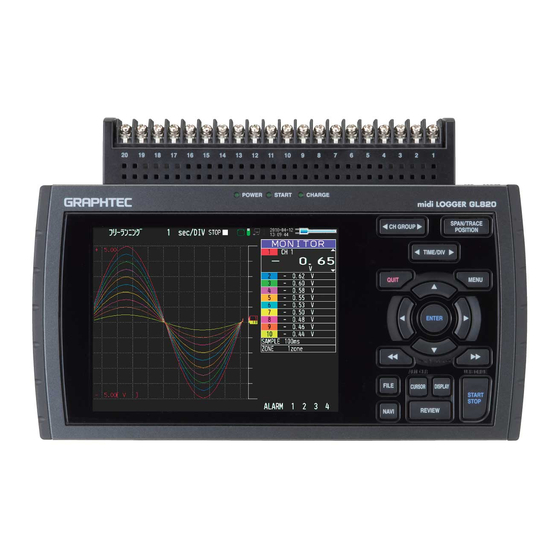
Page 16: Gl820 Nomenclature And Functions
CHAPTER 2 Checks and Preparation GL820 Nomenclature and Functions This section describes the names and function of parts of the GL820. Operation status LED Power switch PC interface terminals Monitor • POWER : ON when the power is ON • USB •... -
Page 17: Connecting The Power Cable And Turning On The Power
(4) Plug the AC cable into the mains power outlet. (5) Press the power switch on the GL820 to the ON side to turn on the power. Always connect the GND terminal and refer to the safety precautions. The GL820 must be grounded even when connected to other devices and sharing a common ground level. -
Page 18: Connecting To A Dc Power Supply
(3) Connect the DC input side to the DC power supply. Be sure to check the polarity of the wire tips when performing wiring. (4) Press the power switch on the GL820 to the ON side to turn on the power. 2−5... -
Page 19: Connecting The Signal Input Cables
CHAPTER 2 Checks and Preparation Connecting the Signal Input Cables This section describes how to connect the signal input cables. Terminal Configuration and Signal Types CH20 + − Connection diagram DC voltage input Thermocouple input Voltage input Compensationcopper wire Resistance temperature detector input Current input Direct current Lead wire resistance should... -
Page 20: Logic Alarm Cable Connection And Functions
CHAPTER 2 Checks and Preparation Logic Alarm Cable Connection and Functions The logic alarm cable (B-513: Option) enables logic/pulse input, external trigger input, and alarm signal output. Connect the logic alarm cable (B-513: Option) to the external input/output terminal as shown below. Logic alarm cable (B-513: Option) Logic/Pulse Specifications Item... -
Page 21: Internal Equivalent Circuit Of I/O Circuit
CHAPTER 2 Checks and Preparation Internal equivalent circuit of I/O circuit ● Alarm output Maximum ratings of the transistor for alarm output VCEO (Collector-emitter voltage) : 30 V IC (Collector current) : 0.5 A PC (Collector dissipation) : 0.2 W * The maximum ratings must not be exceeded. - Page 22 CHAPTER 2 Checks and Preparation Wiring Cable tips are bare tips. Perform wiring for the necessary functions. Signal Name Channel Number Wire Color Logic/Pulse output Orange with red dotted line Orange with black dotted line Grey with red dotted line Grey with black dotted line Alarm output White with red dotted line...
-
Page 23: Attaching Usb Memory
Inserting a USB Memory Attach the USB memory to the USB memory terminal. USB Memory When you attach the USB memory to GL820, be careful during handling so as not to bump or drop the unit. <Specifications of supported USB memory> •... -
Page 24: Connecting To A Pc
CHAPTER 2 Checks and Preparation Connecting to a PC Use the USB, LAN Interface to connect the GL820 to a PC Connection Using a USB Cable Use the USB cable to connect the GL820 to a PC. USB cable If the USB cable is used, the USB driver must be installed in your PC. Please refer to “USB Driver Installation Manual”... -
Page 25: Lan Connection
CHAPTER 2 Checks and Preparation LAN Connection Use a LAN cable to connect the GL820 to a PC. LAN cable Cable Types • Use a crossing cable when connecting directly to a PC, without using a hub. LAN cable (crossing) •... -
Page 26: Using The Battery Pack (B-517: Option)
CHAPTER 2 Checks and Preparation Using the Battery Pack (B-517: Option) ● The B-517 (option) is the only battery type that can be used with the GL820. ● Refer to the specifications (P.4-7) for information on the battery run time. -
Page 27: Charging The Battery
The battery pack is charged by mounting it in the GL820, attaching AC adapter to the GL820. (1) Mount the battery pack in the GL820 (see the previous section for the mounting procedure). (2) Turn on the power to the GL820. (Please see Section 2.4, “Connecting the Power Cable andTurning on the Power”). -
Page 28: Connecting The Humidity Sensor (Option)
Connecting the Humidity Sensor (Option) Connect the + and - lead wires of the humidity sensor (the B-530 option) to the desired terminals, and then insert the round connector into the 5V OUT connector on the GL820. Connected to the 5V OUT terminal. -
Page 29: Mounting And Removing The Terminal Unit
Mounting and Removing the Terminal Unit Remove and mount terminal units as shown below. Make sure the GL820’s power is OFF when removing or mounting terminal units. To Remove Pull the terminal unit out towards the direction indicated by the arrow while pressing the two locks at the bottom of the unit. -
Page 30: To Mount
CHAPTER 2 Checks and Preparation To Mount Insert the tabs at the top of the terminal unit into the slots of the GL820, and push in the unit until the lock tabs at the bottom of the unit are securely locked. -
Page 31: Mounting The Extension Terminal Base Set
2.12 Mounting the Extension Terminal Base Set (B-537) Mount the extension terminal base set as shown below. Make sure the GL820’s power is OFF when mounting the extension terminals. B-537 Set Contents Extension Terminal Base Unit : 1 Extension Terminal Cable : 1 To Mount (1) Remove the terminal unit mounted to the GL820 (refer to 2-11). -
Page 32: Mounting The 20 Channel Extension Terminal Set
2.13 Mounting the 20 Channel Extension Terminal Set (B-538) Mount the 20 channel extension terminal set as shown below. Make sure the GL820’s power is OFF when mounting the extension terminals. B-538 Set Contents Extension Terminal Base Unit : 1... - Page 33 (3) Connect the extension terminal cable to the extension terminal base unit. * Press in the cable until it is securely locked. Extension terminal cable (4) Connect the other end of the extension terminal cable to GL820. * Press in the cable until it is securely locked. Extension terminal cable...
-
Page 34: Precautions To Observe When Performing Measurement
Before starting another measurement operation, short-circuit the + and - terminals to enable self-discharge. The GL820 has a scan system. While in the status (open) in which signals are not input to the input terminal, measured results may be influenced by signals from other channels.In such a case, turn OFF the input setting or short circuit +/-. -
Page 35: Noise Countermeasures
Connect the signal chassis GND and the measurement device chassis ground. Use a short, thick lead to connect the chassis GND of the measurement object to the GL820’ chassis GND. It will become even more effective if the ground potentials are the same. -
Page 36: Setting The Date And Time
If the GL820 is not used for a period of approximately six months, the internal rechargeable battery may be discharged and the date and time may revert to the initial settings. If this happens, recharge the battery before using the GL820. -
Page 37: Settings And Measurement
CHAPTER 3 Settings and Measurement This chapter describes the setting and measurement procedures for the GL820. Window names and functions Key Operation Operation Modes Setting Menus WEB Server Function... -
Page 38: Window Names And Functions
*: Capture stop processing or other cases when data is being written to the built-in internal memory or USB memory : Appears when the GL820 waits for you to press the Start/Stop key to stop it after data capture. : Appears while the data in the internal memory is being replayed. - Page 39 : USB memory is inserted but is not accessed. : USB memory is being accessed. Do not remove the USB memory. Do not remove the USB memory or turn off the power of the GL820 while the USB memory is being accessed.
- Page 40 CHAPTER 3 Settings and Measurement 8. Clock display Displays the current date and time. Refer to page 3-39 for details on setting the date and time. 9. AC/battery display : Running on AC or DC power supply. : Running on the battery. The remaining battery power is 100 to 91%. : Running on the battery.
- Page 41 CHAPTER 3 Settings and Measurement 14. File name display (1) During data capture A capture file name is displayed during capture. * If the ring capture setting is ON, a file name displayed during capture ends with "_RINGx" (x represents a number) but the actual file name does not include "_RINGx".
-
Page 42: Key Operation
CHAPTER 3 Settings and Measurement Key Operation This section describes key operation. (1) CH GROUP (2) SPAN/TRACE/POSITION (3) TIME/DIV (4) MENU (5) QUIT (6) Direction Keys (7) ENTER (8) FAST FORWARD key (KEY LOCK) (9) START/STOP (USB DRIVE) (13) FILE (14) NAVI (12) CURSOR (ALARM CLEAR) (11) DISPLAY... -
Page 43: Time/Div
CHAPTER 3 Settings and Measurement (2) SPAN/TRACE/POSION Switches the display in the digital display. Used to change the settings related to waveform display during Free Running (when stopped), data capture and data replay. Pressing this key will switch displays as shown below. MONITOR SPAN POSITION... -
Page 44: Quit(Local)
CHAPTER 3 Settings and Measurement (5) QUIT (LOCAL) This key is primarily used for the following operations. • To cancel a setting during menu configuration. • To return to the MONITOR window when the SPAN/TRACE/POSITION window is displayed. • To cancel remote status (in which keys are disabled) through interface control. •... -
Page 45: Fast Forward Key (Key Lock)
3. The external storage media is recognized by the PC and data exchange becomes possible. * In USB Drive Mode, the display on the GL820 becomes as follows: • To exit USB Drive Mode, turn off and on the power again. -
Page 46: Review
CHAPTER 3 Settings and Measurement (10) REVIEW This key is used to replay captured data. • During Free Running, replays captured data. The screen used to specify the data replay source file appears; specify the file you want to replay. •... -
Page 47: Display
CHAPTER 3 Settings and Measurement (11) DISPLAY This key is used to switch the window mode. You can switch the window mode during Free Running (when capturing is stopped) and Capturing. Pressing this key switches the window display as follows: <Waveform + Digital Screen>... -
Page 48: Cursor(Alarm Clear)
CHAPTER 3 Settings and Measurement (12) CURSOR (ALARM CLEAR) • This key is used to toggle between cursors A and B during replay. cursor A cursor B cursor B cursor A The selected cursor turns white, and the other one turns gray. •... -
Page 49: Navi
CHAPTER 3 Settings and Measurement (14) NAVI This key is used to display the key operation content during Free Running, capture or replay. During display of the NAVI screen, an explanation of how the key is used is displayed in the window. Basic Procedures Used in Settings The following are basic operation procedures for settings. -
Page 50: Operation Modes
CHAPTER 3 Settings and Measurement Operation Modes You can check the system operation status in the simplified message display. operation operation simplified message display Free Running Start up status or data is not being captured Free Running Capturing Data is being captured in the main memory Memory Recording or USB memory. -
Page 51: Capturing
CHAPTER 3 Settings and Measurement (2) Capturing Capture time Note: “+++++:++:++” is displayed when the capture time is long. Time of Capturing Capture file name During data capture, data is captured into the Internal memory or USB device. You cannot use the MENU key to change the setting. Operations available during capture SPAN/TRACE/POSITION The SPAN/TRACE/POSITION key is used to change settings. -
Page 52: Replaying
CHAPTER 3 Settings and Measurement (4) Replaying Displays the voltage at a point indicated by Cursor A or B or the selected cursor. Displays the measurement time at a point indicated by Cursor A or B or the selected cursor. Displays the captured data. -
Page 53: Setting Menus
CHAPTER 3 Settings and Measurement Setting Menus When you press the MENU key during Free Running, the following menu screens appear. The menu screens are classified by the tab for each setting item. DATA TRIG USER OTHER (1) AMP settings This menu is used to specify input signal-related settings. - Page 54 CHAPTER 3 Settings and Measurement Switching displays Analog and logic/pulse can be switched as shown below. ▪ Display Logic/Pulse Data ▪ Display Analog Data Analog settings Specify the conditions for analog signals. When you use CH ALL to set an input, range and filter, all channels are set to the same values if the input is the same. Range is set only for the same input channels.
- Page 55 A moving average is calculated 40 times per sampling interval. <Filter processing> Filter processing performed on the GL820 is the moving average shown in the following figure. If the filter setting is 5, D=(n-4 + n-3 + n-1 + n)÷5 If the sample interval exceeds 30 seconds, the average value of data obtained in a sub-sample (30 seconds) is used.
- Page 56 • The Scaling function performs calculation using a ratio of the Meas. Value and EU Output Value settings. The digital display shows “++++/----” when the converted value cannot be processed by the GL820. • The span may be changed depending on the Scaling settings.
- Page 57 CHAPTER 3 Settings and Measurement (1)-6 Misc. Setting Description (1) Inter-CH Op Settings Sets what to do in calculation between channels. Four arithmetic operations (+, -, x, ÷) can be set as calculation between channels. * Refer to the next page for details. (2) Span Sets the upper and lower limits of values of a span in which a waveform should be dis- played.
- Page 58 CHAPTER 3 Settings and Measurement Logic and Pulse settings Makes settings related to digital input. <For Pulse> <For Logic> (1)-7 Logic/Pulse Selects the processing method for digital input. Selection item Description Digital input measurement is disabled. Logic Digital input is processed as logic signals. Pulse Digital input is processed as pulse signals.
- Page 59 • If a message window opens, follow the instruction in the message to change the setting value. • The Scaling function performs calculation using a ratio of the Meas. Value and EU Output Value settings. The digital display shows “++++/----” when the converted value cannot be processed by the GL820. Setting example Meas. Value...
- Page 60 CHAPTER 3 Settings and Measurement (2) DATA settings This menu is used to specify capture-related items and calculations. Setting Selections available Sampling 10, 20, 50, 100, 125, 200, 250, 500 ms; 1, 2, 5, 10, 20, 30s; 1, 2, 5, 10, 20, 30 min;...
- Page 61 Example: TEST_CP1.GBD (4) File Type Sets the file format used to save data. GBD : Creating a data file in Graphtec's proprietary binary format * Data tampering can be prevented. CSV : Creating a data file in text format * Replaying on the GL820 is not available.
- Page 62 CHAPTER 3 Settings and Measurement (2)-3 Ring capture setting Setting Description (1) Ring Capture Sets the ring capture function to On or Off. (2) Number of Ring Specifies the number of data points in one file when the ring capture Capture Points function is On (See the following figure for details).
- Page 63 CHAPTER 3 Settings and Measurement (2)-4 External sampling Enables or disables external sampling. When the external sampling function is enabled, data is captured at the shortest intervals and retained temporarily. This retained data is updated at the shortest intervals. When an external sampling pulse is received, the retained data is written to the memory. (See the following figure.) Therefore, the maximum error in time between the actually captured data and the external sampling pulse is the same as the shortest interval.
- Page 64 CHAPTER 3 Settings and Measurement (2)-6 Backup setting The GL820 has a function that periodically backs up captured data (See the figure below). This section explains how to set the data backup conditions. Automatic backup to an FTP server Ethernet...
- Page 65 CHAPTER 3 Settings and Measurement (3) TRIG settings This menu is used to specify trigger conditions and alarms. Setting Selections available Start Side Source Setting Off, Level, Alarm, External Input, Time, Day, Duration [Level] Mode Analog: Off, ↑ H, ↓ L, Window In, Window Out Logic: Off, ↑...
- Page 66 The repeat function is disabled. The repeat function is enabled.After one capture is ended, the next capture is started (If the start side source setting is not Off, the GL820 waits for a trigger). (3)-4 Alarm level settings Sets alarm generation conditions, output destination, etc.
- Page 67 CHAPTER 3 Settings and Measurement Trigger level settings/Alarm level settings Specifies detailed conditions for each channel when the start and stop side source settings are Level. The configuration of the level trigger is as shown in the figure below. Mode Mode CH n Level...
- Page 68 CHAPTER 3 Settings and Measurement Level and Edge operations In the Level operation, a trigger is assumed to be generated if the trigger conditions are met when the START key is pressed. In the Edge operation, a trigger is not assumed to be generated even if the trigger conditions are met when the START key is pressed.
- Page 69 CHAPTER 3 Settings and Measurement Dead zones of trigger and alarm levels Trigger and alarm levels are provided with a dead zone in order to prevent false detection due to noise. Since a dead zone exists as shown in the figure below, the conditions are met at different points between rising and falling signals.
- Page 70 Since setting conditions are stored for each user, they can be called up easily by simply switching the user. (4)-2 About the Macro Interface commands for GL820 can be described in a text file and read in. GL820 will operate asdescribed in this file. <Macro operation flow>...
- Page 71 (5)-2 USB settings Sets the USB ID number of GL820. Specify a number from 0 to 9 (default value: 0). To control more than one GL820 unit with one PC, assign a unique USB ID to each of them. 3−35...
- Page 72 CHAPTER 3 Settings and Measurement (5)-3 TCP-IP settings TCP-IP settings are used to connect the GL820 to Ethernet. Selection item Description Auto IP Address Set whether the IP address should be manually set or automatically Acquisition acquired. * If auto acquisition is enabled, the auto acquisition operation (performed when the power is turned on or the settings are reflected) may take a few seconds to around one minute.
- Page 73 CHAPTER 3 Settings and Measurement (5)-5 FTP server settings Selection item Description (1) FTP Server Enter the domain name or IP address of the FTP server. (2) User Name Enter the user name of the FTP account. (3) Password Enter the password of the FTP account. (4) Port Number Enter the port number of a port to be used for FTP.
- Page 74 Turns off the display if not operated for some time to extend the service life of the LCD screen. If the GL820 runs on a battery pack (B-517, option), the use of this function prolongs the drive time. (6)-3 Power On Start Sets the feature which initiates measurement as soon as the GL820 isturned on.
- Page 75 (6)-9 Date/Time Makes settings related to the GL820 clock. The internal clock (date and time) of the GL820 can be set. Alternatively, if the Network Time setting is used, the GL820 clock can be automatically adjusted via the network. * Refer to the next section, "Network Time Setting" for details.
- Page 76 CHAPTER 3 Settings and Measurement Network Time setting The GL820 has a function that synchronizes the time to that of a time server via Ethernet. This section describes settings to be made to use this function. Setting Selections available Network Time Enables or disables this function.
- Page 77 A and B. (7)-3 Remove/Exchange USB Memory The GL820 allows you to exchange the USB memory while data is captured to it. Exchange the USB memory in accordance with the following procedure: (1) Press the FILE key to open the FILE menu.
- Page 78 CHAPTER 3 Settings and Measurement (2) Move the cursor to Remove/Exchange USB Memory and press the ENTER key. (3) You can remove the USB memory device when the message is displayed. USB memory Do not remove the USB memory device before the message is displayed. Data may become corrupt and inaccessible.
- Page 79 Sequential number : A file is created with an arbitrary file name that has been entered, followed by a sequential number. (7)-7 Load Loads and reflects the GL820 setting conditions from a file. Setting Description (1) File Specify a file to which you want to save data. Refer to page 3-44, "File box" for details.
- Page 80 CHAPTER 3 Settings and Measurement (8) File box The file box used to set captured data files using the DATA menu or for disk operations accessed using the FILE menu is operated as follows. <File box by disk operations> Description Change the operation of the file box.
- Page 81 CHAPTER 3 Settings and Measurement Use the key to move to the target folder. Use the key to select [Create new folder]. Press the ENTER key. When the input box for a new folder name opens, enter "TEST" and click OK. Use the key to choose [Select file/folder].
- Page 82 CHAPTER 3 Settings and Measurement (9) Text input Related to text input operations such as annotation, EU (scaling) unit and captured data file name input. • Operation Operation mode Description Operation method Text input Upper case alphabet mode When the cursor key is moved to the uppermost part, operation can Lower case alphabet mode be selected using the left/right key.
- Page 83 CHAPTER 3 Settings and Measurement (10) Data replay menu Data replay menus are displayed by pressing the MENU key during replay. Setting Selections available Cursor Move to First Data Press right key to execute. Position Move to Last Data Press right key to execute. Move to Center Press right key to execute.
- Page 84 CHAPTER 3 Settings and Measurement (10)-4 Move to Selected Position Sets a position (relative position in time) or time and moves the currently selected cursor (A or B) to this position or time. <If the Method is Position> <If the Method is Time> Setting Selections available (1) Method...
- Page 85 CHAPTER 3 Settings and Measurement (10)-9 Execute (Calculation) Executes calculation between cursors. Executing this option opens a window to display calculation results. For description of the calculation results, see the table below. Pressing the FILE key opens a window for saving statistical calculation results.
- Page 86 CHAPTER 3 Settings and Measurement (11) NAVI menu The NAVI menu can be displayed in three modes, Free Running, Recording, and Replay. Operation Description Open Press the NAVI key to open the NAVI menu. Close Press the NAVI key to close the NAVI menu. Browse explanation Explanation is displayed when an enabled key is pressed.
- Page 87 CHAPTER 3 Settings and Measurement (13) To cancel key lock by password A password can be set to GL820 to cancel the key lock. (No password is set at factory default.) <Operation flow> 1. Set the password. Press the , , and ENTER keys at the same time to display the password setting screen shown below.
-
Page 88: Web Server Function
• http ....Protocol to access the server. HTTP (Hyper Text Transfer Protoc • IP address ..Type in the IP address of the GL820 to monitor. • Index.html ..File name. This is fixed to Index.html. The port number can be omitted. If you enter a port number, specify 80. - Page 89 Zoom........Enlarges only the LCD screen of GL820. Digital ........Displays the GL820 measured value digitally. Download of device file ..Allows data captured with GL820 to be downloaded to your PC via FTP. Graphtec Web site ....Accesses to our Web site.
- Page 90 CHAPTER 3 Settings and Measurement • Zoom CH GROUP ......Digital values for 10 channels are displayed on a single screen. Press this key to display the next group consisting of 10 channels. DISPLAY ........Switches the display mode. Press this key to switch among Waveform + Digital, Expanded Waveform, and Digital screens.
- Page 91 • Upload file • Delete file/folder • Create file/folder • Change file name/folder name To enable data to be written to the GL820, the login account name must be changed. please use the following table as a guide. Account name Password...
- Page 92 CHAPTER 3 Settings and Measurement <Using Internet Explorer 7 or 8> Select [Tools] - [Internet Options] to open Internet Options. Click the [Advanced] tab and check Enable FTP Folder View (Outside of Internet Explorer). Click the OK button to close the Internet Options dialog. Close Internet Explorer.
- Page 93 CHAPTER 3 Settings and Measurement Select [File] - [Login As ...] to open the Login As dialog. At User Name, enter your account name. At Password, do not type anything but leave it blank. Finally, click the Logon button. If Explorer does not display the File menu, enable the display of this menu by selecting [Organize] - [Layout] - [Menu Bar] and checking this option.
-
Page 95: Specification
CHAPTER 4 Specification This chapter describes the basic specifications forthe GL820. Standard Specifications Function Specifications Accessory/Option Specifications External Dimensions... -
Page 96: Standard Specifications
CHAPTER 4 Specifications Standard Specifications Standard Specifications Item Description Number of analog channel 20 channels in standard configuration, up to 200 channels using the extension unit External input/output Trigger input or external sampling input, Logic input 4 channels or pulse input 4 channels, Alarm output 4 channels PC interface Ethernet (10BASE-T/100BASE-TX), USB (HighSpeed supported) provided as... -
Page 97: Internal Memory Devices
Data transfer to the PC (realtime, memory) PC control of the GL820 Ethernet functions Web server function : Displays GL820's screen image on Web browser, op- (10BASE-T/100BASE-TX) eration of GL820 FTP server function : Transfers and deletes files from internal memory and... -
Page 98: Input Unit Specifications
CHAPTER 4 Specifications Input Unit Specifications Item Description Number of input channels 20 channels (maximum 200 channels with extension unit) Input terminal type M3 screw type terminals Input method Photo MOS relay scanning system All channels isolated, balanced input Terminal b to be used to connect the resistance temperature detector is short- ed within all channels. -
Page 99: Function Specifications
CHAPTER 4 Specifications Function Specifications Function Specifications Item Description Display screen Waveform + Digital screen, All Waveform screen, Digital + Calculation Display screen, Expanded digital screen * Can be switched using the dedicated key (toggle operation) * For the Expanded Digital screen, the number of channels and the display channel must be specified Sampling interval 10 ms/1 ch maximum... -
Page 100: External Input/Output Functions
CHAPTER 4 Specifications External Input/Output Functions Item Description Input/output types • Trigger input (1 ch) or External sampling input (1 ch) • Logic input (4 ch) or Pulse input (4 ch) • Alarm output (4 ch) * Switch between Logic and Pulse * Switch between Trigger and External sampling. -
Page 101: Accessory/Option Specifications
Enables creation of daily or monthly files Accessorie Item Description Quick Start Guide GL820-UM-8xx CD-ROM GL820-CDM0xM (User Manual, Application software) AC adapter 100 to 240 VAC, 50/60 Hz, Power supply cord for each area Battery Pack B-517 (Option) Item Description Capacity 7.4 V/2200 mAh 17Wh... -
Page 102: Humidity Sensor B-530 (Option)
Extension terminal base unit, cable 20 channel extension terminal set B-538 20 channel terminals, extension terminal base unit, con- nection plate, screws DIN rail jig for GL820 main unit *3 B-539 Built to order DIN rail jig for GL820 extension B-540... -
Page 103: External Dimensions
CHAPTER 4 Specifications External Dimensions Dimension precision: Error ± 5 mm Unit: mm 4−9... - Page 104 CHAPTER 4 Specifications Memo 4−10...
-
Page 105: Index
Index Index 20 Channel Extension Terminal Set ......2-19 Demo Waveform Mode ..........3-39 Department name ..........3-34 Digital Display area ..........3-4 AC line filter ............3-27 Direction keys ............3-8 AC Line Frequency ..........3-39 DISPLAY key ............3-11 AC Power Supply .............2-4 DNS Address ............3-36 AC/battery display ...........3-4 Download of device file ..........3-55 Accessories ............. - Page 106 Index Repeated capturing ..........3-30 Keep Alive ..............3-36 Replaying ............. 3-14, 3-16 KEY LOCK ...............3-9 Resistance temperature detector ......2-6 Key lock display area ..........3-3 Return to default setting ........3-39 Key Operation ............3-6 REVIEW key ............3-10 Ring capture setting ..........3-26 Room Temp Compensation ........3-38 LAN Connection ............2-12 Langage............
- Page 107 Index Warming-up .............1-3 Waveform color setting ........ 3-21, 3-23 Waveform display area ..........3-5 WEB Server ............3-52 Window names and functions ........3-2 Zero Adjustment ............3-21 Zero position voltage value ........3-21 S−3...
- Page 108 • The specifications, etc., in this manual are subject to change without notice. GL820-UM-151 May 1, 2010 1st edition-01 GRAPHTEC CORPORATION...
- Page 109 GRAPHTEC CORPORATION 503-10 Shinano-cho, Totsuka-ku, Yokohama 244-8503, Japan Tel: +81 (045) 825-6250 Fax : +81 (045) 825-6396 Email : info@graphteccorp.com Web: www.graphteccorp.com Printed in Japan...
Need help?
Do you have a question about the gl820 and is the answer not in the manual?
Questions and answers