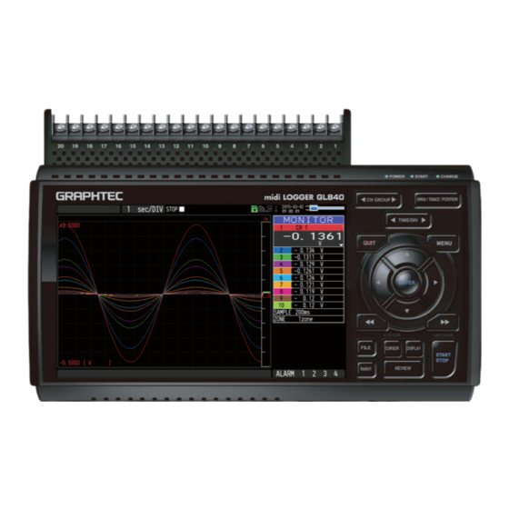
GRAPHTEC GL840 Quick Start Manual
Midi logger
Hide thumbs
Also See for GL840:
- User manual (208 pages) ,
- Quick start manual (24 pages) ,
- Quick start up manual (24 pages)

Related Manuals for GRAPHTEC GL840


Summary of Contents for GRAPHTEC GL840
- Page 1 LOGGER GL840 Quick Start Guide 604849022 GL840-UM-852 1.800.561.8187 information@itm.com www. .com...
-
Page 2: Table Of Contents
Thank you for choosing Graphtec midi LOGGER GL840. The Quick Start Guide is to assist you with basic operations. Please refer to the USER’ S MANUAL (PDF) in the CD-ROM for more in-depth information. Check the exterior of the unit to ensure that there are no cracks, defects, or any other damages before use. -
Page 3: Nomenclature
Nomenclature Top Panel Analog signal input terminals Power jack for humidity sensor • Standard terminal (B-564) Humidity sensor • Withstand High Voltage high-precision terminal (Option: when using the B-530) (B-565) Wireless LAN connection terminal Wireless unit (Option: when using the B-568) SD CARD2 GND terminal Front Panel... -
Page 4: Connection Procedures
Use a flathead screwdriver to push the button above connector marked as "DC LINE" on the GL840. the GND terminal while connecting the ground cable to the GL840. Connect the other end of the cable to ground. Connect to the Analog Input Terminals CH1...........CH20. - Page 5 Ferrite core (Supplied) GL840 midi LOGGER complies with the EMC Directive the supplied ferrite core is attached to the USB cable. When connecting with the USB cable, the USB driver must be installed to the PC. For information about how to install, refer to the "USB Driver Installation Manual"...
-
Page 6: Safety Guide For Using Gl840
< Between Channel to GND (C) > • Maximum input voltage: 300Vp-p • Withstand voltage: 2300 VACrms at 1 minute Warm-up GL840 requires approximately 30 minutes warm-up time to deliver the optimum performance. Unused channels The analog input section can frequently have cases of impedance. - Page 7 Input terminals Ex 2 : Connect GL840's GND to measurement object's GND. Ex 3 : Operate GL840 with batteries (Option: two B-569 batteries). Ex 4 : In the AMP settings menu, set filter to any setting other than "OFF". Ex 5: Set the sampling interval which enables GL840’s digital filter (see table below).
-
Page 8: Descriptions Of The Control Panel Keys
POSITION Change the trace settings (set the waveform display to On or Off). TRACE * If the QUIT key is pushed when the GL840 is in the SPAN, TRACE, or POSITION mode, the display returns to MONITOR mode. . TIME/DIV Push the [TIME/DIV] key to change the time axis display range on the waveform screen. - Page 9 . QUIT (LOCAL) Push the [QUIT] key to cancel the settings and return to default status. When you cancel the connection on the application, the GL840 is automatically sent back to local mode. If local mode is not entered, push the[QUIT] key.
- Page 10 Push the [START/STOP] key to initiate start and stop of recording while the GL840 is in the Free Running status. If the key is pushed while turning the power to the GL840 on the unit will switch from the USB connection mode to USB DRIVE mode.
-
Page 11: Descriptions Of The Menu Screens
When setting to the GL840 is displayed. base unit, the number of child units (wireless sensor) which are connects to the GL840 are displayed.) Wireless sensor unregistration display Remote lamp : Displays the remote status. (Yellow =... -
Page 12: Measurement Procedure
Quick settings : Displays items that can be easily set. The keys can be used to activate make a Quick settings item, and the keys to change the values. Alarm display area : Displays the status of the alarm output. (Red = alarm generated, white = alarm not generated) Pen display : Displays the signal positions, trigger... -
Page 13: Setup : Menu Operation
2. Setup : Menu Operation Select the setting for only the channels being used. Make sure to turn off unused channels. It is unnecessary to change all setting from the factory default. Key Pointers Basic Setup Menu Operation , [ENTER], and [QUIT] keys are used to set the condition on the setup menu. The current position of the cursor on the setup menu is displayed in green. - Page 14 4. Push the [MENU] key and open the "DATA" menu. Push the [MENU] key. Next, move the cursor to the “DATA” in the "MENU" at the top. 5. Set the sampling interval to "1s". Move the cursor to "Sampling" and then select "1s". 6.
- Page 15 (4) Go to the "SD1" level using the key. Move the cursor to the "Create New Folder" icon using the keys and then push the [ENTER] key. The Input menu will be displayed. (5) A text input box will be displayed. Create a folder named "TEST". (1) In the text type select;...
-
Page 16: Data Record : How To Record
Push the [START/STOP] key to end the data recording. (1) Push the [START/STOP] key. (2) Confirmation message is displayed. Push the [ENTER] key. (3) Recording ends, and the GL840 goes into the Free Running mode. The operation of data recording is complete. 1.800.561.8187 information@itm.com... -
Page 17: Data Replay : How To Replay Recorded Data
Push the [QUIT] key to end the data replay operation. A confirmation message is displayed. Push the [ENTER] key. Data replay ends, and the GL840 goes into the Free Running mode. GL840 has many additional features. Please refer to the following pages for details. 1.800.561.8187 information@itm.com www. -
Page 18: Additional Features
Additional features The GL840 has various functions that enhances and allows data to be collected and displayed more effectively. The following three functions describes these details. Trigger Functions to Control Recording Start/Stop Operations 1. Starting data capture Trigger functions control the timing of the start of a recording, and the timing of the end of a recording. - Page 19 GL840 to the Free Running status. (8) Push the [START/STOP] key to start recording. If the trigger condition has not been satisfied, the GL840 goes into the "Armed" status as shown on the following screen. When the trigger condition is satisfied, the recording starts. The display is changed to the “Data capture SD card 1”...
-
Page 20: Span, Trace And Position Functions To Adjust The Waveform Display
Key Pointers The span, trace and position operations can be performed while the GL840 is in the Free Running mode, while it is recording data, and while it is replaying data. The changes are applied to the displayed data only, and this change dose not affect the recorded data. -
Page 21: Specifications
Specifications Standard Specifications Item Description Number of analog channel GL840-M or GL840-WV (20ch per 1 terminal or maximum 200ch available with extension unit) External input and Trigger input and External sampling (1ch), Logic input (4ch) or Pulse input (4ch), Alarm output (4ch) -
Page 22: Common Specification Of The Terminal In The Input Section
Common specification of the terminal in the input section * The following specifications are common to GL840-M and GL840-WV. Item Description Number of input channels M3 screw type, 20 channels (maximum 200 channels with extension unit) Method Photo MOS relay scanning system, all channels isolated, balanced input... -
Page 23: Specification Of Input Section
Between input terminal/input terminal : 1 minute at 600Vp-p Between input terminal/GND : 2300 VACrms 1 minute Installation Guide For the installation procedure of the GL840 application software (USB driver / GL100_240_840-APS), refer to the “Application Software Manual” included in the attached CD-ROM.
Need help?
Do you have a question about the GL840 and is the answer not in the manual?
Questions and answers