Table of Contents
Advertisement
Quick Links
Advertisement
Chapters
Table of Contents

Related Manuals for Ricoh A109


Summary of Contents for Ricoh A109
- Page 1 A109 SERVICE MANUAL PN: RCSM5006 RICOH GROUP COMPANIES...
- Page 2 RICOH GROUP COMPANIES...
- Page 4 A109 FIELD SERVICE MANUAL PN: RCFM5006...
- Page 6 It is the reader's responsibility when discussing the information contained within this document to maintain a level of confidentiality that is in the best interest of Ricoh Corporation and its member companies. NO PART OF THIS DOCUMENT MAY BE REPRODUCED IN ANY FASHION AND DISTRIBUTED WITHOUT THE PRIOR PERMISSION OF RICOH CORPORATION.
- Page 8 The Field Service Manual contains information regarding service techniques, procedures, processes and spare parts of office equipment distributed by Ricoh Corporation. Users of this manual should be either service trained or certified by successfully completing a Ricoh Technical Training Program.
- Page 9 LEGEND PRODUCT CODE COMPANY GESTETNER RICOH SAVIN A109 NC5006 SC106 DOCUMENTATION HISTORY REV. NO. DATE COMMENTS 4/94 Original Printing 7/94 Revised Pages 6/96 Reprint 9/98 Reprint...
-
Page 10: Table Of Contents
2.3 COPIER INSTALLATION PROCEDURE ........3-6 2.4 PAPER SIZE CHANGE ..............3-23 2.5 OPTIONAL HOLDER (A702) INSTALLATION ......3-25 2.6 KEY COUNTER INSTALLATION ..........3-27 2.7 UPPER AND LOWER HEATER INSTALLATION (OPTIONS)............3-28 4. SERVICE TABLES 1. SERVICE REMARKS ............4-1 1.1 GENERAL CAUTION..............4-1 A109... - Page 11 2.1.7 To Clear The Counter ................4-10 2.2 SERVICE PROGRAM MODE TABLE ........4-11 2.2.1 Sp Adjustment..................4-11 2.2.2 SP Test Mode ..................4-17 2.2.3 SP Data Output..................4-21 2.2.4 Special Features ..................4-23 2.2.5 Jam/SC Counter ..................4-29 2.2.6 Operation Counter ...................4-30 2.2.7 Counter Clear...................4-32 A109...
- Page 12 5.1 PM TABLE ..................4-47 5.REPLACEMENT & ADJUSTMENT 1. COLOR BALANCE ADJUSTMENT ........5-1 2. COPY IMAGE ADJUSTMENT -PRINTING/SCANNING............5-5 2.1 PRINTING ...................5-5 2.1.1 Registration And Adjustment ..............5-7 2.1.2 Blank Margin Adjustment .................5-8 2.2 SCANNING ................5-10 3. EXTERIOR AND INNER COVERS ........5-12 A109...
- Page 13 LENGTH SENSOR (2) REPLACEMENT ........5-23 4.8 SCANNER MOTOR REPLACEMENT ........5-24 4.9 SCANNER DRIVE BELT REPLACEMENT ........5-26 4.10 SCANNER HOME POSITION SENSOR/SCANNER MOTOR DRIVE BOARD/LAMP REGULATOR BOARD/SCANNER UNIT LIFT SENSOR REPLACEMENT ...............5-27 4.11 SCANNER WIRE REPLACEMENT .........5-28 5. LASER UNIT ..............5-33 5.1 WARNING...................5-33 A109...
- Page 14 7.1 DRUM UNIT REMOVAL AND OPC DRUM REPLACEMENT ...............5-53 7.2 INSTALLING A NEW DRUM ............5-57 7.3 CLEANING BLADE REPLACEMENT.........5-60 7.4 CLEANING BRUSH REPLACEMENT ........5-61 7.5 BIAS ROLLER BLADE REPLACEMENT ........5-62 7.6 CHARGE WIRE REPLACEMENT ..........5-63 7.7 PRE-CLEANING CORONA WIRE REPLACEMENT .................5-64 A109...
- Page 15 11. TRANSFER BELT CLEANING UNIT ......5-89 11.1 TRANSFER BELT CLEANING BLADE REPLACEMENT ...............5-89 11.2 CLEANING BLADE SOLENOID REPLACEMENT ....5-90 11.3 TRANSFER BELT CLEANING ENTRANCE SEAL SOLENOID REPLACEMENT ...........5-91 12. LUBRICANT UNIT............5-92 12.1 LUBRICANT BRUSH AND LUBRICANT BAR REPLACEMENT ...............5-92 A109...
- Page 16 CHARGE INLET FAN, FUSING EXHAUST OZONE, OPTICSCOOLING FAN AND INNER COOLING FAN)............5-109 14.4 TONER TANK AGITATOR REPLACEMENT ......5-110 14.5 PAPER TRANSPORT BELT REPLACEMENT ......5-111 14.6 POINT ACCURACY ADJUSTMENT........5-112 6. TROUBLESHOOTING 1. SERVICE CALL CONDITIONS........... 6-1 1.1 SUMMARY..................6-1 1.2 SCANNING ...................6-3 1.3 PRINTING ..................6-6 A109...
- Page 17 3. ELECTRICAL COMPONENT DESCRIPTION....7-4 4. INSTALLATION..............7-6 4.1 ACCESSORY CHECK ..............7-6 4.2 INSTALLATION PROCEDURE ...........7-7 5. SERVICE TABLES............7-12 5.1 DIP SWITCHES AND SWITCHES ..........7-12 5.2 VARIABLE RESISTORS.............7-13 5.3 LEDs ...................7-13 5.4 FUSEs..................7-13 6. REPLACEMENTS AND ADJUSTMENTS ......7-14 A109 viii...
- Page 18 1.2.2 Electrical Components ................8-3 1.3 ELECTRICAL COMPONENT DESCRIPTIONS ......8-4 1.4 DRIVE LAYOUT................8-5 2. INSTALLATION..............8-6 2.1 ACCESSORY CHECK ..............8-6 2.2 INSTALLATION PROCEDURE ............8-7 3. SERVICE TABLES............8-13 3.1 TEST POINT ................8-13 3.2 LEDs ...................8-13 3.3 DIP SWITCH ................8-13 3.4 VARIABLE RESISTORS.............8-13 A109...
- Page 19 2.1 ACCESSORY CHECK ..............9-2 2.2 INSTALLATION PROCEDURE ............9-3 10. FILM PROJECTOR UNIT 1. SPECIFICATION ............... 10-1 2. ELECTRICAL COMPONENT LAYOUT AND DESCRIPTIONS..............10-2 3. INSTALLATION..............10-3 3.1 ACCESSORY CHECK ..............10-3 3.2 INSTALLATION PROCEDURE ..........10-4 CONTROLLER INTERFACE KIT TYPE-A BULLETINS A109...
-
Page 20: Important Safety Notices
Replace the battery only with an identical one. The manufacturer recommends replacing the entire RAM board. Do not recharge or burn this battery. Used batteries must be handled in accordance with local regulations. 1993 By Ricoh Company Ltd. All rights reserved A109... -
Page 21: Laser Safety
WARNING FOR LASER UNIT WARNING: Turn off the main switch before attempting any of the procedures in the Laser Unit section. Laser beams can seriously damage your eyes. CAUTION MARKING: A109... - Page 22 Replace the battery only with an identical one. The manufacturer recommends replacing the entire RAM board. Do not recharge or burn this battery. Used batteries must be handled in accordance with local regulations. A109...
-
Page 24: Specifications
A109 TAB INDEX SPECIFICATIONS DISPLAY EDITOR RE8 A997 COMPONENT LAYOUT AND DESCRIPTION FILM PROJECTOR UNIT A998 INSTALLATION CONTROLLER INTERFACE KIT TYPE-A SERVICE TABLES REPLACEMENT AND ADJUSTMENT TROUBLESHOOTING DUAL JOB FEEDER A376 SORTER A511... -
Page 26: Specifications
SPECIFICATIONS... - Page 28 A4, B5, A5, B6, " x 11" (LT) " x 11" " x 8 " (HLT) Odd paper Horizontal direction: 148 – 432 mm or 5.8" – 17.0" size Vertical direction: 100 – 297 mm or 3.9" – 11.7" A109...
- Page 29 1 minute standard setting; can also be set to 10 to 900 seconds in 1 second steps, or to no auto reset. Paper Feed: Paper Tray x 3 (500 sheets each) Bypass Feed Tray (50 sheets with paper lighter than 104.7g/m or 28 lb) A109...
- Page 30 692 x 685 x 1026 mm or 27.3" x 27.0" x 40.4" • Full System*: 1524 x 685 x 1099 mm or 60.0" x 27.0" x 43.2" (*= Copier + Dual Job Feeder + Sorter + Display Editor + Holder) • Copier Only: 200 kg or 440.8 lb Weight: A109...
- Page 31 • Dual Job Feeder Optional Equipment: • Sorter • Sorter Adapter • Projector Unit • Display Editor • Holder for Projector Unit/Display Editor • Key Counter A109...
-
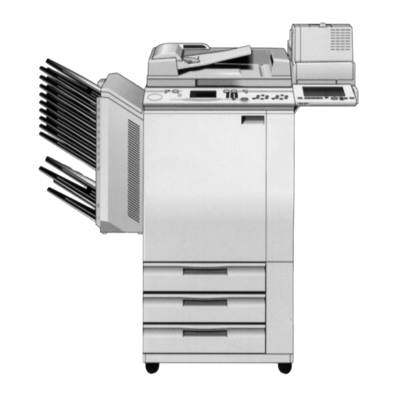
Page 32: Component Layout & Descriptions
COMPONENT LAYOUT AND DESCRIPTION... -
Page 34: Mechanical Component Layout
1. MECHANICAL COMPONENT LAYOUT A109... - Page 35 13. Paper Discharge Plate 31. Drum Cleaning Blade 14. Transport Belt 32. Cleaning Brush 15. Magenta/Yellow Development 33. Lens Unit 34. f-theta Lenses 16. 3rd Paper Tray 35. CCD Board 17. 2nd Paper Tray 36. Polygon Mirror 18. 1st Paper Tray A109...
-
Page 36: Drive Layout
2. DRIVE LAYOUT A109... - Page 37 23. By-pass Feed Drive Gear 10. Color-Development Drive Gear 24. Transfer Belt Drive Pully 11. Transport Unit Drive Gear 25. Transfer Belt Motor 12. Fusing Unit Drive Gear 26. Lubricant Brush Clutch 13. Transport Motor 27. Cleaning Motor 14. Tray Lift Motors A109...
-
Page 38: Air Flow
2. Fusing Exhaust Fan 8. DC Power Supply Cooling Fan 3. LD Cooling Fan 9. Inner Cooling Fan 4. Optics Exhaust Fan 10. Development Exhaust Fans 5. IPU Cooling Fan 11. Optics Cooling Fans 6. Polygon Motor Cooling Fan A109... -
Page 39: Electrical Component Descriptions
PCB13 Paper feed interface Interfaces the input/output of electrical components in the paper supply unit with the main control board. PCB14 Noise filter Removes electrical noise. PCB15 ID sensor Detects the density of the ID sensor pattern. A109... - Page 40 C - Sleeve Turns the C - sleeve roller in both directions. M - Sleeve Turns the M - sleeve roller in both directions. Y - Sleeve Turns the Y - sleeve roller in both directions. Drum Turns the OPC drum. A109...
- Page 41 FM 4 IPU cooling Provides air flow around the IPU board. FM 5 Polygon motor Provides air flow around the cooling polygon motor. FM6/7 Transport Sucks in air to attract copy paper 51/50 on the transport belts. A109...
- Page 42 C - development unit. Transport Detects misfeeds. Registration Detects the lead edge or trailing edge of copy paper to control the rotation of the paper feed and registration rollers. Registration guide Detects if the registration guide plate is set or not. A109...
- Page 43 3rd pick-up solenoid off timing. Original length - 1 Detects original length. Original length - 2 Detects original length. Original width Detects original width. Scanner unit lift Detects if the scanner unit is lifted or not. A109 2-10...
- Page 44 By-pass feed Starts paper feed from the by-pass feed table. Registration Drives the registration rollers. Transfer roller Controls the touch and release position operation of the transfer roller unit by using the transport motor’s drive. 2-11 A109...
- Page 45 2nd feed station. SOL10 3rd separation roller Controls the up/down movement of the separation roller in the 3rd feed station. Lamps Fusing Provides heat to the hot roller. Pressure roller Provides heat to the pressure roller. A109 2-12...
- Page 46 Thermofuses Fusing Opens the fusing lamp circuit if the fusing unit overheats. Pressure roller Opens the pressure roller lamp circuit if the fusing unit overheats. Thermoswitch Optics Opens the exposure lamp circuit if the 1st scanner overheats. 2-13 A109...
- Page 47 Cyan developments in both the single and full color copy modes. Others Circuit breaker Provides back-up high current protection for the electrical components. Main power relay Controls main power. Noise filter Removes electrical noise. Choke coil Removes high frequency current. A109 2-14...
-
Page 48: Installation
INSTALLATION... -
Page 50: Installation Requirements
Within 5 mm (0.2") of level 2. Right to left: Within 5 mm (0.2") of level NOTE: The machine legs may be screwed up or down in order to level the machine. Set a carpenter’s level on the exposure glass when you do this. A109... -
Page 51: Minimum Space Requirements
Place the copier near the power source, providing clearance as shown: Copier only Full system NOTE: A space of at least 10 cm (3.9") at the rear of the machine is necessary for smooth air inlet into the machine. A109... -
Page 52: Power Requirements
220 ∼ 240 V, 50/60 Hz: More than 7 A 2. Permissible voltage fluctuation: 10% 3. Do not set anything on the power cord. NOTE: a) Make sure the plug is firmly inserted in the outlet. b) Avoid multi-wiring. A109... -
Page 53: Copier Installation
2.1.2 Optional Table (Option: A702) 1. Base Bracket................... 1 2. Table Cover..................1 3. Front Cover ..................1 4. Lower Cover..................1 5. Philips Pan Head screws M4 x 6 ............ 9 6. Philips Truss Head screws M4 x 6..........2 A109... -
Page 54: Copier Separation
5. Lift-up the machine by using the handles. NOTE: a) When lifting the machine, lift straight up. Positioning pins [C] are located at the rear. b) When attaching, make sure to clear the harnesses out of the way. A109... -
Page 55: Copier Installation Procedure
(The leveling feet can be screwed up or down.) b) Keep the factory set data sheet under the operation panel for future use. We recommend making a copy to be kept at your office also. A109... - Page 56 1. Remove the tape strips. 2. Open the front doors then remove the tape strips [C] around the toner tank and two tapes [D] fixing the registration guide plates (B and B knobs). A109...
- Page 57 (red tag) securing the toner hopper to the frame. 5. Install the operating instruction holder [C] (two M4 x 8 truss screws). 6. Push and slide out the toner tank [D]. Then remove the toner tank [D] (2 screws). A109...
- Page 58 8. Remove the yellow toner supply receptacle [C] (1 screw). 9. Disconnect the three connectors [D] and free them from the three harness clamps. 10. Remove the transfer belt stay [E] (5 screws). 11. Pull and remove the transfer belt cleaning unit [F] out. A109...
- Page 59 13. Remove the charge corona unit [D] (1 screw), PCC [E] (1 screw) and ID sensor board [F] (1 screw). 14. Remove the knob [G] and the two screws [H] and slightly (2 ∼ 3 cm) pull out all the development units then remove the drum stay [I]. A109 3-10...
- Page 60 [B]) and remove the black/cyan development unit [C] (1 release lever [D]). 16. Disconnect the drum’s toner collection pipe [E] as shown. 17. Remove the knob screw [F] (counterclockwise), and pull out the quenching lamp. 18. Remove the drum unit [G] (2 screws). 3-11 A109...
- Page 61 23. While pressing up the latch [E] to apply the cleaning blade pressure, rotate the OPC drum counterclockwise 3 times to ensure the setting powder is evenly applied, as shown. NOTE: Hold only the edge of the OPC drum to rotate it (within 1 cm from the end). A109 3-12...
- Page 62 4) Set the drum stay by securing the 2 screws [C] then the knob [D]. 5) Reinstall the charge corona unit [E], PCC [F], and the ID sensor board [G] (1 screw each). 3-13 A109...
- Page 63 26. Re-install the following units or parts in the following order. 1) Transfer belt unit. 2) Transfer belt cleaning unit 3) Transfer belt stay (5 screws) 4) Three connectors (6P white, 3P red, 3P white) 5) Toner collection duct (1 hook) A109 3-14...
- Page 64 28. Open the exit unit [C] (2 "D4" release levers). 29. Loosen the 2 black screws [D] until it moves freely so that the fusing pressure is being applied. NOTE: Do not turn the pressure adjustment screws which are located just beside the screws [D]. 3-15 A109...
- Page 65 Note: This step is not necessary for U.S. market. 1) Remove the operation panel [H] (4 screws and 2 connectors). 2) Install the requested language roms [I]. 3) Reinstall the operation panel making sure that the panel is properly hooked in [J]. A109 3-16...
- Page 66 3) Press the clear/stop keys for more than 3 seconds. 39. Touch the SP Test Mode key [A]. 40. Touch the Next key [B] to open page 7. NOTE: Wait until the development unit drive stops then start the step 3-17 A109...
- Page 67 [H]. NOTE: Do not touch the stop key within 1 minute, otherwise, the developer will not be evenly distributed in the development unit. 49. Remove the developer supply funnel, then install the toner supply receptacle. A109 3-18...
- Page 68 57. Confirm V has the same values as Vref for all colors (Bk, Y, M, C). If not, touch the Index key [F] then return to the test mode page 5 to perform the developer initial setting (step 53) again. 3-19 A109...
- Page 69 63. Place the C-4 test chart on the exposure glass. 64. Touch the Copy In SP key [D] and make 30 full color copies using A3 or 11" x 17" size paper. (60 full color copies using A4 or 11" x 8 " is also acceptable.) A109 3-20...
- Page 70 69. Touch the Next key [C] to open page 2. 70. Confirm that the PID key [D] is selected for the Process Control Mode Selection. If not, touch the PID key [D]. 71. Touch the Index key [E]. 3-21 A109...
- Page 71 81. Turn off the main switch and return the switch actuator to it’s original position. 82. Reinstall the right inner cover (3 screws) and turn on the main switch. 83. Check the copy quality and adjust if necessary. (Refer to section 5.) A109 3-22...
-
Page 72: Paper Size Change
1. Draw out the paper feed tray [A]. 2. Change the position of the front and the rear side fences [B] (1 screw each) and the end fence [C] (1 screw) according to the paper size. 3-23 A109... - Page 73 2nd or the 3rd feed station. 6. Touch the Index key [C]. 7. Touch the Exit key [D] to exit SP mode. 8. Check copy quality and machine operation. A109 3-24...
-
Page 74: Optional Holder (A702) Installation
2.5 OPTIONAL HOLDER (A702) INSTALLATION 1. Remove the right upper cover [A] (2 screws). 2. Install the holder base bracket [B] (6 screws). 3. Install the holder cover [C] (2 screws). 3-25 A109... - Page 75 5. Install the front cover [B] (1 screws). 6. Install the top cover [C]. NOTE: a) If installing the display editor, step 5 is not necessary. b) If installing the film projector unit, step 6 is not necessary. A109 3-26...
-
Page 76: Key Counter Installation
(2 screws). NOTE: The fixing plate has three different hole sizes. Use the holes that match those on the key counter holder that you are installing. 7. Reinstall all the covers and check the key counter operation. 3-27 A109... -
Page 77: Upper And Lower Heater Installation (Options)
4. Mount the harness to the clamp [C] and connect as shown. 5. Install the lower tray heater assembly [D] (2 M4 x 8 screws). 6. Mount the harness to the clamp [E] and connect as shown. 7. Reinstall the paper feed trays [A]. A109 3-28... -
Page 78: Service Tables
SERVICE TABLES... -
Page 80: Service Remarks
9. Before pulling out the drum unit, place a sheet of paper under the drum to catch any spilt toner. 10. Dispose of used drums according to local regulations. 11. When removing the drum from the drum unit, release the pressure of the drum cleaning blade by moving the knob. A109... -
Page 81: Transfer Belt Unit
4. Take care not to scratch the transfer belt as the surface is easily damaged. 5. Before installing the new transfer belt, clean all the rollers and shafts with alcohol to prevent belt slipping. A109... -
Page 82: Scanner Unit
2. Do not turn the volume on the LD unit as they are adjusted in the factory. 3. The polygon mirror and Fθ lenses are very sensitive to dust. Never open the optical housing unit. 4. Do not touch the polygon mirror’s reflecting surface with bare hands. A109... -
Page 83: Charge Corona
6. When removing or installing the development unit, be careful not to damage the drum surface by the entrance seal on the development unit. 7. Never load different types of developer and toner into the development unit. Doing so will cause poor copy image and toner scattering. A109... -
Page 84: Drum Cleaning
2. Do not touch the cleaning brush with oily bare hands. 3. Clean the PCC wire with dry cloth. Do not use sandpaper or a solvent. 4. Clean the PCC casing with damp or dry cloth. 5. Clean the PCC end blocks with dry cloth. A109... -
Page 85: Transfer Belt Cleaning
8. After replacing the oil blade and oil supply pad, prime the entire length of the blade with silicon oil. 9. Do not touch the screws for the pressure springs. These are adjusted at the factory to maintain the proper nip band width. A109... -
Page 86: Paper Feed
2. When reinstalling the used toner tank, make sure that the toner overflow sensor connector is inserted firmly. 3. Dispose of used toner according to local regulations. Never throw into an open flame, for toner dust may ignite when exposed to open flame. A109... -
Page 87: Service Program Mode
Only 5 service program modes are visible on the touch panel display at one time. Use the down key [B] or the up key [C] to see other service program mode menus. 2.1.2 To Exit SP Mode Exit 1. Touch the key [D]. A109... -
Page 88: To Return To The Index Menu
2.1.5 Access to "Copy in SP" Mode Copy in SP 1. Touch [D] to access "Copy in SP" mode. LCD displays as shown at right. 2. Select the appropriate copy mode and make trial copies. 3. Return to the SP mode by pressing [E]. A109... -
Page 89: To Input Data
NOTE: If you forget to touch the enter key, the previous data remains. 2.1.7 To Clear The Counter 1. Touch the clear key [D]. 2. If you are sure to clear, touch the [E] . If you want to cancel to clear, touch [F]. 4-10 A109... -
Page 90: Service Program Mode Table
OHP/thick paper mode. Adjustable range: –9.9 ∼ 9.9 mm (0.1 mm/step) Adjustable range: –9.9 ∼ 9.9 mm Adjust the horizontal image position by changing the main scanning start position for each paper feed section. (0.1 mm/step) A109 4-11... - Page 91 OHP/Thick full color mode: 160°C Adjustable range: 100°C ∼ 200°C paper mode Factory use only Default: 0 Do not change the data in the field Factory use only Default: 0 Do not change the data in the field 4-12 A109...
- Page 92 Adjustable range: 500 ∼ 4000 V Adjusts the transfer roller bias voltage for each transfer process 1C ∼ 4C and Default: Normal Thick paper modes (Normal, OHP, Thick). 1325 1515 2095 1515 1710 2530 1660 1230 2045 1230 A109 4-13...
- Page 93 Manually change the target voltage of Default: 2.5V (Bk, Y, M, C) Adjustable range: 0 ∼ 5.0 V the TD sensor output (V ) during the developer initial setting. Do not change the data in the field. 4-14 A109...
- Page 94 AGC. Do not change the data in the field. Selects the AD-V coefficient so that Default data: Copier 110 white shading data won’t overflow. SPU: ??? Do not change the data in the field. A109 4-15...
- Page 95 Do not change the data in the field. Adjust the scanner motor speed by Motor current adjustment changing the scanner motor input Default: 100 current Fine adjustment Default: 0 Do not change the data in the field. 4-16 A109...
-
Page 96: Sp Test Mode
(#202) are enabled, only the gradation pattern is printed. Selects the kind of test patterns. Access the Copy in SP and press the start key to print the test pattern. Factory use only Do not use in the field. A109 4-17... - Page 97 OPC drum/developer/RAM etc. This mode should be performed with a drum not used for more than 5 minutes. This mode automatically stops after completing. Starts and stops the drum potential This mode automatically stops after sensor calibration. completing. 4-18 A109...
- Page 98 Starts each free run mode. Paper is not fed in free run modes. When using the system free run, close the platen cover or place white sheets of paper on the exposure glass to avoid toner scattering inside the machine. A109 4-19...
- Page 99 Factory use only sequence Turn on the exposure lamp. Factory use only Use to check if the original size sensors Status 0 --- de-activated are correctly activated or de-activated at Status 1 --- activated the 1st and 2nd detection. 4-20 A109...
-
Page 100: Sp Data Output
ID sensor for each color and potential sensor output while detecting Id sensor pattern. Indicate the target and actual data VD: charge potential relate to process control. VL: exposed drum potential VB: development bias γ: development gamma VK: development reference data 4-21 A109... - Page 101 Item Function Note Displays DA1 settings. Factory use only Displays DA2 settings. Factory use only Displays DA2* settings. Factory use only Displays DA3 settings. Factory use only A109 4-22...
-
Page 102: Special Features
11.3 g/m ) x (B%) (A%) (B%) 2C ∼ 4C Default output 1C ∼ 4C (Output for less Output for 4.3 ∼ Transfer (Output for more roller than 4.3 g/m than 11.3 g/m3) x 11.3 g/m bias (C%) (D%) 4-23 A109... - Page 103 (No choice other than fuzzy for this mode.) Factory use only Do not change the STEP data in the field Adjusts image density for each color in See section 5, color balance letter mode. (Letter mode rough adjustment. adjustment.) A109 4-24...
- Page 104 Adjusts each color image density (Photo Do not change the data in the field mode fine adjustment) Indicates the correction data decided in Indication only auto γ correction Enable or disable the auto γ correction Default: ON mode. 4-25 A109...
- Page 105 Selects the default feed station Default: Auto Paper Selection Enables ADS mode selection as a Default: ON default mode Selects the default original mode Default: Auto Enables the display editor operation. Default: No When the display editor is installed, select "Display". A109 4-26...
- Page 106 IC127/128 and IC134 on the scanner control board Reference number for the combination of IC303 and IC309 on the IPU board Operation Panel: IC101 Transfer Belt: Transfer belt motor drive IC609 Editor: Reference number of editor ROM 4-27 A109...
- Page 107 Selects the PM alarm interval after If you do not use PM alarm, set "0". counter clear. Default: 0 Selects the paper size and direction of Refer to section 3 for details of paper size each paper feed station. change procedure. A109 4-28...
-
Page 108: Jam/Sc Counter
Press to scroll down. Indicates the total number of jams in the copier and all peripherals. Indicates the total number of jams at each location. Indicates the total number of jams in the DJF. 4-29 A109... -
Page 109: Operation Counter
Indicates the total number of copies broken down by the original modes. Indicates the total number of scans since the last PM for each color developer. Indicates the total number of copies broken down by the paper size. Indicates the total operation time. A109 4-30... - Page 110 Item Function Note Indicates the total number of copies broken down by the copy modes. 4-31 A109...
-
Page 111: Counter Clear
2. The display asks Yes or No, if you Clears all jam and SC counters are sure to clear, touch Yes, if you do not want to clear, touch No. Clears all jam counters Clears all SC counters A109 4-32... -
Page 112: Sensor/Switch/Signal Data Check (Inputmode)
[B] on the display six times. Input No. 000 4. 1) Touch [C]. 2) Enter the input sensor/switch/signal number by using the number keys (Refer to the table in the following pages). 3) Press the Enter key [D]. 4-33 A109... -
Page 113: Input Check Mode Table
Paper not detected detected 2nd paper end sensor Paper Paper not detected detected 3rd paper end sensor Paper Paper not detected detected Transfer belt position sensor Release Touch Transfer roller position sensor Release Touch 1st lift sensor Not lifted Lifted A109 4-34... - Page 114 Grounded Not grounded (High) (Low) By-pass paper size-4 Grounded Not grounded (High) (Low) 2nd tray set switch Not set 3rd tray set switch Not set By-pass length sensor Paper not Paper detected detected Sorter connection detection Connected connected 4-35 A109...
-
Page 115: Electrical Component Check (Output Mode)
– How to check the sensor/switch/signal – 1. Enter SP mode as follows: 1) Press the mode clear key. 2) Enter "107". 3) Press the clear/stop key for more than 3 seconds. 2. Touch [A] on the display to access SP Test mode. A109 4-36... - Page 116 [D] to activate Stop and press [E] to de-activate the electrical component. Stop NOTE: If you select and start another output mode without touching, the two output modes function simultaneously. After completing, stop all test modes now functioning. 4-37 A109...
-
Page 117: Output Check Mode Table
Drum motor - Forward Drum motor - Reverse Cleaning motor Polygon motor Bk-Sleeve motor - Forward Bk-Sleeve motor - Reverse Y-Sleeve motor - Forward Y-Sleeve motor - Reverse M-Sleeve motor - Forward M-Sleeve motor - Reverse C-Sleeve motor - Forward A109 4-38... - Page 118 1st separation roller solenoid 2nd separation roller solenoid 3rd separation roller solenoid Fusing heater - Hot roller Fusing heater - Pressure roller Anti-condensation heater relay (on noise filter board) Potential sensor calibration relay (on H.V.S. Board - B) Main power relay 4-39 A109...
- Page 119 Transfer roller position clutch Registration clutch By-pass feed clutch 1st Feed clutch 2nd Feed clutch 3rd Feed clutch Lubricant brush position clutch Not used Quenching lamp Cleaning entrance seal solenoid - Touch Cleaning entrance seal solenoid - Release A109 4-40...
-
Page 120: Sp Modes After Replacement And Cleaning
30 copies with the toner tank • • • • • 2-6, 210 Process Control Self Check ° NOTE2 • 2-6, 208 Belt Cleaning Mode 4-3 ∼ 6, • • • • • • Color Balance Adjustment 405, 406 ° 4-41 A109... -
Page 121: Memory All Clear Procedure
7. Check copy quality and paper path and do the necessary adjustments. 8. When the "Memory All Clear" procedure does not succeed, replace the RAM board and contact your service key person for special steps to be followed. A109 4-42... -
Page 122: User Tools Menu
Use these keys to see other user tools. Use to exit from the user tool menu. Use to return to the user tool menu. • Refer to the operating instructions for the contents and functions of user tools. 4-43 A109... -
Page 123: User Tools Access Procedure 2
No. 7, 8, 9, 10, and 11 for the user code mode. 1. Press the Clear Modes/Stand by key. 2. Enter "993". 3. Press the Clear/Stop key more than 3 seconds until the User Tool Menu appears on the touch panel display. A109 4-44... -
Page 124: Test Points / Dip Switches / Led's
4.1.3 LED LED 502: It turns ON and OFF by counting the program loops run by the main CPU. If the machine does not become ready with keeping this LED OFF, the main control board might be defective. 4-45 A109... -
Page 125: Ipu Board
LED300 ∼ 307: IPU-CPU monitor If all the LED’s blink together, the Main-CPU and the IPU-CPU have a communication error. → SC code appears. LED308: Laser synchronizing signal monitor LED309: Monitor for the combination of SW300-3, 4, 5. A109 4-46... -
Page 126: Preventive Maintenance Schedule
PAPER FEED (Paper Supply Unit) Paper Guide Plate, Alcohol or water Vertical Transport Plate Pick-up Rollers Water Paper Feed Rollers Water Separation Rollers Water Vertical Transport Alcohol Rollers Vertical Transport Plate Alcohol or water Tray Bottom Plate Pad Alcohol or water 4-47 A109... - Page 127 Cleaning Brush Inspect if the brush functions properly. Bias Roller Blade Dust with setting powder after replacement or cleaning. Cleaning Bias Roller Dry cloth or Alcohol Dust with setting powder. Cleaning Side Seals, Dry Cloth Casing A109 4-48...
- Page 128 Remove the brush and clean with dry cloth. (NOTE 4) Lubricant Brush (NOTE 4) Entrance Seal FUSING UNIT Hot Roller (NOTE 5) Heat Isolating Bushing Barrierta L55/2 (NOTE 5) Hot Roller Ball Bearing Clean with dry cloth. (NOTE 5) 4-49 A109...
- Page 129 EM 48K 96K 144K 192K 240K NOTE DUAL JOB FEEDER (A376) (Number of Originals) Transport Belt Belt cleaner Replace if necessary. Pick-up Roller Alcohol Replace if necessary. Feed Roller Alcohol Replace if necessary. Separation Belts Alcohol Replace if necessary. A109 4-50...
- Page 130 CAUTION 2: When cleaning and drying the charge corona grid with cloth, be careful there is no fiber dust on the grid. 4-51 A109...
- Page 131 Development duct lower filter [H] NOTE 2: Transfer Belt Unit The following parts should be lubricated with Mobil Temp 78 grease every 40K scans: • Transfer belt release cams [I] • Belt bias roller shaft [J] (only at the end) A109 4-52...
- Page 132 The ball bearings [G] for the hot roller should be cleaned with dry cloth every 40K scans and should be replaced every 160K scans. The fusing drive gears [H, I] should be lubricated with Mobil Temp. 1 or 78 every 80K scans. 4-53 A109...
- Page 133 NOTE: 6 Fusing Unit 2 When replacing the pressure roller [A] and its ball bearings [B] every 160k scans, lubricate the roller shaft [C] and inner surface of the ball bearings with Barrierta L55/2. A109 4-54...
- Page 134 5. Dispose the toner inside the toner catch pan. 6. Replace the paper discharge plate. 7. Inspect the transfer roller. Replace if the surface is damaged. 8. Lubricate the transfer roller shaft. [Silicone Grease G40M] 4-55 A109...
- Page 135 1. Clean the charge corona wire, grid, (every 80 k) casing, and end blocks. 2. Clean the quenching lamp and ID Replace the PCC wire sensor. (every 80 k) 3. Clean the PCC wire, casing and end blocks. A109 4-56...
- Page 136 [Apply silicone oil on surface] 8. Clean the pressure roller thermistor. [Apply silicone oil on surface] 9. Clean the hot roller cleaning roller and scraper. [Use suitable solvent] 10. Inspect the amount of silicone oil in the tank. Add oil if necessary. 4-57 A109...
- Page 137 3. Clean the registration sensor with a blower brush. Clean the By-pass Feed Pad and Paper Feed Guide Plate with Alcohol or Water. (every 80 k) Replace the By-pass Pick-up, Paper Feed and Separation Roller (every 200 k) A109 4-58...
- Page 138 • Perform SP2-5, No. 207 (Toner Density Initial Setting) and other 13. Copy Quality procedures. NOTE: The process control self check will be performed whenever the machine is turned on while the hot roller temperature is below 100°C. 4-59 A109...
-
Page 140: Replacement & Adjustment
REPLACEMENT AND ADJUSTMENT... -
Page 142: Color Balance Adjustment
1. Select the 11" x 17" paper tray and make a full color copy using the C-4 test chart in letter mode [A]. 2. Enter the SP mode and open SP Special Feature P-3, No. 405 (γ Correction Data Rough Adj. "Letter") [B]. A109... - Page 143 ID’s to an acceptable shade of gray. 4. Touch the Copy in SP key [H] and select the photo mode [I]. 5. Using the 11" x 17" paper tray make a single color copy (black) and a full color copy using the C-4 test chart. A109...
- Page 144 (table on page 5-4 of the FSM) 8. Checking the copy image of the full color copy, adjust the "OFF SET" [L] settings for the Cyan, Magenta, and Yellow ID by refering to the following table (all steps) (Table on page 5-4 of the FSM). A109...
- Page 145 C-4 test color scale chart. Low ID [P] The levels should be an 1 2 3 4 5 6 7 8 9 of Y, M, C acceptable shade of grey. 3rd, 4 , and 5 level of the black scale A109...
-
Page 146: Copy Image Adjustment -Printing/Scanning
2 ± 2 (mm), 0.08" ± 0.08" B1 : 2 ± 2 (mm), 0.08" ± 0.08" No Standard 2 ± 2 (mm), 0.08" ± 0.08" 4 (mm), 0.16" or less 5 ± 2 (mm), 0.2" ± 0.08" 2 ± 2 (mm), 0.08" ± 0.08" A109... - Page 147 (causing the faulty copy image). (Example) • • - Original - Faulty Lead Edge Faulty Lead Edge Blank Margin Registration If the registration is within standard, go to step 11 and adjust the blank margin. A109...
-
Page 148: Registration And Adjustment
(Side to Side Registration "Printing") [I] and adjust the side-to-side registration to meet the standard copy image (A ) by changing the setting [J]. NOTE: Copy image will shift to the left when entering a greater setting. (0.1 mm/bit) A109... -
Page 149: Blank Margin Adjustment
Sub Scan Lead Edge, adjusts the blank margin at the leading edge of the copy paper. Sub Scan Trail Edge, adjusts the blank margin at the trailing edge of the copy paper. 17. Open SP Test Mode P-3, No. 205 [M] and touch the Reset key [Q]. A109... - Page 150 7,10 and 14. – By-pass Feed Table (OHP/Thick Paper) – 1. Perform the same procedures as the 3rd paper tray adjustments except in step 9, select the OHP/Thick Paper key [R], and in step 10, select the By-pass Feed [S]. A109...
-
Page 151: Scanning
SP Adjustment P-20, No. 130 (Vertical Line Alignment) [D]. Read the present setting and locate the setting on the graph (see next page). 6. Change the setting according to the graph on the next page by following these rules: A109 5-10... - Page 152 If both lines are visible, but the cyan line is further from the black line, choose a setting on the top line. • If both lines are visible, but the yellow line is further from the black line, choose a setting on the bottom line. Vertical alignment settings (Default=55) 5-11 A109...
-
Page 153: Exterior And Inner Covers
2. Remove the fusing gear release bracket [B] (1 screw). 3. Pull out the pin [C]. 4. Lift up and remove the front door [A]. NOTE: When re-installing, make sure that the gear release arm hole [D] meets the gear release bracket’s pin [E]. A109 5-12... -
Page 154: Upper Rear Cover
3.1.4 Lower Rear Cover 1. Remove the lower rear cover [D] (4 screws). 3.1.5 Lower Left Cover 1. Remove the lower rear cover [D]. 2. Pull out all paper trays. 3. Remove the lower left cover[E] (4 screws). 5-13 A109... -
Page 155: Right Front Door
2. Remove the upper rear cover. 3. Push open the by-pass feed table [B]. 4. Remove the upper right cover [C] (5 screws). 3.1.8 Lower Front Cover 1. Open both doors. 2. Remove the lower front cover [D] (1 screw). A109 5-14... -
Page 156: Top Cover
2. Remove the left original scale [A] (2 screws) and the rear scale [B] (3 screws). 3. Remove the top right cover [C] (2 screws). 4. Remove the operation panel [D]. (See Operation Panel Removal Section.) 5. Remove the top cover [E] (4 screws). 5-15 A109... -
Page 157: Inner Cover Removal
2. Remove the toner hopper unit. (See Development Unit Removal Section.) 3. Remove the lower left inner cover [C] (2 screws). 3.2.4 Upper Left Inner Cover 1. Remove the front door. 2. Remove the total counter cover [B]. 3. Remove the upper left inner cover [D] (2 screws). A109 5-16... -
Page 158: Scanner Unit
[D] by sliding it to the rear side as shown in the figure. NOTE: When reinstalling the exposure glass, make sure of the following: a) The white reference plate [E] must be facing down. b) Position the white plate at the left. 5-17 A109... -
Page 159: Exposure Lamp Replacement
[B]. (See illustration.) 4. Remove the reflector cover [C] (2 screws). 5. Remove the rear terminal assembly [D] (1 screw) and remove the exposure lamp [E] as illustrated. 6. Install a new lamp in the opposite way. A109 5-18... -
Page 160: Optics Thermoswitch Replacement
4. Remove the exposure lamp leads [C] from the terminals on both sides of the thermoswitch [D]. NOTE: Do not pull the harness. Pull off the lamp leads by using the connector housing. 5. Replace the thermoswitch [D] (2 screws). 5-19 A109... -
Page 161: Scanner Control Board Replacement
3. Remove the top right cover [A] (2 screws). 4. Remove the lens cover [B] (9 screws). 5. Disconnect all the connectors from the scanner control board [C]. 6. Replace the scanner control board [C] (4 screws, 1 fiber cable). A109 5-20... -
Page 162: Lens Unit (Ccd Board) Replacement
1. Perform steps 1 to 4 of the scanner control board replacement section. 2. Disconnect the 3 connectors from the CCD board [A]. 3. Free the ground wire [B] of the CCD board (1 screw). 4. Remove the lens unit [C] (4 screws). 5-21 A109... -
Page 163: Original Length Sensor (1) Replacement
4.6 ORIGINAL LENGTH SENSOR (1) REPLACEMENT 1. Perform steps 1 to 4 of the scanner control board replacement section. 2. Replace the original length sensor 1 [A] (1 screw, 1 connector). A109 5-22... -
Page 164: Original Width Sensor And Original Length Sensor (2) Replacement
1. Turn off the main switch and unplug the machine. 2. Remove the exposure glass. (See Exposure Glass Removal.) 3. Remove the APS sensor cover [A] (7 screws). 4. Replace the original width sensor [B] or the original length sensor (2) [C] (1 screw, 1 connector each). 5-23 A109... -
Page 165: Scanner Motor Replacement
4. Remove the platen cover position sensor [D] (1 screw and 1 connector). 5. Remove the left scale bracket [E] (2 M3 x 5 screws) and the right stay bracket [F] (4 screws). NOTE: Screws [G] are M3 x 5 screws. 6. Remove the rear frame [H] (15 screws). A109 5-24... - Page 166 Check the direction of the motor harness [E] when securing the motor [C] to the motor bracket [F]. c) The scanner motor belt runs over the pulley. d) Hook the spring first, then secure the motor to the frame. 5-25 A109...
-
Page 167: Scanner Drive Belt Replacement
5. Remove the CG power pack [D] (2 screws and 3 connectors). 6. Lift up the scanner unit. (See Optical Housing Unit Replacement Section.) 7. Remove the wire pulley under bracket [E] by unscrewing the 2 screws [F]. 8. Replace the scanner drive belt [G]. A109 5-26... -
Page 168: Board/Scanner Unit Lift Sensor Replacement
• Replace the lamp regulator board assembly [C] (2 screws and 3 connectors). -Scanner Unit Lift Sensor- • Remove the scanner unit lift sensor [D] with the bracket on (1 screw and 1 connector). • Replace the sensor. 5-27 A109... -
Page 169: Scanner Wire Replacement
6. Loosen the front and rear brackets [E] securing the wire to the 1st scanner as shown in the figure. 7. Loosen the bracket fixing screw [F] and the adjusting screws [G]. 8. Remove the tension spring [H] located at the left side and remove the scanner wires. A109 5-28... - Page 170 No gap between the pulley and the flat washer. b) The wire crossing face the front of the machine. 11. Secure the second scanner with the 2 pins [N,O] by using the holes located furthest to the left. 5-29 A109...
- Page 171 (1) the upper groove of WP1 through (2) the outer groove of WP8 over (2) the rear clamp CL 1 to (3) WP6 and (3) the inner groove of WP 8 to (4) the hook to tension spring [B]. (4) the anchor point AP1. A109 5-30...
- Page 172 17. Manually position the first scanner [P] to the position over its pin holes, and install the positioning pins [Q, R]. 18. Clamp the front and rear clamps [CL1, CL2] securing the wire to the first scanner (for now). 19. Remove the positioning pins [Q, R]. 5-31 A109...
- Page 173 [CL1, CL2]. 24. Manually move the 1st scanner [P] to the position over its pin holes and install the positioning pins [Q, R]. 25. Secure the clamps [CL1, CL2]. 26. Remove the positioning pins and reinstall the unit. A109 5-32...
-
Page 174: Laser Unit
WARNING: Turn off the main switch and unplug the machine before attempting any of the procedures in this section. Laser beams can seriously damage your eyes. – CAUTION DECAL – Five caution decals are located in the laser unit, as shown. 5-33 A109... -
Page 175: Optical Housing Unit Replacement
10. Open the harness clamps [H] and disconnect all the connectors on the IPU board. Remove the white plug (4 wires) from frame of machine. Make the IPU harnesses loose at the right rear corner so that the IPU board bracket can be raised freely. A109 5-34... - Page 176 13. Reassemble all the parts according to the above steps in reverse. NOTE: When fixing the optical housing unit, secure the three screws [F] without the wedge first. Insert the wedge [G] and secure the screw when the wedge is stopped lightly. 5-35 A109...
-
Page 177: Ld Unit And Polygon Motor Replacement
(front view). – Polygon motor – 3. Remove the polygon motor [C] from the optical housing unit (2 screws). NOTE: When replacing the polygon motor, make sure that the connector is located at the front. A109 5-36... -
Page 178: Laser Synchronizing Detector Board Replacement
If LED308 keeps a strong intensity, turn off the main switch and unplug the machine. Then adjust the position of the laser synchronizing detector board by using the upper holes. 7. Turn off the main switch and unplug the machine. Then reassemble the machine. 5-37 A109... -
Page 179: Polygon Motor Drive Board Replacement
1. Open the scanner unit and hang the IPU board bracket underneath the scanner unit. (Follow steps 1 to 11 of the optical housing unit replacement procedure.) 2. Replace the polygon motor drive board [A] (2 screws, 2 connectors). A109 5-38... -
Page 180: Paper Feed Section
1. Turn off the main switch and unplug the machine. 2. Remove the 3 paper trays [A] (4 screws each). 3. Replace the pick-up roller [B], the paper feed roller [C] and the separation roller [D] from each paper feed station (1 snap-ring each). 5-39 A109... -
Page 181: Paper Feed Clutch, Pick-Up And Separation Roller Solenoid Replacement (1St, 2Nd And 3Rd Feed Unit)
7. Disconnect the 2P connector (orange wires) from the intermediate connector. Release wires from clamps. 8. Remove the vertical guide plate [F] (2 screws) by sliding to the left. NOTE: Disconnect wires & release all the harness from clamps when removing the vertical guide plate. A109 5-40... - Page 182 Before removing 1st feed unit, 2nd feed unit must be removed. • While supporting the 1st paper feed unit [C], remove the bracket [D] (3 screws). • Remove the 1st paper feed unit [C] by sliding it to the left. 5-41 A109...
- Page 183 –2nd Feed Unit– • Disconnect the connectors [A]. • Remove the 2nd paper feed unit [B] (2 screws) by sliding it to the left. A109 5-42...
- Page 184 [F] then fully push in the clutch on the feed roller shaft [G] and secure the Allen screw. NOTE: When re-installing the paper feed units, install the 1st paper feed unit before installing the 2nd paper feed unit. 5-43 A109...
-
Page 185: Paper Feed Motor Replacement
6. Remove the paper feed motor unit [E] (3 screws and 1 connector). 7. Remove the motor pulley [F] (1 Allen screw). 8. Replace the paper feed motor (3 screws). NOTE: When reinstalling, make sure that the motor shaft and the pulley are aligned. A109 5-44... -
Page 186: Tray Lift Motor (1St, 2Nd, And 3Rd) Replacement
Free the harness from the clamps and replace the motor [A] (1 screw, 1 connector). –2nd Tray Lift Motor– • Remove the Paper Feed Motor Unit. (See Paper Lift Motor Replacement Section.) • Free the harness from the clamp and replace the motor [A] (1 screws and 1 connector). 5-45 A109... -
Page 187: By-Pass Feed Table
8. Remove the 2 step screws [I] securing the by-pass feed table. 9. Pull out the by-pass feed table by gently pressing down on the by-pass feed table until both of the tables pins meet the stay’s openings as illustrated [J]. 10. Replace the separation roller [K] (1 snap-ring). A109 5-46... -
Page 188: By-Pass Paper Width Sensor And By-Pass Paper Length Sensor Replacement
2. Open the by-pass feed table [A] and extend the paper supporting lever [B]. 3. Remove the by-pass feed table outer cover [C] (2 screws). 4. Close the by-pass feed table. 5. Replace the width sensor [D] (2nd screws and 1 connector) or the length sensor [E] (1 connector). 5-47 A109... -
Page 189: By-Pass Feed Clutch And By-Pass Pick-Up Solenoid
2. Remove the by-pass feed table. (See Pick-up, Paper Feed and Reverse Roller Replacement section.) 3. Replace the by-pass pick-up solenoid assembly [A] (2 screws and 1 connector). 4. Remove the idle gear [B] (1E-ring). 5. Replace the by-pass feed clutch [C] (1 connector). A109 5-48... -
Page 190: Registration Sensor Replacement
1. Turn off the main switch. 2. Remove the by-pass feed table. (See Pick-up, Paper Feed and Reverse Roller Replacement section.) 3. Remove the registration sensor bracket [A] (2 screws) using a small screw driver. 4. Replace the sensor [B] (1 screw). 5-49 A109... -
Page 191: Registration Clutch Replacement
3. Replace the registration clutch [B] by releasing the nail lock [C] (1 connector). NOTE: When reinstalling, make sure that the clutch is firmly locked and the stopper on the bracket fits to the slot on the clutch. A109 5-50... -
Page 192: 1St Paper Tray Paper Size Switch, 2Nd And 3Rd Tray Set Switch Replacement
3. Remove the DC power supply unit [A] (4 screws and 3 connectors). 4. Remove each switch (1st paper size switch [B], 2nd tray set switch [C], 3rd tray set switch [D]) with the bracket on (1 screw each). 5. Replace the switch. 5-51 A109... -
Page 193: Registration Buckle Adjustment
(Enter a smaller number to reduce the buckle. Enter a higher number when paper does not feed through the registration rollers [F].) 10. At step No.9 condition, enter +5 bits and confirm the paper buckle. A109 5-52... -
Page 194: Drum Unit
5. Remove the yellow toner supply receptacle [D] (1 screw). 6. Disconnect the three connectors [E] and free them from the three harness clamps. 7. Remove the transfer belt stay [F] (5 screws). 8. Pull and remove the belt cleaning unit [G] out. 5-53 A109... - Page 195 10. Remove the charge corona unit [L] (1 screw), PCC [M] (1 screw) and ID sensor board [N] (1 screw). 11. Remove the knob [O] and the two screws [P] and slightly (2 ∼ 3 cm, 1 inch) pull out all the development units then remove the drum stay [Q]. A109 5-54...
- Page 196 13. Disconnect the drum’s toner collection pipe [V] as shown. 14. Remove the knob screw [W] (counterclockwise) and pull out the quenching lamp. 15. Remove the drum unit [X] (2 screws). NOTE: Let the unit rest on its casing. Never flip it clockwise, to avoid toner spills. 5-55 A109...
- Page 197 [Z] position = Pressure being applied • [A] position = No pressure applied 17. Tighten the knob [Y] at the position [A]. 18. Remove the front [B] and rear [C] drum supports (2 screws each). 19. Remove the drum [D]. A109 5-56...
-
Page 198: Installing A New Drum
7. While pressing up the latch [F] to apply the cleaning blade pressure, rotate the OPC drum counterclockwise 3 times to ensure the setting powder is evenly applied, as shown. NOTE: Hold only the edge of the OPC drum to rotate it (within 1 cm, 0.4" from the end). 5-57 A109... - Page 199 4) Set the drum stay by securing the 2 screws [C] then the knob [D]. 5) Reinstall the charge corona unit [E], PCC [F], and the ID sensor board [G] (1 screw each). A109 5-58...
- Page 200 11. Turn on the main switch and perform the "Press Control Self Check" as follows. 1) Open SP Test Mode P-6, No. 210 (Process Control Self Check) [C]. 2) Touch the Start key [D]. After the self check is completed, the machine stops automatically. 12. Check and adjust the color balance. 5-59 A109...
-
Page 201: Cleaning Blade Replacement
Installing A New Drum. 1. Remove the drum (See Drum Removal). 2. Remove the cleaning blade [A] (3 screws). 3. Install a new cleaning blade. 4. Install the drum. (See Installing A New Drum.) A109 5-60... -
Page 202: Cleaning Brush Replacement
5. Remove the E-rings, remove the pads, and reinstall the pads on the new brush. NOTE: When reinstalling, make sure of the following. a) Reinstall the gear [B] b) The 2 screws securing the cleaning brush are located as listed below. long screw (gold) front side short screw (black) rear side 5-61 A109... -
Page 203: Bias Roller Blade Replacement
7.5 BIAS ROLLER BLADE REPLACEMENT 1. Remove the drum. (See Drum Removal.) 2. Remove the bias blade [A] and support bracket [B] (3 screws) and replace the blade. NOTE: Apply setting powder along the edge of the new bias roller blade. A109 5-62... -
Page 204: Charge Wire Replacement
When re-installing the end block covers, insert the tip [H] then push down on the cover. 5. If the grid plate, casing, or the charge wire were replaced or cleaned, perform the "Process Control Self Check" (SP Test Mode P-6, No. 210). 5-63 A109... -
Page 205: Pre-Cleaning Corona Wire Replacement
7.7 PRE-CLEANING CORONA WIRE REPLACEMENT 1. Take out the PCC unit [A]. (See Drum Unit Removal Section.) 2. Remove the front [B] and rear [C] end block covers. 3. Remove the terminal spring [D] and then remove the PCC wire [E]. A109 5-64... -
Page 206: Drum Motor Replacement
7.8 DRUM MOTOR REPLACEMENT 1. Remove the upper rear cover (4 screws). 2. Remove the supporting frame [A] (5 screws, 2 connectors). 3. Replace the drum motor [B] (4 screws, 1 connector). 5-65 A109... -
Page 207: Used Toner Tank Removal
2. Swing open the lower right cover [B] (2 screws) along with the used toner tank [C]. 3. Pull out the used toner tank [C] (2 connectors). NOTE: When re-installing the used toner tank, make sure that the toner overflow sensor connector [D] is inserted firmly. A109 5-66... -
Page 208: Development Section
Developer will fall into the bag. NOTE: For black developer, shift the lever [E] instead of the stopper bracket [C]. 5. Enter SP mode and open SP Test Mode P-6, No. 209 (Developer Collection) [F]. 5-67 A109... - Page 209 7. Wait until the developer is collected completely (about 2 to 3 minutes) and press "OFF". 8. Perform the same procedures for the other developers. 9. Reinstall the collection cover [B]. NOTE: For black developer, make sure to shift back the lever. A109 5-68...
-
Page 210: Developer Installation
10. Shake a pack of developer [G] 20 times then pour it in. 11. One minute after pouring the developer, touch the Stop key [H]. NOTE: Do not touch the stop key within 1 minute, otherwise the developer will not be evenly distributed in the unit. 5-69 A109... - Page 211 If the Operation Panel "locks out" while performing the Toner NOTE: Density Inital Setting, turn the main switch off then on and restart the Toner Density Inital Setting. 17. Touch the Index key [L]. A109 5-70...
- Page 212 26. Open SP Special Feature P-2, No. 403. (Process Control Mode selection) [Q]. 27. Confirm that the PID key [R] is selected for the Process Control Mode Selection. If not, touch the PID key. 28. Touch the Index key [S]. 5-71 A109...
- Page 213 34. Touch the Index key [Y] and exit the SP modes. 35. Turn off the main switch and place the accessory switch actuator to it’s original position. 36. Reinstall all parts. 37. Check the copy image and adjust the color balance if necessary. A109 5-72...
-
Page 214: Toner Density Sensor Replacement
NOTE: When reinstalling, make sure of the following. • The spacer [E] is secured firmly to prevent developer from spilling out. • Mount the harness over the stepping screw [F]. 5. Install new developer. (See Developer Installation section.) 5-73 A109... -
Page 215: Development Roller Assembly Replacement
3. If replacing the black development roller assembly, remove the black and cyan development unit guide rail [A] (2 screws). 4. Lift the latches on both sides over the pegs [B] and pull the black development roller assembly [C] or the cyan development roller assembly [D] out. A109 5-74... - Page 216 4. Lift the latches on both sides over the pegs [G] and pull the magenta [H] or yellow [I] development roller assembly out. NOTE: When reinstalling, make sure to tuck all the inlet seals inside the casing as shown [J]. 5. Install new developer. (See Developer Installation section.) 5-75 A109...
-
Page 217: Dual Mixing Roller Replacement (For All Colors)
6. Replace the dual mixing roller [G]. NOTE: When reinstalling, make sure that the rubber ring [F] and the flange seal [E] are secured firmly to prevent developer from spilling out. 7. Install new developer. (See Developer Installation section.) A109 5-76... -
Page 218: Black Sleeve Motor Replacement
8.6 BLACK SLEEVE MOTOR REPLACEMENT 1. Turn off the main switch and unplug the machine. 2. Remove the upper rear cover and the fly wheel [A] (4 screws). 3. Replace the black sleeve motor [B] (4 screws and 1 connector). 5-77 A109... -
Page 219: Color Sleeve Motor Replacement
10. Replace the desired sleeve motor. NOTE: Each color sleeve motor can be removed from the copier simply by unscrewing 4 screws. However we recommend removing the bracket assembly so you can verify that the sleeve gears are not worn or chipped. A109 5-78... - Page 220 If there’s movement, repeat the reinstallation procedure again and tighten the nut [C] more strongly. After reinstallation take a full color copy. If the copy image is mis-aligned, go back to the reinstallation procedure and tighten the nut [C] a little more loosely. 5-79 A109...
-
Page 221: Black Development Drive Motor Replacement
1. Turn off the main switch and unplug the machine. 2. Remove the upper rear cover (4 screws). 3. Remove the tension spring [A] and free the timing belt [B]. 4. Replace the black development drive motor [C] (4 screws and 1 connector). A109 5-80... -
Page 222: Color Development Drive Motor Replacement
6. Remove the charge inlet fan [C] (2 screws and 1 connector). 7. Remove the tension spring [D] and free the timing belt [E]. 8. Remove the color development drive motor bracket [F] (3 screws and 1 connector). 9. Replace the motor. 5-81 A109... -
Page 223: Transfer Belt Section
3. Move the handle bracket [B] out of the way by unscrewing the 2 screws [C]. 4. Unscrew the securing screw shaft [D]. 5. Release the tension of the transfer belt by folding the unit [E]. 6. Remove the transfer belt [F] and clean all the rollers. A109 5-82... - Page 224 Confirm that the belt bias roller is in the release position. 7. Perform the belt cleaning mode by using SP TEST MODE P-6, No. 208. This mode will automatically stops after about 15 seconds. 8. Check the copy image and adjust the color balance if necessary. 5-83 A109...
-
Page 225: Transfer Belt Position Clutch And Transfer Belt Position Sensor Replacement
5. Replace the transfer belt position clutch [C] (1 E-ring) or the transfer belt position sensor [D] (1 screw) NOTE: When installing the new clutch [C], make sure to place the bushings [E] from inside of the bracket [B] as illustrated. A109 5-84... -
Page 226: Transfer Roller Unit
4. Remove the transfer roller unit positioning bracket [A] (1 screw). 5. Disconnect the paper discharge plate connector [B] and slide out the transfer roller unit [C]. NOTE: When reinstalling, make sure that the unit’s gear does not damage the transfer belt located above. 5-85 A109... -
Page 227: Transfer Roller Blade Replacement
10.2 TRANSFER ROLLER BLADE REPLACEMENT 1. Remove the transfer roller unit [A]. (Refer to the Transfer Roller Unit Removal section.) 2. Remove the transfer roller guide plate [B] (2 screws). 3. Replace the transfer roller blade [C] (3 screws). A109 5-86... -
Page 228: Paper Discharge Plate Replacement
1. Remove the transfer roller unit. (Refer to the Transfer Roller Unit Removal section.) 2. Remove the transfer roller drive gear [A] (1 screw). 3. Remove the paper discharge plate with the bracket on [B] (2 positioning screws). 4. Remove and replace the paper discharge plate [C] (2 screws). 5-87 A109... -
Page 229: Transfer Roller Replacement
Paper Discharge Plate Replacement section.) 4. Remove the bushings [C] (1 E-ring each). 5. Replace the transfer roller [D]. NOTE: The end of the transfer roller shaft [E] should be lubricated with silicone grease G40M every 40 k scans. A109 5-88... -
Page 230: Transfer Belt Cleaning Unit
Do not touch the rubber part of the new cleaning blade with your bare hands. • Dust with setting powder after replacement. • The cleaning blade solenoid and the entrance seal solenoid’s plungers must be in (no contact position with the transfer belt). 5-89 A109... -
Page 231: Cleaning Blade Solenoid Replacement
NOTE: When reinstalling make sure of the following: • Set the arm hole of the solenoid plunger to the pin first, then screw the solenoid bracket. • The cleaning blade solenoid’s plunger must be in (no contact position with the transfer belt). A109 5-90... -
Page 232: Transfer Belt Cleaning Entrance Seal Solenoid Replacement
4. Replace the transfer belt cleaning entrance seal solenoid [D] (2 screws). NOTE: When reinstalling the unit, make sure that the entrance seal solenoid’s plunger and the blade solenoid’s plunger are at their in position (no contact with the transfer belt). 5-91 A109... -
Page 233: Lubricant Unit
3. Remove the lubricant unit stay [B] (2 screws) and pull out the lubricant unit [C]. 4. Remove the drive gear [D] (1 snap-ring), bushings [E] (1 snap-ring), spacers [F] and guide rollers [G]. 5. Replace the lubricant brush [H] and the lubricant bar [I] (2 screws). A109 5-92... -
Page 234: Lubricant Brush Clutch Replacement
5. Remove the lubricant brush clutch bracket [D] (3 screws and 1 connector). 6. Replace the clutch [E] (1 E-ring). When installing the new clutch [E], make sure to place NOTE: the bushings [F] from the outside of the bracket [D] as illustrated. 5-93 A109... -
Page 235: Fusing Unit
3. Remove the lock plate [C] (1 screw). 4. While pressing the lock lever [A], remove the fusing unit all the way out. CAUTION: The fusing unit is very heavy. Before pulling the fusing unit off the rails, support from underneath with your hand. A109 5-94... -
Page 236: Cleaning Roller And Scraper Replacement
5. Remove the cleaning roller gear [D] (1 E-ring). 6. Remove the cleaning unit [E] (2 screws). 7. Remove the cleaning blade bracket [F] (3 screws). 8. Remove the cleaning roller scraper [G]. 9. Remove the cleaning roller [H] (2 E-rings). 5-95 A109... -
Page 237: Oil Supply Pad Replacement
3. Remove the top cover (1 screw). 4. Remove the entrance cover [A] (1 screw and 1 step screw). 5. Remove the oil tube bracket [B] (1 screw). 6. Remove the pressure plate [C] (3 screws). 7. Replace the oil supply pad [D]. A109 5-96... -
Page 238: Fusing Thermistor Replacement
2. Remove the oil sump [A] with the fusing thermistor [B] (3 screws and 1 connector). 3. Remove the spring [C] and pull off the fusing thermistor [B]. CAUTION: After installing the thermistor, make sure that it’s movable as shown [D]. 5-97 A109... -
Page 239: Oil Blade Replacement
When installing a new blade, apply silicon oil gently over the entire length of the blade, and turn the fusing knob clockwise to distribute the oil over the surface of the roller. This will prevent the blade from flipping. A109 5-98... -
Page 240: Fusing Lamp And Fusing Thermofuse Replacement
8. Pull the fusing lamp [E] out from the rear (1 connector). NOTE: When reinstalling the fusing lamp, make sure that both ends are properly fixed in the brackets and the pad [D] is placed in between the front fusing lamp bracket and the ball bearing. 5-99 A109... -
Page 241: Hot Roller Replacement
5. Remove the fusing unit knob [C] (1 screw). 6. Remove the oil pump [D] (2 screws and 1 clamp). 7. Remove the oil tank [E]. 8. Remove the front fusing lamp bracket [F] (1 screw) and the hot roller brackets [G] (1 screw each). A109 5-100... - Page 242 When replacing the hot roller at a PM cycle , lubricate the inner and outer surface of the heat isolating bushings [J] with Barrierta L55/2. • Clean the ball bearings [K] with a dry cloth. • There should be some play at the rear of the hot roller gear [I]. 5-101 A109...
-
Page 243: Pressure Roller Lamp Replacement
6. Uncouple the connectors [D] on each side of the lamp. 7. Remove the front lamp bracket [E] (1 screw). 8. Remove the rear lamp bracket [F] (1 screw). 9. Slide out the pressure roller lamp [G] from the front. A109 5-102... -
Page 244: Pressure Roller Replacement
2. Remove the pressure roller lamp (see Pressure Roller Lamp Removal). 3. Remove the fusing unit entrance guide plate [D] (2 screws). 4. Lift the pressure roller [A] from the front side and pull off the front bearing [B]. 5. Remove the pressure roller. 5-103 A109... -
Page 245: Pressure Roller Thermistor Replacement
4. Remove the exit cover [B] (1 snap ring). 5. Remove the pressure roller thermistor [C] (1 screw and 1 connector). CAUTION: When reinstalling the thermistor make sure the thermistor is in contact with the pressure roller. A109 5-104... -
Page 246: Transport Motor Replacement
3. Remove the high voltage supply board-B [B] (2 screws and 6 connectors) Remove wires from clamps. 4. Remove the transport motor assembly [C] (3 screws and 1 connector). 5. Remove the gear (1 Allen screw) and replace the motor. 5-105 A109... -
Page 247: Fusing Pressure (Nip Band Width Confirmation
5. If out of standard, adjust the pressure by using the spring screws located at both edges of the fusing unit. (Turning the screws clockwise will increase the nip band width.) Confirm that the nip band width is within specification. A109 5-106... -
Page 248: Others
5. Replace the main control board [B] (5 locking supports). 6. Install the RAM board [A] on the new main control board. 7. Reinstall the upper rear cover and turn on the main switch. 8. Check the machine operation and copy quality. 5-107 A109... -
Page 249: Development Filter And Development Ozone Filter Replacement
6. Remove the filters [D, E] and clean the filter holder [C]. 7. Install the new development filter [D] and development ozone filter [E]. Install the new development filter [D] with the net facing NOTE: towards the ozone filter [E] as shown [F]. A109 5-108... - Page 250 4. Replace the development exhaust filters [C], charge inlet fan filter [D], fusing exhaust ozone filter [E], and the optics cooling fan filter [F] as shown. NOTE: The inner cooling fan filter is located under the lower left inner cover. For replacement, refer to the Inner Cover Removal section. 5-109 A109...
-
Page 251: Toner Tank Agitator Replacement
6. Remove all the toner supply motor [D] (2 screws each). 7. Remove all the gears on the toner tank front cover [E] as shown. 8. Remove the toner tank front cover [E]. 9. Replace the agitators [F] (1 E-ring). A109 5-110... -
Page 252: Paper Transport Belt Replacement
5. Slide out the paper transport belt unit [D] as shown. 6. Remove the 2 transport belt rollers [E] (transfer belt side) as shown. 7. Unscrew the 2 securing screws [F] (rear side). 8. Replace the transport belts [G]. 9. Reinstall the unit. 5-111 A109... -
Page 253: Point Accuracy Adjustment
If it is not, press the Clear/Stop key and repeat this procedure. 5. Press the Enter key to save the setting. 6. Press the Interrupt key to cancel the interrupt mode. A109 5-112... - Page 254 TROUBLESHOOTING...
-
Page 256: Service Call Conditions
If the related function is selected, operated as usual except this display appears. for the unit related to the service call. Only the SC counter is SC will not be displayed. incremented. The copier can be operated as usual. A109... - Page 257 SC number. You can recognize the SC condition because in this condition no key input is possible. If this occurs, confirm the SC number by turning off and on the main switch and make test copies. A109...
-
Page 258: Scanning
Scanner HP sensor defective • Scanner motor defective or poor connection • Scanner drive board defective or poor connection • Scanner control board defective or poor connection • Loose Allen screw on scanner drive pulleys • DC power supply board defective (FU803) A109... - Page 259 • Dirty white plate, reflectors,mirrors, or lens • White plate on the exposure glass is not properly positioned • Exposure lamp deteriorated • Scanner or mirrors are not properly positioned • Scanner control board defective • CCD board defective A109...
- Page 260 SC174: Scanner DA2* abnormal - Definition - [B] When performing the AGC, DA2* is not set in the proper range. <Possible causes> • Poor connection between CCD board and scanner control board • Scanner control board defective • CCD board defective A109...
-
Page 261: Printing
SC302: See AROUND THE DRUM SC320: Polygon motor lock - Definition - [B] Polygon motor lock signal is detected for more than 3 seconds. <Possible causes> • Polygon motor defective • Polygon motor drive board defective • Scanner control board defective A109... - Page 262 Laser synchronizing detector board is not properly positioned • LD unit defective SC323: LD drive current over - Definition - [B] The LD drive board applies more than 100 mA to the LD for over 2.3 msec. <Possible causes> • LD unit defective A109...
-
Page 263: Development
M-sleeve motor lock signal is detected for more than 3 seconds. <Possible causes> • M-sleeve motor defective or poor connection • Too much load on the M-sleeve roller • Interface board 2 defective or poor connection (CN806) • Main control board defective A109... - Page 264 - Definition - [B] TD sensor output (Vt) does not reach a value between 2.4 and 2.6 V when performing the toner density initial setting. <Possible causes> • TD sensor defective • Main control board defective • Developer not distributed evenly A109...
- Page 265 SC373: C-TD sensor upper detection abnormal - Definition - [B] TD sensor output (Vt) exceeds 4.5 V during copy cycles. <Possible causes> • TD sensor defective • Main control board defective • Too much toner in the development unit (accident) A109 6-10...
- Page 266 SC377: C-TD sensor lower detection abnormal - Definition - [B] TD sensor output (Vt) becomes lower than 0.5 V during copy cycles. <Possible causes> • TD sensor defective • Main control board defective • Toner supply system defective 6-11 A109...
-
Page 267: Around The Drum
5 V of the target after 30 trials. The previous data for V used in this case. If there is no previous data, the default is used. <Possible causes> • High voltage supply board - C/G defective • Main control board defective A109 6-12... - Page 268 Main control board defective • ID sensor too dirty SC422: PCC leak - Definition - [B] PCC leak signal is detected for more than 3 seconds. <Possible causes> • PCC end block damaged • High voltage supply board - T1/PCC/BR defective 6-13 A109...
-
Page 269: Transfer Belt / Roller
Belt and drum cleaning completed after the main switch is turned on Belt and drum cleaning completed after clearing paper jam Copy job completed <Possible causes> • Transfer roller position sensor defective • Transfer roller position clutch defective • Interface board 2 defective • Main control board defective A109 6-14... - Page 270 Too much load on the lubricant brush or transfer belt release mechanism. • Cleaning motor defective or poor connection • Interface board 1 defective or poor connection (CN710) • Main control board defective SC422: See AROUND THE DRUM SC440: See AROUND THE DRUM 6-15 A109...
-
Page 271: Paper Feed
Paper feed motor lock signal is detected for more than 3 seconds. <Possible causes> • Too much load on the paper feed mechanism • Paper feed motor defective or poor connection • Paper feed interface board defective or poor connection (CN910) • Main control board defective A109 6-16... -
Page 272: Fusing
Fusing temperature of below 90°C is detected 6 times (6 seconds) after warm-up is completed. <Possible causes> • Fusing thermistor defective • AC drive board defective • Main control board defective • Fusing thermistor not in position • Fusing lamp open 6-17 A109... - Page 273 Pressure roller temperature does not reach the ready temperature within 12 minutes after the main switch is turned on. <Possible causes> • Pressure roller thermistor not in position • Pressure roller lamp open • Pressure roller thermistor defective • Main control board defective A109 6-18...
- Page 274 SC557: Pressure roller temperature does not increase - Definition - [A] During warm-up, pressure roller temperature does not increase when compared to the temperature 1 minute before. <Possible causes> • Pressure roller thermistor defective • AC drive board defective • Main control board defective 6-19 A109...
-
Page 275: Communication
Poor connection between the main control board and scanner control board (optical fiber cable) • Optical fiber cable defective • Main control board defective • Scanner control board defective • DC power supply board defective (No dc 5V input to scanner control board) A109 6-20... - Page 276 SC605: Communication error between main control and IPU boards - Definition - [B] Main CPU cannot communicate with the IPU CPU properly. <Possible causes> • Poor connection between the main control board and IPU board • Main control board defective • IPU board defective 6-21 A109...
- Page 277 Main CPU cannot start communication with the projector unit properly. <Possible causes> • Poor connection between the main control board and Projector unit • Main control board defective • Option interface board defective • Projector control board defective A109 6-22...
-
Page 278: Optional Equipments
SC790: Projector lamp does not turn on - Definition - [C] Projector lamp does not turn on 100 msec. after 10 V (or more) is applied to the lamp. <Possible causes> • Projector lamp open • Thermofuse blown 6-23 A109... -
Page 279: Others
<Possible causes> • Bk-total counter defective SC902: FC-total counter does not turn on SC903: FC-total counter does not turn off - Definition - [B] FC-total counter does not turn on or off. <Possible causes> • FC-total counter defective A109 6-24... -
Page 280: Blown Fuse Conditions
3.15A/250V between main control board and (5V) display editor) appears when the Area editing key is pressed. When the display editor is used, the FU302 3.15A/250V LCD screen is dim (not bright enough). (24V) No other abnormal condition. 6-25 A109... -
Page 281: Copy Quality
1) Incomplete toner transfer for low density areas. (Too much transfer ability) 2) Feed roller mark in half toner image area in 1C mode. You should also check if using fresh paper can improve copy image. A109 6-26... -
Page 282: Scattered Toner Around Solid Image Area In 1C Mode
However, it is possible if one or more of the following conditions exist(s): a) The fan filters are very dirty. b) The cooling fans do not work. c) If the copier has a sorter installed, the sorter exhaust fan does not work. 6-27 A109... - Page 283 Adjust the Vref Target to increase the toner concentration in the Development Unit according to the "Fiery XJ Color Guide for the Ricoh NC5006". c) If the Fiery Controller is used, instruct the operator to monitor the Fiery display for the Toner (Near) End Condition and add toner accordingly.
-
Page 284: Dual Job Feeder
DUAL JOB FEEDER A376... -
Page 286: Specifications
Automatic document feed mode Automatic reverse document feed mode Semi-automatic document feed mode Mixed sized mode (Not applicable with the A109) Pasted original mode (Not applicable with the A109) Original Size, Weight and Preset mode Table Capacity: Combine originals mode 40.7 46.5... - Page 287 Original Separation: Feed and friction belt Original Transport: One flat belt Power Source: DC24V from the copier, 2.0A (average) Power Consumption: Dimensions (W x D x H): 680 x 508 x 116mm (26.8" x 20.0" x 4.6") Weight: 13kg (28.7lb) A109...
-
Page 288: Component Layout
2.1 MECHANICAL COMPONENT LAYOUT 1. Friction Belt 8. Inverter Roller 2. Original Stopper 9. Transport Belt 3. Press Roller 10. Pick-up Rollers 4. Side Fence 11. Pull-out Roller 5. Original Table 12. Feed Roller 6. Exit Roller 7. Inverter Pawl A109... -
Page 289: Electrical Component Description
Energizes to invert the original when copying two sided originals. SOL2 Stopper Lifts the original stopper and lowers the press roller to feed the set of originals to the feed roller. SOL3 Separation Transmits drive to the separation belts. A109... - Page 290 Informs the CPU when the DJF is lifted and also serves as the jam reset switch for the DJF. Feed Cover Detects if the feed cover is closed. Clutches Feed-in Transmits the feed-in motor drive to the pick-up and feed rollers, and to the separation belts. A109...
-
Page 291: Installation
Check the accessories according to the following list: Description Q’ty 1. Installation procedure..............1 2. Stepped screw ................2 3. Philips screw with flat washer - M5 x 10 .........2 4. New equipment condition report (for -17, -27 machine only) .............1 5. Envelope (for -17 machine only) ..........1 A109... -
Page 292: Installation Procedure
1. Remove the tape strips and the cushion [A]. 2. While raising the lock plate [B], slide the platen cover [C] to the right and remove it from the copier. 3. Remove the platen cover mounting screws [D]. A109... - Page 293 6. Secure the DJF to the copier (2 screws - M 5 x 10). 7. Remove the small cap [C] on the upper rear cover of the copier then connect the connector [D] and the fiber optic cable connector [E]. A109...
- Page 294 9. Plug in the copier and turn on the main switch. NOTE: The copier automatically recognizes that the DJF has been installed. 10. Make copies using the DJF and confirm the copy image. If original skew occurs perform the DJF height adjustment procedure (FSM Page 7-10) A109...
- Page 295 DJF. (Black arrow in the illustration) 3. Rotate the left adjusting dial clockwise to lower the right front side of the DJF (White arrow in the illustration) 4. If the height adjustment is not correct, then original skew will occur. A109 7-10...
- Page 296 Mostly, height will be proper when the gap [C] is 2 mm. If the height adjustment is not completed even if the gap [C] is less than 2 mm, remove the cover [D] (4 screws) then loosen 4 screws [E], and tighten again. Then adjust the height again. 7-11 A109...
-
Page 297: Service Tables
Shift value +10.5 mm Distance Adj. – – Shift value +14.0 mm (Combine – – Shift value –3.5 mm Originals) – – Shift value –7.5 mm – – Shift value –10.5 mm – – Shift value –14.0 mm Standard Standard setting A109 7-12... -
Page 298: Variable Resistors
5.2 VARIABLE RESISTORS VR NO. FUNCTION Adjusts the registration in 1 sided original mode Adjusts the registration in 2 sided original mode Adjusts feed-in motor speed Adjusts belt drive motor speed Adjusts feed-out motor speed 5.3 LEDs LED NO. FUNCTION Monitors the motor speed (too fast) Monitors the motor speed (normal) Monitors the motor speed (too slow) -
Page 299: Replacements And Adjustments
2. Fully raise the DJF, then remove the front cover [A] (loosen 4 screws). 3. Remove the four screws fixing the transport belt guide assembly [B]. 4. Fold the stay [C] as shown. 5. Remove the transport belt [D]. A109 7-14... - Page 300 6. Install the new belt to the belt guide assembly [A]. NOTE: When setting the new belt, set the belt between the belt guides [B]. 7. While opening the original guide [C], install the belt guide assembly to the DJF (4 screws). 8.
-
Page 301: Original Table / Original Guide Removal
[F]. 4. Before removing the original guide [G], measure and remember the distance between the original guide and the rear frame [H] as shown. This is to keep the same original side-to-side registration after the re-installation. A109 7-16... - Page 302 [NO GOOD] [GOOD] 5. Remove the original guide [A] (3 screws). NOTE: 1. When working around the feed rollers, be careful not to damage the guide mylars [B], and set the guide mylars correctly as shown. 2. Do not touch the feed roller surface with oily hands. 3.
-
Page 303: Feed Roller Replacement
7. Install the new feed rollers, then re-assemble the machine. NOTE: When installing the feed roller, be sure that the one way bearing (silver color) is located in the front side (the roller must rotate only counter-clockwise when the shaft is fixed). A109 7-18... -
Page 304: Separation Belt Replacement
6.4 SEPARATION BELT REPLACEMENT 1. Turn off the main switch. 2. Fully raise the DJF, then remove the front cover [A] (loosen 4 screws). 3. Remove the screw [B], then remove the feed cover [C]. 4. Remove the bracket [D] (1 screw). 5. - Page 305 6. Slide the separation belt assembly [A] to the front and remove them. 7. Remove the bushings [B]. 8. Remove the pulley [C]. 9. Replace the separation belts [D]. NOTE: Do not touch the separation belt. A109 7-20...
-
Page 306: Feed-Out Motor (Feed-Out Unit) Removal
6.5 FEED-OUT MOTOR (FEED-OUT UNIT) REMOVAL 1. Fully raise the DJF then remove the front cover. (Refer to Transport Belt Replacement.) 2. Remove the right cover [A] (4 screws). 3. Remove the two screws [B] fixing the transport belt assembly, then fold the transport belt stay [C] as shown. - Page 307 9. Remove the bracket [C] with the feed-out motor from the feed-out unit (3 screws). NOTE: When re-installing the bracket, be sure to set the arm [D] on the plunger pin [E]. 10. Remove the pulley [F] (1 Allen screw [G]). 11. Remove the feed-in motor (4 screws) [H]. A109 7-22...
-
Page 308: Inverter Solenoid Removal And Adjustment
6.6 INVERTER SOLENOID REMOVAL AND ADJUSTMENT 1. Remove the feed-out unit. (Refer to Feed-out Motor Removal.) 2. Remove the inverter solenoid [A] (2 screws). NOTE: When installing the inverter solenoid, confirm the following: 1) The arm [B] must be set on the plunger pin [C]. 2) Manually pull the inverter solenoid plunger and confirm that when the inverter solenoid does not activate (OFF), the inverter guide [D] is inside the outer inverter guide [E] and... -
Page 309: Belt Drive Motor Replacement
Replacement.) 5. Remove the right cover [C] (4 screws). 6. Remove the belt guide assembly [D] (6 screws). NOTE: After re-installing the belt guide assembly, confirm the DJF height (Refer to the procedure 9 of the Installation Procedure.) A109 7-24... - Page 310 7. Remove the left hinge stay [A] (4 screws, 3 connectors). When re-installing the hinge stay, be sure not to pinch the NOTE: harness. 8. Remove the two connectors [B]. 9. Remove the two screws [C] fixing the belt drive motor bracket. 10.
- Page 311 1) Before installing the belt guide assembly [A] to the DJF, set the timing belt [B] on the drive pulley [C]. 2) Make sure that the timing belt does not touch any harness. 3) Do not bend the anti-static brush [D]. A109 7-26...
-
Page 312: Feed-In Clutch (Feed-In Unit) Removal
6.8 FEED-IN CLUTCH (FEED-IN UNIT) REMOVAL 1. Remove the following parts: 1) Original table [A] (refer to Feed Roller Replacement), 2) Feed cover [B] (refer to Separation Belt Replacement), 3) Left hinge stay [C] (refer to Belt Drive Motor Replacement). 2. - Page 313 4. Remove the feed-in unit [B] (4 screws). 5. Replace the feed-in clutch [C] (1 Allen screw). NOTE: When installing the clutch on the shaft [D], align the surface of the clutch stopper [E] and the head of the shaft [D], as shown. A109 7-28...
-
Page 314: Stopper Solenoid Replacement
6.9 STOPPER SOLENOID REPLACEMENT 1. Remove the feed-in unit. (Refer to Feed-in Clutch Replacement) 2. Remove the bracket [A] with the stopper solenoid (2 screws). 3. Replace the stopper solenoid [B] (2 screws). NOTE: When installing the stopper solenoid, pay attention to the following points: 1) The spring [C] must be correctly hooked to the stopper [D], as shown. -
Page 315: Vertical Registration Adjustment
7. It the gap is larger than 2 mm, adjust the registration by turning VR101 on the DJF main board. NOTE: 1. Before setting the original on the original table again, open and close the feed unit cover [C]. 2. After completing the adjustment, return the DIP switches to the original condition. A109 7-30... -
Page 316: Two Sided Original Mode
Rev. 7/94 6.10.2 Two Sided Original Mode 10 ± 2 mm 1. Remove the copier’s left scale [A] (2 screws). 2. Remove the small cover at the rear side on the upper DJF cover then turn on DIP SW 101-2, 101-4 and 102-1. 3. -
Page 317: Combine 2 Originals Mode
If DIP SW 102-4 is "0" (OFF), the distance between the 1st and 2nd copies is wider (+). 102-4 102-3 102-2 102-1 Shift value + 3.5 mm + 7.0 mm +10.5 mm +14.0 mm - 3.5 mm - 7.0 mm -10.5 mm -14.0 mm A109 7-32... -
Page 318: Side To Side Registration Adjustment
Rev. 7/94 6.11SIDE TO SIDE REGISTRATION ADJUSTMENT 5 ± 2 mm 1. Remove the small cover at the rear side on the upper DJF cover. 2. Turn on DIP SW 101-2 and 101-4. 3. Set a sheet of A4 / 8 1/2" x 11" (53 ~ 80 g/m / 14 ~ 22 lb) sideways paper on the original table. -
Page 319: Motor Speed Adjustment
If the motor rotation speed is too high, LED101 (red) [B] lights and if too slow, LED 103 (red) [C] lights. 5. Return the DIP switches to their original condition. Motor DIP SW Feed-in 102-1 Belt drive 102-2 Feed-out 102-3 A109 7-34... - Page 320 SORTER A511...
-
Page 322: Overall Machine Information
Power Consumption: 90W (MAX), 30W (Average) Dimensions (W x D x H): 499 x 535 x 600 mm 19.6" x 21.1" x 23.6" Weight: Approximately 22 Kg or 49 lb Interface Requirement: A sorter adapter (850 g) is needed. A109... -
Page 323: Component Layout
2. Vertical Drive Rollers 9. Turn Gate 3. Pressure Rollers 10. Entry Sensor LED 4. Sorter Cover 11. Discharge Brush 5. Vertical Guide Unit 12. Interrupt Bin 6. Sponge Roller 13. Printer Bin 7. Inlet Sensor 14. Standard Bins A109... -
Page 324: Electrical Components
15. Printer Bin Solenoid 6. 2nd Bin Solenoid 16. Interrupt Bin Solenoid 7. 3rd Bin Solenoid 17. Sorter Motor 8. 4th Bin Solenoid 18. Sorter Main Board 9. 5th Bin Solenoid 19. Exhaust Fan (A109 copier only) 10. 6th Bin Solenoid A109... -
Page 325: Electrical Component Descriptions
Function Index Motors Sorter Motor Drives all the sorter rollers. Exhaust Fan Flow the air out from the copier fusing (A109 copier only) exhaust fan. Solenoids SOL1 2nd Bin Solenoid Open and close the 2nd bin gate. SOL2 3rd Bin Solenoid Open and close the 3rd bin gate. -
Page 326: Drive Layout
1.4 DRIVE LAYOUT 1. Vertical Drive Rollers (10 Rollers) 2. Sorter Motor 3. Turn Gate Roller Pulley 4. Sponge Roller Pulley 5. Timing Belt A109... -
Page 327: Installation
1. Fan Motor Assembly ............... 1 2. Air Outlet Plate ................1 3. Harness Clamp ................2 4. Relay Harness................. 1 5. Edge Saddle..................2 6. Guide Plate Assembly..............2 7. Philips Pan Head Screw -M4 x 6 ............ 9 A109... -
Page 328: Installation Procedure
2.2 INSTALLATION PROCEDURE CAUTION: When installing the sorter, make sure that the copier is unplugged. NOTE: To install this sorter to A109 copier, A527 sorter adapter kit is necessary. 1. Remove three pieces of tape: Sorter Top Cover [A] (1 pc) Transport Guide [B] (2 pcs) 2. - Page 329 4. Open the front doors then remove the left inner cover [B] (1 screw). 5. Remove the upper left cover [C]. 6. Remove the 5 small caps [D]. 7. Remove the 2 portions [E] with cutting pliers as shown. 8. Reinstall the upper left cover [C]. A109...
- Page 330 11. Install the lower guide plate [C] (2 screws). 12. Remove the sorter top cover [D] (3 screws). 13. Remove the sorter rear cover [E] (4 screws) (Remove tape from cover). 14. Remove the sorter front cover (2 screws). A109...
- Page 331 15. Remove the harness clamp [A] (1 screw). 16. Remove the two screws [B]. 17. Install the two edge saddles [C] on the air outlet plate [D]. (may already be installed.) 18. Install the plate [D] to the sorter rear frame (2 screws). A109 8-10...
- Page 332 Insert the sorter harness into the two edge saddles on the air outlet plate [F]. 22. Insert the sorter harnesses [D] through the hole on the left cover. 23. Fix the sorter to the main frame with two screws (2 knob screws [E]). 8-11 A109...
- Page 333 29. Insert the print tray [E] in the 15th slot, then insert and push the bin cover [F] firmly in the 14th slot. NOTE: The print tray is interchangeable with the sorter bins. 30. Insert the interrupt bin [G]. 31. Install all covers on the copier and the sorter. 32. Check the machine operation. A109 8-12...
-
Page 334: Service Tables
Adjust the motor speed in High Speed mode by VR100. NOTE: DIP switches should all be OFF in normal mode. 3.4 VARIABLE RESISTORS NUMBER FUNCTION VR100 Adjusts slow speed of the motor. VR101 Adjusts high speed of the motor. 8-13 A109... -
Page 335: Replacement And Adjustment
3. Remove the inlet guide board unit [C] (4 screws). 4. Remove the roller drive pulley (1 allen-screw) and replace the sponge roller [D]. 5. Remove the inlet sensor with the bracket on [E] (2 screws). 6. Pull out the harness and replace the sensor [F]. A109 8-14... -
Page 336: Jam Sensor Replacement
1. Turn off the main switch and unplug the machine. 2. Remove all sorter bins. 3. Remove the antistatic brush [B] and the sensor cover [C] (2 screws). 4. Disconnect the harness from the lower sensor board [D]. 5. Remove the entry sensor board (2 screws). 8-15 A109... -
Page 337: Vertical Drive Roller Timing Belt Adjustment
3. Turn on DPS100-2, 4 on the sorter main PCB. By using VR100, adjust the high motor speed so that LED 102 lights 4. Turn on DPS100-2 on the sorter main PCB. By using VR101, adjust the low motor speed so that LED102 lights A109 8-16... - Page 338 DISPLAY EDITOR A997...
-
Page 340: Specifications
5V/less than 1.5A and 24V/less than 10.5 from the copier. Dimensions (W x D x H): 280 x 232 x 50 mm 11.0" x 9.14" x 1.97" Weight: less than 1.5 Kg or 33.1 lb Remarks: The holder is required for installation. A109... -
Page 341: Installation
2. INSTALLATION 2.1 ACCESSORY CHECK Check the accessories according to the following list: Description Q’ty 1. Key Description Decal..............1 2. Cable ....................1 3. Harness Clamp ................2 4. Truss Screw ..................4 A109... -
Page 342: Installation Procedure
CAUTION: When installing the display editor, make sure that the copier is unplugged. NOTE: Holder (A702) must be installed before starting the following procedure. 1. Remove the front cover [A]. 2. Install the display editor [B] (4 screws). 3. Remove the small cover [C]. A109... - Page 343 8. Enable the editor operation by selecting "Display" in the SP modes (page 4-11, No. 417 Editor). 9. Turn the main switch off and on. 10. Stick the key description decal [H] as necessary. 11. Check the machine operation. A109...
- Page 344 FILM PROJECTOR UNIT A998...
-
Page 346: Specification
Projector: 300 x 442 x 204 mm 11.8" x 17.4" x 8.03" Mirror Unit: 295 x 232 x 50 mm 11.61" x 9.13" x 1.97" Weight: 11 kg or 24.3 lb Remarks: The holder is required for installation. 10-1 A109... -
Page 347: Descriptions
Detects the temperature around the projector lamp to control the lamp cooling fan. Lamp Thermofuse Opens the projector lamp circuit if the projector lamp section overheats. Steps down the wall voltage to 17 ∼ Transformer 18 V ac. A109 10-2... -
Page 348: Installation
15. Philips Pan Head Screw - M4 x 8 ...........2 16. Philips Pan Head Screw - M4 x 12 .........4 17. Installation Procedure .............1 18. New Equipment Condition Report1 (-17/-27 only) ....1 19. Envelope for NECR (-17 only) ..........1 10-3 A109... -
Page 349: Installation Procedure
4. Set four spacers [D] at the four corners on the hollow surface of the holder. 5. Place the projector unit [E] on the holder by aligning the holes of the projector base plate with the positioning pins. A109 10-4... - Page 350 8. Open the front cover and remove the front cover assembly [D] (2 screws). 9. Lower the lens cover [E] and loosen the screws for the lens cover shaft stoppers [F]. 10. Remove the lens cover. 11. Remove the lamp cover [G] (1 screw) and the top cover [H] (2 screws). 10-5 A109...
- Page 351 15. Set the optical fiber cable [D] between the projector control board (CN6) and the copier through the rubber bushing [E] as shown. 16. Set the power cord [F] to the power inlet and plug it in the wall outlet. A109 10-6...
- Page 352 [K] so that the projection lamp turns on. CAUTION: The lamp housing and reflector [L] will become very hot. The lamp cooling fan [M] will start turning suddenly when the lamp housing temperature becomes high. Keep hands away from those components to avoid any injury. 10-7 A109...
- Page 353 30. Reinstall the top cover [C]. NOTE: Install the top cover from the lens side. The focusing lever [D] should be properly positioned. Be careful not to bend the holder lever arm [E]. 31. Reinstall the lens cover and other covers. A109 10-8...
- Page 354 (2 screws each). NOTE: Position the front and rear arm guides evenly by using the ruler decals. b) Make a copy of the orange film. c) Repeat a) and b) until the orange image becomes even. 10-9 A109...
- Page 355 Position the front and rear arm guides evenly by using NOTE: the ruler decals. b) Make a copy of the orange film. c) Repeat a) and b) until the orange image becomes even. 33. Check copy images from positive or negative films. A109 10-10...
- Page 356 CONTROLLER INTERFACE KIT TYPE-A SERVICE MANUAL REV. NO. DATE COMMENTS Original Printing 4/96 Reprint 9/98 Reprint This manual should be inserted to the A109 Service Manual.
- Page 358 TABLE OF CONTENTS CONTROLLER INTERFACE KIT TYPE-A 1. SPECIFICATIONS ................1 2. COMPONENT LAYOUT ..............1 3. ELECTRICAL COMPONENT DESCRIPTION........2 4. INSTALLATION ................3 4.1 ACCESSORY CHECK ................... 3 4.2 INSTALLATION PROCEDURE ..............4 4.2.1 Remove the Covers................4 4.2.2 Attach the PTL (Pre-Transfer Lamp) to the Belt Cleaning Unit ..... 5 4.2.3 Route the PTL Harness and Attach the Belt Cleaning Unit ....
-
Page 360: Controller Interface Kit Type-A
9. PTL Stay 3. Fuse Harness 10. PTL (LED Array) 4. Fiber Optics Cable 11. PTL Bracket 5. IPU ROM (IC303) 12. PTL Harness 6. IPU ROM (IC309) 13. PTL Relay Harness 7. Main ROM(IC522) Controller Interface Kit Type-A A109... -
Page 361: Electrical Component Description
Rerational ROMs IC303 IPU ROM Processes R/G/B video signals. IC309 IPU ROM Processes R/G/B video signals. IC509 Main ROM Controls the PTL and all copier functions. IC522 Main ROM Controls the PTL and all copier functions. A109 Controller Interface Kit Type-A... -
Page 362: Installation
16. Wire Saddle ......2 17. Installation Procedure ..... . 1 Controller Interface Kit Type-A A109... -
Page 363: Installation Procedure
3. Remove the right front door [C]. 4. Remove the upper rear cover (4 screws). 5. Remove the lower rear cover (4 screws). 6. Swing out the main board [D] (1 screw). 7. Remove the upper right cover [E] (5 screws). A109 Controller Interface Kit Type-A... -
Page 364: Attach The Ptl (Pre-Transfer Lamp) To The Belt Cleaning Unit
8. Remove the release spring [G]. 9. Attach the PTL stay/LED array assembly [H] to the cleaning unit [I] (M4x6 screw). 10. Reset the release spring [G]. NOTE: Don’t set the release spring the wrong way round. Controller Interface Kit Type-A A109... -
Page 365: Route The Ptl Harness And Attach The Belt Cleaning Unit
NOTE: Connect the connector of the PTL unit before reattaching the transfer belt stay. Also, disconnect it after removing the transfer belt stay. After reinstalling the transfer belt stay, secure the PTL harness with the 2 clamps [I] on the transfer belt stay. A109 Controller Interface Kit Type-A... -
Page 366: Install The Interface Board And Harness
(2 long and 5 short screws). 6. Remove the harness cover [G] from the right rear corner. 7. Remove the lower left cover [H] (4 screws). Then remove the cap [I] from the lower left cover. Controller Interface Kit Type-A A109... - Page 367 12. Secure the harness with the three harness clamps and reinstall the timing belt. A109 Controller Interface Kit Type-A...
- Page 368 17. Connect the fiber optics cable [K] to CN514 [L] on the main control board and route it to the IPU board area following other fiber cables. 18. Run the fiber optics cable through the harness clamps and connect it to CN304 [K] of the controller interface board. Controller Interface Kit Type-A A109...
- Page 369 NOTE: Route the remaining part of the harness along the top of the AC/DC Drive Board as shown. Position the harness near by the rear side plate so that the harness won’t touch any moving parts such as timing belts and motors. A109 Controller Interface Kit Type-A...
-
Page 370: Replace Roms And Reassemble The Machine
NOTE: If you made a mistake during set-up, select No and do the set-up all over again. 8. When the Fiery controller enters idle mode, press the F4 key to print a test page. Controller Interface Kit Type-A A109... - Page 371 H, M, and L ranges are produced by dithering (the laser is switched on and off to produce dither patterns). 4). Exit the SP mode and press the F4 key on the Fiery keyboard. A109 Controller Interface Kit Type-A...
- Page 372 Do not change the γ data in the STEP column from the default settings. 4). Exit the SP Mode and press the F4 key on the Fiery’s keyboard. Controller Interface Kit Type-A A109...
- Page 373 17. If necessary, repeat the adjustment from step 14. Otherwise, go on to step 18. 18. After finishing the adjustment, check with the customer that the mode that is set up on the Fiery controller is suitable. A109 Controller Interface Kit Type-A...
-
Page 374: Additional Sp Mode Table For Printer
Adjusts each color image density See Section 4.2.6 (color balance (Letter mode rough adjustment) adjustment) from step 10. Adjusts each color image density (Photo mode rough adjustment) The above diagrams show the default settings. Controller Interface Kit Type-A A109... - Page 375 Do not change these values (Photo mode, fine adjustment) in the field. Limits users from the remote terminal. Default: OFF Do not change these values when connected to the Fiery Controller. The above diagrams show the default settings. A109 Controller Interface Kit Type-A...
- Page 376 A109 / Fiery XJ System SERVICE MANUAL Printer γ Adjustement This manual describes how to adjust the printer γ for the A109 / Fiery XJ system. This manual should be inserted into the A109 and the Controller Interface Kit Type-A Service Manual.
- Page 378 Fiery XJ / A109 Copier System Printer γ Adjustment Procedure...
- Page 379 NOTE: The printer gamma must be adjusted for both Fiery print mode settings (contone and halftone). 1. Connect the A109 copier to the Fiery XJ with the cable provided from EFI. 2. First turn on the copier. When the copier is standing by, turn on the Fiery XJ on the back panel.
- Page 380 Do not change the γ data in the STEP column from the default settings. <Default Setting> <Default Setting> 4). Exit the SP Mode and print the Test Page (refer to step 3). 6. If necessary, repeat the adjustment from step 4. Otherwise, go on to step 7. A109...
- Page 381 Do not change the H, M, or L settings in the OFFSET column. Such changes will have no effect on the printout, because the various colors in the H, M, and L ranges are produced by dithering (the laser is switched on and off to produce dither patterns). A109...
- Page 382 4). Exit the SP mode and print the Test Page (refer to step 8). 11. If necessary, repeat the adjustment from step 9. Otherwise, go to step 12. 12. After finishing the adjustment, check with the customer that the mode that is set up on the Fiery XJ is suitable. A109...
- Page 383 TECHNICAL SERVICE BULLETINS...
- Page 385 BULLETIN NUMBER: 5006-001 07/11/94 APPLICABLE MODEL: NC5006 SUBJECT: OIL END SENSOR WIRING HARNESS SYMPTOM: Oil End is not detected. CAUSE: The Oil End Sensor harness is caught by the positioning pin and is disconnected after the fusing unit is pulled out and returned several times. Harness Disconnected Original Normal Position SOLUTION:...
- Page 386 BULLETIN NUMBER: 5006-002 11/08/94 APPLICABLE MODEL: NC5006 SUBJECT: PARTS CATALOG UPDATES GENERAL: The following Parts Updates are being issued for all NC5006 Parts Catalogs. This information should be incorporated into all existing NC5006 Parts Catalog documentation. • • UPDATE NO. 1 - INCORRECT ILLUSTRATION - The illustration on page 46 (Paper Registration) of the NC5006 Parts Catalog is incorrect.
- Page 387 Tech Service Bulletin No. 5006-002 Page 2 of 2 • • UPDATE NO. 2 - TONER END LEVER SPRING - To improve paper transportation, the Toner End Lever Spring has been modified. REFERENCE OLD PART NO. NEW PART NO. DESCRIPTION PAGE ITEM 59213104...
- Page 388 BULLETIN NUMBER: 5006-003 12/13/94 APPLICABLE MODEL: NC5006 SUBJECT: PARTS CATALOG CORRECTION GENERAL: The following correction is being issued for all NC5006 Parts Catalogs. Please correct your Parts Catalog as follows: REFERENCE OLD PART NO. NEW PART NO. DESCRIPTION PAGE ITEM A1094151 AE041002 Oil Blade...
- Page 389 BULLETIN NUMBER: 5006-004 12/13/94 APPLICABLE MODEL: NC5006 SUBJECT: DIRTY BACKGROUND (SPOTS - 377mm APART) SYMPTOM: Slightly dirty background areas (spots) appear. The distance between the background spots is 377mm. (The diameter of the OPC drum is 120mm.) 377mm CAUSE: Some of the adhesive from the tape [A] fixing the drum protective sheet is on the OPC drum surface. SOLUTION: First of all, try not to contact the protective sheet tape with the OPC drum surface.
- Page 390 BULLETIN NUMBER: 5006-005 12/13/94 APPLICABLE MODEL: NC5006 SUBJECT: LIGHT IMAGE ALONG BOTH SIDES OF THE COPY SYMPTOM: When 8 1/2 x 11 inch (or smaller) paper is fed lengthwise, the image density of half tone areas on both sides will become lighter than the center area (see Figure 1.). Image area on both sides becomes lighter Figure 1.
- Page 391 BULLETIN NUMBER: 5006-006 01/02/95 APPLICABLE MODEL: NC5006 SUBJECT: OVERTONING / UNDERTONING SYMPTOM 1: Overtoning in the development unit just after installing a new toner bottle (after Toner End condition). CAUSE 1: During installation, the toner bottle is rotated beyond the correct stop position. Normally, the toner bottle is rotated approximately 70 degrees when installed.
- Page 392 Tech Service Bulletin No. 5006-006 Page 2 of 2 SYMPTOM 2: • Undertoning when making several copies with high image density. • The Toner End indicator is on even though there is still toner in the bottle. CAUSE 2: The toner supply amount from the toner hopper to the development unit is not sufficient to maintain consistent toner density when making several consecutive copies of high image density.
- Page 393 BULLETIN NUMBER: 5006-007 03/13/95 APPLICABLE MODEL: NC5006 SUBJECT: TRANSPORT MISFEEDS SYMPTOM: Paper misfeeds on the Transport Unit (C location). CAUSE: The Transport Fan wiring harness is disconnected when the Transport Unit is lowered. SOLUTION: Re-position the Transport Fan wiring harness so that there is enough slack to lower the Transport Unit without disconnecting the harness from the connector mounted on the inner rear frame of the copier.
- Page 394 TECHNICAL SERVICE BULLETIN CUSTOMER SERVICE GROUP 10/11/95 BULLETIN NUMBER: 5006-007 REISSUE APPLICABLE MODEL: NC5006 SUBJECT: TRANSPORT MISFEEDS SYMPTOM: Paper misfeeds on the Transport Unit (C location). CAUSE: The Transport Fan wiring harness is disconnected when the Transport Unit is lowered. SOLUTION: Re-position the Transport Fan wiring harness [A] so that there is enough slack to lower the Transport Unit without disconnecting the harness from the connector mounted on the inner rear frame of the copier.
- Page 395 BULLETIN NUMBER: 5006-008 03/13/95 APPLICABLE MODEL: NC5006 SUBJECT: FIELD SERVICE MANUAL - INSERT GENERAL: The Field Service Manual page(s) listed below must be replaced with the page(s) supplied. Each bulletin package contains 2 sets of replacement pages. PAGES: ⇒ The revised areas have been highlighted by an arrow •...
- Page 396 BULLETIN NUMBER: 5006-009 04/17/95 APPLICABLE MODEL: NC5006 SUBJECT: TRANSFER BELT UNIT GENERAL: To improve the durability of the Spring Clutch, the bushing inside the Spring Clutch (index # 27) has been changed to a ball bearing. Because the inside diameter of this new ball bearing is 6 mm (the inside diameter of the old type bushing was 8 mm), the following parts must be replaced as a set.
- Page 397 TECHNICAL SERVICE BULLETIN CUSTOMER SERVICE GROUP BULLETIN NUMBER: 5006 - 009 REISSUE 06/16/95 APPLICABLE MODEL: NC5006 SUBJECT: TRANSFER BELT UNIT GENERAL: To improve the durability of the Spring Clutch, the bushing inside the Spring Clutch (index # 27) has been changed to a ball bearing.
- Page 398 TECHNICAL SERVICE BULLETIN CUSTOMER SERVICE GROUP BULLETIN NUMBER: 5006 - 010 06/16/95 APPLICABLE MODEL: NC5006 SUBJECT: PARTS CATALOG UPDATES GENERAL: The following Parts Updates are being issued for all NC5006 Parts Catalogs. This information should be incorporated into all existing NC5006 Parts Catalog documentation. Hot Roller Stripper •...
- Page 399 Tech Service Bulletin No. 5006 - 010 Page 2 of 2 REFERENCE OLD PART NO. NEW PART NO. DESCRIPTION PAGE ITEM A1092375 A1092381 Quenching Lamp UNITS AFFECTED: All NC5006 copiers manufactured after Serial Number A3515020001 will have the new style Quenching Lamp installed during production.
- Page 400 TECHNICAL SERVICE BULLETIN CUSTOMER SERVICE GROUP BULLETIN NUMBER: NC5006 - 011 10/26/95 APPLICABLE MODEL: NC5006 SUBJECT: SC193 SYMPTOM: SC193 CAUSE: The metal parts of the by-pass feed unit are not properly grounded. SOLUTION: A gasket, shown below, has been added to properly ground the metal parts of the by-pass feed unit. Please add this information to your Parts Catalog.
- Page 401 To obtain the above mentioned ROMs at no charge, please complete and fax the attached form to Technical Services or download a Hex file for local programming via the Ricoh Technical Services BBS (refer to Service News and Information No. 147).
- Page 402 A1095547C, A1095548E). Serial Number (s) All serial number information will be verified before shipment is made. NOTE: Old ROM’s must be returned within five (5) days to: Ricoh Corporation 146-148 Sound Beach Avenue Old Greenwich, CT 06870 UNITS AFFECTED: All NC5006 copiers manufactured after Serial Number A3515010001 will have the upgraded software installed during production.
- Page 403 To obtain the above mentioned ROMs at no charge, please complete and fax the attached form to Technical Services or download a Hex file for local programming via the Ricoh Technical Services BBS (refer to Service News and Information No. 147).
- Page 404 A1095547D, A1095548E). Serial Number (s) All serial number information will be verified before shipment is made. NOTE: Old ROM’s must be returned within five (5) days to: Ricoh Corporation 2001 West Main Street, Suite 255 Stamford, CT 06902 UNITS AFFECTED: All NC5006 copiers manufactured after Serial Number A3515010001 will have the upgraded software installed during production.
- Page 405 TECHNICAL SERVICE BULLETIN CUSTOMER SERVICE GROUP BULLETIN NUMBER: 5006 - 013 10/26/95 APPLICABLE MODEL: NC5006 SUBJECT: LETTER AREAS REPRODUCED IN PHOTO MODE PROCESSING WHEN IN AUTO MODE Symptom: Letter areas are reproduced in Photo Mode Processing when in Auto Mode. Cause: 1.
- Page 406 TECHNICAL SERVICE BULLETIN CUSTOMER SERVICE GROUP BULLETIN NUMBER: NC5006 - 014 10/26/95 APPLICABLE MODEL: NC5006 SUBJECT: PARTS CATALOG UPDATES GENERAL: The following Parts Updates are being issued for all NC5006 Parts Catalogs. This information should be incorporated into all existing NC5006 Parts Catalog documentation. •...
- Page 407 Tech Service Bulletin No. NC5006 - 014 Page 2 of 3 REFERENCE OLD PART NEW PART DESCRIPTION PAGE ITEM NUMBER NUMBER A1096115 A1096121 Tension Roller Bracket A1096116 A1096122 Tension Support Roller Holder A1096117 Base - Spring 24 * 03240060 Philips Sunken Head Screw M4 58752088 Shoulder Screw - M4 * DENOTES NEW ITEM...
- Page 408 Tech Service Bulletin No. NC5006 - 014 Page 3 of 3 REFERENCE PART NUMBER DESCRIPTION PAGE ITEM AA132094 Spacer - Mounting Arm 24 * * DENOTES NEW ITEM UNITS AFFECTED: All NC5006 copiers manufactured after Serial Number A3515020001 will have the new Mounting Arm Spacer installed during production.
- Page 409 TECHNICAL SERVICE BULLETIN CUSTOMER SERVICE GROUP BULLETIN NUMBER: NC5006 - 015 10/26/95 APPLICABLE MODEL: NC5006 SUBJECT: IMAGE QUALITY SYMPTOM: Erratic image reproduction such as vertical (sub scan) lines may appear jagged or certain parts of the image may appear to shift in the horizontal (main scan) direction. This symptom may be consistent or intermittent. CAUSE: Poor grounding of the IPU PCB and/or IPU Interface PCB.
- Page 410 TECHNICAL SERVICE BULLETIN CUSTOMER SERVICE GROUP BULLETIN NUMBER: NC5006 - 016 11/16/95 APPLICABLE MODEL: NC5006 SUBJECT: SOFTWARE MODIFICATION GENERAL: The following modifications have been made to improve the copy quality of Photographic originals: 1. Improvement of the copy quality of photograph images The copy quality of the photographic image varies depending on the type of original used.
- Page 411 Tech Service Bulletin No. 5006 - 016 Page 2 of 4 General For all three types of originals, the following improvements have been made. The edge of the black area (for example, hair of the girl in C4 test chart) may be too distinct (too black). To compensate for this, cyan, magenta, and yellow toner are added in such areas.
- Page 412 Tech Service Bulletin No. 5006 - 016 Page 3 of 4 REFERENCE OLD PART NO. NEW PART NO. DESCRIPTION PAGE ITEM A1095515 A1095519 IPU Board A1095517 A1095528 IC - 128K 8BIT 120NS A1095518 A1095529 IC - 128K 8BIT 120NS A1095541 A1095553 Operation Panel Board - LT A1095661...
- Page 413 Tech Service Bulletin No. 5006 - 016 Page 4 of 4 Supplemental Information (English) (A1098650)
- Page 414 TECHNICAL SERVICE BULLETIN CUSTOMER SERVICE GROUP BULLETIN NUMBER: NC5006 - 017 12/22/95 APPLICABLE MODEL: NC5006 SUBJECT: PARTS CATALOG ADDITION GENERAL: The Parts Catalog pages listed below contain information regarding the new style IPU Board (A1095519) and individual IPU Board components described on Technical Service Bulletin No.
- Page 415 TECHNICAL SERVICE BULLETIN CUSTOMER SERVICE GROUP BULLETIN NUMBER: NC5006 - 018 12/20/95 APPLICABLE MODEL: NC5006 SUBJECT: FUSER MAINTENANCE SERVICE NOTES Before new machines (out of box) are initially powered "ON" and/or whenever fuser service is required, the following procedure must be performed to ensure the highest possible performance. 1.
- Page 416 Tech Service Bulletin No. NC5006 - 018 Page 2 of 2 In addition to the regular PM schedule, the following procedure must be performed every 20,000 scans or 5,000 copies. This procedure is mandatory regardless of the percentage of job mix (throughput material & paper).
- Page 417 TECHNICAL SERVICE BULLETIN CUSTOMER SERVICE GROUP BULLETIN NUMBER: NC5006 - 019 2/7/96 APPLICABLE MODEL: NC5006 SUBJECT: DIRTY BACKGROUND SYMPTOM: After approximately 50k scans, dirty background appears on copies. CAUSE: The OPC material becomes deteriorated by ozone or NOx gas generated mainly by corona discharge. SOLUTION: The OPC material has been improved to extend the life of the drum from 40k scans to 80k scans.
- Page 418 TECHNICAL SERVICE BULLETIN CUSTOMER SERVICE GROUP 03/29/96 BULLETIN NUMBER: NC5006 - 019 REISSUE APPLICABLE MODEL: NC5006 SUBJECT: DIRTY BACKGROUND SYMPTOM: After approximately 50k scans, dirty background appears on copies. CAUSE: The OPC material becomes deteriorated by ozone or NOx gas generated mainly by corona discharge. SOLUTION: The OPC material has been improved to extend the life of the drum from 40k scans to 80k scans.
- Page 419 8)',2-'%0#7)6:-')#&900)8-2 '97831)6#7)6:-')#+6394 NIfNMfMK &900)8-2#291&)6U####2'INNJ#g#NEM#6)-779)# %440-'%&0)#13()0U# 2'INNJ SUBJECT: DIRTY BACKGROUND SYMPTOM: After approximately 50k scans, dirty background appears on copies. CAUSE: The OPC material becomes deteriorated by ozone or NOx gas generated mainly by corona discharge. SOLUTION: The OPC material has been improved to extend the life of the drum from 40k scans to 80k scans. LOT NUMBER: You can distinguish the new type drum by the 2nd digit of the Lot Number printed on the flange.
- Page 421 TECHNICAL SERVICE BULLETIN CUSTOMER SERVICE GROUP BULLETIN NUMBER: NC5006 - 020 2/7/96 APPLICABLE MODEL: NC5006 SUBJECT: PARTS CATALOG UPDATES GENERAL: The following Parts Updates are being issued for all NC5006 Parts Catalogs. This information should be incorporated into all existing Parts Catalog documentation. •...
- Page 422 Tech Service Bulletin No. NC5006 - 020 Page 2 of 3 • • UPDATE NO. 2 - TRANSFER BELT POSITION CLUTCH - To ensure the operation of the transfer belt position clutch, the inside diameter of the stop collar has been made smaller. This will prevent the clutch spring from spreading too much when it is released, which may cause delay in clutch operation timing.
- Page 423 Tech Service Bulletin No. NC5006 - 020 Page 3 of 3 REFERENCE OLD PART NO. NEW PART NO. DESCRIPTION PAGE ITEM 1 → 0 A1093654 Cleaning Bias Receptacle 1 → 0 A1092320 Pre Cleaning Corona Receptacle 0 → 1 A1723608 Cleaning Receptacle 0 →...
- Page 424 TECHNICAL SERVICE BULLETIN CUSTOMER SERVICE GROUP BULLETIN NUMBER: NC5006 - 021 02/21/96 APPLICABLE MODEL: NC5006 SUBJECT: IMAGE JITTER SYMPTOM: The second scanner contacts the Anti-condensation Heater wires. As a result, the image may appear jittered. Anti-condensation Heater CAUSE: A portion of the Anti-condensation Heater wire "floats" from the scanner unit base plate. SOLUTION: At machine installation, check the routing of the Anti-condensation Heater wires.
- Page 425 TECHNICAL SERVICE BULLETIN CUSTOMER SERVICE GROUP BULLETIN NUMBER: NC5006 - 022 03/29/96 APPLICABLE MODEL: NC5006 SUBJECT: PARTS CATALOG UPDATES GENERAL: The following Parts Updates are being issued for all NC5006 Parts Catalogs. This information should be incorporated into all existing Parts Catalog documentation. 1.70mm →...
- Page 426 Tech Service Bulletin No. NC5006 - 022 Page 2 of 3 Grounding Plate - Separation Roller Grounding Wire Grounding Plate - Feed Roller Shaft REFERENCE OLD PART NEW PART DESCRIPTION PAGE ITEM 3 → 3 08053385 50530447 Bushing 6mm 0 → 1 A1092658 Grounding Plate - Separation Roller 0 →...
- Page 427 Tech Service Bulletin No. NC5006 - 022 Page 3 of 3 • • UPDATE NO. 3 - PAPER END FEELER - The following parts have been changed to improve reliability: 1. Paper End Feeler The shape has been changed so that the feeler is pushed up by the paper more securely when the paper tray slides in.
- Page 428 TECHNICAL SERVICE BULLETIN CUSTOMER SERVICE GROUP BULLETIN NUMBER: NC5006 - 023 04/05/96 APPLICABLE MODEL: NC5006 SUBJECT: PARTS CATALOG UPDATES GENERAL: The following Parts Updates are being issued for all NC5006 Parts Catalogs. This information should be incorporated into all existing Parts Catalog documentation. •...
- Page 429 Tech Service Bulletin No. NC5006 - 023 Page 2 of 2 • • UPDATE NO. 2 - BLACK DEVELOPMENT SEAL - To ensure that developer stays inside the development unit when the black sleeve motor rotates to return the developer, the shape of the seal on the front of the development unit has been changed.
- Page 430 TECHNICAL SERVICE BULLETIN CUSTOMER SERVICE GROUP 12/03/96 BULLETIN NUMBER: NC5006 - 023 REISSUE APPLICABLE MODEL: NC5006 SUBJECT: PARTS CATALOG UPDATES GENERAL: The following Parts Updates are being issued for all NC5006 Parts Catalogs. This information should be incorporated into all existing Parts Catalog documentation. •...
- Page 431 Tech Service Bulletin No. NC5006 - 023 Page 2 of 2 • • UPDATE NO. 2 - BLACK DEVELOPMENT SEAL - To ensure that developer stays inside the development unit when the black sleeve motor rotates to return the developer, the shape of the seal on the front of the development unit has been changed.
- Page 432 TECHNICAL SERVICE BULLETIN CUSTOMER SERVICE GROUP BULLETIN NUMBER: NC5006 - 024 06/28/96 APPLICABLE MODEL: NC5006 SUBJECT: TRANSPORT SENSOR GENERAL: The Transport Sensor has been changed to prevent mis-detection of very dark copies. Since the new sensor is more sensitive than the old sensor, a black seal has been added to the Transport Spring Plate to prevent malfunction.
- Page 433 Tech Service Bulletin No. NC5006 - 024 Page 2 of 2 Development Unit Base The opening is bigger Spring Plate Transport Black Seal REFERENCE OLD PART NO. NEW PART NO. DESCRIPTION PAGE ITEM 1 → 1 A1093876 A1723870 Spring Plate - Transport 1 →...
- Page 434 TECHNICAL SERVICE BULLETIN CUSTOMER SERVICE GROUP BULLETIN NUMBER: NC5006 - 025 09/04/96 APPLICABLE MODEL: NC5006 SUBJECT: BYPASS FEED TABLE SENSOR GENERAL: To insure good contact between the bypass feed table sensor and the terminal plate on the bypass tray rear side fence, the pattern on the bypass feed table sensor has been nickel plated.
- Page 435 TECHNICAL SERVICE BULLETIN CUSTOMER SERVICE GROUP BULLETIN NUMBER: NC5006 - 026 10/15/96 APPLICABLE MODEL: NC5006 SUBJECT: PARTS CATALOG UPDATES GENERAL: The following Parts Updates are being issued for all NC5006 Parts Catalogs. This information should be incorporated into all existing Parts Catalog documentation. •...
- Page 436 Tech Service Bulletin No. NC5006 - 026 Page 2 of 2 REFERENCE OLD PART NO. NEW PART NO. DESCRIPTION PAGE ITEM 2 → 0 09514014B Philips Screw with Washer M4 x 4 0 → 2 09504014B Philips Screw Spring Washer M4 x 14 UNITS AFFECTED: All NC5006 copiers manufactured after Serial Number A3515100001 will have the new Philips Screw Spring...
- Page 437 Adjust the Vref Target to increase the toner concentration in the Development Unit according to the "Fiery XJ Color Guide for the Ricoh NC5006". c) If the Fiery Controller is used, instruct the operator to monitor the Fiery display for the Toner (Near) End Condition and add toner accordingly.
- Page 438 Tech Service Bulletin No. NC5006 - 027 Page 2 of 2 3. a) Monitor the bias for the Transfer Belt and Transfer Roller at the power pack with a meter. The actual output voltage can vary significantly from what the corresponding SP setting indicates. b) Inspect/repair the bias terminal for the Transfer Belt and Transfer Roller.
- Page 439 TECHNICAL SERVICE BULLETIN CUSTOMER SERVICE GROUP BULLETIN NUMBER: NC5006 - 028 11/08/96 APPLICABLE MODEL: NC5006 SUBJECT: PARTS CATALOG UPDATES GENERAL: The following Parts Updates are being issued for all NC5006 Parts Catalogs. This information should be incorporated into all existing Parts Catalog documentation. •...
- Page 440 Tech Service Bulletin No. NC5006 - 028 Page 2 of 4 • • UPDATE NO. 3 - FUSING CLEANING ROLLER - To prevent breaking of the Fusing Cleaning Roller at the retaining ring grooves, the diameter of the grooves has been enlarged from 4mm to 5mm.
- Page 441 Tech Service Bulletin No. NC5006 - 028 Page 3 of 4 UNITS AFFECTED: All NC5006 copiers manufactured after Serial Number A3516050001 will have the new Spacer installed during production. • • UPDATE NO. 5 - BELT SUPPORT ROLLER - To ensure that the Transfer Belt is pressed against the transfer belt cleaning unit entrance seal, and to prevent toner from falling on the paper, the diameter of the Belt Support Roller has been increased by 1.5 mm.
- Page 442 Tech Service Bulletin No. NC5006 - 028 Page 4 of 4 • • UPDATE NO. 7 - GROUNDING PLATE - To improve grounding of the lower part of the copier, the three spring plates on the front side of the copier have been replaced with the Grounding Plate (A1531185).
- Page 443 TECHNICAL SERVICE BULLETIN CUSTOMER SERVICE GROUP BULLETIN NUMBER: NC5006 - 029 12/03/96 APPLICABLE MODEL: NC5006 SUBJECT: PAPER JAM BEHIND THE PAPER TRAY GENERAL: To prevent jammed paper from falling behind the Paper Tray, the Misfeed Removal Guide has been added. This information should be incorporated into all existing NC5006 Parts Catalog documentation.
- Page 444 TECHNICAL SERVICE BULLETIN CUSTOMER SERVICE GROUP BULLETIN NUMBER: NC5006 - 030 12/03/96 APPLICABLE MODEL: NC5006 SUBJECT: OPC DRUM SYMPTOM: Vibrating Noise and/or Insufficient Drum Cleaning. CAUSE: Use of the new-style OPC Drum (A1729510). SOLUTION The old-style OPC Drum (A1099510) has been made available again. NOTE: 1) The PM cycle for the OPC Drum (A1099510) is 40K Scans.
- Page 445 TECHNICAL SERVICE BULLETIN CUSTOMER SERVICE GROUP BULLETIN NUMBER: NC5006 - 031 01/16/97 APPLICABLE MODEL: NC5006 SUBJECT: PRESSURE ROLLER THERMISTOR GENERAL: To improve durability, the Pressure Roller Thermistor has been changed. This information should be incorporated into all existing NC5006 Parts Catalog documentation. Lead Wire Thermistor Thermistor...
- Page 446 8)',2-'%0#7)6:-')#&900)8-2 '97831)6#7)6:-')#+6394 &900)8-2#291&)6U####2'INNJ#g#NGF NHfEHfMK %440-'%&0)#13()0U# 2'INNJ SUBJECT: 3 SIDE FULL IMAGE NOT WORKING SYMPTOM: Customer can not set 3 side full image. CAUSE: The data change of the Blank Margin Adjustment and/or the Trimming Area Adjustment because the 3 Side Full Bleed is related to both of these.
- Page 447 8)',2-'%0#7)6:-')#&900)8-2 '97831)6#7)6:-')#+6394 &900)8-2#291&)6U####2'INNJ#g#NGG KfFMfMK %440-'%&0)#13()0U# 2'INNJ SUBJECT: SERVICE MANUAL - INSERT GENERAL: The Service Manual page(s) listed below must be replaced with the page(s) supplied. Each bulletin package contains 1 set of replacement pages. PAGES: ⇒ The revised areas have been highlighted by an arrow •...
- Page 448 8)',2-'%0#7)6:-')#&900)8-2 '97831)6#7)6:-')#+6394 &900)8-2#291&)6U####2'INNJ#g#NGH NKfFMfMK %440-'%&0)#13()0U# 2'INNJ SUBJECT: HOT ROLLER STRIPPER FINGERS GENERAL: To prevent the spring from coming off, the hook of the Hot Roller Stripper has been extended as shown below. This information should be incorporated into all existing NC5006 Parts Catalog documentation. Modified Area REFERENCE OLD PART NO.
- Page 449 8)',2-'%0#7)6:-')#&900)8-2 '97831)6#7)6:-')#+6394 &900)8-2#291&)6U####2'INNJ#g#NGI NKfFMfMK %440-'%&0)#13()0U# 2'INNJ SUBJECT: SEPARATION ROLLER STAY GENERAL: Due to part standardization, the following parts have been changed. Also, since the location of the Position Sensor Bracket on which the Separation Roller Stay is installed has been moved 5mm toward the rear, the 3 parts listed below must be replaced at the same time.
- Page 450 8)',2-'%0#7)6:-')#&900)8-2 '97831)6#7)6:-')#+6394 &900)8-2#291&)6U####2'INNJ#g#NGJ NLfFMfMK %440-'%&0)#13()0U# 2'INNJ SUBJECT: TRANSFER BELT SLIPPING SYMPTOM: Mis-alignment of colors in the sub-scan direction. CAUSE: The Pressure Spring (AA063491 have become week, allowing the Transfer Belt to slip. SOLUTION: Replace Both springs (AA063491) Temporary CounterMeasure: Carefully stretch the springs so they exert more pressure.
- Page 471 Field Engineering Bulletin Digital Color TECHNICAL OPERATIONS BULLETIN NO. SC106-001 DATE 5/6/96 Subject: FUSER MAINTENANCE Model - Product / Serial Numbers Affected Modification Schedule: Mandatory SC106 Modification Install Time General Information Before new machines (out of box) are initially powered “ON” and/or whenever fuser service is required, the following procedure must be performed to ensure the highest possible performance.
- Page 472 FEB #: SC1 06-001 PAGE: 2 of 2 SUBJECT: FUSER MAINTENANCE In addition to the regular PM schedule, the following procedure must be performed every 20,000 scans or 5,000 copies. This procedure is mandatory regardless of the percentage of job mix (throughput material & paper).
- Page 473 Field Engineering Bulletin Digital Color TECHNICAL OPERATIONS B U L L E T I N N O . SC106-002 D A T E 5/28/96 Subject: SOFTWARE MODIFICATION Model - Product / Serial Numbers Affected Modification Schedule: Copy Quality Mandatory Electrical SC106 / since first production Scheduled Visit Mechanical...
- Page 474 SC1 06-002 PAGE: 2 of 2 General For all three types of originals, the following improvements were made. The edge of the black area (for example, hair of the girl in C4 test chart) may be too distinct (too black). To compensate for this, cyan. magenta, and yellow toner are added in such areas.
- Page 475 Field Engineering Bulletin Digital Color TECHNICAL OPERATIONS BULLETIN NO. SC106-003 DATE 6/30/96 OPC DRUM Model - Product I Serial Numbers Affected Modification Schedule. Copy Quality Mandatory Electrical SC106 Mechanical Next Call Modification Next PM Technical Information Install Time General Information Please be advised that the required / recommended OPC drum for the SC106 has been changed back to the original 40K scan type drum (PIN A1099510).
- Page 476 Field Engineering Bulletin Digital Color Series TECHNICAL OPERATIONS S C 1 0 6 - 004 B U L L E T I N N O . SDC206 - 004 DATE: 8/15/97 Subject: MAGENTA BANDING Model - Product/Serial Numbers Affected Modification Schedule Electrical SC1 06 Mechanical...
- Page 477 SUBJECT: IMPROVED TONER GENERAL: This bulletin explains about the new Type “J” toner for the A109 copiers. Also provided are the necessary actions to be taken when the old type toner is switched to the new type toner. NOTE: More detailed information regarding the availability of this product will be announced in the near future.
- Page 478 Tech Service Bulletin No. A109 – 001 Page 2 of 3 Insufficient ID max 1. Check the following items. 1.1. The image density remains light, even if the ACC or Calibration is performed. 1.2. Process Control Self-check is set (SP Special Feature page 2 Process Control Mode Selection set to PID), and has been successful.
- Page 479 Tech Service Bulletin No. A109 – 001 Page 3 of 3 Remarks (1) In case the machine condition is poor (such as Process Control Self-check does not succeed or the developer gamma is more than 5), replace the developer and follow the “Necessary action when replacing the developer”...
- Page 480 TOUCH PANEL GENERAL: Due to a vendor change, the part number for the Touch Panel has been changed. The following part update is being issued for all A109 Parts Catalogs. Please update your Parts Catalogs with the following information. REFERENCE OLD PART NO.
Need help?
Do you have a question about the A109 and is the answer not in the manual?
Questions and answers