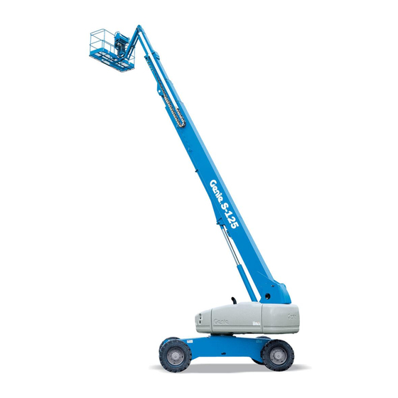
Sign In
Upload
Manuals
Brands
Genie Manuals
Boom Lifts
S-105
Genie S-105 Manuals
Manuals and User Guides for Genie S-105. We have
9
Genie S-105 manuals available for free PDF download: Service Manual, Service And Repair Manual, Maintenance Manual, Operator's Manual, Quick Reference Manual
Genie S-105 Service Manual (497 pages)
Brand:
Genie
| Category:
Lifting Systems
| Size: 17.13 MB
Table of Contents
Table of Contents
7
Hydraulic Specifications
24
Perkins Engine 1004-42 Specifications
25
Cummins Engine B3.9L Specifications
26
Hydraulic Hose and Fitting Torque Specifications
28
Theory of Operation
29
Pre-Delivery Preparation
35
Maintenance Inspection Report
37
Inspect the Manuals and Decals
39
Perform Pre-Operation Inspection
40
Perform Function Tests
40
Perform Engine Maintenance - Perkins Models
41
Perform Engine Maintenance - Cummins Models
41
Perform Engine Maintenance - Deutz Models
42
Check the Hydraulic Filter Condition Indicators
42
Test the Auxiliary Power Operation
44
Test the Tilt Sensor and Alarm
44
Test the Operating Envelope
45
Perform 30 Day Service
46
Perform Engine Maintenance - Perkins Models
46
Perform Engine Maintenance - Deutz Models
47
Grease the Turntable Rotation Bearing and Rotate Gear
47
Extendable Axle Lubrication System
48
Replace the Drive Hub Oil
49
Inspect the Batteries
50
Inspect the Electrical Wiring
51
Check the Oil Cooler and Cooling Fins - Deutz Models
53
Inspect the Engine Air Filter
53
Test the Alarm Package (if Equipped)
54
Perform Engine Maintenance - Deutz Models
55
Perform Engine Maintenance - Cummins Models
55
Check the Exhaust System
56
Inspect the Tires, Wheels and Lug Nut Torque
57
Check the Drive Hub Oil Level and Fastener Torque
57
Confirm the Proper Brake Configuration
58
Check and Adjust the Engine RPM
59
Test the Key Switches
62
Test the Ground Control Override
63
Test the Platform Self-Leveling
64
Test the Safety Envelope and Circuits
65
Test the Engine Idle Select Operation
72
Test the Drive Brakes
73
Test the Drive Speed - Stowed Position
73
Test the Drive Speed - Raised or Extended Position
74
Perform Hydraulic Oil Analysis
75
Inspect the Boom Extend/Retract Cables
75
Perform Engine Maintenance - Deutz Models
77
Perform Engine Maintenance - Cummins Models
77
Perform Engine Maintenance - Perkins Models
78
Replace the Engine Air Filter Element
78
Grease the Platform Overload Mechanism (if Equipped)
79
Test the Platform Overload System (if Equipped)
79
Check the Boom Wear Pads
82
Check the Extendable Axle Wear Pads
83
Check the Free-Wheel Configuration
84
Check the Turntable Rotation Bearing Bolts
85
Check the Turntable Rotation Gear Backlash
86
Replace the Drive Hub Oil
88
Grease the Turntable Rotatiion Bearing and Rotate Gear
90
Inspect for Turntable Bearing Wear
90
Perform Engine Maintenance - Deutz Models
91
Perform Engine Maintenance - Perkins Models
92
Perform Engine Maintenance - Cummins Models
92
Replace the Hydraulic Filter Elements
93
Test or Replace the Hydraulic Oil
95
Perform Engine Maintenance - Cummins Models
97
Perform Engine Maintenance - Perkins Models
97
Perform Engine Maintenance - Perkins Models
98
Perform Engine Maintenance - Deutz Models
98
Perform Engine Maintenance - Perkins Models
99
Perform Engine Maintenance - Deutz Models
99
Perform Engine Maintenance - Perkins Models
100
Perform Engine Maintenance - Deutz Models
101
Perform Engine Maintenance - Perkins Models
101
Perform Engine Maintenance - Deutz Models
102
Replace the Boom Extend/Retract Cables
102
Fault Code Chart
105
Platform
105
Display Not Active
113
Engine will Not Crank over
118
Engine Cranks over but will Not Start
124
Engine High Idle Inoperative
130
Engine Low Idle Inoperative
132
All Functions Inoperative, Engine Starts and Runs
133
Boom Up/Down, Extend/Retract, Turntable Rotate and
134
Drive, Steer and Axle Extend/Retract Functions Operational
134
All Platform, Steering and Axle Functions Inoperative
135
All Other Functions Operational
135
Ground Controls Inoperative, Platform Controls Operate Normally
140
Platform Controls Inoperative, Ground Controls Operate Normally
142
Boom Angle Switch Fault
144
Boom up Function Inoperative
147
Boom down Function Inoperative
151
Boom Length Switch Fault
156
Boom Extend Function Inoperative
160
Boom Retract Function Inoperative
169
Electrical Components
318
Relay Layout
326
Drive Chassis Controller Pin Legend
327
Platform Controller Pin Legend
328
Turntable Controller Pin Legend
329
Electrical Schematic Legend - Drive Chassis (DCON) and Platform Controls (PCON)
330
Electrical Schematic
330
Electrical Schematic Legend - Ground Controls (TCON)
331
Electrical Schematic
331
Safety Circuit Schematic
335
Electrical Schematic - Generators
336
Electrical Schematic - Deutz Models
337
Electrical Schematic - Cummins and Perkins Models
338
Hydraulic Symbols Legend
340
Repair Procedures
353
Display Module
354
Platform Controls
356
Joystick Controllers
356
Circuit Boards
357
Membrane Decal
358
Foot Switch
366
Advertisement
Genie S-105 Service Manual (317 pages)
Brand:
Genie
| Category:
Boom Lifts
| Size: 8.38 MB
Table of Contents
Table of Contents
7
Introduction
2
Serial Number Information
2
Serial Number Legend
3
Safety Rules
5
Personal Safety
6
Table of Contents
7
Machine Specifications
19
Hydraulic Oil Specifications
22
Hydraulic Component Specifications
23
Deutz Engine BF4L 2011 Specifications
26
Deutz Engine Td2011L04I Specifications
27
Perkins Engine 1104C-44 Specifications
30
Perkins Engine 804D-33T Specifications
32
Cummins Engine B3.3T Specifications
34
Cummins Engine B3.9L Specifications
35
Cummins Engine B4.5L Specifications
36
Machine Torque Specifications
37
Hydraulic Hose and Fitting Torque Specifications
37
Manifold Plug Torque Specifications
38
Observe and Obey
41
Pre-Delivery Preparation
43
Maintenance Inspection Report
45
Checklist a Procedures
47
Inspect the Manuals and Decals
47
Perform Pre-Operation Inspection
48
Perform Function Tests
48
Perform Engine Maintenance - Perkins Models
49
Perform Engine Maintenance - Cummins Models
49
Check the Hydraulic Filter Condition Indicators
50
Perform 30 Day Service
51
Perform Engine Maintenance - Perkins Models
52
Perform Engine Maintenance - Deutz Models
52
Grease the Turntable Rotation Bearing and Rotate Gear
53
Grease the Extendable Axles
53
Replace the Drive Hub Oil
54
Bodily Injury Hazard. Spraying
55
Checklist B Procedures
56
Inspect the Batteries
56
Inspect the Electrical Wiring
57
Check the Engine Oil Cooler and Cooling Fins - Deutz Models
59
Inspect the Engine Air Filter
60
Checklist B Procedures
60
B-6 Perform Engine Maintenance - Deutz Models
61
Check the Exhaust System
62
B-7 Perform Engine Maintenance - Cummins Models
62
Inspect the Tires, Wheels and Lug Nut Torque
63
Check the Dirve Hub Oil Level and Fastener Torque
64
Confirm the Proper Brake Configuration
65
Check and Adjust the Engine RPM
66
Test the Key Switches
69
Test the Ground Control Override
70
Test the Platform Self-Leveling
71
Test the Safety Envelope and Circuits
72
Inspect the Fuel and Hydraulic Tank Cap Venting Systems
78
Test the Engine Idle Select Operation
79
Test the Drive Brakes
80
Test the Drive Speed - Stowed Position
80
Test the Drive Speed - Raised or Extended Position
81
Inspect the Boom Extend/Retract Cables
82
Checklist C Procedures
84
Perform Engine Maintenance - Deutz Models
84
Perform Engine Maintenance - Cummins Models
84
Perform Engine Maintenance - Perkins Models
85
Replace the Engine Air Filter
85
Grease the Platform Overload Mechanism (if Equipped)
86
Test the Platform Overload System (if Equipped)
86
Checklist D Procedures
89
Check the Boom Wear Pads
89
Check the Extendable Axle Wear Pads
90
Check the Free-Wheel Configuration
91
Check the Turntable Rotation Bearing Bolts
92
Check the Turntable Rotation Gear Backlash
93
Replace the Drive Hub Oil
95
Inspect for Turntable Bearing Wear
97
Perform Engine Maintenance - Deutz Models
98
Perform Engine Maintenance - Perkins Models
98
Perform Engine Maintenance - Cummins Models
99
Replace the Hydraulic Filter Elements
99
Checklist E Procedures
102
Test or Replace the Hydraulic Oil
102
Perform Engine Maintenance - Cummins Models
104
Perform Engine Maintenance - Perkins Models
104
Perform Engine Maintenance - Perkins Models
105
Perform Engine Maintenance - Deutz Models
105
Perform Engine Maintenance - Perkins Models
106
Perform Engine Maintenance - Deutz Models
106
Perform Engine Maintenance - Perkins Models
107
Perform Engine Maintenance - Deutz Models
108
Perform Engine Maintenance - Perkins Models
108
Perform Engine Maintenance - Deutz Models
109
Replace the Boom Extend/Retract Cables
109
Repair Procedures
111
Display Module
112
Platform Controls
116
Circuit Boards
117
Membrane Decal
118
Joystick Controllers
119
Return to
120
Specifications
125
Platform Components
126
Platform
126
Platform Leveling Cylinder
126
Platform Rotator
128
Platform Level Sensor
131
Platform Overload System
132
Jib Boom Components, S-105 and S-125 Models
136
Jib Boom Lift Cylinder, S-105 and S-125 Models
137
Boom Components
138
Cable Track
139
Boom
142
Boom Lift Cylinder
153
Extension Cylinders
155
Boom Extend/Retract Cables
159
Turntable Covers
163
RPM Adjustment
165
Flex Plate
165
Oil Pressure and Coolant Temperature Sending Units, Cummins and Perkins Models
167
Oil Pressure and Temperature Sending Units, Deutz Models
167
Ground Controls
168
Circuit Boards
168
Membrane Decal
169
Control Relays
170
Limit Switches
172
Limit Switch and Level Sensor Locations
176
Limit Switch Functions
177
Hydraulic Pumps
180
Function Pumps
180
Drive Pump
181
Auxiliary Pump
184
Function Manifold Components, S-100 and S-105 Models (Serial Number 136)
186
Function Manifold Components, S-100 and S-105 Models (after Serial Number 136)
190
Valve Adjustments - Function Manifold, S-100 and S-105 Models
194
Proportional Valves - Function Manifold
195
Function Manifold Components, S-120 and S-125 Models (before Serial Number 431)
196
Function Manifold Components, S-120 and S-125 Models (from Serial Number 431 to 574)
200
Function Manifold Components, S-120 and S-125 Models (after Serial Number 574)
204
Valve Adjustments - Function Manifold, S-120 and S-125 Models
208
Proportional Valves - Function Manifold
209
Platform Manifold Components, S-100 and S-120 Models
210
Platform Manifold Components, S-105 and S-125 Models
212
Proportional Valves - Platform Manifolds
214
Platform Rotate Counterbalance Valve Manifold Components
214
Turntable Rotation Manifold Components
215
Steer and Axle Extend/Retract Manifold Components - View 1
216
Steer and Axle Extend/Retract Manifold Components - View 2
218
Valve Adjustments - Steer and Axle Extend/Retract Manifold
222
Traction Manifold Components (S-100/105 before Serial Number 291) (S-120/125 before Serial Number 1195)
224
Traction Manifold Components (S-100/105 after Serial Number 290) (S-120/125 after Serial Number 1194)
228
Valve Adjustments - Traction Manifold
232
Valve Coils
232
Electrocution Hazard. Contact with Electrically Charged Circuits Could Result in Death or Serious Injury
233
Remove All Rings, Watches and Other Jewelry
233
Fuel and Hydraulic Tanks
235
Fuel Tank
235
Hydraulic Tank
236
Turntable Rotation Components
238
Turntable Rotation Hydraulic Motor and Drive Hub
238
Axle Components
242
Steer Sensors
242
Yoke and Hub
244
Drive Motor
246
Drive Hub
247
Steering Cylinders
248
Extendable Axles
249
Be Sure that All Necessary Tools and Test Equipment Are Available and Ready for Use
253
Control System Fault Codes
261
Software
262
Immediately Tag and Remove from Service a Damaged or Malfunctioning Machine
262
Repair any Machine Damage or Malfunction before Operating the Machine
262
Troubleshooting and Repair Procedures Shall be Completed by a Person Trained and Qualified on the Repair of this Machine
262
Before Troubleshooting
262
Read, Understand and Obey the Safety Rules and Operating Instructions Printed in the
262
About this Section
262
Schematics
263
Circuit Numbering
264
Wire Color Legend
266
Section 6 • Schematics
267
Limit Switches
270
Relay Layout
272
Drive Chassis Controller Pin Legend
273
Platform Controller Pin Legend
274
Turntable Controller Pin Legend
275
Electrical Symbols Legend
276
Hydraulic Symbols Legend
277
Safety Circuit Schematic
279
Engine Options- Perkins and Cummins
281
(S-100/105 before Serial Number 219) (S-120/125 before Serial Number 933)
281
Engine Options- Perkins
283
(S-100/105 from Serial Number 219 to 247) (S-120/125 from Serial Number 933 to 984)
284
Engine Options- Perkins
284
(S-100/105 from Serial Number 248) (S-120/125 from Serial Number 985)
285
Engine Options- Cummins
287
(S-100/105 from Serial Number 219 to 247) (S-120/125 from Serial Number 933 to 984)
288
Engine Options- Cummins
288
(S-100/105 from Serial Number 248) (S-120/125 from Serial Number 985)
289
Electrical Schematic - Generator Options
291
A Electrical Schematic - Generator Options
292
Electrical Schematic - 12 Kw Generator (Welder Option)
293
Hydraulic Schematic - 12 Kw Generator (Welder Option)
295
Hydraulic Schematic
296
(Serial Number 136)
297
Hydraulic Schematics
298
Hydraulic Schematic
299
From Serial Number 291 to Serial Number 738)
301
Hydraulic Schematic
301
From Serial Number 739)
303
Hydraulic Schematic
305
(From Serial Number 404 to Serial Number 430)
305
Hydraulic Schematic
306
(From Serial Number 431 to Serial Number 1194)
307
Hydraulic Schematic
307
(From Serial Number 1195 to Serial Number 2634)
309
Hydraulic Schematic
309
(From Serial Number 2635)
311
Genie S-105 Service And Repair Manual (303 pages)
Brand:
Genie
| Category:
Lifting Systems
| Size: 20.35 MB
Table of Contents
Introduction
3
Introduction
4
Serial Number Legend
4
No.
4
Safety Rules
5
Table of Contents
7
Specifications
15
Part
15
Hydraulic Specifications
20
Hydraulic Component Specifications
22
Deutz Engine BF4L 2011 Specifications
26
Deutz Engine TD 2.9 Specifications
28
Perkins Engine 1004-42 Specifications
32
Perkins Engine 1104C-44 Specifications
33
Perkins Engine 804D-33T Specifications
34
Cummins Engine B3.3T Specifications
36
Cummins Engine B3.9L Specifications
37
Cummins Engine B4.5L Specifications
38
Machine Torque Specifications
39
Manifold Plug Torque Specifications
39
Hydraulic Hose and Fitting Torque Specifications
40
Repair Procedures
45
Display Module
46
Platform Controls
50
Circuit Boards
51
Membrane Decal
52
Joystick Controllers
53
Platform Components
60
Platform
60
Platform Leveling Cylinder
60
Platform Rotator
62
Platform Level Sensor
65
Platform Overload System
66
Platform Overload Recovery Message(Software V3.14 and Later)
69
Jib Boom Components, S-105 and S-125 Models
71
Jib Boom Lift Cylinder, S-105 and S-125 Models
72
Boom Components
73
Cable Track
74
Boom
77
Boom Lift Cylinder
88
Extension Cylinders
90
Boom Extend/Retract Cables
94
Turntable Covers
98
Engines
100
RPM Adjustment
100
Flex Plate
100
Oil Pressure and Coolant Temperature Sending Units, Cummins and Perkins Models
102
Oil Pressure and Temperature Sending Units, Deutz Models
102
Ground Controls
103
Circuit Boards
103
Membrane Decal
104
Control Relays
105
Limit Switches
107
Limit Switch and Level Sensor Locations
111
Limit Switch Functions
112
Hydraulic Pumps
115
Function Pumps
115
Drive Pump
116
Auxiliary Pump
119
Manifolds
121
Function Manifold Components, S-100 and S-105 Models (Serial Number 136)
121
Function Manifold Components, S-100 and S-105 Models (after Serial Number 136)
125
Valve Adjustments - Function Manifold, S-100 and S-105 Models
129
Proportional Valves - Function Manifold
130
Function Manifold Components, S-120 and S-125 Models (before Serial Number 431)
131
Function Manifold Components, S-120 and S-125 Models (from Serial Number 431 to 574)
135
Function Manifold Components, S-120 and S-125 Models (after Serial Number 574)
139
Valve Adjustments - Function Manifold, S-120 and S-125 Models
143
Proportional Valves - Function Manifold
144
Platform Manifold Components, S-100 and S-120 Models
145
Platform Manifold Components, S-105 and S-125 Models
147
Proportional Valves - Platform Manifolds
149
Platform Rotate Counterbalance Valve Manifold Components
149
Turntable Rotation Manifold Components
150
Steer and Axle Extend/Retract Manifold Components - View 1
155
Valve Adjustments - Steer and Axle Extend/Retract Manifold
157
Traction Manifold Components (S-100/105 before Serial Number 291) (S-120/125 before Serial Number 1195)
159
Traction Manifold Components (S-100/105 after Serial Number 290) (S-120/125 after Serial Number 1194)
163
Valve Adjustments - Traction Manifold
167
Valve Coils
167
Fuel and Hydraulic Tanks
170
Fuel Tank
170
Hydraulic Tank
171
Turntable Rotation Components
173
Turntable Rotation Hydraulic Motor and Drive Hub
173
Axle Components
177
Steer Sensors
177
Yoke and Hub
179
Drive Motor
181
Drive Hub
182
Steering Cylinders
183
Extendable Axles
184
Diagnostic Codes
187
Control System Fault Codes
195
Deutz TD 2.9 L4 Engine Fault Codes
199
Perkins 854F-34T Engine Fault Code
214
Software
223
Circuit Numbering
226
Wire Color Legend
228
Limit Switches
232
Relay Layout
234
Drive Chassis Controller Pin Legend
235
Platform Controller Pin Legend
236
Turntable Controller Pin Legend
237
Engine Relay and Fuse Panel Legend
238
Deutz TD2011 and Perkins 1104D Models
238
Engine Relay and Fuse Panel Legend - Deutz TD2.9 Models
239
Engine Relay and Fuse Panel Legend - Perkins 854F Models
240
Telematics Connector Pin Legend
241
Electrical Symbols Legend
242
Hydraulic Symbols Legend
243
Safety Circuit Schematic
245
Engine Options- Perkins and Cummins
247
Engine Options- Perkins
249
(S-100/105 from Serial Number 219 to 247) (S-120/125 from Serial Number 933 to 984)
249
Engine Options- Perkins
250
(S-100/105 from Serial Number 248) (S-120/125 from Serial Number 985)
251
Engine Options- Perkins
253
(S-100/105/120/125 from Serial Number 874)
253
Engine Options- Cummins
255
(S-100/105 from Serial Number 219 to 247) (S-120/125 from Serial Number 933 to 984)
255
Engine Options- Cummins
256
(S-100/105 from Serial Number 248) (S-120/125 from Serial Number 985)
257
Electrical Schematic - Generator Options
259
Electrical Schematic - 12 Kw Generator (Welder Option)
261
Perkins 1104D-44T Engine Electrical Schematic
263
Perkins 854F-34T Engine Electrical Schematic
265
Perkins 854F-34T Engine Electrical Harness
267
Deutz TD2.9 Engine Electrical Schematic
271
Deutz TD2.9 Engine Electrical Harness
273
Hydraulic Schematic - 12 Kw Generator (Welder Option)
275
Hydraulic Schematic - 12 Kw Generator
276
(Serial Number 136)
277
Hydraulic Schematic
277
Hydraulic Schematic
278
From Serial Number 291 to Serial Number 738)
281
Hydraulic Schematic
281
From Serial Number 739)
283
Hydraulic Schematic
283
(From Serial Number 404 to Serial Number 430)
285
Hydraulic Schematic
285
S-100 • S-105 • S-120 •
286
(From Serial Number 431 to Serial Number 1194)
287
Hydraulic Schematic
287
(From Serial Number 1195 to Serial Number 2634)
289
Hydraulic Schematic
289
(From Serial Number 2635 to Serial Number 3145)
291
Hydraulic Schematic
291
Hydraulic Schematic
292
Advertisement
Genie S-105 Maintenance Manual (182 pages)
Brand:
Genie
| Category:
Boom Lifts
| Size: 8.52 MB
Table of Contents
Table of Contents
9
Models Included in this Manual
3
Introduction
3
Identifying the Correct Procedure for Your Model
4
Find Additional Manuals for Your Model
4
Revision History
5
Safety Rules
7
Table of Contents
9
Performance Specifications
15
Function Speeds - S-100, S-105 and S-100HD
15
Function Speeds - S-120, S-125 and S-120HD
16
Function Speeds - All Other Models
17
Maintenance Manual October 2018 Performance Specifications
18
Jib Boom down
19
Jib Boom Rotate
19
Jib Boom up
19
Primary Boom Extend
19
Primary Boom Retract
19
Secondary Boom down
19
Secondary Boom up
19
Turntable Rotate
20
Platform Level (10° Range of Motion)
21
Platform Rotate
21
Drive Speeds
23
Ansi/Csa
25
Tires and Wheels
26
Torque Specifications
26
Trax Torque Specifications
27
Engine Operator and Maintenance Manuals
28
Engine Specifications
28
Deutz Engine Models
29
Perkins Engine Models
30
Ford Engine Models
32
Kubota Engine Models
32
GM Engine Models
33
Continental Engine Models
34
Cummins Engine Models
34
Hydraulic Relief Valves
35
Hydraulic Specifications
35
Hydraulic and Drive Hub Fluid Capacities
38
Hydraulic Oil Specifications
40
Hydraulic Hose and Fitting Torque Specifications
43
Torque Procedure
44
Introduction
46
Maintenance Procedures
46
Maintenance Schedule
48
Pre-Delivery Preparation Report
49
Scheduled - Quarterly October 2018 Maintenance Inspection Report - Booms
50
Scheduled Maintenance Inspection Report - Quarterly or Frequent
50
Boom(S) and Platform
51
Drive Chassis
51
Scheduled Maintenance Inspection Report - Annual
51
Turntable Mechanicals and Hydraulics
51
Programmed Maintenance Inspection Report - Booms
52
Commissioning Procedures
53
Perform 50 Hour Service
53
Perform Engine Maintenance - 50 Hours
53
Perform 150 Hour Service
54
Check for Open Bulletins and Owner Registration
55
Quarterly Maintenance Procedures
55
Battery Inspection
56
Inspect the Electrical Wiring
58
Inspect the Electrical Contactor - DC / Bi-Energy Models
59
Check the Exhaust System
60
Inspect the Tires, Wheels and Lug Nut Torque
60
Check the Generator Belts and Pulleys, Bi-Energy Models
61
Check the Oscillate Directional Valve Linkage (if Equipped)
62
Visual Inspection of the Hydraulic Oil
63
Inspect the Hydraulic Filters
64
Check and Adjust the Engine RPM
65
Test the Ground Control Override
70
Test the Alarm Package (if Equipped
71
Test the Alarm Package (if Equipped)
71
Test the Emergency Power System
72
Test the Engine Idle Select - Engine Models
72
Test the Engine Idle Select Operation
72
Test the Fuel Select Operation - Gasoline/Lpg Models
74
Inspect the Calibration Decal - ALC1000 Models
75
Test the Recovery Mode System - ALC-1000 Models
76
Test the Recovery System - ALC-1000 Models
76
Test the Platform Self-Leveling
77
Confirm the Proper Brake Configuration
78
Test the Drive Brakes
78
Test the Drive Speed - Raised or Extended Position
79
Test the Drive Speed - Stowed Position
79
Test the Drive Speed - Raised and Extended Position
80
Test the Drive Speed - Raised and Extended, ALC1000 Models
80
Sx-105Xc, Sx-125Xc, Sx-135Xc
82
Test the Turntable Level Sensor
82
XC, SX-125 XC, SX-135 XC, SX-150 and SX-180
82
Test the Secondary Boom Angle Sensor
84
Test the Secondary Boom Angle Sensor - Z-135/70 and ZX-135/70
84
Test the Primary Boom Angle Sensor - Z-135/70 and
86
Test the Primary Boom Angle Sensor - Z-135/70 and ZX-135/70
86
Test the Primary Boom Angle Sensor
89
XC, SX-125 XC, SX-135 XC, SX-150 and SX-180
89
Test the Safety Envelope Limit Switches
94
Test the Safety Envelope Limit Switches - Z-135/70, ZX-135/70, SX-105
94
Test the Primary Boom Angle Sensor
98
Test the Primary Boom Angle Sensor - Z-80/60
98
Test the Safety Envelope and Circuits
99
Test the Safety Envelope and Circuits - Z-80/60
99
Check the Safety Envelope Limit Switches and Angle Sensor - S-60X, S-80X, and S-60XC to S60XC-45000
101
And S-125
103
Test the Safety Envelope and Circuits
103
Test the Aircraft Protection System (if Equipped)
109
Inspect the Boom Extend/Retract Cables - All Models
111
Test the Operator Protection Alarm (if Equipped
111
Test the Operator Protection Alarm (if Equipped)
111
Test the Recovery Mode System - ALC-600 Models
112
S60Xcm-101, S-65 XC, S-80 Hf, S-85 Hf, S-80 XC, S-85 XC
113
Test the Primary Boom Angle Sensor - S-60 XC from S60XCH-45001 and S60XCM-101, S-65 XC, S-80 HF, S-85 HF, S-80 XC, S-85 XC
115
Test the Primary Boom Angle Sensor - S-60XC from
115
Annual Maintenance Procedures
117
Grease the Turntable Rotation Bearing and Rotate Gear
117
Check the Turntable Rotation Bearing Bolts
118
Inspect for Turntable Bearing Wear
119
Check the Extendable Axle - S-100, S-105, S-120 and S-125
120
Perform Maintenance- Jib Rotate Bearing
121
Test the Bypass/Recovery Key Switch - ALC1000 Models
122
Grease the Platform Overload Mechanism (if Equipped)
124
S-80XC, S-85XC and Z-45XC Models)
125
Test the Platform Overload System - All Models
125
Test the Platform Overload System - ALC1000 Models
127
Test the Platform Load Sense System - S-60 HC
128
Inspect the Boom Extend/Retract Cables - S-60/65 and S-80/85 Models
129
Inspect the Boom Extend/Retract Cables
131
XC and SX-125 XC
131
Inspect the Boom Extend and Retract Cables - SX-135
133
Check the Drive Hub Oil Level and Fastener Torque
137
Test the Dual Capacity and Platform Overload System
139
XC, SX-125 XC and SX-135 XC
139
Test the Dual Capacity and Platform Overload System - S-60 XC from
141
Z-45 XC Models
141
XC, S-85 XC
142
And Z-62 Models
144
P0-1 Check the Track Tension and Fastener Torque, TRAX Models
144
Programmed Maintenance Procedures
144
P0-2 Check the Track Tension and Fastener Torque, TRAX Models
145
S-40 and S-45 Models
145
P0-3 Grease the Extendable Axles - S-100, S-105, S-120 and S-125
147
P0-4 Continental Engine Maintenance - under 1000 Hours
148
P0-5 Cummins Engine Maintenance - under 1000 Hours
149
P0-6 Deutz Engine Maintenance - under 1000 Hours
150
P0-7 Ford Engine Maintenance - under 1000 Hours
151
P0-8 Kubota Engine Maintenance - under 1000 Hours
152
P0-9 Perkins Engine Maintenance - under 1000 Hours
153
P0-10 GM .998L Engine Maintenance - under 1000 Hours
154
P0-11 GM 3.0L Engine Maintenance - under 1000 Hours
155
P1-1 Perform Engine Maintenance - 1000 Hours
156
P1-2 Replace the Drive Hub Oil
157
P2-1 Perform Engine Maintenance - 2000 Hours
160
P2-2 Test or Replace the Hydraulic Oil
162
P2-3 Replace the Hydraulic Filters
163
P2-4 Check the Free-Wheel Configuration
165
P2-5 Check the Boom Wear Pads
167
P2-6 Check the Extendable Axle Wear Pads - S-100, S-105, S-120, S-125, S-100HD and S-120HD
170
P2-7 Check the Turntable Rotation Gear Backlash
170
P2-8 Grease the Steer Axle Wheel Bearings, All 2WD Models, Except S-60, S-65, Z-60 DC/FE and Z-62
171
DC/FE and Z-62
173
P3-1 Perform Engine Maintenance - 3000 Hours
174
P4-1 Perform Engine Maintenance - 4000 Hours
175
P5-1 Perform Engine Maintenance - 5000 Hours
176
P6-1 Perform Engine Maintenance - 6000 Hours
176
P12-1 Perform Engine Maintenance - 12000 Hours
177
P12-2 Remove and Inspect the Boom Extend/Retract Cables
177
Cable Replacement Criteria
180
Genie S-105 Maintenance Manual (157 pages)
Brand:
Genie
| Category:
Boom Lifts
| Size: 5.94 MB
Table of Contents
Introduction
3
Introduction
2
Models Included in this Manual
3
Identifying the Correct Procedure for Your Model
3
Find Additional Manuals for Your Model
3
Revision History
4
Safety Rules
6
Personal Safety
7
Table of Contents
8
April
12
Performance Specifications
13
Function Speeds - S-100, S-105 and S-100HD
13
April
13
Function Speeds - S-120, S-125 and S-120HD
14
Function Speeds - All Other Models
15
Drive Speeds
19
Torque Specifications
21
Tires and Wheels
21
TRAX Torque Specifications
22
Engine Specifications
23
Engine Operator and Maintenance Manuals
23
Deutz Engine Models
24
Perkins Engine Models
25
Ford Engine Models
26
Kubota Engine Models
27
GM Engine Models
28
Continental Engine Models
28
Cummins Engine Models
29
Hydraulic Specifications
30
Hydraulic Relief Valves
30
Hydraulic and Drive Hub Fluid Capacities
33
Hydraulic Oil Specifications
35
Hydraulic Hose and Fitting Torque Specifications
38
Torque Procedure
39
Maintenance Procedures
41
Introduction
41
About this Section
42
Maintenance Schedule
43
Maintenance Inspection Report
43
Pre-Delivery Preparation Report
44
Scheduled
45
Scheduled Maintenance Inspection Report - Booms
45
Programmed Maintenance Inspection Report - Booms
46
Commissioning Procedures
47
Perform 50 Hour Service
47
Perform Engine Maintenance - 50 Hours
47
Perform 150 Hour Service
48
Quarterly Maintenance Procedures
49
Check for Open Bulletins and Owner Registration
49
Battery Inspection
50
Inspect the Electrical Wiring
52
Inspect the Electrical Contactor - DC / Bi-Energy Models
53
Check the Exhaust System
54
Inspect the Tires, Wheels and Lug Nut Torque
54
Check the Generator Belts and Pulleys, Bi-Energy Models
55
Check the Oscillate Directional Valve Linkage (if Equipped)
56
Visual Inspection of the Hydraulic Oil
57
Inspect the Hydraulic Filters
58
Check and Adjust the Engine RPM
59
Test the Ground Control Override
64
Test the Alarm Package (if Equipped)
64
Test the Emergency Power System
65
Test the Engine Idle Select - Engine Models
66
Test the Fuel Select Operation - Gasoline/Lpg Models
67
Inspect the Calibration Decal - ALC1000 Models
68
Test the Recovery Mode System - ALC-1000 Models
69
Test the Platform Self-Leveling
71
Confirm the Proper Brake Configuration
71
Test the Drive Brakes
72
Test the Drive Speed - Stowed Position
72
Test the Drive Speed - Raised or Extended Position
73
Test the Drive Speed - Raised and Extended, ALC1000 Models
74
Test the Drive Speed - Raised and Extended
74
Test the Turntable Level Sensor
75
Test the Turntable Level Sensor - Z-135/70, ZX135/70, SX-150 and
75
Z-135/70, ZX135/70, SX-150 and SX-180
75
Test the Secondary Boom Angle Sensor - Z-135/70 and ZX135/70
77
Test the Primary Boom Angle Sensor - Z-135/70 and ZX135/70
79
Test the Primary Boom Angle Sensor
79
Test the Primary Boom Angle Sensor - SX-150 and SX-180
82
Test the Primary Boom Angle Sensor
82
Test the Safety Envelope Limit Switches
84
Z-135/70, ZX135/70, SX-150 and SX-180 Models
86
Z-135/70, ZX135/70, SX-150 and
87
Test the Primary Boom Angle Sensor - Z-80/60
88
Test the Primary Boom Angle Sensor
88
Test the Safety Envelope and Circuits - Z-80/60
89
Test the Safety Envelope and Circuits
89
Check the Safety Envelope Limit Switches and Angle Sensor - S-60X, S-60XC and S-80X
91
Check the Safety Envelope Limit Switches and Angle Sensor - S-60X, S-60XC and
91
Test the Safety Envelope and Circuits
93
And S-125
93
Test the Aircraft Protection System (if Equipped)
99
Test the Aircraft Protection System (if Equipped
99
Test the Operator Protection Alarm (if Equipped)
101
Test the Operator Protection Alarm (if Equipped
101
Annual Maintenance Procedures
102
Grease the Turntable Rotation Bearing and Rotate Gear
102
Check the Turntable Rotation Bearing Bolts
103
Inspect for Turntable Bearing Wear
104
Check the Extendable Axle - S-100, S-105, S-120 and S-125
105
Perform Maintenance- Jib Rotate Bearing
106
Test the Bypass/Recovery Key Switch - ALC1000 Models
107
Grease the Platform Overload Mechanism (if Equipped)
110
Test the Platform Overload System - All Models, Except ALC1000 and S-60HC Models
110
Z-30/20N (Rj
110
Test the Platform Overload System - ALC1000 Models
112
Test the Platform Load Sense System - S-60 HC
114
Inspect the Boom Extend/Retract Cables - S-60 and S-80 Models
115
Inspect the Boom Extend/Retract Cables
116
And S-125 Models
116
Inspect the Boom Extend and Retract Cables
118
And SX-180 Models
118
Check the Drive Hub Oil Level and Fastener Torque
119
Programmed Maintenance Procedures
122
S-60, S-65 and Z-62 Models
122
S-40 and S-45 Models
123
P0-3 Grease the Extendable Axles - S-100, S-105, S-120 and S-125
125
P0-4 Continental Engine Maintenance - under 1000 Hours
126
P0-5 Cummins Engine Maintenance - under 1000 Hours
127
P0-6 Deutz Engine Maintenance - under 1000 Hours
128
P0-7 Ford Engine Maintenance - under 1000 Hours
129
P0-8 Kubota Engine Maintenance - under 1000 Hours
130
P0-9 Perkins Engine Maintenance - under 1000 Hours
131
P0-10 GM .998L Engine Maintenance - under 1000 Hours
132
P0-11 GM 3.0L Engine Maintenance - under 1000 Hours
133
P1-1 Perform Engine Maintenance - 1000 Hours
134
P1-2 Replace the Drive Hub Oil
135
P2-1 Perform Engine Maintenance - 2000 Hours
138
P2-2 Test or Replace the Hydraulic Oil
140
P2-3 Replace the Hydraulic Filters
141
P2-4 Check the Free-Wheel Configuration
143
P2-5 Check the Boom Wear Pads
145
Z-30/20N (Rj
146
Z-51/30J
147
P2-6 Check the Extendable Axle Wear Pads - S-100, S-105, S-120, S-125, S-100HD and S-120HD
148
P2-7 Check the Turntable Rotation Gear Backlash
148
P2-8 Grease the Steer Axle Wheel Bearings, All 2WD Models (Except S-60 / S-65, Z-60 DC/FE and Z-62)
149
Z-34/22 be
150
P2-9 Grease the Steer Axle Wheel Bearings, 2WD Models - S-60 /
151
P3-1 Perform Engine Maintenance - 3000 Hours
152
P4-1 Perform Engine Maintenance - 4000 Hours
153
P5-1 Perform Engine Maintenance - 5000 Hours
154
P6-1 Perform Engine Maintenance - 6000 Hours
154
P12-1 Perform Engine Maintenance - 12000 Hours
155
P12-2 Replace the Boom Extend/Retract Cables - S-100HD and S-120HD
155
P12-3 Replace the Boom Extend/Retract Cables - S-60 Models, S-80 Models, S-100, S-105, S-120, S-125, SX-150
156
Genie S-105 Maintenance Manual (178 pages)
Brand:
Genie
| Category:
Boom Lifts
| Size: 8.21 MB
Table of Contents
Table of Contents
9
Maintenance Procedures
42
Introduction
42
Maintenance Schedule
44
Pre-Delivery Preparation Report
45
Scheduled - Quarterly April 2018 Maintenance Inspection Report - Booms
46
Scheduled Maintenance Inspection Report - Quarterly or Frequent
46
Scheduled Maintenance Inspection Report - Annual
47
Programmed Maintenance Inspection Report - Booms
48
Commissioning Procedures
49
Perform 50 Hour Service
49
Perform Engine Maintenance - 50 Hours
49
Perform 150 Hour Service
50
Check for Open Bulletins and Owner Registration
51
Quarterly Maintenance Procedures
51
Battery Inspection
52
Inspect the Electrical Wiring
54
Inspect the Electrical Contactor - DC / Bi-Energy Models
55
Check the Exhaust System
56
Inspect the Tires, Wheels and Lug Nut Torque
56
Check the Generator Belts and Pulleys, Bi-Energy Models
57
Check the Oscillate Directional Valve Linkage (if Equipped)
58
Visual Inspection of the Hydraulic Oil
59
Inspect the Hydraulic Filters
60
Check and Adjust the Engine RPM
61
Test the Ground Control Override
66
Test the Alarm Package (if Equipped
67
Test the Alarm Package (if Equipped)
67
Test the Emergency Power System
68
Test the Engine Idle Select - Engine Models
68
Test the Engine Idle Select Operation
68
Test the Fuel Select Operation - Gasoline/Lpg Models
70
Inspect the Calibration Decal - ALC1000 Models
71
Test the Recovery Mode System - ALC-1000 Models
72
Test the Recovery System - ALC-1000 Models
72
Test the Platform Self-Leveling
73
Confirm the Proper Brake Configuration
74
Test the Drive Brakes
74
Test the Drive Speed - Raised or Extended Position
75
Test the Drive Speed - Stowed Position
75
Test the Drive Speed - Raised and Extended Position
76
Test the Drive Speed - Raised and Extended, ALC1000 Models
76
Test the Turntable Level Sensor
78
XC, SX-125 XC, SX-135 XC, SX-150 and SX-180
78
Test the Secondary Boom Angle Sensor - Z-135/70 and ZX-135/70
80
Test the Turntable Level Sensor
81
Test the Primary Boom Angle Sensor - Z-135/70 and ZX-135/70
82
Test the Secondary Boom Angle Sensor
82
Test the Primary Boom Angle Sensor
85
XC, SX-125 XC, SX-135 XC, SX-150 and SX-180
85
Test the Safety Envelope Limit Switches
90
XC, SX-125 XC, SX-135 XC, SX-150 and SX-180
90
Test the Primary Boom Angle Sensor
94
Test the Primary Boom Angle Sensor - Z-80/60
94
Test the Safety Envelope and Circuits
95
Test the Safety Envelope and Circuits - Z-80/60
95
Check the Safety Envelope Limit Switches and Angle
97
Check the Safety Envelope Limit Switches and Angle Sensor - S-60X, S-60XC and S-80X
97
And S-125
99
Test the Safety Envelope and Circuits
99
Test the Aircraft Protection System (if Equipped
105
Test the Aircraft Protection System (if Equipped)
105
Inspect the Boom Extend/Retract Cables - All Models
107
Test the Operator Protection Alarm (if Equipped)
107
Test the Recovery Mode System - ALC-600 Models
108
Test the Turntable Level Sensor - S-80 XC and S-85 XC
109
Test the Primary Boom Angle Sensor - S-80 XC, S-85 XC
111
Annual Maintenance Procedures
113
Grease the Turntable Rotation Bearing and Rotate Gear
113
Check the Turntable Rotation Bearing Bolts
114
Inspect for Turntable Bearing Wear
115
Check the Extendable Axle - S-100, S-105, S-120 and S-125
116
Perform Maintenance- Jib Rotate Bearing
117
Test the Bypass/Recovery Key Switch - ALC1000 Models
118
Grease the Platform Overload Mechanism (if Equipped)
120
All Models, Except ALC1000 and S-60HC Models
121
Test the Platform Overload System
121
Test the Platform Overload System - ALC1000 Models
123
Test the Platform Load Sense System - S-60 HC
124
Inspect the Boom Extend/Retract Cables - S-60 and S-80 Models
125
Inspect the Boom Extend/Retract Cables - S-100, S-105, S-120, S-125, SX-105 XC and SX-125 XC
127
Inspect the Boom Extend and Retract Cables
129
XC, SX-150 and SX-180
129
Check the Drive Hub Oil Level and Fastener Torque
133
Test the Dual Capacity and Platform Overload System
135
Test the Dual Capacity and Platform Overload System - S-80 XC and SX-85 XC
135
XC, SX-125 XC and SX-135 XC
135
Z-45 XC Models
137
P0-1 Check the Track Tension and Fastener Torque, TRAX Models
140
Programmed Maintenance Procedures
140
S-60, S-65 and Z-62 Models
140
P0-2 Check the Track Tension and Fastener Torque, TRAX Models
141
S-40 and S-45 Models
141
P0-3 Grease the Extendable Axles - S-100, S-105, S-120 and S-125
143
P0-4 Continental Engine Maintenance - under 1000 Hours
144
P0-5 Cummins Engine Maintenance - under 1000 Hours
145
P0-6 Deutz Engine Maintenance - under 1000 Hours
146
P0-7 Ford Engine Maintenance - under 1000 Hours
147
P0-8 Kubota Engine Maintenance - under 1000 Hours
148
P0-9 Perkins Engine Maintenance - under 1000 Hours
149
P0-10 GM .998L Engine Maintenance - under 1000 Hours
150
P0-11 GM 3.0L Engine Maintenance - under 1000 Hours
151
P1-1 Perform Engine Maintenance - 1000 Hours
152
P1-2 Replace the Drive Hub Oil
153
P2-1 Perform Engine Maintenance - 2000 Hours
156
P2-2 Test or Replace the Hydraulic Oil
158
P2-3 Replace the Hydraulic Filters
159
P2-4 Check the Free-Wheel Configuration
161
P2-5 Check the Boom Wear Pads
163
P2-6 Check the Extendable Axle Wear Pads - S-100, S-105, S-120, S-125, S-100HD and S-120HD
166
P2-7 Check the Turntable Rotation Gear Backlash
166
P2-8 Grease the Steer Axle Wheel Bearings, All 2WD Models, Except S-60, S-65, Z-60 DC/FE and Z-62
167
P2-9 Grease the Steer Axle Wheel Bearings, 2WD Models - S-60, S-65, Z-60 DC/FE and Z-62
169
P3-1 Perform Engine Maintenance - 3000 Hours
170
P4-1 Perform Engine Maintenance - 4000 Hours
171
P5-1 Perform Engine Maintenance - 5000 Hours
172
P6-1 Perform Engine Maintenance - 6000 Hours
172
P12-1 Perform Engine Maintenance - 12000 Hours
173
P12-2 Remove and Inspect the Boom Extend/Retract Cables
173
Cable Replacement Criteria
176
Genie S-105 Operator's Manual (71 pages)
Brand:
Genie
| Category:
Boom Lifts
| Size: 2.65 MB
Table of Contents
Table of Contents
2
Introduction
3
Symbol and Hazard Pictorials Definitions
5
General Safety
7
Personal Safety
10
Work Area Safety
11
Legend
22
Controls
23
Inspections
31
Workplace Inspection
42
Operating Instructions
47
Emergency Stop
48
Transport and Lifting Instructions
59
Maintenance
62
Specifications
65
S-100 • S-105 • S-120 • S-125 Part no
66
Genie S-105 Operator's Manual (44 pages)
Brand:
Genie
| Category:
Lifting Systems
| Size: 1.53 MB
Table of Contents
Table of Contents
2
Safety Rules
3
Legend
9
Controls
10
Pre-Operation Inspection
13
Maintenance
15
Function Tests
18
Workplace Inspection
24
Operating Instructions
25
Transport and Lifting Instructions
31
Decals
34
Specifications
38
Genie S-105 Quick Reference Manual (1 page)
Brand:
Genie
| Category:
Boom Lifts
| Size: 0.28 MB
Advertisement
Related Products
Genie S-100
Genie S-120
Genie S-125
Genie S-100HD
Genie S-120HD
Genie S-150
Genie S-180
Genie S-65
Genie S-60X
Genie S-40 TRAX
Genie Categories
Garage Door Opener
Lifting Systems
Boom Lifts
Security Camera
Digital Camera
More Genie Manuals
Login
Sign In
OR
Sign in with Facebook
Sign in with Google
Upload manual
Upload from disk
Upload from URL