Sign In
Upload
Manuals
Brands
Genie Manuals
Boom Lifts
S-40 TRAX
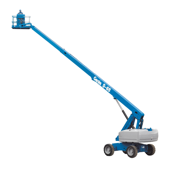
Genie S-40 TRAX Manuals
Manuals and User Guides for Genie S-40 TRAX. We have
13
Genie S-40 TRAX manuals available for free PDF download: Service Manual, Maintenance Manual, Service And Repair Manual, Operator's Manual, Operator's Manual Supplement
Genie S-40 TRAX Service Manual (325 pages)
Serial Number Range from S40-7001 to S4012-17231
Brand:
Genie
| Category:
Lifting Systems
| Size: 5.42 MB
Table of Contents
Table of Contents
9
Introduction
2
Serial Number Legend
5
Safety Rules
7
Table of Contents
9
Table of Contents
18
Machine Specifications
19
Hydraulic Oil Specifications
20
Manifold Component Specifications
23
Valve Coil Resistance Specifications
23
Ford LRG-425 EFI Engine Specifications
24
Ford DSG-423 EFI Engine Specifications
25
Deutz F3L-1011F Engine Specifications
26
Perkins 704-30 Engine Specifications
29
Perkins 404-22 Engine Specifications
30
Machine Torque Specifications
31
Hydraulic Hose and Fitting Torque Specifications
32
Pre-Delivery Preparation
36
Maintenance Inspection Report
38
Checklist a Procedures
40
Inspect the Decals and Manuals
40
Perform Pre-Operation Inspection
41
Perform Function Tests
41
Perform Engine Maintenance
41
Inspect the Track Components, TRAX Option
42
Perform 30 Day Service
43
Perform Engine Maintenance - Deutz and Ford Models
43
Replace the Drive Hub Oil
44
Perform Engine Maintenance - Perkins Models
45
Perform Engine Maintenance - Ford Models
46
Grease the Turntable Rotation Bearing and Rotate Gear
47
Perform Engine Maintenance - Deutz 1011F Models
47
Perform Engine Maintenance - Ford Models
48
Checklist B Procedures
49
Inspect the Battery
49
Inspect the Electrical Wiring
50
Inspect the Air Filter
51
Test the Key Switch
52
Perform Engine Maintenance - Deutz and Perkins Models
52
Check the Exhaust System
53
Check the Oil Cooler and Cooling Fins - Deutz Models
53
Inspect the Tires, Wheels and Lug Nut Torque
54
Check the Drive Hub Oil Level and Fastener Torque
55
Confirm the Proper Brake Configuration
56
Check and Adjust the Engine RPM
57
Test the Engine Idle Select
58
Test the Fuel Select Operation - Ford Models
59
Test the Ground Control Override
60
Check the Directional Valve Linkeage
60
Test the Platform Self-Leveling
61
Test the Drive Brakes
61
Test the Drive Speed - Stowed Position
62
Test the Drive Speed - Raised or Extended Position
62
Perform Hydraulic Oil Analysis
63
Test the Alarm Package (if Equipped) and the Descent Alarm
64
Inspect the Fuel and Hydraulic Tank Cap Venting System
65
Check the Track Tension and Fastener Torque, TRAX Option
66
Perform Engine Maintenance - Ford Models
67
Checklist C Procedures
68
Perform Engine Maintenance - Deutz and Perkins Models
68
Grease the Platform Overload Mechanism (if Equipped)
69
Replace the Engine Air Filter - Deutz and Perkins Models
72
Replace the Inline Fuel Strainer
73
Perform Engine Maintenance Ford Models
73
Checklist D Procedures
74
Check the Boom Wear Pads
74
Check the Turntable Rotation Bearing Bolts
75
Check the Free-Wheel Configuration
76
Replace the Drive Hub Oil
78
Replace the Hydraulic Filters
80
Inspect for Turntable Bearing Wear
81
Checklist E Procedures
83
Test or Replace the Hydraulic Oil
83
Grease the Steer Axle Wheel Bearings, 2WD Models
85
Perform Engine Maintenance - Deutz and Perkins Models
86
Perform Engine Maintenance - Ford Models
87
E-6 Perform Engine Maintenance - Deutz and Perkins Models
88
E-7 Perform Engine Maintenance - Deutz Models
89
E-9 Perform Engine Maintenance - Ford Models
90
Platform Controls
93
Circuit Board
93
Joysticks
94
Platform Components
99
Platform Leveling Slave Cylinder
99
Platform Rotator
100
Platform Overload System
102
Part No. 102521 S-40 •
104
Jib Boom Components
105
Jib Boom
105
Jib Boom Lift Cylinder
106
Boom Components
107
Cable Track
107
Boom
109
Boom Lift Cylinder
112
Platform Leveling Master Cylinder
114
Engines
115
RPM Adjustment - Deutz Models
115
RPM Adjustment - Perkins Models
115
Flex Plate
115
Engine Fault Codes - Ford Models
119
Hydraulic Pumps
120
Function Pump
120
Drive Pump
121
Manifolds
123
Function Manifold Components
123
Valve Adjustments - Function Manifold
127
Brake Manifold Components (before Serial Number 7569)
129
Brake/Two-Speed Manifold Components (after Serial Number 7568)
130
Valve Adjustments, Oscillate Relief Valve
133
Traction Manifold Components, 2WD (before Serial Number 7569)
134
Traction Manifold Components, 2WD (after Serial Number 7568)
135
Traction Manifold Components, 4WD (before Serial Number 7569)
137
Traction Manifold Components, 4WD (from Serial Number 7568 to 15822)
139
Traction Manifold Components, 4WD (from Serial Number 15823)
141
Valve Coils
144
Drive Oil Diverter Manifold Components (Welder Option)
146
Turntable Rotation Components
147
Turntable Rotation Assembly
147
Axle Components
149
Track Components
150
Track Assembly - TRAX Option
150
Generators
152
Hydraulic Generator
152
Electrical Symbols Legend
171
Hydraulic Symbols Legend
172
Ford DSG-423 Engine Relay Layout
173
Connector Pin Legend
174
Electrical Schematic, Deutz F3L 1011 Models
177
Ground Control Box Wiring Diagram
180
Deutz F3L-1011F Models
180
Platform Control Box Wiring Diagram
183
Deutz F3L-1011F Models
183
Platform Control Box Switch Panel Wiring Diagram
184
Deutz F3L-1011F Models
184
Electrical Schematic, Perkins 704-30 Models
187
Ground Control Box Wiring Diagram
191
Perkins 704-30 Models
191
Platform Control Box Wiring Diagram
192
Perkins 704-30 Models
192
Perkins 704-30 Models
193
Platform Control Box Switch Panel Wiring Diagram Perkins 704-30 Models
194
Perkins 404-22 Models (before Serial Number 14832)
229
Electrical Schematic Ford LRG-425 EFI Models (before Serial Number 7597)
237
Ground Control Box Wiring Diagram Ford LRG-425 EFI Models (before Serial Number 7597)
240
Platform Control Box Wiring Diagram Ford LRG-425 EFI Models (before Serial Number 7597)
243
Platform Control Box Switch Panel Wiring Diagram Ford LRG-425 EFI Models (before Serial Number 7597)
245
Ground Control Box Wiring Diagram Ford DSG-423 EFI Models (before Serial Number 14832)
285
Ground Control Box Wiring Diagram Ford DSG-423 EFI Models (from Serial Number 14832)
287
Platform Control Box Wiring Diagram Ford DSG-423 EFI Models (before Serial Number 14832)
289
Platform Control Box Wiring Diagram Ford DSG-423 EFI Models (from Serial Number 14832)
290
Platform Control Box Switch Panel Wiring Diagram Ford DSG-423 EFI Models (from Serial Number 11067 to 12509)
293
Platform Control Box Switch Panel Wiring Diagram Ford DSG-423 EFI Models (from Serial Number 12510)
295
Engine Harness, Ford LRG-425 EFI Models
296
(Before Serial Number 11067)
296
Joystick Connector Diagram
303
CTE Option Wiring Diagram
304
MTE Hydraulic Generator Option Wiring Diagram
306
Hydraulic Generator Wiring Diagram- Welder Option
308
(Before Serial Number 7569)
310
(Before Serial Number 7569)
311
(Before Serial Number 7569)
312
(Before Serial Number 7569)
313
Generator Hydraulic Schematic- Welder Option
322
Advertisement
Genie S-40 TRAX Service Manual (296 pages)
Brand:
Genie
| Category:
Boom Lifts
| Size: 9.54 MB
Table of Contents
Revision History
3
Introduction
2
Table of Contents
3
Reference Examples
4
2-1_Section 2_Specifications Page
4
3-3_Section 3_Maintenance Procedure Page
4
4-48_Section 4_Repair Procedure Page
4
6-5_Section 6_Schematic Page
4
Click on any Procedure or Page Number Highlighted in Blue to View the Update
4
Procedure / Schematic Page / Description
4
Revision History
4
Serial Number Legend
5
Safety Rules
6
Personal Safety
6
Electronic Version
4
Table of Contents
8
Schematics
13
Table of Contents
16
Specifications
17
Machine Specifications
17
Hydraulic Oil Specifications
18
Manifold Component Specifications
21
Valve Coil Resistance Specifications
21
Ford MSG-425 EFI Engine Specifications
22
Deutz D2011L03I Engine Specifications
24
Deutz D 2.9 L4 Engine Specifications
26
Perkins 404D-22 Engine Specifications
28
Perkins 404F-22 Engine Specifications
29
Machine Torque Specifications
31
TRAX Torque Specifications
31
Hydraulic Hose and Fitting Torque Specifications
32
Scheduled Maintenance Procedures
35
Pre-Delivery Preparation
37
Maintenance Inspection Report
39
Checklist a Procedures
41
Inspect the Decals and Manuals
41
Perform Function Tests
42
Perform Pre-Operation Inspection
42
Perform Engine Maintenance - Perkins Models
43
Perform Engine Maintenance- Ford Models
43
Inspect the Track Components, TRAX Option
44
Perform Engine Maintenance - Deutz Models
44
Check the High Pressure Hydraulic Filter Condition Indicator
45
Test the Oscillate Axle
45
Perform 30 Day Service
46
Replace the Drive Hub Oil
46
Perform Engine Maintenance - Ford Models
47
Perform Engine Maintenance - Perkins Models
47
Grease the Turntable Rotation Bearing and Rotate Gear
48
Perform Engine Maintenance - Ford Models
48
Perform Engine Maintenance - Ford Models
49
Checklist B Procedures
50
Inspect the Battery
50
Inspect the Electrical Wiring
51
Check the Exhaust System
53
Check the Oil Cooler and Cooling Fins - Deutz Models
54
Perform Engine Maintenance - Perkins Models
54
Confirm the Proper Brake Configuration
56
Inspect the Tires, Wheels and Lug Nut Torque
56
Check the Drive Hub Oil Level and Fastener Torque
57
Test the Ground Control Override
57
Test the Platform Self-Leveling
58
Test the Engine Idle Select
59
Test the Fuel Select Operation - Ford Models
60
Test the Drive Brakes
61
Test the Drive Speed - Stowed Position
62
Test the Drive Speed - Raised or Extended Position
63
Perform Hydraulic Oil Analysis
65
Inspect the Fuel and Hydraulic Tank Cap Venting System
66
Check the Track Tension and Fastener Torque, TRAX Option
67
Test the Emergency Power System
68
Perform Engine Maintenance - Ford Models
69
Checklist C Procedures
70
Grease the Platform Overload Mechanism (if Equipped)
70
Perform Engine Maintenance - Perkins Models
75
Perform Engine Maintenance - Deutz Models
76
Perform Engine Maintenance Ford Models
78
Check the Boom Wear Pads
80
Checklist D Procedures
80
Check the Turntable Rotation Bearing Bolts
81
Inspect for Turntable Bearing Wear
82
Check the Free-Wheel Configuration
84
Replace the Drive Hub Oil
84
Replace the Hydraulic Filters
86
Perform Engine Maintenance - Perkins Models
87
D-8 Perform Engine Maintenance - Deutz Models
88
Checklist E Procedures
89
Test or Replace the Hydraulic Oil
89
Grease the Steer Axle Wheel Bearings, 2WD Models
91
Perform Engine Maintenance - Perkins Models
92
Perform Engine Maintenance - Deutz Models
93
Perform Engine Maintenance - Perkins 404D-22 Models
94
Perform Engine Maintenance - Perkins Models
94
Perform Engine Maintenance - Deutz Models
95
Perform Engine Maintenance - Perkins 404F-22 Models
95
Repair Procedures
97
Circuit Board
98
Platform Controls
98
Joysticks
99
Platform Components
104
Platform Leveling Slave Cylinder
104
Platform Rotator
105
Platform Overload System
107
Jib Boom
110
Jib Boom Components
110
Jib Boom Lift Cylinder
111
Boom Components
112
Cable Track
112
Boom
114
Boom Lift Cylinder
117
Platform Leveling Master Cylinder
119
Flex Plate
120
RPM Adjustment - Perkins Models
120
Ford MSG-425 Engine Fault Codes
124
Function Pump
125
Hydraulic Pumps
125
Drive Pump
126
Function Manifold Components
128
Valve Adjustments - Function Manifold
132
Oscillate Directional Valve Components
135
Valve Adjustments, Oscillate Relief Valve
137
Traction Manifold Components, 2WD
138
Traction Manifold Components, 4WD
140
Drive Oil Diverter Manifold Components (Welder Option)
143
Valve Coils
144
Turntable Rotation Assembly
146
Turntable Rotation Components
146
Axle Components
148
Track Assembly - TRAX Option
149
Track Components
149
Hydraulic Generator
151
Fault Codes
153
Fault Codes - Control System
154
Fault Code Display - Deutz D 2.9 L4 and Perkins 404F-22 Models
158
Fault Code Display - Flashing and Solid Led's
159
Fault Code Display - Soft Key Functions and Icons
160
Fault Code Display - Main Menu Structure
161
Fault Codes - Deutz D 2.9 L4 Engine
162
Fault Codes - Ford MSG-425 Engine
180
Electrical Symbols Legend
188
Hydraulic Symbols Legend
189
Electrical Abbreviations Legend
190
Ford Engine Relay Layout
193
Connector Pin Legend
195
Deutz D 2.9 L4 Models
197
Engine Wire Harness
197
Engine Wire Harness
198
Deutz D 2.9 L4 Models
204
Ground Control Box Wiring Diagram - ANSI Deutz D 2.9 L4 Models
208
Platform Control Box Wiring Diagram - ANSI Deutz D 2.9 L4 Models
210
Platform Switch Panel Wiring Diagram - ANSI Deutz D 2.9 L4 Models
212
Perkins 404F-22 Models
213
Electrical Schematic - ANSI Perkins 404F-22 Models
214
Ground Control Box Wiring Diagram - ANSI Perkins 404F-22 Models
218
Platform Control Box Wiring Diagram - ANSI Perkins 404F-22 Models
220
Platform Switch Panel Wiring Diagram - ANSI Perkins 404F-22 Models
222
Ford MSG-425 EFI Models
234
Ground Control Box Wiring Diagram - ANSI / CSA Ford MSG-425 EFI Models
238
Platform Control Box Wiring Diagram - ANSI / CSA Ford MSG-425 EFI Models
240
Platform Switch Panel Wiring Diagram - ANSI / CSA Ford MSG-425 EFI Models
242
Electrical Schematic - CE Ford MSG-425 EFI Models
254
Ground Control Box Wiring Diagram - CE Ford MSG-425 EFI Models
258
Platform Control Box Wiring Diagram - CE Ford MSG-425 EFI Models
260
Platform Switch Panel Wiring Diagram - CE Ford MSG-425 EFI Models
261
Electrical Schematics - CE
264
Perkins 404D-22 Models
264
Platform Switch Panel Wiring Diagram - aus
272
Electrical Schematic - aus Ford MSG-425 EFI Models
274
Ford MSG-425 EFI Models
276
Ground Control Box Wiring Diagram - aus Ford MSG-425 EFI Models
278
Platform Control Box Wiring Diagram - aus Ford MSG-425 EFI Models
280
Platform Switch Panel Wiring Diagram - aus Ford MSG-425 EFI Models
281
CTE Option Wiring Diagram
283
Hydraulic Generator Option Wiring Diagram- MTE
285
12.5 Kw Hydraulic Generator Electrical Schematic- Welder Option
287
12.5 Kw Hydraulic Generator Wiring Diagram- Welder Option
289
Genie S-40 TRAX Maintenance Manual (182 pages)
Brand:
Genie
| Category:
Boom Lifts
| Size: 8.52 MB
Table of Contents
Table of Contents
9
Models Included in this Manual
3
Introduction
3
Identifying the Correct Procedure for Your Model
4
Find Additional Manuals for Your Model
4
Revision History
5
Safety Rules
7
Table of Contents
9
Performance Specifications
15
Function Speeds - S-100, S-105 and S-100HD
15
Function Speeds - S-120, S-125 and S-120HD
16
Function Speeds - All Other Models
17
Maintenance Manual October 2018 Performance Specifications
18
Jib Boom down
19
Jib Boom Rotate
19
Jib Boom up
19
Primary Boom Extend
19
Primary Boom Retract
19
Secondary Boom down
19
Secondary Boom up
19
Turntable Rotate
20
Platform Level (10° Range of Motion)
21
Platform Rotate
21
Drive Speeds
23
Ansi/Csa
25
Tires and Wheels
26
Torque Specifications
26
Trax Torque Specifications
27
Engine Operator and Maintenance Manuals
28
Engine Specifications
28
Deutz Engine Models
29
Perkins Engine Models
30
Ford Engine Models
32
Kubota Engine Models
32
GM Engine Models
33
Continental Engine Models
34
Cummins Engine Models
34
Hydraulic Relief Valves
35
Hydraulic Specifications
35
Hydraulic and Drive Hub Fluid Capacities
38
Hydraulic Oil Specifications
40
Hydraulic Hose and Fitting Torque Specifications
43
Torque Procedure
44
Introduction
46
Maintenance Procedures
46
Maintenance Schedule
48
Pre-Delivery Preparation Report
49
Scheduled - Quarterly October 2018 Maintenance Inspection Report - Booms
50
Scheduled Maintenance Inspection Report - Quarterly or Frequent
50
Boom(S) and Platform
51
Drive Chassis
51
Scheduled Maintenance Inspection Report - Annual
51
Turntable Mechanicals and Hydraulics
51
Programmed Maintenance Inspection Report - Booms
52
Commissioning Procedures
53
Perform 50 Hour Service
53
Perform Engine Maintenance - 50 Hours
53
Perform 150 Hour Service
54
Check for Open Bulletins and Owner Registration
55
Quarterly Maintenance Procedures
55
Battery Inspection
56
Inspect the Electrical Wiring
58
Inspect the Electrical Contactor - DC / Bi-Energy Models
59
Check the Exhaust System
60
Inspect the Tires, Wheels and Lug Nut Torque
60
Check the Generator Belts and Pulleys, Bi-Energy Models
61
Check the Oscillate Directional Valve Linkage (if Equipped)
62
Visual Inspection of the Hydraulic Oil
63
Inspect the Hydraulic Filters
64
Check and Adjust the Engine RPM
65
Test the Ground Control Override
70
Test the Alarm Package (if Equipped
71
Test the Alarm Package (if Equipped)
71
Test the Emergency Power System
72
Test the Engine Idle Select - Engine Models
72
Test the Engine Idle Select Operation
72
Test the Fuel Select Operation - Gasoline/Lpg Models
74
Inspect the Calibration Decal - ALC1000 Models
75
Test the Recovery Mode System - ALC-1000 Models
76
Test the Recovery System - ALC-1000 Models
76
Test the Platform Self-Leveling
77
Confirm the Proper Brake Configuration
78
Test the Drive Brakes
78
Test the Drive Speed - Raised or Extended Position
79
Test the Drive Speed - Stowed Position
79
Test the Drive Speed - Raised and Extended Position
80
Test the Drive Speed - Raised and Extended, ALC1000 Models
80
Sx-105Xc, Sx-125Xc, Sx-135Xc
82
Test the Turntable Level Sensor
82
XC, SX-125 XC, SX-135 XC, SX-150 and SX-180
82
Test the Secondary Boom Angle Sensor
84
Test the Secondary Boom Angle Sensor - Z-135/70 and ZX-135/70
84
Test the Primary Boom Angle Sensor - Z-135/70 and
86
Test the Primary Boom Angle Sensor - Z-135/70 and ZX-135/70
86
Test the Primary Boom Angle Sensor
89
XC, SX-125 XC, SX-135 XC, SX-150 and SX-180
89
Test the Safety Envelope Limit Switches
94
Test the Safety Envelope Limit Switches - Z-135/70, ZX-135/70, SX-105
94
Test the Primary Boom Angle Sensor
98
Test the Primary Boom Angle Sensor - Z-80/60
98
Test the Safety Envelope and Circuits
99
Test the Safety Envelope and Circuits - Z-80/60
99
Check the Safety Envelope Limit Switches and Angle Sensor - S-60X, S-80X, and S-60XC to S60XC-45000
101
And S-125
103
Test the Safety Envelope and Circuits
103
Test the Aircraft Protection System (if Equipped)
109
Inspect the Boom Extend/Retract Cables - All Models
111
Test the Operator Protection Alarm (if Equipped
111
Test the Operator Protection Alarm (if Equipped)
111
Test the Recovery Mode System - ALC-600 Models
112
S60Xcm-101, S-65 XC, S-80 Hf, S-85 Hf, S-80 XC, S-85 XC
113
Test the Primary Boom Angle Sensor - S-60 XC from S60XCH-45001 and S60XCM-101, S-65 XC, S-80 HF, S-85 HF, S-80 XC, S-85 XC
115
Test the Primary Boom Angle Sensor - S-60XC from
115
Annual Maintenance Procedures
117
Grease the Turntable Rotation Bearing and Rotate Gear
117
Check the Turntable Rotation Bearing Bolts
118
Inspect for Turntable Bearing Wear
119
Check the Extendable Axle - S-100, S-105, S-120 and S-125
120
Perform Maintenance- Jib Rotate Bearing
121
Test the Bypass/Recovery Key Switch - ALC1000 Models
122
Grease the Platform Overload Mechanism (if Equipped)
124
S-80XC, S-85XC and Z-45XC Models)
125
Test the Platform Overload System - All Models
125
Test the Platform Overload System - ALC1000 Models
127
Test the Platform Load Sense System - S-60 HC
128
Inspect the Boom Extend/Retract Cables - S-60/65 and S-80/85 Models
129
Inspect the Boom Extend/Retract Cables
131
XC and SX-125 XC
131
Inspect the Boom Extend and Retract Cables - SX-135
133
Check the Drive Hub Oil Level and Fastener Torque
137
Test the Dual Capacity and Platform Overload System
139
XC, SX-125 XC and SX-135 XC
139
Test the Dual Capacity and Platform Overload System - S-60 XC from
141
Z-45 XC Models
141
XC, S-85 XC
142
And Z-62 Models
144
P0-1 Check the Track Tension and Fastener Torque, TRAX Models
144
Programmed Maintenance Procedures
144
P0-2 Check the Track Tension and Fastener Torque, TRAX Models
145
S-40 and S-45 Models
145
P0-3 Grease the Extendable Axles - S-100, S-105, S-120 and S-125
147
P0-4 Continental Engine Maintenance - under 1000 Hours
148
P0-5 Cummins Engine Maintenance - under 1000 Hours
149
P0-6 Deutz Engine Maintenance - under 1000 Hours
150
P0-7 Ford Engine Maintenance - under 1000 Hours
151
P0-8 Kubota Engine Maintenance - under 1000 Hours
152
P0-9 Perkins Engine Maintenance - under 1000 Hours
153
P0-10 GM .998L Engine Maintenance - under 1000 Hours
154
P0-11 GM 3.0L Engine Maintenance - under 1000 Hours
155
P1-1 Perform Engine Maintenance - 1000 Hours
156
P1-2 Replace the Drive Hub Oil
157
P2-1 Perform Engine Maintenance - 2000 Hours
160
P2-2 Test or Replace the Hydraulic Oil
162
P2-3 Replace the Hydraulic Filters
163
P2-4 Check the Free-Wheel Configuration
165
P2-5 Check the Boom Wear Pads
167
P2-6 Check the Extendable Axle Wear Pads - S-100, S-105, S-120, S-125, S-100HD and S-120HD
170
P2-7 Check the Turntable Rotation Gear Backlash
170
P2-8 Grease the Steer Axle Wheel Bearings, All 2WD Models, Except S-60, S-65, Z-60 DC/FE and Z-62
171
DC/FE and Z-62
173
P3-1 Perform Engine Maintenance - 3000 Hours
174
P4-1 Perform Engine Maintenance - 4000 Hours
175
P5-1 Perform Engine Maintenance - 5000 Hours
176
P6-1 Perform Engine Maintenance - 6000 Hours
176
P12-1 Perform Engine Maintenance - 12000 Hours
177
P12-2 Remove and Inspect the Boom Extend/Retract Cables
177
Cable Replacement Criteria
180
Advertisement
Genie S-40 TRAX Service Manual (211 pages)
Brand:
Genie
| Category:
Lifting Systems
| Size: 3.25 MB
Table of Contents
Introduction
2
Table of Contents
5
Machine Specifications
13
Hydraulic Specifications
14
Manifold Component Specifications
16
Machine Torque Specifications
16
A Ford LRG-425 EFI Engine Specifications
17
A Deutz F3L-1011F Engine Specifications
18
A Deutz F4L-1011F Engine Specifications
19
A Deutz F3L-2011 Engine Specifications
20
A Perkins 704-30 Engine Specifications
21
A Perkins 404-22 Engine Specifications
22
Hydraulic Hose and Fitting Torque Specifications
24
Pre-Delivery Preparation
27
Maintenance Inspection Report
29
Checklist a Procedures
31
Perform Pre-Operation Inspection
31
Perform Function Tests
31
Perform Engine Maintenance - Deutz Models
32
Perform Engine Maintenance - Ford Models
32
Perform Engine Maintenance - Perkins Models
33
Drain the Fuel Filter/Water Separator - Diesel Models
33
Check for Fuel Leaks
34
Check the High Pressure Hydraulic Filter Condition Indicator
35
Test the Oscillate Axle (if Equipped)
35
Perform 30 Day Service
36
Perform Engine Maintenance - Deutz Models
36
Perform Engine Maintenance - Ford and Perkins Models
37
Inspect the Fuel Filter/Water Separator - Diesel Models
37
Check and Adjust the Engine RPM - Perkins Models
39
Grease the Turntable Rotation Bearing and Rotate Gear
40
Perform Engine Maintenance - Ford Models
41
Checklist B Procedures
42
Inspect the Battery
42
Inspect the Electrical Wiring
43
Perform Engine Maintenance - Deutz 1011F Models
44
Check the Exhaust System
44
Check the Oil Cooler and Cooling Fins - Deutz Models
45
Inspect the Tire and Wheels (Including Lug Nut Torque)
46
Confirm the Proper Brake Configuration
46
Check the Oil Level in the Drive Hubs
47
Check and Adjust the Engine RPM - Deutz Models
47
Test the Engine Idle Select
49
Test the Fuel Select Operation - Ford Models
49
Test the Drive Brakes
50
Test the Drive Speed - Stowed Position
51
Test the Drive Speed - Raised or Extended Position
51
Perform Hydraulic Oil Analysis
52
Replace Hydraulic Filters
53
Replace the Fuel Filter/Water Separator Element - Perkins Models
54
Test the Alarm Package (if Equipped)
56
Perform Engine Maintenance - Deutz Models
57
Perform Engine Maintenance - Ford Models
57
Perform Engine Maintenance - Perkins Models
58
Checklist C Procedures
59
Perform Engine Maintenance - Deutz Models
59
Grease the Platform Overload Mechanism (if Equipped)
59
Perform Engine Maintenance - Perkins Models
62
Perform Engine Maintenance Ford Models
62
Checklist D Procedures
63
Check the Boom Wear Pads
63
Check the Turntable Rotation Bearing Bolts
63
Check the Free-Wheel Configuration
65
Replace the Drive Hub Oil
66
Check and Adjust the Air/Lpg Mixture - Ford Models
67
Perform Engine Maintenance - Deutz Models
68
Calibrate the Platform Overload System (if Equipped)
68
Replace the Hydraulic Filters
70
Checklist E Procedures
71
Test or Replace the Hydraulic Oil
71
Perform Engine Maintenance - Deutz Models
73
Platform Controls
76
Circuit Board
76
Joysticks
77
Platform Components
81
Platform Leveling Slave Cylinder
81
Platform Rotator
82
Jib Boom Components
84
Jib Boom
84
Jib Boom Lift Cylinder
85
Boom Components
86
Cable Track
86
Boom
88
Boom Lift Cylinder
89
Platform Leveling Master Cylinder
91
RPM Adjustment - Deutz Models
92
RPM Adjustment - Perkins Models
92
Flex Plate
92
Engine Fault Codes - Ford Models
94
Hydraulic Pumps
95
Function Pump
95
Drive Pump
96
Function Manifold Components
98
Valve Adjustments - Function Manifold
102
Jib Select and Platform Rotate Manifold Components
103
Brake Manifold Components (before Serial No. 7569)
104
Brake/Two-Speed Manifold Components (after Serial No. 7568)
105
Valve Adjustments, Oscillate Relief Valve
108
Traction Manifold Components, 2WD (before Serial No. 7569)
109
Traction Manifold Components, 2WD (after Serial No. 7568)
110
Traction Manifold Components, 4WD (before Serial No. 7569)
112
Traction Manifold Components, 4WD (after Serial No. 7568)
114
Valve Coils
117
Turntable Rotation Components
119
Turntable Rotation Assembly
119
Genie S-40 TRAX Maintenance Manual (157 pages)
Brand:
Genie
| Category:
Boom Lifts
| Size: 5.94 MB
Table of Contents
Introduction
3
Introduction
2
Models Included in this Manual
3
Identifying the Correct Procedure for Your Model
3
Find Additional Manuals for Your Model
3
Revision History
4
Safety Rules
6
Personal Safety
7
Table of Contents
8
April
12
Performance Specifications
13
Function Speeds - S-100, S-105 and S-100HD
13
April
13
Function Speeds - S-120, S-125 and S-120HD
14
Function Speeds - All Other Models
15
Drive Speeds
19
Torque Specifications
21
Tires and Wheels
21
TRAX Torque Specifications
22
Engine Specifications
23
Engine Operator and Maintenance Manuals
23
Deutz Engine Models
24
Perkins Engine Models
25
Ford Engine Models
26
Kubota Engine Models
27
GM Engine Models
28
Continental Engine Models
28
Cummins Engine Models
29
Hydraulic Specifications
30
Hydraulic Relief Valves
30
Hydraulic and Drive Hub Fluid Capacities
33
Hydraulic Oil Specifications
35
Hydraulic Hose and Fitting Torque Specifications
38
Torque Procedure
39
Maintenance Procedures
41
Introduction
41
About this Section
42
Maintenance Schedule
43
Maintenance Inspection Report
43
Pre-Delivery Preparation Report
44
Scheduled
45
Scheduled Maintenance Inspection Report - Booms
45
Programmed Maintenance Inspection Report - Booms
46
Commissioning Procedures
47
Perform 50 Hour Service
47
Perform Engine Maintenance - 50 Hours
47
Perform 150 Hour Service
48
Quarterly Maintenance Procedures
49
Check for Open Bulletins and Owner Registration
49
Battery Inspection
50
Inspect the Electrical Wiring
52
Inspect the Electrical Contactor - DC / Bi-Energy Models
53
Check the Exhaust System
54
Inspect the Tires, Wheels and Lug Nut Torque
54
Check the Generator Belts and Pulleys, Bi-Energy Models
55
Check the Oscillate Directional Valve Linkage (if Equipped)
56
Visual Inspection of the Hydraulic Oil
57
Inspect the Hydraulic Filters
58
Check and Adjust the Engine RPM
59
Test the Ground Control Override
64
Test the Alarm Package (if Equipped)
64
Test the Emergency Power System
65
Test the Engine Idle Select - Engine Models
66
Test the Fuel Select Operation - Gasoline/Lpg Models
67
Inspect the Calibration Decal - ALC1000 Models
68
Test the Recovery Mode System - ALC-1000 Models
69
Test the Platform Self-Leveling
71
Confirm the Proper Brake Configuration
71
Test the Drive Brakes
72
Test the Drive Speed - Stowed Position
72
Test the Drive Speed - Raised or Extended Position
73
Test the Drive Speed - Raised and Extended, ALC1000 Models
74
Test the Drive Speed - Raised and Extended
74
Test the Turntable Level Sensor
75
Test the Turntable Level Sensor - Z-135/70, ZX135/70, SX-150 and
75
Z-135/70, ZX135/70, SX-150 and SX-180
75
Test the Secondary Boom Angle Sensor - Z-135/70 and ZX135/70
77
Test the Primary Boom Angle Sensor - Z-135/70 and ZX135/70
79
Test the Primary Boom Angle Sensor
79
Test the Primary Boom Angle Sensor - SX-150 and SX-180
82
Test the Primary Boom Angle Sensor
82
Test the Safety Envelope Limit Switches
84
Z-135/70, ZX135/70, SX-150 and SX-180 Models
86
Z-135/70, ZX135/70, SX-150 and
87
Test the Primary Boom Angle Sensor - Z-80/60
88
Test the Primary Boom Angle Sensor
88
Test the Safety Envelope and Circuits - Z-80/60
89
Test the Safety Envelope and Circuits
89
Check the Safety Envelope Limit Switches and Angle Sensor - S-60X, S-60XC and S-80X
91
Check the Safety Envelope Limit Switches and Angle Sensor - S-60X, S-60XC and
91
Test the Safety Envelope and Circuits
93
And S-125
93
Test the Aircraft Protection System (if Equipped)
99
Test the Aircraft Protection System (if Equipped
99
Test the Operator Protection Alarm (if Equipped)
101
Test the Operator Protection Alarm (if Equipped
101
Annual Maintenance Procedures
102
Grease the Turntable Rotation Bearing and Rotate Gear
102
Check the Turntable Rotation Bearing Bolts
103
Inspect for Turntable Bearing Wear
104
Check the Extendable Axle - S-100, S-105, S-120 and S-125
105
Perform Maintenance- Jib Rotate Bearing
106
Test the Bypass/Recovery Key Switch - ALC1000 Models
107
Grease the Platform Overload Mechanism (if Equipped)
110
Test the Platform Overload System - All Models, Except ALC1000 and S-60HC Models
110
Z-30/20N (Rj
110
Test the Platform Overload System - ALC1000 Models
112
Test the Platform Load Sense System - S-60 HC
114
Inspect the Boom Extend/Retract Cables - S-60 and S-80 Models
115
Inspect the Boom Extend/Retract Cables
116
And S-125 Models
116
Inspect the Boom Extend and Retract Cables
118
And SX-180 Models
118
Check the Drive Hub Oil Level and Fastener Torque
119
Programmed Maintenance Procedures
122
S-60, S-65 and Z-62 Models
122
S-40 and S-45 Models
123
P0-3 Grease the Extendable Axles - S-100, S-105, S-120 and S-125
125
P0-4 Continental Engine Maintenance - under 1000 Hours
126
P0-5 Cummins Engine Maintenance - under 1000 Hours
127
P0-6 Deutz Engine Maintenance - under 1000 Hours
128
P0-7 Ford Engine Maintenance - under 1000 Hours
129
P0-8 Kubota Engine Maintenance - under 1000 Hours
130
P0-9 Perkins Engine Maintenance - under 1000 Hours
131
P0-10 GM .998L Engine Maintenance - under 1000 Hours
132
P0-11 GM 3.0L Engine Maintenance - under 1000 Hours
133
P1-1 Perform Engine Maintenance - 1000 Hours
134
P1-2 Replace the Drive Hub Oil
135
P2-1 Perform Engine Maintenance - 2000 Hours
138
P2-2 Test or Replace the Hydraulic Oil
140
P2-3 Replace the Hydraulic Filters
141
P2-4 Check the Free-Wheel Configuration
143
P2-5 Check the Boom Wear Pads
145
Z-30/20N (Rj
146
Z-51/30J
147
P2-6 Check the Extendable Axle Wear Pads - S-100, S-105, S-120, S-125, S-100HD and S-120HD
148
P2-7 Check the Turntable Rotation Gear Backlash
148
P2-8 Grease the Steer Axle Wheel Bearings, All 2WD Models (Except S-60 / S-65, Z-60 DC/FE and Z-62)
149
Z-34/22 be
150
P2-9 Grease the Steer Axle Wheel Bearings, 2WD Models - S-60 /
151
P3-1 Perform Engine Maintenance - 3000 Hours
152
P4-1 Perform Engine Maintenance - 4000 Hours
153
P5-1 Perform Engine Maintenance - 5000 Hours
154
P6-1 Perform Engine Maintenance - 6000 Hours
154
P12-1 Perform Engine Maintenance - 12000 Hours
155
P12-2 Replace the Boom Extend/Retract Cables - S-100HD and S-120HD
155
P12-3 Replace the Boom Extend/Retract Cables - S-60 Models, S-80 Models, S-100, S-105, S-120, S-125, SX-150
156
Genie S-40 TRAX Maintenance Manual (178 pages)
Brand:
Genie
| Category:
Boom Lifts
| Size: 8.21 MB
Table of Contents
Table of Contents
9
Maintenance Procedures
42
Introduction
42
Maintenance Schedule
44
Pre-Delivery Preparation Report
45
Scheduled - Quarterly April 2018 Maintenance Inspection Report - Booms
46
Scheduled Maintenance Inspection Report - Quarterly or Frequent
46
Scheduled Maintenance Inspection Report - Annual
47
Programmed Maintenance Inspection Report - Booms
48
Commissioning Procedures
49
Perform 50 Hour Service
49
Perform Engine Maintenance - 50 Hours
49
Perform 150 Hour Service
50
Check for Open Bulletins and Owner Registration
51
Quarterly Maintenance Procedures
51
Battery Inspection
52
Inspect the Electrical Wiring
54
Inspect the Electrical Contactor - DC / Bi-Energy Models
55
Check the Exhaust System
56
Inspect the Tires, Wheels and Lug Nut Torque
56
Check the Generator Belts and Pulleys, Bi-Energy Models
57
Check the Oscillate Directional Valve Linkage (if Equipped)
58
Visual Inspection of the Hydraulic Oil
59
Inspect the Hydraulic Filters
60
Check and Adjust the Engine RPM
61
Test the Ground Control Override
66
Test the Alarm Package (if Equipped
67
Test the Alarm Package (if Equipped)
67
Test the Emergency Power System
68
Test the Engine Idle Select - Engine Models
68
Test the Engine Idle Select Operation
68
Test the Fuel Select Operation - Gasoline/Lpg Models
70
Inspect the Calibration Decal - ALC1000 Models
71
Test the Recovery Mode System - ALC-1000 Models
72
Test the Recovery System - ALC-1000 Models
72
Test the Platform Self-Leveling
73
Confirm the Proper Brake Configuration
74
Test the Drive Brakes
74
Test the Drive Speed - Raised or Extended Position
75
Test the Drive Speed - Stowed Position
75
Test the Drive Speed - Raised and Extended Position
76
Test the Drive Speed - Raised and Extended, ALC1000 Models
76
Test the Turntable Level Sensor
78
XC, SX-125 XC, SX-135 XC, SX-150 and SX-180
78
Test the Secondary Boom Angle Sensor - Z-135/70 and ZX-135/70
80
Test the Turntable Level Sensor
81
Test the Primary Boom Angle Sensor - Z-135/70 and ZX-135/70
82
Test the Secondary Boom Angle Sensor
82
Test the Primary Boom Angle Sensor
85
XC, SX-125 XC, SX-135 XC, SX-150 and SX-180
85
Test the Safety Envelope Limit Switches
90
XC, SX-125 XC, SX-135 XC, SX-150 and SX-180
90
Test the Primary Boom Angle Sensor
94
Test the Primary Boom Angle Sensor - Z-80/60
94
Test the Safety Envelope and Circuits
95
Test the Safety Envelope and Circuits - Z-80/60
95
Check the Safety Envelope Limit Switches and Angle
97
Check the Safety Envelope Limit Switches and Angle Sensor - S-60X, S-60XC and S-80X
97
And S-125
99
Test the Safety Envelope and Circuits
99
Test the Aircraft Protection System (if Equipped
105
Test the Aircraft Protection System (if Equipped)
105
Inspect the Boom Extend/Retract Cables - All Models
107
Test the Operator Protection Alarm (if Equipped)
107
Test the Recovery Mode System - ALC-600 Models
108
Test the Turntable Level Sensor - S-80 XC and S-85 XC
109
Test the Primary Boom Angle Sensor - S-80 XC, S-85 XC
111
Annual Maintenance Procedures
113
Grease the Turntable Rotation Bearing and Rotate Gear
113
Check the Turntable Rotation Bearing Bolts
114
Inspect for Turntable Bearing Wear
115
Check the Extendable Axle - S-100, S-105, S-120 and S-125
116
Perform Maintenance- Jib Rotate Bearing
117
Test the Bypass/Recovery Key Switch - ALC1000 Models
118
Grease the Platform Overload Mechanism (if Equipped)
120
All Models, Except ALC1000 and S-60HC Models
121
Test the Platform Overload System
121
Test the Platform Overload System - ALC1000 Models
123
Test the Platform Load Sense System - S-60 HC
124
Inspect the Boom Extend/Retract Cables - S-60 and S-80 Models
125
Inspect the Boom Extend/Retract Cables - S-100, S-105, S-120, S-125, SX-105 XC and SX-125 XC
127
Inspect the Boom Extend and Retract Cables
129
XC, SX-150 and SX-180
129
Check the Drive Hub Oil Level and Fastener Torque
133
Test the Dual Capacity and Platform Overload System
135
Test the Dual Capacity and Platform Overload System - S-80 XC and SX-85 XC
135
XC, SX-125 XC and SX-135 XC
135
Z-45 XC Models
137
P0-1 Check the Track Tension and Fastener Torque, TRAX Models
140
Programmed Maintenance Procedures
140
S-60, S-65 and Z-62 Models
140
P0-2 Check the Track Tension and Fastener Torque, TRAX Models
141
S-40 and S-45 Models
141
P0-3 Grease the Extendable Axles - S-100, S-105, S-120 and S-125
143
P0-4 Continental Engine Maintenance - under 1000 Hours
144
P0-5 Cummins Engine Maintenance - under 1000 Hours
145
P0-6 Deutz Engine Maintenance - under 1000 Hours
146
P0-7 Ford Engine Maintenance - under 1000 Hours
147
P0-8 Kubota Engine Maintenance - under 1000 Hours
148
P0-9 Perkins Engine Maintenance - under 1000 Hours
149
P0-10 GM .998L Engine Maintenance - under 1000 Hours
150
P0-11 GM 3.0L Engine Maintenance - under 1000 Hours
151
P1-1 Perform Engine Maintenance - 1000 Hours
152
P1-2 Replace the Drive Hub Oil
153
P2-1 Perform Engine Maintenance - 2000 Hours
156
P2-2 Test or Replace the Hydraulic Oil
158
P2-3 Replace the Hydraulic Filters
159
P2-4 Check the Free-Wheel Configuration
161
P2-5 Check the Boom Wear Pads
163
P2-6 Check the Extendable Axle Wear Pads - S-100, S-105, S-120, S-125, S-100HD and S-120HD
166
P2-7 Check the Turntable Rotation Gear Backlash
166
P2-8 Grease the Steer Axle Wheel Bearings, All 2WD Models, Except S-60, S-65, Z-60 DC/FE and Z-62
167
P2-9 Grease the Steer Axle Wheel Bearings, 2WD Models - S-60, S-65, Z-60 DC/FE and Z-62
169
P3-1 Perform Engine Maintenance - 3000 Hours
170
P4-1 Perform Engine Maintenance - 4000 Hours
171
P5-1 Perform Engine Maintenance - 5000 Hours
172
P6-1 Perform Engine Maintenance - 6000 Hours
172
P12-1 Perform Engine Maintenance - 12000 Hours
173
P12-2 Remove and Inspect the Boom Extend/Retract Cables
173
Cable Replacement Criteria
176
Genie S-40 TRAX Service And Repair Manual (159 pages)
Brand:
Genie
| Category:
Lifting Systems
| Size: 5.97 MB
Table of Contents
Table of Contents
7
Introduction
2
Find a Manual for this Model
2
Read, Understand and Obey the Safety Rules and Operating Instructions in the Appropriate Operator's Manual on Your Machine
2
Serial Number Legend
4
Safety Rules
5
Table of Contents
7
Specifications
11
Machine Specifications
11
Performance Specifications
12
Hydraulic Oil Specifications
12
Hydraulic Component Specifications
15
Manifold Component Specifications
16
Ford MSG-425 EFI Engine Specifications
17
Deutz D2011 L03I Engine Specifications
18
Deutz D 2.9 L4 Engine Specifications
19
Perkins 404F-E22T Engine Specifications
20
Machine Torque Specifications
22
TRAX Torque Specifications
22
Hydraulic Hose and Fitting Torque Specifications
23
Torque Procedure
24
Repair Procedures
26
Introduction
26
Immediately Tag and Remove from Service a
26
Observe and Obey
26
About this Section
27
Control System
28
1 ALC-600 Platform Control Module
28
Service Mode
29
How to Use the Recovery Mode
30
Full Machine Calibration
31
Machine Functions
31
How to Adjust the Machine Maximum Speed Setting
31
How to Adjust the Joystick Ramp Rate Setting
32
How to Adjust the Joystick Threshold Setting
33
How to Enter ALC600 Software Update Mode
34
Display Module Menus
35
How to Replace the Display Controller (DISCON) Module
40
How to Replace the Ground Control Overlay
41
Platform Components
44
Platform Leveling Slave Cylinder
44
Bodily Injury Hazard. Spraying
44
Connections very Slowly to Allow
44
Gradually. Do Not Allow Oil to
44
Hydraulic Oil Can Penetrate and Burn Skin. Loosen Hydraulic
44
Squirt or Spray
44
The Oil Pressure to Dissipate
44
Platform Rotator
45
Platform Overload System
48
How to Calibrate the Platform Overload System
48
How to Perform Zero Load Platform Overload Calibration
50
How to Replace the Platform Overload Load Cell
50
Platform
51
Jib Boom Components
51
Jib Boom
51
Jib Boom Lift Cylinder
53
Primary Boom Components
54
Cable Track
54
How to Remove the Cable Track
54
How to Repair the Cable Track
55
Boom
55
Boom Lift Cylinder
58
Boom Extension Cylinder
59
Platform Leveling Master Cylinder
60
Primary Boom Angle Sensor Calibration
61
Boom Length Sensor
62
Engines
63
RPM Adjustment - Deutz Models
63
RPM Adjustment - Perkins Models
63
Flex Plate
63
Ford MSG-425 Engine Fault Codes
67
Engine Fault Codes - Deutz D 2.9 L4 and Perkins 404F-22 Models
67
Hydraulic Pumps
68
Function Pump
68
Drive Pump
69
Manifolds
71
Function Manifold Components
71
Valve Adjustments - Function Manifold
75
How to Adjust the Boom down Relief Valve
75
How to Adjust the System Relief Valve
75
How to Adjust the Boom Extend Relief Valve
76
Jib Boom and Platform Rotate Manifold Components
77
Traction Manifold Components, 4WD
78
Valve Adjustments, Traction Manifold
80
How to Set up the Oscillate Directional Valve
81
Valve Adjustment - Oscillate Relief Valve
82
Generator Manifold Components
83
Valve Coils
84
Turntable Rotation Components
86
Turntable Rotation Assembly
86
How to Adjust the Turntable Rotation Gear Backlash
87
How to Calibrate the Turntable Tilt Sensor
88
Axle Components
90
Oscillating Axle Cylinders
90
Track Components
91
Track Assembly
91
Fault Codes
93
Introduction
93
Be Sure that All Necessary Tools and Test Equipment Are Available and Ready for Use
93
Before Troubleshooting
93
Damaged or Malfunctioning Machine
93
Repair any Machine Damage or Malfunction before Operating the Machine
93
Troubleshooting and Repair Procedures Shall be Completed by a Person Trained and Qualified on the Repair of this Machine
93
Control System Fault Codes
94
How to Retrieve Control System Fault Codes
94
Control System Fault Codes (Software Version H and Up)
95
Engine Fault Codes
112
Deutz D 2.9 L4 Engine Fault Codes
113
Perkins 404F-22 Engine Fault Codes
124
Ford MSG-425 Engine Fault Codes
126
How to Retrieve Ford MSG-425 Engine Fault Codes
126
Electrocution/Burn Hazard
126
Genie S-40 TRAX Operator's Manual (66 pages)
Brand:
Genie
| Category:
Boom Lifts
| Size: 4.1 MB
Table of Contents
Table of Contents
2
Introduction
3
Symbol and Hazard Pictorials Definitions
5
General Safety
7
Personal Safety
13
Work Area Safety
14
Legend
22
Controls
23
Inspections
30
Operating Instructions
44
Transport and Lifting Instructions
55
Maintenance
59
Specifications
63
Genie S-40 TRAX Operator's Manual (55 pages)
Boom Lift
Brand:
Genie
| Category:
Lifting Systems
| Size: 4.05 MB
Table of Contents
Table of Contents
2
Introduction
3
Symbol and Hazard Pictorials Definitions
6
General Safety
8
Personal Safety
11
Work Area Safety
12
Legend
21
Controls
22
Inspections
28
Operating Instructions
38
Transport and Lifting Instructions
46
Maintenance
49
Specifications
52
Genie S-40 TRAX Operator's Manual (37 pages)
Brand:
Genie
| Category:
Boom Lifts
| Size: 0.56 MB
Table of Contents
Table of Contents
2
Safety Rules
3
Electrocution Hazards
4
Controls
9
Pre-Operation Inspection
12
Maintenance
14
Function Tests
18
Workplace Inspection
24
Operating Instructions
25
Emergency Stop
26
Fall Protection
28
Transport and Lifting Instructions
29
Decals
32
Specifications
34
Genie S-40 TRAX Operator's Manual (7 pages)
Brand:
Genie
| Category:
Lifting Systems
| Size: 0.31 MB
Table of Contents
Safety Rules
3
Construction Specifications
4
Workplace Inspection
6
Instructions for Use
7
Genie S-40 TRAX Operator's Manual (6 pages)
Brand:
Genie
| Category:
Boom Lifts
| Size: 0.1 MB
Table of Contents
Safety Rules
3
Construction Specifications
4
Workplace Inspection
5
Instructions for Use
6
Genie S-40 TRAX Operator's Manual Supplement (7 pages)
Panel Cradle
Brand:
Genie
| Category:
Boom Lifts
| Size: 0.67 MB
Advertisement
Related Products
Genie S-45 TRAX
Genie S-65
Genie S-60 HC
Genie S-60XC
Genie S-125
Genie S-120HD
Genie SX-135 XC
Genie SX-105 XC
Genie S-80HF
Genie SX-125 XC
Genie Categories
Garage Door Opener
Lifting Systems
Boom Lifts
Security Camera
Digital Camera
More Genie Manuals
Login
Sign In
OR
Sign in with Facebook
Sign in with Google
Upload manual
Upload from disk
Upload from URL