Sign In
Upload
Manuals
Brands
KEB Manuals
Controller
COMBIVERT F5 Servo
KEB COMBIVERT F5 Servo Manuals
Manuals and User Guides for KEB COMBIVERT F5 Servo. We have
4
KEB COMBIVERT F5 Servo manuals available for free PDF download: Applications Manual, Installation Manual, Installation Manualline
KEB COMBIVERT F5 Servo Applications Manual (378 pages)
Brand:
KEB
| Category:
DC Drives
| Size: 4 MB
Table of Contents
Introduction General
8
Table of Contents
8
Hardware
29
Survey
31
Housing Size >= G
32
Housing Size D - E
32
Terminal Strip X2A
33
Analog Inputs
34
Connection of the Control
34
Digital Inputs
34
Digital Outputs
35
Relay Outputs
35
Analog Outputs
36
Voltage Output
36
Fundamentals
37
4.2 Password Structure
39
4.3 CP-Parameter
39
Fundamentals
39
Parameters, Parameter
39
Operation
39
Drive-Mode
39
Selection of a Parameter
40
ENTER-Parameter
40
Resetting of Error Messages
41
Resetting of Peak Values
41
Parameters
41
Signals
41
Passwords
46
Changing of Password Level
46
Operation
47
CP-Parameter
48
Operation in CP-Mode
49
Factory Setting
50
Password Input
52
Operating Display
52
Basic Adjustment of the Drive
54
Special Adjustments
60
Factory Settings
61
Factory Settings
68
Drive-Mode
72
Adjustment Possibilities
73
Display and Keyboard
73
Setpoint Display /Setpoint Input
73
Rotation Setting
74
Start / Stop / Run
74
Leaving the Drive-Mode
75
Further Settings
75
Parameter
77
Parameter
79
Parameter Groups
79
F5-BASIC Control
80
B-Housing
80
D-Housing
81
Parameter Listing
83
Parameter Listing F5-G
83
Functional Desription
91
Functional Description
93
Operating and Unit Data
93
Summary of Ru-Parameter
93
Summary of In-Parameter
94
Summary of Sy-Parameter
94
Explanation to Parameter Description
95
Description of Ru-Parameter
96
Description of In-Parameter
111
Description of Sy (System) - Parameter
115
Description of Sy-Parameter
115
Functional Description
119
Analog In- and Outputs
120
Analog Inputs
121
Interface Selection
122
Interference Suppression Filter
123
Save Mode
123
Input Selection
123
Zero Point Hysteresis
124
Amplifier of the Input Characterstic
125
Lower and Upper Limit
126
Analog Outputs
126
Selection Set Point-/Auxiliary Input (An.30)
127
Brief Description Analog Outputs
128
Output Signals
129
Analog Output / Functions
129
Analog Output / Display
130
Gain of Output Characteristic
130
Characteristic
130
Period ANOUT3 (An.46)
131
Anout 1
131
Period ANOUT3
131
Digital Settings
131
Used Parameters
132
Functional Description
135
Digital In- and Outputs
137
Input Signals PNP / NPN (DI.0)
137
Digital Filter
137
Terminal Status (Ru.21)
139
Digital Filter (DI.3)
139
Inversion of Inputs (DI.4)
139
Edge-Triggering (DI.5)
139
Edge-Triggering
139
Strobe-Dependent Inputs (DI.6, DI.7, DI.8)
140
Input Status (Ru.22)
142
Reset/Input Selection and Edge Evaluation (DI.9 / DI.10)
142
Assignment of the Inputs
142
Edge Evaluation
142
Summary Description - Digital Outputs
145
Output Signals
146
Output Filter (Do.43, Do.44)
146
Output Filter
146
Switching Conditions (Do.0
147
Switching Conditions
147
Inverting of Switching Conditions for Flags (Do.8
150
Inverting of Switching
150
Conditions for Flags
150
Selection of Switching
150
Linking the Switching
150
Inverting of Flags (Do.25
151
Selection of Flags (Do.33
151
Inverting of Flags
151
Selection of Flags
151
Linking the Flags
151
Inversion of Outputs (Do.42)
152
Output Terminal Status (Ru.25)
152
Programming Example
153
Example
153
Used Parameters
154
Setpoint- and Ramp Adjustment
159
Setpoint-, Rotation- and Ramp Adjustment
161
Brief Description
161
Reference Source Op.0
162
Rotation Source
165
Rotation Source Op.1
168
Fixed Values (Op.18
168
Fixed Values
168
Setpoint Limits
170
Setpoint Calculation
171
Ramp Generator
172
Limiter (Op.40 / Op.41)
174
Ramp with Constant Time
174
Used Parameters
177
Functional Description
179
Voltage-/Frequency Characteristic Adjustment
181
Control Type (Ud.2) and Max Frequency Mode (Only F5-B)
181
Frequency Mode
181
Rated Frequency (Uf.0) and Boost (Uf.1)
182
Additional Rated Point (Uf.2/Uf.3)
182
Delta Boost (Uf.4/Uf.5)
182
Rated Frequency and Boost
182
Additional Rated Point
182
Delta Boost
182
Voltage Stabilization (Uf.9)
183
Voltage Stabilization
183
Maximal Voltage Mode (Uf.10)
184
Switching Frequency (Uf.11)
184
Maximal Voltage Mode
184
Switching Frequency
184
Used Parameters
185
Functional Desription
187
Motor Data and Controller
189
Motor Name Plate
189
Motor Data DASM
189
Motor Adaption (Fr.10)
192
Motor Adaption
192
Torque Limitation
193
Flux Lowering Calculation
194
Motor Data DSM
195
Motor Data Parameter
196
Controller Structure
197
Current Control (Torque Control)
198
Flux / Rotor Adaption
199
Speed Control
200
Torque Control
201
Used Parameters
202
Protective Functions
205
Ramp Stop and Hardware Current Limit
205
Current Limit Constant Run (Stall-Function)
207
Automatic Restart and Speed Search
209
Base-Block Time (Uf.12) and Voltage Level (Uf.13)
211
Quick Stop (Pn.58
215
Motor Protection Mode
217
GTR7-Control
221
Special Functions
222
Introduction 2. Summary 3. Hardware
223
Parameter Sets
225
Not Programmable Parameters
225
Security-Parameters
225
System-Parameters
225
Indirect and Direct Set Addressing
225
Copying of Parameter Sets Via Keyboard (Fr.1)
226
Copying of Parameter Sets Via Bus (Fr.1, Fr.9)
226
Parameters
226
Security-Parameters
226
Keyboard
226
Copying of Parameter Sets Via Bus
226
Parameter Set Selection
227
Locking of Parameter Sets
230
Parameter Set On/Off Delay (Fr.5, Fr.6)
230
Used Parameters
231
Special Functions
235
DC-Braking
235
Energy Saving Function
237
Motor Potentiometer Function
239
Timer and Counter
243
Power-Off Function
251
Wobbel Function
259
Diameter Correction
261
Positioning Function
263
Analog Setting of Parameter Values
266
Encoder Interface
268
Designs
269
Encoder Interface Channel 1 (X3A)
270
Encoder Inteface Channel 2 (X3B)
271
Power Supply of Encoder
273
Selection of Encoder
274
Basic Setting
276
Additional Parameters
279
Used Parameters
282
Positioning and Synchronous Control
283
Positioning and Synchronous Control
285
Synchronous Control
285
Slave Correction
286
Position Controller
287
Position Display
287
Reference Point Approach
288
Reference Point Approach - Examples
291
Examples
291
Posi Control
294
Position Scan
300
Teach Mode
300
Contouring Mode
301
Contouring Mode (CTM)
301
Used Parameters
302
Technology Controller
305
The PID Controller
305
PID Setpoint Value
307
PID Actual Value
308
Sample Applications
309
Used Parameters
312
CP-Parameter Definition
315
Survey
315
Assignment of CP-Parameters
316
Example
317
Display Standardization
318
Used Parameters
320
Start-Up
323
Preparatory Measures
323
After Unpacking the Goods
323
Installation and Connection
323
Initial Start-Up
326
Date Chapter Section Page
333
Special Operations
333
Temperature Control
333
Parameter Description
333
Possibilities for a Temperature Control
334
Connection to the Cooling System
335
Inverter Protection Function Ñoverheatì
336
Information about Water Cooling
337
Operation Example
338
Troubleshooting
341
General
341
Error Messages and Their Cause
341
General Design
351
Control Cabinet Design Calculation
351
Design of Braking Resistors
352
Cable and Fuses
354
Network Components
357
Available Hardware
357
RS232-Cable PC /Operator 00.58.025-001D
357
HSP5-Cable PC / Control Board 00.F5.0C0-0001
357
RS232-Cable Pc/Inverter
357
Interface-Operator 00.F5.060-2000
358
Profibus-DP-Operator 00.F5.060-3000
359
Interbus Operator 00.F5.060-4000
360
Interbus Operator
360
Canopen Operator 00.F5.060-5000
361
Canopen Operator
361
Sercos Operator 00.F5.060-6000
362
Sercos Operator
362
Watchdog-Time (Pn.6)
365
Response to E.bus (Pn.5)
365
HSP5 Watchdog Time (Sy.9)
365
Automatic Storing
365
Control and Status Word
366
Speed Setting Via Bus
367
Used Parameters
368
Search and Find
370
Index
371
Advertisement
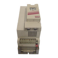
KEB COMBIVERT F5 Servo Applications Manual (334 pages)
Brand:
KEB
| Category:
Industrial Electrical
| Size: 3 MB
Table of Contents
Hardware
29
Table of Contents
29
Survey
31
Terminal Strip X2A
32
Connection of the Control
33
Digital Inputs
33
Voltage Input / External Power
35
Supply
35
Digital Outputs
35
Relay Outputs
35
Voltage Output
36
Analog Outputs
36
Fundamentals
37
ENTER-Parameter
40
Selection of a Parameter
40
Parameters
41
Resetting of Error Messages
41
Resetting of Peak Values
41
Signals
41
Operation
43
Drive-Mode
45
Operation
45
Password Levels
45
Password Structure
45
Changing of Password Level
46
Passwords
46
Operation
67
Adjustment Possibilities
69
Display and Keyboard
69
Rotation Setting
70
Start / Stop / Run
70
Further Settings
71
Leaving the Drive-Mode
71
Parameter
73
Parameter Groups
75
B-Housing
76
F5-BASIC Control
76
D-Housing
77
Parameter Listing F5-G
79
Functional Description
111
Analog Inputs
113
Interface Selection
114
Input Selection
115
Save Mode
115
Zero Point Hysteresis
116
Lower and Upper Limit
118
Analog Outputs
120
Analog Output / Functions
121
Output Signals
121
Analog Output / Display
122
Digital Settings
123
Period ANOUT3
123
Used Parameters
124
Functional Description
127
Edge-Triggering
131
Inversion of Inputs
131
Strobe-Dependent Inputs
132
Assignment of the Inputs
134
Inputs Status
134
Reset/Input Selection and Edge Evaluation
134
Output Filter
138
Output Signals
138
Switching Conditions
139
Conditions for Flags
142
Inverting of Switching
142
Linking the Switching
142
Selection of Switching
142
Inverting of Flags
143
Linking the Flags
143
Selection of Flags
143
Inversion of Outputs
144
Output Terminal Status
144
Example
145
Functional Description
203
Copying of Parameter Sets Via Bus
206
Keyboard
206
Parameters
206
Parameter Set Selection
207
Locking of Parameter Sets
210
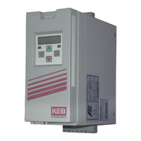
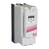
KEB COMBIVERT F5 Servo Installation Manual (56 pages)
digital servo controller Housing A
Brand:
KEB
| Category:
Controller
| Size: 3 MB
Table of Contents
Deutsch
5
Table of Contents
5
Anhang B
6
Geräteidentifikation
6
Technische Daten
7
Abmessungen und Anschlüsse
9
3 Einbau und Anschluss
11
Schaltschrankeinbau
11
EMV-Gerechte Verdrahtung
11
Anschluss des Leistungsteil
12
Verdrahtungshinweise
12
Klemmleiste X1A
12
Netzanschluss
13
Motoranschluss mit Klemmleiste X1B
13
Anschluss der Temperaturerfassung
14
Anschluss eines Bremswiderstandes mit Temperaturüberwachung Gemäß UL
15
Geberinterfaceanschluss
15
Resolveranschluss bei KEB Motoren über Buchse X3A
15
Inkrementalgebereingang / -Nachbildung X3B
16
Steuerkarte Servo
17
Steuerklemmleiste X2A
17
Anschluss der Steuerklemmleiste
18
4 Bedienung des Gerätes
19
Zubehör zur Bedienung
19
Ohne Operator mit HSP5-Servicekabel
19
Digitaloperator (Artikelnummer 00F5060-1000)
19
Interfaceoperator (Artikelnummer 00F5060-2000)
19
Fernbedienung
20
Weitere Operatoren
20
Tastaturbedienung
20
Parameternummern und /-Werte
20
Rücksetzen von Fehlermeldungen
21
Passworteingabe
21
Parameterbeschreibung für F5-Servo
22
English
31
1 Safety and Operating Instructions
32
2 Product Description
33
Intended Use
33
Unit Identification
33
Technical Data
34
Dimensions and Terminals
36
3 Installation and Connection
37
Control Cabinet Installation
37
EMC-Conform Installation
37
Connection of Power Circuit
38
Wiring Instructions
38
Terminal Strip X1A
38
Mains Connection
39
Motor Connection with Terminal Strip X1B
39
Connection of the Temperature Monitoring
40
Connection of a Braking Resistor with Temperature Monitoring in Accordance with UL
41
Encoder Interface Connection
41
Resolver Connection at KEB Motors with Connector X3A
41
Incremental Encoder Input / -Emulation X3B
42
Control Board Servo
43
Control Terminal Strip X2A
43
Connection of the Control Terminal Strip
44
4 Operation of the Unit
45
Operation Accessories
45
With HSP5 Cable and Without Operator
45
Digital Operator (Part Number 00F5060-1000)
45
Interface Operator (Part Number 00F5060-2000)
45
Remote Control
46
Other Operators
46
Keyboard Operation
46
Parameter Numbers and Values
46
Resetting Error Messages
47
Password Input
47
Advertisement
keb COMBIVERT F5 Servo Installation Manualline (28 pages)
Brand:
keb
| Category:
Inverter
| Size: 0 MB
Table of Contents
Table of Contents
3
1 Safety and Operating Instructions
4
2 Product Description
5
Intended Use
5
Unit Identification
5
Technical Data
6
Dimensions and Terminals
7
3 Installation and Connection
8
Control Cabinet Installation
8
EMC-Conform Installation
8
Connection of Power Circuit
9
Wiring Instructions
9
Terminal Strip X1.A
9
Mains Connection
10
Motor Connection Terminal Strip X1.B
10
Connection of the Temperature Monitoring
11
Connection of a Braking Resistor with Temperature Monitoring in Accordance with UL
12
Encoder Interface Connection
12
Resolver Connection at KEB Motors with Connector X3A
12
Incremental Encoder Input / -Emulation X3B
13
Control Board
14
Control Terminal Strip X2A
14
Connection of the Control Terminal Strip
15
4 Operation of the Unit
16
Operation Accessories
16
With HSP5 Cable and Without Operator
16
Digital Operator (Part Number 00.F5.060-1000)
16
Interface Operator (Part Number 00.F5.060-2000)
16
Remote Control (HSP5-Extension)
17
Other Operators
17
Keyboard Operation
17
Parameter Numbers and Values
17
Resetting Error Messages
18
Password Input
18
5 Parameter Description
19
6 Certifications
23
CE-Marking
23
Manufacturer´s Declaration
23
UL / CUL - Marking
23
7 Additional Manuals
24
Advertisement
Related Products
KEB combiverty
KEB COMBICONTROL C5
KEB COMBIVERTF6
KEB COMBIVERT F5 Series
KEB COMBIVERT F6 series
KEB COMBIVERT F5 GENERAL
KEB COMBIVERT G6 series
KEB COMBIVERT Z2
KEB COMBIVERT CONTROL G6 VARAN
KEB COMBIVERT SM
KEB Categories
DC Drives
Controller
Inverter
Control Unit
Industrial Equipment
More KEB Manuals
Login
Sign In
OR
Sign in with Facebook
Sign in with Google
Upload manual
Upload from disk
Upload from URL