KEB COMBIVERT G6 series Manuals
Manuals and User Guides for KEB COMBIVERT G6 series. We have 5 KEB COMBIVERT G6 series manuals available for free PDF download: Instructions For Use Manual, Installation Manual, Programming Manual
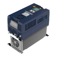
KEB COMBIVERT G6 series Instructions For Use Manual (54 pages)
INSTALLATION G6 HOUSING E
Table of Contents
Advertisement
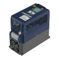
KEB COMBIVERT G6 series Instructions For Use Manual (52 pages)
INSTALLATION G6 HOUSING A
Table of Contents
Advertisement

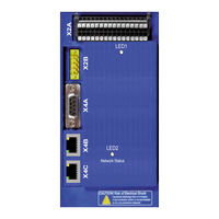
KEB COMBIVERT G6 series Programming Manual (32 pages)
Control circuit; EtherCAT
Brand: KEB
|
Category: Control Unit
|
Size: 0 MB
Table of Contents
Advertisement