Sign In
Upload
Manuals
Brands
KEB Manuals
DC Drives
COMBIVERT F6 series
KEB COMBIVERT F6 series Manuals
Manuals and User Guides for KEB COMBIVERT F6 series. We have
5
KEB COMBIVERT F6 series manuals available for free PDF download: Instructions For Use Manual, Instruction Manual
KEB COMBIVERT F6 series Instructions For Use Manual (92 pages)
Brand:
KEB
| Category:
Controller
| Size: 8 MB
Table of Contents
Signal Words and Symbols
3
More Symbols
3
Preface
4
Laws and Guidelines
4
Support
4
Copyright
4
Table of Contents
5
Warranty and Liability
5
Table of Contents
6
List of Figures
9
List of Tables
10
Glossary
11
Standards for Drive Converters / Control Cabinets
13
Product Standards that Apply Directly to the Drive Converter
13
Basic Standards to Which Drive Converter Standards Refer Directly
13
Standards that Are Used in the Environment of the Drive Converter
14
1 Basic Safety Instructions
15
Target Group
15
Transport, Storage and Proper Use
15
Installation
16
Electrical Connection
17
EMC-Compatible Installation
18
Voltage Test
18
Insulation Measurement
18
Start-Up and Operation
19
Maintenance
20
Repair
21
Disposal
21
2 Product Description
22
Specified Application
22
Residual Risks
22
Unintended Use
22
Product Features
23
Part Code
24
Table 1: Part Code
24
Nameplate
26
Figure 1: Nameplate
26
Configurable Options
27
Figure 2: Configurable Options
27
3 Technical Data
28
Operating Conditions
28
Climatic Environmental Conditions
28
Table 2: Climatic Environmental Conditions
28
Mechanical Ambient Conditions
29
Chemical / Mechanical Active Substances
29
Table 3: Mechanical Ambient Conditions
29
Table 4: Chemical / Mechanical Active Substances
29
Electrical Operating Conditions
30
Device Classification
30
Electromagnetic Compatibility
30
Table 5: Device Classification
30
Table 6: Electromagnetic Compatibility
30
Device Data of the 400 V Devices
31
Overview of the 400 V Devices
31
Voltage and Frequencies for 400V Devices
32
Table 7: Overview of the 400V Unit Data
32
Table 8: Input Voltages and Frequencies of the 400V Devices
32
Table 9: DC Link Voltage for 400V Devices
32
Example of the Calculation of the Possible Motor Voltage
33
Input and Output Currents/ Overload
33
Table 10: Output Voltages and Frequencies of the 400V Devices
33
Table 11: Example of the Calculation of the Possible Motor Voltage
33
Table 12: Input Currents of the 400 V Devices
33
Table 13: Output Currents of the 400 V Devices
33
Overload Characteristic (OL)
34
Figure 3: Switch-Off Time T Depending on the Overload I/IN at OC Level 180% (OL)
34
Frequency-Dependent Maximum Current (OL2)
35
Figure 4: Typical Overload Characteristics in the Lower Output Frequencies (OL2) Example
36
Table 14: Frequency-Dependent Maximum Current for Unit Size 21
37
Table 15: Frequency-Dependent Maximum Current for Device Size 22
38
Table 16: Frequency-Dependent Maximum Current for Device Size 23 (2 Khz)
38
Table 17: Frequency-Dependent Maximum Current for Device Size 23 (4 Khz)
39
Table 18: Frequency-Dependent Maximum Current for Device Size 23 (8 Khz)
39
Table 19: Frequency-Dependent Maximum Current for Device Size 24 (2 Khz)
40
Table 20: Frequency-Dependent Maximum Current for Device Size 24 (4 Khz)
40
Power Dissipation at Rated Operation
41
Protection of the Drive Controller
41
Table 21: Power Dissipation of the 400 V Devices
41
Table 22: Fusing of the 400 V / 480 V Devices
41
General Electrical Data
42
Switching Frequency and Temperature
42
Table 23: Switching Frequency and Temperature of the 400 V Devices
42
DC Link / Braking Transistor Function
43
Figure 5: Block Diagram of the Energy Flow
43
Sub-Mounted Braking Resistors
44
Table 24: DC Link / Braking Transistor Function of the 400 V Devices
44
Table 25: Sub-Mounted Braking Resistors
44
Fan
45
Table 26: Fan
45
Switching Behaviour of the Fans
46
Switching Points of the Fans
46
Figure 6: Switching Behaviour of the Fans Example Heat Sink Fan
46
Table 27: Switching Points of the Fans
46
Airflow Of The Drive Converter
47
Figure 7: Airflow of the Drive Converter
47
Dimensions and Weights
48
Built-In Version Air Cooler
48
Figure 8: Dimensions Built-In Version Air Cooler
48
Built-In Version Fluid Cooler (Water)
49
Figure 9: Dimensions Built-In Version Fluid Cooler (Water)
49
Push-Through Version Air Cooler IP20, IP54-Ready
50
Figure 10: Dimensions Push-Through Version Air Cooler IP20, IP54-Ready
50
Push-Through Version Fluid Cooler (Water) Ip20, Ip54-Ready
51
Figure 11: Dimensions Push-Through Version Fluid Cooler (Water) IP20, IP54-Ready
51
Push-Through Version Fluid Cooler (Oil) Ip20, Ip54-Ready
52
Figure 12: Dimensions Push-Through Version Fluid Cooler (Oil) IP20, IP54-Ready
52
Installation of IP54-Ready Devices
53
Figure 15: Installation of IP54-Ready Devices
53
Control Cabinet Installation
54
Mounting Instructions
54
Table 28: Mounting Instructions for Built-In Version
54
Table 29: Mounting Instructions for Push-Through Version
54
Mounting Distances
55
Figure 13: Mounting Distances
55
Figure 14: Control Cabinet Ventilation
55
4 Installation and Connection
56
Overview of the Combivert F6
56
Figure 16: F6 Housing 6 Top View
56
Figure 17: F6 Housing 6 Front View
57
Figure 18: F6 Housing 6 Rear View with Control Board COMPACT
58
Connection of the Power Unit
59
Connection of the Voltage Supply
59
Figure 19: Input Circuit
59
Terminal Block X1A for 400 V Units
60
Figure 20: Terminal Block X1A for 400 V Devices
60
Table 30: Crimp Connector Dimension X1A
60
Protective Earth and Function Earth
61
Protective Earth
61
Functional Earthing
61
Figure 21: Connection for Protective Earth
61
AC Mains Connection
62
AC Supply 3-Phase
62
Supply Cable
62
Figure 22: Connection of the Mains Supply 3-Phase
62
Note on Hard Power Systems
63
DC Connection
64
Terminal Block X1A DC Connection
64
Figure 23: Terminal Block X1A DC Connection
64
Table 31: Crimp Connector Dimension DC Connection
64
Connection of the Motor
65
Wiring of the Motor
65
Figure 24: Wiring of the Motor
65
Terminal Block X1A Motor Connection
66
Figure 25: Terminal Block X1A Motor Connection
66
Table 32: Crimp Connector Dimension Motor Connection
66
Selection of the Motor Line
67
Motor Cable Length and Conducted Interferences at AC Supply
67
Figure 26: Symmetrical Motor Line
67
Table 33: Max. Motor Cable Length
67
Motor Cable Length for Parallel Operation of Motors
68
Motor Cable Cross-Section
68
Interconnection of the Motor
68
Connection of the Temperature Monitoring and Brake Control (X1C)
69
Figure 27: Terminal Block X1C for Control Board APPLICATION and COMPACT
69
Figure 28: Terminal Block X1C for Control Board PRO
69
Figure 29: Connection of the Brake Control
70
Figure 30: Connection of a KTY Sensor
70
Connection and Use of a Braking Resistor
71
Installation Instructions for Side-Mounted Braking Resistors
71
Terminal Block X1A Connection Braking Resistor
72
Figure 31: Terminal Block X1A Connection Braking Resistor
72
Table 34: Crimp Connector Dimension Braking Resistor
72
Use of Non-Intrinsically Safe Braking Resistors
73
Accessories
74
Filters and Chokes
74
Seal for IP54-Ready Devices
74
Connections to the Coolant
74
Side-Mounted Braking Resistors
74
Table 35: Filters and Chokes
74
Table 36: Seal for IP54-Ready Devices
74
Table 37: Connections to the Coolant
74
5 Installation and Operation of Liquid-Cooled Devices
75
Water-Cooled Devices
75
Heat Sink and Operating Pressure
75
Materials in the Cooling Circuit
75
Requirements for the Coolant
76
Table 38: Electrochemical Series / Standard Potentials against Hydrogen
76
Table 39: Coolant Requirements for Water Coolers
76
Table 40: Special Requirements for Open and Half-Open Cooling Systems for Water Coolers
77
Connection of the Cooling System
78
Figure 32: Open Pipe Ends for the Connection of the Cooling System for Water Coolers
78
Coolant Temperature and Moisture Condensation
79
Condensation
79
Supply of Tempered Coolant
79
Table 41: Dew Point Table
79
Permissible Volume Flow With Water Cooling
80
Table 42: Permissible Volume Flow with Water Cooling
80
Coolant Heating with Water
81
Figure 33: Volume Flow Depending on the Total Power Dissipation Pd_Ges and Temperature Difference with Water-Glycol Mixture
81
Figure 33: Volume Flow Depending on the Total Power Dissipation Pd_Ges and Temperature
81
Typical Pressure Drop of the Heat Sink with Water
82
Figure 34: Typical Pressure Drop Depending on the Volume Flow
82
Oil-Cooled Devices
83
Heat Sink and Operating Pressure for Oil-Cooled Devices
83
Oil Requirements
83
Table 43: Oil Requirements
83
Table 44: Special Requirements for Open and Semi-Open Cooling Systems for Oil Coolers
83
Connection of the Oil Cooling System
84
Figure 35: Connection of the Oil Cooling System
84
Coolant Temperature and Condensation with Oil
85
Avoid Moisture Condensation
85
Table 45: Dew Point Table
85
Permissible Volume Flow With Oil
86
Table 46: Permissible Flow Rate for the Oil Cooler
86
6 Certification
87
Ce-Marking
87
UL Certification
88
Further Informations and Documentation
89
7 Revision History
90
Advertisement
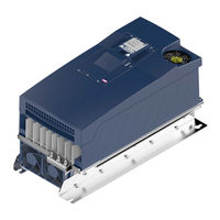
KEB COMBIVERT F6 series Instructions For Use Manual (84 pages)
INSTALLATION F6 HOUSING 2
Brand:
KEB
| Category:
Controller
| Size: 14 MB
Table of Contents
Preface
3
Signal Words and Symbols
3
More Symbols
3
Laws and Guidelines
4
Warranty and Liability
4
Support
4
Copyright
4
Table of Contents
5
List of Figures
8
List of Tables
9
Glossary
11
Standards for Drive Converters / Control Cabinets
13
Product Standards that Apply Directly to the Drive Converter
13
Basic Standards to Which Drive Converter Standards Refer Directly
13
Standards that Are Used in the Environment of the Drive Converter
14
1 Basic Safety Instructions
15
Target Group
15
Transport, Storage and Proper Use
15
Installation
16
Electrical Connection
17
EMC-Compatible Installation
18
Voltage Test
18
Insulation Measurement
18
Start-Up and Operation
19
Maintenance
20
Repair
21
Disposal
21
2 Product Description
22
Specified Application
22
Residual Risks
22
Unintended Use
22
Product Features
23
Part Code
24
Table 1: Part Code
25
3 Technical Data
26
Operating Conditions
26
Climatic Environmental Conditions
26
Table 2: Climatic Environmental Conditions
26
Mechanical Ambient Conditions
27
Chemical / Mechanical Active Substances
27
Table 3: Mechanical Ambient Conditions
27
Table 4: Chemical / Mechanical Active Substances
27
Electrical Operating Conditions
28
Device Classification
28
Electromagnetic Compatibility
28
Table 5: Device Classification
28
Table 6: Electromagnetic Compatibility
28
Device Data of the 230 V Devices
29
Overview of the 230 V Devices
29
Voltage and Frequencies for 230V Devices
30
Table 7: Overview of the 230V Device Data
30
Table 8: Input Voltages and Frequencies of the 230V Devices
30
Table 9: DC Link Voltage for 230V Devices
30
Table 10: Output Voltages and Frequencies of the 230V Devices
30
Example of the Calculation of the Possible Motor Voltage 230V
31
Input and Output Currents / Overload for 230 V Devices
31
Table 11: Example of the Calculation of the Possible Motor Voltage 230V
31
Table 12: Input Currents of the 230 V Devices
31
Table 13: Output Currents of the 230 V Devices
31
Overload Characteristic (OL) for 230 V Devices
32
Figure 1: Turn-Off Time T Depending on the Overload I/IN at OC Level 216
32
Figure 2: Turn-Off Time T Depending on the Overload I/IN at OC Level 180
33
Frequency-Dependent Maximum Current (OL2) for 230V Devices
34
Figure 3: Typical Overload Characteristics in the Lower Output Frequencies (OL2) Example
35
Table 14: Frequency-Dependent Maximum Current for Device Size 10
36
Table 15: Frequency-Dependent Maximum Current for Device Size 12
37
Table 16: Frequency-Dependent Maximum Current for Device Size 13
37
Power Dissipation at Rated Operation of the 230V Devices
38
Fuse Protection of the Drive Converters of the 230V Devices
38
Table 17: Frequency-Dependent Maximum Current for Device Size 14
38
Table 18: Power Dissipation of the 230 V Devices
38
Table 19: Fusing of the 230 V / 240 V Devices
38
Device Data of the 400 V Devices
39
Overview of the 400 V Devices
39
Voltage and Frequencies for 400V Devices
40
Table 20: Overview of the 400V Device Data
40
Table 21: Input Voltages and Frequencies of the 400V Devices
40
Table 22: DC Link Voltage for 400V Devices
40
Table 23: Output Voltages and Frequencies of the 400V Devices
40
Example of the Calculation of the Possible Motor Voltage
41
Input and Output Currents / Overload for 400 V Devices
41
Table 24: Example of the Calculation of the Possible Motor Voltage
41
Table 25: Input Currents of the 400 V Devices
41
Table 26: Output Currents of the 400 V Devices
41
Overload Characteristic (OL) for 400 V Devices
42
Figure 4: Turn-Off Time T Depending on the Overload I/IN at OC Level 216
42
Figure 5: Turn-Off Time T Depending on the Overload I/IN at OC Level 180
43
Frequency-Dependent Maximum Current (OL2) for 400V Devices
44
Figure 6: Typical Overload Characteristics in the Lower Output Frequencies (OL2) Example
45
Table 27: Frequency-Dependent Maximum Current for Device Size 12
46
Table 28: Frequency-Dependent Maximum Current for Device Size 13
46
Table 29: Frequency-Dependent Maximum Current for Device Size 14
47
Table 30: Frequency-Dependent Maximum Current for Device Size 15
47
Table 31: Frequency-Dependent Maximum Current for Device Size 16 (2 Khz)
48
Table 32: Frequency-Dependent Maximum Current for Device Size 16 (4 Khz)
48
Power Dissipation at Rated Operation of the 400 V Devices
49
Fuse Protection of the Drive Converters of the 400V Devices
49
Table 33: Power Dissipation of the 400 V Devices
49
Table 34: Fusing of the 400 V / 480 V Devices
49
General Electrical Data
50
Switching Frequency and Temperature of the 230 V Devices
50
Switching Frequency and Temperature of the 400 V Devices
50
Table 35: Switching Frequency and Temperature of the 230 V Devices
50
Table 36: Switching Frequency and Temperature of the 400 V Devices
50
DC Link / Braking Transistor Function (GTR7)
51
DC Link / Braking Transistor Function of the 230 V Devices
51
Figure 7: Block Diagram of the Energy Flow
51
Table 37: DC Link / Braking Transistor Function of the 230 V Devices
51
DC Link / Braking Transistor Function of the 400 V Devices
52
Fan
52
Table 38: DC Link / Braking Transistor Function of the 400 V Devices
52
Table 39: Fan
52
Switching Behaviour of the Fans
53
Switching Points of the Fans
53
Figure 8: Switching Behaviour of the Fan Example Heat Sink Fan
53
Table 40: Switching Points of the Fans
53
Dimensions and Weights
54
Built-In Version Air Cooler
54
Figure 9: Dimensions Built-In Version Air Cooler
54
Push-Through Version IP20
55
Figure 10: Dimensions Push-Through Version IP20
55
Push-Through Version IP54
56
Figure 11: Dimensions Push-Through Version IP54
56
Control Cabinet Installation
57
Mounting Instructions
57
Mounting Distances
57
Figure 12: Mounting Distances
57
Table 41: Mounting Instructions for Built-In Version
57
Table 42: Mounting Instructions for Push-Through Version
57
Figure 13: Control Cabinet Ventilation
58
4 Installation and Connection
59
Overview of the Combivert F6
59
Figure 14: F6 Housing 2 Top View
59
Figure 15: F6 Housing 2 Front View
60
Figure 16: F6 Housing 2 Rear View with Control Board APPLICATION
61
Connection of the Power Unit
62
Connection of the Voltage Supply
62
Figure 17: Input Circuit
62
Terminal Block X1A
63
Figure 18: Terminal Block X1A
63
Protective Earth and Function Earth
64
Protective Earth
64
Functional Earthing
64
Figure 19: Connection for Protective Earth
64
AC Mains Connection
65
AC Supply 3-Phase
65
Supply Line
65
Figure 20: Connection of the Mains Supply 3-Phase
65
Note on Hard Power Systems
66
DC Connection
67
Terminal Block X1A DC Connection
67
Figure 21: Terminal Block X1A DC Connection
67
Connection of the Motor
68
Wiring of the Motor
68
Terminal Block X1A Motor Connection
68
Figure 22: Wiring of the Motor
68
Figure 23: Terminal Block X1A Motor Connection
68
Selection of the Motor Line
69
Motor Cable Length and Conducted Interferences at AC Supply
69
Figure 24: Symmetrical Motor Line
69
Table 43: Max. Motor Cable Length
69
Motor Cable Length for Parallel Operation of Motors
70
Motor Cable Cross-Section
70
Interconnection of the Motor
70
Connection of the Temperature Monitoring and Brake Control (X1C)
71
Figure 25: Terminal Block X1C for Control Board APPLICATION and COMPACT
71
Figure 26: Terminal Block X1C for Control Board PRO
71
Figure 27: Connection of the Brake Control
72
Figure 28: Connection of a KTY Sensor
72
Connection and Use of a Braking Resistor
73
Installation Instructions for Side-Mounted Braking Resistors
73
Terminal Block X1A Connection Braking Resistor
74
Figure 29: Terminal Block X1A Connection Braking Resistor
74
Wiring of an Intrinsically Safe Braking Resistor
75
Using a Non-Intrinsically Safe Braking Resistor
75
Figure 30: Wiring of an Intrinsically Safe Braking Resistor
75
Accessories
76
Filters and Chokes
76
Mounting Kit Shield Connection Brakets
76
Mounting Kit Push-Through Frame for IP20 Devices
76
Table 44: Filters and Chokes for 230V Devices
76
Table 45: Filters and Chokes for 400V Devices
76
Table 46: Mounting Kit Shield Connection Brakets
76
Table 47: Mounting Kit for IP20 Devices
76
Side-Mounted Braking Resistors
77
5 Certification
78
Ce-Marking
78
UL Certification
79
Further Informations and Documentation
80
6 Revision History
81
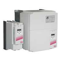
KEB COMBIVERT F6 series Instructions For Use Manual (76 pages)
INSTALLATION F6 HOUSING 2 PEAK POWER STANDARD OL-FUNCTION
Brand:
KEB
| Category:
DC Drives
| Size: 3 MB
Table of Contents
Preface
3
Signal Words and Symbols
3
More Symbols
3
Laws and Guidelines
4
Warranty and Liability
4
Support
4
Copyright
4
Table of Contents
5
List of Figures
8
List of Tables
9
Glossary
10
Standards for Drive Controllers
12
Product Standards that Apply Directly to the Drive Controller
12
Basic Standards to Which Drive Controller Standards Refer Directly
12
Standards that Are Used in the Environment of the Drive Controller
13
Basic Safety Instructions
14
Target Group
14
Transport, Storage and Proper Use
14
Installation
15
Electrical Connection
16
EMC-Compatible Installation
17
Voltage Test
17
Insulation Measurement
17
Start-Up and Operation
18
Maintenance
19
Repair
20
Disposal
20
Product Description
21
Specified Application
21
Residual Risks
21
Unintended Use
21
Product Features
22
Part Code
23
Table 1: Part Code
24
Nameplate
25
Figure 1: Nameplate
25
Configurable Options
26
Figure 2: Configurable Options
26
Technical Data
27
Operating Conditions
27
Climatic Environmental Conditions
27
Table 2: Climatic Environmental Conditions
27
Mechanical Environmental Conditions
28
Chemical / Mechanical Active Substances
28
Table 3: Mechanical Environmental Conditions
28
Table 4: Chemical / Mechanical Active Substances
28
Electrical Operating Conditions
29
Device Classification
29
Electromagnetic Compatibility
29
Table 5: Device Classification
29
Table 6: Electromagnetic Compatibility
29
Device Data of the Peak Power Devices
30
Overview of the Peak Power Devices
30
Voltage and Frequencies for 400V Devices
31
Table 7: Overview of the Peak Power Device Data
31
Table 8: Input Voltages and Frequencies of the 400V Devices
31
Table 9: DC Link Voltage for 400V Devices
31
Table 10: Output Voltages and Frequencies of the 400V Devices
31
Input and Output Currents / Overload for Peak Power Devices
32
Example of the Calculation of the Possible Motor Voltage
32
Table 12: Input Currents of the Peak Power Devices
32
Table 13: Output Currents of the Peak Power Devices
32
Table 11: Example of the Calculation of the Possible Motor Voltage
32
Overload Characteristic (OL) for Peak Power Devices
33
Figure 3: Switch-Off Time T Depending on the Overload I/IN at OC Level 230
34
Frequency-Dependent Maximum Current (OL2) for Peak Power Devices
35
Figure 4: Typical Overload Characteristics in the Lower Output Frequencies (OL2) Example
36
Power Dissipation at Rated Operation of the 400V Devices
37
Table 14: Frequency-Dependent Maximum Current for Device Size 16
37
Table 15: Power Dissipation of the Peak Power Devices
37
Fuse Protection of the Drive Controllers of the Peak Power Devices
38
Table 16: Fusing of the Peak Power Devices
38
General Electrical Data
39
Switching Frequency and Temperature
39
Switching Frequency and Temperature of the Peak Power Devices
39
Table 17: Switching Frequency and Temperature of the Peak Power Devices
39
DC Link / Braking Transistor Function
40
DC Link / Braking Transistor Function of the Peak Power Devices
40
Figure 5: Block Diagram of the Energy Flow
40
Table 18: DC Link / Braking Transistor Function of the Peak Power Devices
40
Fan
41
Table 19: Fan
41
Switching Behaviour of the Fans
42
Switching Points of the Fans
42
Figure 6: Switching Behaviour of the Fan Example Heat Sink Fan
42
Table 20: Switching Points of the Fans
42
Installation
43
Dimensions and Weights
43
Built-In Version Air Cooler
43
Figure 7: Dimensions Built-In Version Air Cooler
43
Push-Through Version Air Cooler IP20-Ready
44
Figure 8: Dimensions Push-Through Version Air Cooler IP20-Ready
44
Push-Through Version Air-Cooling IP54-Ready
45
Figure 9: Dimensions Push-Through Version Air Cooler IP54-Ready
45
Control Cabinet Installation
46
Mounting Instructions
46
Table 21: Mounting Instructions for Built-In Version
46
Table 22: Mounting Instructions for Push-Through Version
46
Mounting Distances
47
Figure 10: Mounting Distances
47
Installation of IP54-Ready Devices
48
Figure 11: Installation of IP54-Ready Devices
48
Control Cabinet Ventilation
49
Figure 12: Control Cabinet Ventilation
49
Airflow Of The Drive Converter
50
Figure 13: Airflow of the Drive Converter
50
Installation and Connection
51
Overview of the Combivert F6
51
Figure 14: F6 Housing 2 Top View
51
Figure 15: F6 Housing 2 Front View
52
Figure 16: F6 Housing 2 Rear View with Control Board APPLICATION
53
Connection of the Power Unit
54
Connection of the Voltage Supply
54
Figure 17: Input Circuit
54
Terminal Block X1A
55
Figure 18: Terminal Block X1A
55
Protective Earth and Functional Earth
56
Protective Earth
56
Functional Earthing
56
Figure 19: Connection for Protective Earth
56
AC Mains Connection
57
AC Supply 3-Phase
57
Mains Supply Line
57
Figure 20: Connection of the Mains Supply 3-Phase
57
Note on Hard Power Systems
58
DC Connection
59
Terminal Block X1A DC Connection
59
Figure 21: Terminal Block X1A DC Connection
59
Connection of the Motor
60
Wiring of the Motor
60
Figure 22: Wiring of the Motor
60
Terminal Block X1A Motor Connection
61
Figure 23: Terminal Block X1A Motor Connection
61
Selection of the Motor Line
62
Motor Cable Length and Conducted Interferences at AC Supply
62
Figure 24: Symmetrical Motor Line
62
Table 23: Max. Motor Cable Length
62
Motor Cable Length for Parallel Operation of Motors
63
Motor Cable Cross-Section
63
Interconnection of the Motor
63
Connection of the Temperature Monitoring and Brake Control (X1C)
64
Figure 25: Terminal Block X1C for Control Board APPLICATION and COMPACT
64
Figure 26: Terminal Block X1C for Control Board PRO
64
Figure 27: Connection of the Brake Control
65
Figure 28: Connection of a KTY Sensor
65
Connection and Use of a Braking Resistor
66
Terminal Block X1A Connection Braking Resistor
67
Figure 29: Terminal Block X1A Connection Braking Resistor
67
Use of Intrinsically Safe Braking Resistors
68
Use of Non-Intrinsically Safe Braking Resistors
68
Figure 30: Wiring of an Intrinsically Safe Braking Resistor
68
Accessories
69
Filters and Chokes
69
Mounting Kit Shield Connection Brakets
69
Mounting Kit Push-Through Frame for IP20-Ready Devices
69
Seal for IP54-Ready Devices
69
Table 24: Filters and Chokes for Peak Power Devices
69
Table 25: Mounting Kit Shield Connection Brakets
69
Table 26: Mounting Kit for IP20-Ready Devices
69
Table 27: Seal for IP54-Ready Devices
69
Side-Mounted Braking Resistors
70
Certification
71
CE-Marking
71
UL Certification
72
Further Informations and Documentation
73
Revision History
74
Advertisement
KEB COMBIVERT F6 series Instructions For Use Manual (34 pages)
Single axis frequency inverter
Brand:
KEB
| Category:
DC Drives
| Size: 2 MB
Table of Contents
Preface
3
Signal Words and Symbols
3
More Symbols
3
Laws and Guidelines
4
Warranty
4
Support
4
Copyright
4
Table of Contents
5
List of Figures
7
List of Tables
7
1 Basic Safety Instructions
8
Target Group
8
Validity of this Manual
8
Electrical Connection
9
Start-Up and Operation
9
2 Product Description
10
Specified Application
10
Residual Risks
10
Unintended Use
10
Ordering Information
11
Table 1: Ordering Information
11
3 Description of the Operator
12
Figure 1: Description of the Operator
12
Control Card Block Incl. Operator
13
Operating Conditions
13
Figure 2: Control Card Block Incl. Operator (Front Panel)
13
4 Interfaces
14
Operator Interface
14
Figure 3: Sub-D 9-Pole
14
Diagnostic Interfaces
15
Ethernet Interface
15
USB Interface
15
Figure 4: RJ45 Interface
15
Figure 5: USB Interface
15
5 Operation
16
Control Elements
16
Description of the Control Elements
16
Menu Bar
16
Function Keys and Function Bar
16
Figure 6: Control Elements
16
Initial Start-Up
17
Switching on
17
Figure 7: Main Menu
17
Table 2: Operator Files
17
Non-Changeable Parameters
18
Figure 8: Non-Changeable Parameters
18
Changeable Parameters
19
Changing with „Up" and „Down
19
Figure 9: Changeable Parameters
19
Figure 10: Set Selection
20
Selection of Subindicies
20
Figure 11: Numeric Input
21
Numeric Input
21
Table 3: Selection Abbreviations
21
Inverter Parameters
22
Figure 12: Operator Parameters
22
Operator Parameters
23
Figure 13: Operator Parameters
23
Figure 14: Operator Parameter Groups
23
Operator System Parameters (OS)
24
Fieldbus Parameters (Fb)
27
Debugging Parameters (Db)
28
Flash File System Parameters (Fi)
29
Parameter Backup
30
Up/Download
30
Figure 15: Parameter Backup
30
Figure 16: Up/Download
30
Work List
31
File Administration
31
Figure 17: Work List
31
Figure 18: File Administration
31
FTP Mode
32
Function Test of Keyboard and Display
32
Figure 19: FTP Mode
32
Figure 20: Function Test of Keyboard and Display
32
KEB COMBIVERT F6 series Instruction Manual (44 pages)
Brand:
KEB
| Category:
DC Drives
| Size: 2 MB
Table of Contents
Table of Contents
3
Preface
5
General
5
Safety Instructions
5
Validity and Liability
5
Copyright
6
Specified Application
6
Product Description
7
Part Code
8
Installation Instructions
9
Cooling Systems
9
Control Cabinet Installation
10
Safety and Operating Instructions
11
Technical Data
12
Operating Conditions
12
Technical Data of the 230V Class
13
Technical Data of the 400 V Class
14
DC Supply
15
Calculation of the DC Input Current
15
Internal Input Circuit
15
Dimensions and Weights
16
Terminal Strips of the Power Circuit
21
Permissible Cable Cross-Sections and Tightening Torques of the Terminals
21
Accessories
22
Filter and Chokes
22
Technical Data Filter
22
Technical Data Mains and Motor Choke
24
Connection Power Unit
25
Mains and Motor Connection
25
Selection of the Motor Cable
26
Connection of the Motor
26
Temperature Detection T1, T2
27
2.7.4.1 Use of the Temperature Input in KTY Mode
28
2.7.4.2 Use of the Temperature Input in PTC Mode
28
Connection of a Braking Resistor
29
2.7.5.1 Braking Resistor Without Temperature Monitoring
29
Braking Resistor with Over-Heat Protection and GTR7 Monitoring (Water-Cooled Inverters)
30
Braking Resistor with Over-Heat Protection and GTR7 Monitoring (Air-Cooled Inverters)
31
Annex a
32
Overload Characteristic
32
Overload Protection in the Lower Speed Range
32
Calculation of the Motor Voltage
33
Maintenance
33
Storage
33
Cooling Circuit
34
Annex B
35
Certification
35
CE Marking
35
UL Marking
35
Annex C
37
Installation of Water-Cooled Units
37
Heat Sink and Operating Pressure
37
Materials in the Cooling Circuit
37
Requirements on the Coolant
38
Connection to the Cooling System
39
Coolant Temperature and Moisture Condensation
39
C.1.6 Coolant Heating Depending On Power Loss And Flow Rate With Water
41
C.1.7 Typically Fall Of Pressure Depending On The Rate Of Flow
41
Annex D
42
Changing the Response Threshold of the Braking Transistor
42
Advertisement
Related Products
KEB COMBIVERT F5 Series
KEB COMBIVERT G6 series
KEB COMBIVERT Series
KEB COMBIVERTF6
KEB COMBIVERT F5 Servo
KEB COMBIVERT F5 GENERAL
KEB combiverty
KEB COMBIVERT H6 Series
KEB COMBIVERT Z2
KEB COMBIVERT CONTROL G6 VARAN
KEB Categories
DC Drives
Controller
Inverter
Control Unit
Industrial Equipment
More KEB Manuals
Login
Sign In
OR
Sign in with Facebook
Sign in with Google
Upload manual
Upload from disk
Upload from URL